JP2011106916A - Differential pressure measuring device - Google Patents
Differential pressure measuring device Download PDFInfo
- Publication number
- JP2011106916A JP2011106916A JP2009260941A JP2009260941A JP2011106916A JP 2011106916 A JP2011106916 A JP 2011106916A JP 2009260941 A JP2009260941 A JP 2009260941A JP 2009260941 A JP2009260941 A JP 2009260941A JP 2011106916 A JP2011106916 A JP 2011106916A
- Authority
- JP
- Japan
- Prior art keywords
- drain
- differential pressure
- pressure measuring
- measuring device
- relay
- Prior art date
- Legal status (The legal status is an assumption and is not a legal conclusion. Google has not performed a legal analysis and makes no representation as to the accuracy of the status listed.)
- Granted
Links
Images

Landscapes
- Measuring Fluid Pressure (AREA)
Abstract
【課題】簡易かつ低コストで加工でき、使用するユーザーが自由に長さを決定できるロングドレンプラグを有する差圧測定装置を実現する。
【解決手段】ドレインソケットとプラグとを有し差圧測定装置本体に取り付けられるドレインプラグユニットを具備する差圧測定装置において、柱状の中継ドレインソケット本体と、この中継ドレインソケット本体の一端側に設けられ前記ドレインソケットの雄ねじがねじ合わせ可能な雌ねじと、前記中継ドレインソケット本体の他端側に設けられ前記ドレインソケットの雄ねじと同じ雄ねじと、前記中継ドレインソケット本体の中心軸を貫通しドレインを抜くドレイン抜き孔とを具備し、前記ドレインプラグユニットと前記差圧測定装置本体との間に挿入配置される複数の中継ドレインソケットを具備したことを特徴とする差圧測定装置である。
【選択図】図1A differential pressure measuring apparatus having a long drain plug that can be processed easily and at low cost and whose length can be freely determined by a user to use is realized.
A differential pressure measuring device having a drain plug and a drain plug unit that is attached to a differential pressure measuring device main body and provided with a columnar relay drain socket main body and one end side of the relay drain socket main body. A male screw that can be screwed with the male screw of the drain socket, a male screw that is provided on the other end side of the relay drain socket body, the same male screw as the male screw of the drain socket, and passes through the central axis of the relay drain socket main body and pulls out the drain. A differential pressure measuring device comprising a plurality of relay drain sockets, each having a drain hole and inserted between the drain plug unit and the differential pressure measuring device main body.
[Selection] Figure 1
Description
本発明は、差圧測定装置に関するものである。
更に詳述すれば、差圧測定装置のドレン抜き用のドレンプラグユニットの改良に関するものである。
The present invention relates to a differential pressure measuring device.
More specifically, the present invention relates to an improvement of a drain plug unit for draining a differential pressure measuring device.
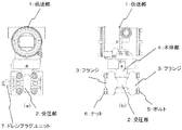
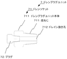
図8は従来より一般に使用されている従来例の要部構成説明図で、(a)は正面図、(b)は側面図、図9は図8の要部構成説明図、図10,図11は図8の動作説明図である。 8A and 8B are explanatory views of a main part configuration of a conventional example that is generally used conventionally. FIG. 8A is a front view, FIG. 8B is a side view, FIG. 9 is a main part configuration explanatory view of FIG. 11 is an operation explanatory diagram of FIG.
図において、2はプロセス流体が満たされ、プロセスからの圧力を受ける受圧部で、1は電源及びプロセスからの受けた圧力を信号に変換し出力を行う伝送部である。
受圧部2は、ボルト5とナット6により固定されるフランジ3と、圧力をセンサーにより伝送部1に伝える本体部4で構成される。
In the figure, reference numeral 2 denotes a pressure receiving unit which is filled with a process fluid and receives pressure from the process, and 1 is a transmission unit which converts the pressure received from the power source and the process into a signal and outputs the signal.
The pressure receiving unit 2 includes a flange 3 that is fixed by a bolt 5 and a
フランジ3には、メンテナンス時などに、受圧部に満たされているプロセス流体を抜くため(ドレン抜きを行うため)にシール剤やシールテープ、溶接などにより取り付けられたドレンプラグユニット7が具備されている。
ドレンプラグユニット7は、柱状のドレンプラグユニット本体711とフランジ3にねじ固定される雄ねじ712とドレイン抜き孔713を有するドレンソケット71と、ドレンソケット71のドレイン抜き孔713の一端側を塞ぎ、ドレン作業時にドレン抜きを行うプラグ72とで構成される。
The flange 3 is provided with a drain plug unit 7 attached by a sealant, a seal tape, welding or the like for draining the process fluid filled in the pressure receiving part during maintenance or the like (for draining). Yes.
The drain plug unit 7 closes one end side of the drain drain hole 713 of the drain socket 71 and a drain socket 71 having a drain drain hole 713 and a male screw 712 fixed to the flange 3 with a columnar drain plug unit main body 711. It is comprised with the plug 72 which drains at the time of work.
ドレイン抜き孔712は、通常、ドリル加工などで製作される。
図10に示す如く、プロセス流体が周囲温度等によって凝固が起こる場合、受圧部2はヒーターなどで保温される。この場合、図11に示す如く、ドレンプラグユニット7は保温材(ヒーター)8より外に出るように長くする必要がある。
ここで、「ドレンプラグを長く構成したもの」を「ロングドレンプラグ」と呼称する。
通常、一般のドレンプラグは20〜35mm程度、ロングドレンプラグは100〜150mm程度である。
The drain hole 712 is usually manufactured by drilling or the like.
As shown in FIG. 10, when the process fluid solidifies due to the ambient temperature or the like, the pressure receiving unit 2 is kept warm by a heater or the like. In this case, as shown in FIG. 11, the drain plug unit 7 needs to be longer than the heat insulating material (heater) 8.
Here, “a long drain plug” is referred to as a “long drain plug”.
Usually, a general drain plug is about 20 to 35 mm, and a long drain plug is about 100 to 150 mm.
このような装置においては、以下の問題点がある。
ロングドレンプラグ加工時、内部のドレイン抜き孔が長くなるので、ドレイン抜き孔の加工が困難である。
加工が困難であるため製作コストが高くなる。
製作したロングドレンプラグの長さであっても、保温材を巻いた際に短くなる場合が生ずる。
Such an apparatus has the following problems.
When a long drain plug is processed, the internal drain hole becomes long, so that it is difficult to process the drain hole.
Since the processing is difficult, the manufacturing cost increases.
Even the length of the manufactured long drain plug may be shortened when the heat insulating material is wound.
本発明の目的は、上記の課題を解決するもので、
簡易かつ低コストで加工でき、使用するユーザーが自由に長さを決定できるロングドレンプラグを有する差圧測定装置を提供することにある。
The object of the present invention is to solve the above problems.
An object of the present invention is to provide a differential pressure measuring device having a long drain plug that can be processed easily and at low cost, and whose length can be freely determined by a user.
このような課題を達成するために、本発明では、請求項1の差圧測定装置においては、
ドレインソケットとプラグとを有し差圧測定装置本体に取り付けられるドレインプラグユニットを具備する差圧測定装置において、柱状の中継ドレインソケット本体と、この中継ドレインソケット本体の一端側に設けられ前記ドレインソケットの雄ねじがねじ合わせ可能な雌ねじと、前記中継ドレインソケット本体の他端側に設けられ前記ドレインソケットの雄ねじと同じ雄ねじと、前記中継ドレインソケット本体の中心軸を貫通しドレインを抜くドレイン抜き孔とを具備し、前記ドレインプラグユニットと前記差圧測定装置本体との間に挿入配置される複数の中継ドレインソケットを具備したことを特徴とする。
In order to achieve such a problem, in the present invention, in the differential pressure measuring device of claim 1,
A differential pressure measuring device having a drain plug and a drain plug unit attached to the differential pressure measuring device main body, the columnar relay drain socket main body, and the drain socket provided on one end side of the relay drain socket main body A male screw that can be screwed together, a male screw that is provided on the other end side of the relay drain socket body and is the same as the male screw of the drain socket, and a drain hole that passes through the central axis of the relay drain socket body and extracts the drain. And a plurality of relay drain sockets inserted between the drain plug unit and the differential pressure measuring device main body.
本発明の請求項2の差圧測定装置においては、請求項1記載の差圧測定装置において、
前記継ドレインソケットはL字型あるいはU字型をなすことを特徴とする。
In the differential pressure measuring device according to claim 2 of the present invention, in the differential pressure measuring device according to claim 1,
The junction drain socket is L-shaped or U-shaped.
本発明の請求項3の差圧測定装置においては、請求項1又は請求項2記載の差圧測定装置において、
前記ドレイン抜き孔は放電加工により形成された孔であることを特徴とする。
In the differential pressure measuring device according to claim 3 of the present invention, in the differential pressure measuring device according to claim 1 or 2,
The drain hole is a hole formed by electric discharge machining.
本発明の請求項1によれば、次のような効果がある。
簡易かつ低コストで加工でき、使用するユーザーが自由に長さを決定できるロングドレンプラグを有する差圧測定装置が得られる。
According to claim 1 of the present invention, there are the following effects.
A differential pressure measuring device having a long drain plug that can be processed easily and at low cost and whose length can be freely determined by the user in use is obtained.
本発明の請求項2によれば、次のような効果がある。
ドレインの方向を容易に変える事ができる差圧測定装置が得られる。
According to claim 2 of the present invention, there are the following effects.
A differential pressure measuring device capable of easily changing the direction of the drain is obtained.
本発明の請求項3によれば、次のような効果がある。
ドレイン抜き孔は放電加工により形成された孔で構成されたので、孔を細くでき、中継ドレインソケットの強度を向上できる差圧測定装置が得られる。
According to claim 3 of the present invention, there are the following effects.
Since the drain hole is constituted by a hole formed by electric discharge machining, a differential pressure measuring device that can make the hole thin and improve the strength of the relay drain socket is obtained.
以下本発明を図面を用いて詳細に説明する。
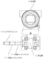
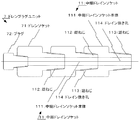
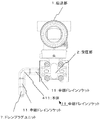
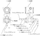
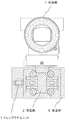
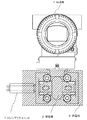
図1は本発明の一実施例の要部構成説明図、図2は図1の要部構成説明図、図3は図1の動作説明図である。
図において、図8と同一記号の構成は同一機能を表す。
以下、図8との相違部分のみ説明する。
Hereinafter, the present invention will be described in detail with reference to the drawings.
FIG. 1 is a diagram illustrating the configuration of the main part of one embodiment of the present invention, FIG. 2 is a diagram illustrating the configuration of the main part of FIG. 1, and FIG. 3 is a diagram illustrating the operation of FIG.
In the figure, the same symbols as those in FIG. 8 represent the same functions.
Only the difference from FIG. 8 will be described below.
図1,図2において、中継ドレインソケット11は、柱状の中継ドレインソケット本体111と、中継ドレインソケット本体111の一端側に設けられ、ドレインソケットの雄ねじ712がねじ合わせ可能な雌ねじ112と、中継ドレインソケット本体111の他端側に設けられ、ドレインソケットの雄ねじ712と同じ雄ねじ113と、中継ドレインソケット本体111の中心軸を貫通するドレイン抜き孔114とを有し、図1に示す如く、ドレインプラグユニット7と受圧部2との間に挿入配置され、複数個配置される。 1 and 2, a relay drain socket 11 is provided with a columnar relay drain socket main body 111, a female screw 112 provided on one end side of the relay drain socket main body 111, and a male screw 712 of the drain socket can be screwed together, and a relay drain socket. A drain plug 114 provided on the other end side of the socket body 111 and having the same male screw 113 as the male screw 712 of the drain socket and a drain hole 114 penetrating the central axis of the relay drain socket main body 111, as shown in FIG. Between the unit 7 and the pressure receiving part 2 are inserted and arranged, and a plurality of them are arranged.
この場合は、2個配置されている。
なお、中継ドレインソケット本体111は、ドレイン抜き孔114の加工が容易にできる最適な長さ、例えば、20〜35mmで製作されることが望ましい。
中継ドレインソケット本体111は金属材よりなり、この場合は、ステンレス鋼、難加工性材料のタンタル、モネル、チタン、高ニッケル鋼などの材料が使用される。
In this case, two are arranged.
The relay drain socket body 111 is preferably manufactured to have an optimal length that allows the drain hole 114 to be easily processed, for example, 20 to 35 mm.
The relay drain socket main body 111 is made of a metal material, and in this case, a material such as stainless steel, difficult-to-work material tantalum, monel, titanium, or high nickel steel is used.
以上の構成において、保温材8を用いた場合は、図3のごとく、ドレインプラグユニット7と複数の中継ドレインソケット11を連結させ、保温材8の外側にプラグ72が露出するように組み付ける。
中継ドレインソケット11を複数個連結することにより、ドレンプラグ全体の長さを自由に調整でき、保温材8の外部に露出するように調整できる。
In the above configuration, when the heat insulating material 8 is used, as shown in FIG. 3, the drain plug unit 7 and the plurality of relay drain sockets 11 are connected and assembled so that the plug 72 is exposed outside the heat insulating material 8.
By connecting a plurality of relay drain sockets 11, the entire length of the drain plug can be freely adjusted and adjusted so as to be exposed to the outside of the heat insulating material 8.
この結果、簡易、かつ低コストで加工でき、使用するユーザーが自由に長さを決定できるロングドレンプラグを有する差圧測定装置が得られる。 As a result, it is possible to obtain a differential pressure measuring device having a long drain plug that can be processed easily and at low cost and whose length can be freely determined by the user.
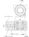
図4は、本発明の他の実施例の要部構成説明図である。
図4においては、ドレン抜きの際に、プラグ72に干渉する壁または防風・日よけなど温度変化を抑止するため用いられる防護箱21の中での使用された例を示す。
FIG. 4 is an explanatory view of the main part configuration of another embodiment of the present invention.
FIG. 4 shows an example of use in a protective box 21 used to suppress temperature changes such as a wall that interferes with the plug 72 or windproof / sunshade when draining.
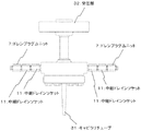
図5は、本発明の他の実施例の要部構成説明図である。
図5においては、キャピラリチューブ31で受圧部32と伝送器本体4を結ぶダイアフラムシール型差圧測定装置に使用された例を示す。
FIG. 5 is an explanatory view showing the configuration of the main part of another embodiment of the present invention.
In FIG. 5, the example used for the diaphragm seal type | mold differential pressure measuring apparatus which connects the pressure receiving part 32 and the transmitter main body 4 with the capillary tube 31 is shown.
図6は、本発明の他の実施例の要部構成説明図である。
図6においては、ドレンプラグ全体を、L型に形成したものである。
中継ドレインソケット11の本体411を所要の形状に曲げて、ドレンプラグ全体をL型に形成する。
したがって、本体411をU型などにすれば、ドレンプラグ全体をU型など様々な形状に製作できる。
FIG. 6 is an explanatory view of the main part configuration of another embodiment of the present invention.
In FIG. 6, the entire drain plug is formed in an L shape.
The main body 411 of the relay drain socket 11 is bent into a required shape, and the entire drain plug is formed in an L shape.
Therefore, if the main body 411 is U-shaped or the like, the entire drain plug can be manufactured in various shapes such as U-shaped.
図7は、本発明の他の実施例の要部構成説明図である。
図7においては、図1実施例においては、ドレンプラグをフランジに1箇所取り付けるようにしたが、側面に2箇所もしくは3箇所取り付けられるようにしたものである。
FIG. 7 is an explanatory view of the main part configuration of another embodiment of the present invention.
In FIG. 7, in the embodiment of FIG. 1, the drain plug is attached to the flange at one place, but it is attached to the side face at two places or three places.
なお、前述の実施例においては、中継ドレインソケット本体111の長さに付いて、中継ドレインソケット本体111は、ドレイン抜き孔114の加工が容易にできる最適な長さ、例えば、20〜35mmで製作されることが望ましいとしたが、これに限ることはなく、要するに、ドレイン抜き孔114の加工が容易にできる長さであれば良い。 In the above-described embodiment, the length of the relay drain socket main body 111 is attached, and the relay drain socket main body 111 is manufactured with an optimum length that can easily process the drain hole 114, for example, 20 to 35 mm. However, the present invention is not limited to this. In short, any length may be used as long as the drain hole 114 can be easily processed.
また、ドレイン抜き孔114の加工はドリル加工としたが、放電加工でも良い。放電加工によれば、細い孔を加工できるので、中継ドレインソケット本体111の強度を向上することができる。 Further, although the drain hole 114 is processed by drilling, electric discharge machining may be used. According to the electric discharge machining, since the narrow hole can be machined, the strength of the relay drain socket body 111 can be improved.
なお、以上の説明は、本発明の説明および例示を目的として特定の好適な実施例を示したに過ぎない。
したがって本発明は、上記実施例に限定されることなく、その本質から逸脱しない範囲で更に多くの変更、変形をも含むものである。
The above description merely shows a specific preferred embodiment for the purpose of explanation and illustration of the present invention.
Therefore, the present invention is not limited to the above-described embodiments, and includes many changes and modifications without departing from the essence thereof.
1 伝送部
2 受圧部
3 フランジ
4 本体部
5 ボルト
6 ナット
7 ドレンプラグユニット
8 保温材
71 ドレンソケット
711 ドレンプラグユニット本体
712 雄ねじ
713 ドレイン抜き孔
72 プラグ
11 中継ドレインソケット
111 中継ドレインソケット本体
112 雌ねじ
113 雄ねじ
114 ドレイン抜き孔
21 防護箱
31 キャピラリチューブ
32 受圧部
411 本体
DESCRIPTION OF SYMBOLS 1 Transmission part 2 Pressure receiving part 3 Flange 4 Main body part 5
Claims (3)
柱状の中継ドレインソケット本体と、
この中継ドレインソケット本体の一端側に設けられ前記ドレインソケットの雄ねじがねじ合わせ可能な雌ねじと、
前記中継ドレインソケット本体の他端側に設けられ前記ドレインソケットの雄ねじと同じ雄ねじと、
前記中継ドレインソケット本体の中心軸を貫通しドレインを抜くドレイン抜き孔と
を具備し、
前記ドレインプラグユニットと前記差圧測定装置本体との間に挿入配置される複数の中継ドレインソケット
を具備したことを特徴とする差圧測定装置。 In the differential pressure measuring device comprising a drain plug unit having a drain socket and a plug and attached to the differential pressure measuring device main body,
A columnar relay drain socket body;
A female screw provided on one end side of the relay drain socket body and capable of being screwed with the male screw of the drain socket;
The same external thread as the external thread of the drain socket provided on the other end side of the relay drain socket body,
A drain hole that penetrates the central axis of the relay drain socket body and extracts the drain;
A differential pressure measuring device comprising a plurality of relay drain sockets inserted and arranged between the drain plug unit and the differential pressure measuring device main body.
を特徴とする請求項1記載の差圧測定装置。 The differential pressure measuring device according to claim 1, wherein the joint drain socket is L-shaped or U-shaped.
を特徴とする請求項1又は請求項2記載の差圧測定装置。 The differential pressure measuring device according to claim 1, wherein the drain hole is a hole formed by electric discharge machining.
Priority Applications (1)
| Application Number | Priority Date | Filing Date | Title |
|---|---|---|---|
| JP2009260941A JP5601492B2 (en) | 2009-11-16 | 2009-11-16 | Differential pressure measuring device |
Applications Claiming Priority (1)
| Application Number | Priority Date | Filing Date | Title |
|---|---|---|---|
| JP2009260941A JP5601492B2 (en) | 2009-11-16 | 2009-11-16 | Differential pressure measuring device |
Publications (2)
| Publication Number | Publication Date |
|---|---|
| JP2011106916A true JP2011106916A (en) | 2011-06-02 |
| JP5601492B2 JP5601492B2 (en) | 2014-10-08 |
Family
ID=44230565
Family Applications (1)
| Application Number | Title | Priority Date | Filing Date |
|---|---|---|---|
| JP2009260941A Active JP5601492B2 (en) | 2009-11-16 | 2009-11-16 | Differential pressure measuring device |
Country Status (1)
| Country | Link |
|---|---|
| JP (1) | JP5601492B2 (en) |
Families Citing this family (1)
| Publication number | Priority date | Publication date | Assignee | Title |
|---|---|---|---|---|
| KR101720968B1 (en) * | 2015-06-16 | 2017-03-29 | 주식회사 엔박 | a muiti directional flange for differential capacitive pressure sensor |
Citations (9)
| Publication number | Priority date | Publication date | Assignee | Title |
|---|---|---|---|---|
| JPS6331350U (en) * | 1986-08-14 | 1988-02-29 | ||
| JPH062190U (en) * | 1992-06-16 | 1994-01-14 | 横河電機株式会社 | Differential pressure measuring device |
| JPH085493A (en) * | 1994-06-23 | 1996-01-12 | Yazaki Corp | Gas meter pressure detecting instrument and its pressure detecting method |
| JP3023165U (en) * | 1995-09-26 | 1996-04-12 | 東尾メック株式会社 | Test plug |
| JP2000505854A (en) * | 1996-08-26 | 2000-05-16 | エンヴァイロリューション インコーポレイテッド | Adapter system for engine flushing equipment |
| JP2000283399A (en) * | 1999-03-31 | 2000-10-13 | Tokyo Gas Co Ltd | Piping mechanism of pressure guiding tube for transmitter |
| JP2003227770A (en) * | 2002-02-05 | 2003-08-15 | Yokogawa Electric Corp | Differential pressure transmitter and method for estimating temperature of differential pressure transmitter |
| JP2005221350A (en) * | 2004-02-05 | 2005-08-18 | Yokogawa Electric Corp | Process connector for differential pressure measuring device |
| JP2006029639A (en) * | 2004-07-13 | 2006-02-02 | Mitsubishi Kagaku Sanshi Corp | Air conditioning system |
-
2009
- 2009-11-16 JP JP2009260941A patent/JP5601492B2/en active Active
Patent Citations (9)
| Publication number | Priority date | Publication date | Assignee | Title |
|---|---|---|---|---|
| JPS6331350U (en) * | 1986-08-14 | 1988-02-29 | ||
| JPH062190U (en) * | 1992-06-16 | 1994-01-14 | 横河電機株式会社 | Differential pressure measuring device |
| JPH085493A (en) * | 1994-06-23 | 1996-01-12 | Yazaki Corp | Gas meter pressure detecting instrument and its pressure detecting method |
| JP3023165U (en) * | 1995-09-26 | 1996-04-12 | 東尾メック株式会社 | Test plug |
| JP2000505854A (en) * | 1996-08-26 | 2000-05-16 | エンヴァイロリューション インコーポレイテッド | Adapter system for engine flushing equipment |
| JP2000283399A (en) * | 1999-03-31 | 2000-10-13 | Tokyo Gas Co Ltd | Piping mechanism of pressure guiding tube for transmitter |
| JP2003227770A (en) * | 2002-02-05 | 2003-08-15 | Yokogawa Electric Corp | Differential pressure transmitter and method for estimating temperature of differential pressure transmitter |
| JP2005221350A (en) * | 2004-02-05 | 2005-08-18 | Yokogawa Electric Corp | Process connector for differential pressure measuring device |
| JP2006029639A (en) * | 2004-07-13 | 2006-02-02 | Mitsubishi Kagaku Sanshi Corp | Air conditioning system |
Non-Patent Citations (1)
| Title |
|---|
| JPN6013002780; 「JISハンドブック 配管」 第1版第1刷, 19940420, p.623-642, 財団法人日本規格協会 * |
Also Published As
| Publication number | Publication date |
|---|---|
| JP5601492B2 (en) | 2014-10-08 |
Similar Documents
| Publication | Publication Date | Title |
|---|---|---|
| JP5973474B2 (en) | Flame arrester for process transmitter | |
| JP5685701B2 (en) | Temperature sensor device and assembly method | |
| US9766101B2 (en) | Apparatus for determining or monitoring a process variable of a medium in a pipeline | |
| JP5601492B2 (en) | Differential pressure measuring device | |
| JP4709569B2 (en) | Thermocouple mounting structure for continuous casting mold | |
| JP3189587U (en) | Vacuum insulation cup cover | |
| CN106595891A (en) | Transient response high temperature sensor applied to complex environment | |
| JP2006220430A5 (en) | ||
| CN210243057U (en) | Sanitary quick-load oil flush pressure transmitter | |
| CN102103022A (en) | Device for measuring temperature of titanium tetrachloride pulp pipeline | |
| CN210180552U (en) | Thermocouple with conveniently replaced accessory | |
| CN117307841A (en) | A sensing structure integrated flange with parameter monitoring function | |
| CN211085493U (en) | Thermocouple vacuum leading-in device capable of being installed quickly | |
| CN205141355U (en) | Cutting ferrule formula seal cooling water pipe connector's laser instrument | |
| EP2202497A1 (en) | Flow meter housing manufactured by cold-forming | |
| CN202994322U (en) | Armored platinum resistor with segmented tube joint | |
| CN202483563U (en) | Sensor and oil pipe structure | |
| JP2007162742A (en) | Biting type pipe joint and refrigeration cycle apparatus using the same | |
| CN212205086U (en) | Electric heating tube plate structure | |
| CN213288830U (en) | Shell structure of temperature sensor | |
| CN204699506U (en) | The end cover structure that a kind of buckle-type connects and filter core | |
| CN210950360U (en) | Heat-preservation elbow | |
| CN216284087U (en) | Gauge head shell of nuclear-grade pressure transmitter | |
| CN204164509U (en) | Thermocouple Seals | |
| CN210268683U (en) | Composite sensor structure with long probe |
Legal Events
| Date | Code | Title | Description |
|---|---|---|---|
| A621 | Written request for application examination |
Free format text: JAPANESE INTERMEDIATE CODE: A621 Effective date: 20120810 |
|
| A977 | Report on retrieval |
Free format text: JAPANESE INTERMEDIATE CODE: A971007 Effective date: 20130123 |
|
| A131 | Notification of reasons for refusal |
Free format text: JAPANESE INTERMEDIATE CODE: A131 Effective date: 20130128 |
|
| A521 | Written amendment |
Free format text: JAPANESE INTERMEDIATE CODE: A523 Effective date: 20130222 |
|
| A131 | Notification of reasons for refusal |
Free format text: JAPANESE INTERMEDIATE CODE: A131 Effective date: 20131126 |
|
| A521 | Written amendment |
Free format text: JAPANESE INTERMEDIATE CODE: A523 Effective date: 20131224 |
|
| TRDD | Decision of grant or rejection written | ||
| A01 | Written decision to grant a patent or to grant a registration (utility model) |
Free format text: JAPANESE INTERMEDIATE CODE: A01 Effective date: 20140724 |
|
| A61 | First payment of annual fees (during grant procedure) |
Free format text: JAPANESE INTERMEDIATE CODE: A61 Effective date: 20140806 |
|
| R150 | Certificate of patent or registration of utility model |
Ref document number: 5601492 Country of ref document: JP Free format text: JAPANESE INTERMEDIATE CODE: R150 |