JP2011106902A - Vacuum detector - Google Patents
Vacuum detector Download PDFInfo
- Publication number
- JP2011106902A JP2011106902A JP2009260703A JP2009260703A JP2011106902A JP 2011106902 A JP2011106902 A JP 2011106902A JP 2009260703 A JP2009260703 A JP 2009260703A JP 2009260703 A JP2009260703 A JP 2009260703A JP 2011106902 A JP2011106902 A JP 2011106902A
- Authority
- JP
- Japan
- Prior art keywords
- hole
- vacuum
- cap
- mounting portion
- state
- Prior art date
- Legal status (The legal status is an assumption and is not a legal conclusion. Google has not performed a legal analysis and makes no representation as to the accuracy of the status listed.)
- Granted
Links
- 238000006073 displacement reaction Methods 0.000 claims description 7
- 238000001514 detection method Methods 0.000 abstract description 5
- XLYOFNOQVPJJNP-UHFFFAOYSA-N water Substances O XLYOFNOQVPJJNP-UHFFFAOYSA-N 0.000 description 15
- 230000002093 peripheral effect Effects 0.000 description 12
- 238000012856 packing Methods 0.000 description 7
- 230000000694 effects Effects 0.000 description 4
- 230000015556 catabolic process Effects 0.000 description 2
- 238000006731 degradation reaction Methods 0.000 description 2
- 230000008014 freezing Effects 0.000 description 2
- 238000007710 freezing Methods 0.000 description 2
- 206010073261 Ovarian theca cell tumour Diseases 0.000 description 1
- 238000007796 conventional method Methods 0.000 description 1
- 239000012530 fluid Substances 0.000 description 1
- 238000009413 insulation Methods 0.000 description 1
- 239000011347 resin Substances 0.000 description 1
- 229920005989 resin Polymers 0.000 description 1
- 239000004071 soot Substances 0.000 description 1
- 208000001644 thecoma Diseases 0.000 description 1
Images
Landscapes
- Measuring Fluid Pressure (AREA)
Abstract
Description
本発明は、真空容器内の真空が保たれているか否かを検出する真空検出器に関するものである。 The present invention relates to a vacuum detector that detects whether or not a vacuum in a vacuum vessel is maintained.
気体の圧力を測定する計器として、例えば、特許文献1に示されるブルドン菅圧力計がある。このブルドン菅圧力計は、C型の扁平なブルドン菅の一端を菅支持体に設けられた圧力導入路に接続し、このブルドン菅の自由端に変位拡大機構を設け、また菅支持体の上端にねじ止めされたプレートに支持されている指針軸にピニオンを固定して、このピニオンに前記変位拡大機構を係合させ、更に圧力導入路の圧力源側には絞りユニットを設けた構成を備え、圧力流体が絞りユニットを介して圧力導入路からブルドン菅に進入することで圧力を測定するものとなっている。 As an instrument for measuring the pressure of gas, for example, there is a Bourdon soot pressure gauge disclosed in Patent Document 1. This Bourdon saddle pressure gauge has one end of a C-shaped flat Bourdon saddle connected to a pressure introduction path provided in the saddle support, a displacement expansion mechanism provided at the free end of the bourdon saddle, and the upper end of the saddle support A pinion is fixed to a pointer shaft supported by a plate screwed to the plate, the displacement enlarging mechanism is engaged with the pinion, and a throttle unit is provided on the pressure source side of the pressure introduction path. The pressure is measured by the pressure fluid entering the Bourdon pass through the pressure introduction path via the throttle unit.
しかしながら、上述した従来の技術においては、複雑な構造の変位拡大機構や絞りユニットを必要とし、かつ部品点数も多いため、高価であるという問題がある。 However, the above-described conventional technique has a problem that it is expensive because it requires a displacement magnifying mechanism and a diaphragm unit having a complicated structure and has a large number of parts.
また、絞りユニットに設けられる狭窄部材やブルドン菅等の部品が常に圧力を受けるために、これらの部品が劣化し易いという問題もある。 In addition, since components such as a constricting member and a Bourdon bag provided in the diaphragm unit are constantly subjected to pressure, there is a problem that these components are likely to deteriorate.
本発明は、このような問題を解決することができる真空検出器を実現することを課題とする。 This invention makes it a subject to implement | achieve the vacuum detector which can solve such a problem.
そのため、本発明の真空検出器は、中心部軸方向に透孔を有し、一端にキャップ装着部を形成すると共に他端に取付け部を形成した検出器本体と、前記透孔の位置に配置され、透孔を閉止状態と開放状態に切替える切替え弁と、この切替え弁を前記検出器本体の外側から操作するレバーと、軸方向の端面を成す壁面部に貫通孔を有し、かつ前記キャップ装着部に着脱可能に装着されたキャップと、片面側に軸部を有し、該軸部を前記キャップの貫通孔に挿入して前記キャップ内に移動可能に収納されたコマを備え、前記取付け部により真空容器に取付けた状態で、前記レバーの操作により前記切替え弁を操作することにより前記透孔を閉止状態から開放状態に切替えて前記真空容器内と前記キャップ装着部を連通させたとき、前記真空容器内が所期の真空状態であると、前記コマが前記キャップ装着部の端面に吸着されて前記軸部の変位状態が保たれるようにしたことを特徴とする。 Therefore, the vacuum detector of the present invention has a detector body having a through hole in the axial direction of the central portion, a cap mounting portion formed at one end and an attachment portion at the other end, and the position of the through hole. A switching valve that switches the through hole between a closed state and an open state, a lever that operates the switching valve from the outside of the detector body, a through hole in a wall surface portion that forms an axial end surface, and the cap A cap that is detachably mounted on the mounting portion, and a frame that has a shaft portion on one side, is inserted into the through hole of the cap, and is movably housed in the cap, When the through-hole is switched from a closed state to an open state by operating the switching valve by operating the lever in a state attached to the vacuum container by the part, the inside of the vacuum container and the cap mounting part communicate with each other. Inside the vacuum vessel If it is desired vacuum state, wherein said frame has as the displacement state of the shaft portion is attracted to the end face of the cap attachment portion is maintained.
このようにした本発明は、簡単な構成で部品点数が少なく、確実に真空状態の検出を行うことが可能な安価な真空検出器を提供できるという効果が得られる。 The present invention thus configured has an effect that it is possible to provide an inexpensive vacuum detector capable of reliably detecting a vacuum state with a simple configuration and a small number of parts.
また、真空状態の検出時以外は部品が動作せず、真空による負圧がかかることがないので、部品の劣化を最小限に抑えることも可能になるという効果も得られる。 In addition, since the component does not operate except when a vacuum state is detected and no negative pressure is applied due to the vacuum, it is possible to obtain an effect that the degradation of the component can be minimized.
以下、図面を参照して本発明による真空検出器の実施例を説明する。 Embodiments of a vacuum detector according to the present invention will be described below with reference to the drawings.
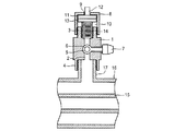
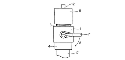
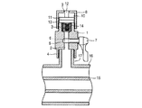
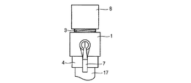
図1は実施例を示す通常時の側断面図、図2は実施例を示す通常時の正面図、図3は実施例を示す真空検出時の側断面図、図4は実施例を示す真空検出時の正面図である。 1 is a side sectional view in a normal state showing an embodiment, FIG. 2 is a front view in a normal state showing the embodiment, FIG. 3 is a side sectional view in a vacuum detection showing the embodiment, and FIG. 4 is a vacuum showing the embodiment. It is a front view at the time of detection.
図において1は検出器本体で、中心部軸方向に透孔2を有している。この検出器本体1の一端には透孔2の径より大きい内径を有する筒状のキャップ装着部3が一体に形成されていて、このキャップ装着部3の外周面にはネジが切られている。また、検出器本体1の他端にも透孔2の径より大きい内径を有する筒状の取付け部4が一体に形成されていて、この取付け部4の内周にはネジが切られており、そしてこの取付け部4とキャップ装着部3は透孔2により連通したものとなっている。
In the figure, reference numeral 1 denotes a detector main body, which has a through hole 2 in the central axis direction. A cylindrical
5は透孔2と直交するように検出器本体1に設けられた取付け穴内に回転可能に装着されたボール弁(切替え弁)で、透孔2と交叉する位置に該透孔2と同程度の径を有する開放孔6が設けられている。このボール弁5の軸部は検出器本体1から突出し、その突出部分にレバー7が設けられており、検出器本体1の外側でこのレバー7を操作してボール弁5を90度回転させることにより透孔2を閉止状態と開放孔6による開放状態に切替えられるようになっている。
8はキャップで、筒状部と、この筒状部の軸方向の一端面を成す壁面部からなり、この壁面部の中央には貫通孔9が設けられている。このキャップ8の内部の壁面部側はコマ収納部10となっていて、このコマ収納部を除く内周面にはネジが切られており、この内周面のネジ部をキャップ装着部3の外周面に設けたネジ部と螺合締結することによりキャップ8はキャップ装着部3に着脱可能に装着されている。
11はキャップ8のコマ収納部10より若干小さな径の円板状に形成したコマで、片面中央部に軸部12を有し、他面にゴムあるいは樹脂等によるパッキン13が設けられている。このコマ11はキャップ8のコマ収納部10内に軸方向へ移動できるように収納されており、かつ軸部12が貫通孔9に挿入されている。14はコイルスプリングで、検出器本体1の透孔2とキャップ装着部3の内径との径の差により形成される段差面とコマ11に設けたパッキン13との間に配されており、このコイルスプリング14によりパッキン13を介してコマ11がキャップ8の壁面部側に付勢され、コマ11の軸部12を貫通孔9から外部に突出させている。
以上の部品により本実施例の真空検出器が構成されるが、この構成においてコマ11及びコイルスプリング14を組み付けは、コマ11をキャップ8のコマ収納部10内に収納して軸部12を貫通孔9に挿通し、またコイルスプリング14の一端側をキャップ装着部3内に入れて段差面に載せて、キャップ5の内周面のネジ部をキャップ装着部3の外周面に設けたネジ部と螺合させることにより行う。
The vacuum detector of the present embodiment is configured by the above components. In this configuration, the
15は例えば寒冷地に敷設される水道管、16は水道管15より径の大きい鞘管で、水道管15はこの鞘管16内に配置されている。17は検出器取付け部で、上記真空検出器の取付け部4の内径と同等の外径を有し、その外周面にはネジが切られている。この検出器取付け部17は鞘管16内に通じるように鞘管16の外周面側に設けられていて、真空検出器の取付け部4の内周面に切られたネジ部を検出器取付け部17の外周面に切られたネジ部に螺合締結することで真空検出器は鞘管16に取付けられる。
For example, 15 is a water pipe laid in a cold region, 16 is a sheath pipe having a diameter larger than that of the
上述した構成の作用について説明する。 The operation of the above configuration will be described.
水道管15と鞘管16との間の空間は密封されており、水道管15と鞘管16との間の空間は真空状態(負圧)に保つものとなっている。これにより水道管15と鞘管16はいわゆる魔法瓶の構造(真空容器)となり、保温性が確保されて水道管15の凍結を防止できるものとなっている。また、真空検出器は、通常、図1、図2に示したようにボール弁5が透孔2を閉止した状態にあって、コマ11は負圧の影響を受けないため、コイルスプリング14の付勢力によりコマ11はキャップ8の壁面部側に付勢され、これにより軸部12が貫通孔9から外部に突出している。
The space between the
そこで、水道管15と鞘管16との間の空間が所期の真空状態(例えば、圧力レンジ最小メモリ−0.1MPa以下)に保たれているか否かを検出する場合、図3、図4に示すように、まず操作者が軸部12の先端を指で押込んでコマ11を移動させ、このコマ11に設けられているパッキン13をキャップ装着部3の端面に押し当てる。この状態のままレバー7を図2に示す矢印Aの方向に回してボール弁5を90度回転させると、ボール弁5に設けられている開放孔6が透孔2と同じ向きになるため、透孔2が開放状態となり、これにより水道管15と鞘管16との間の空間とキャップ装着部3の内部が連通する。
Therefore, when detecting whether or not the space between the
そのため、水道管15と鞘管16との間の空間化初期の真空状態であれば、負圧による吸引力によりパッキン13が吸引されてキャップ装着部3の端面に密着するため、コマ11の軸部12から指を離してもコマ11は動かず、変位状態のまま軸部12は外部に突出しないので、水道管15と鞘管16との間の空間は所期の真空状態に保たれていることが検出されることになる。
For this reason, in the initial vacuum state between the
もし、水道管15と鞘管16との間の空間が所期の真空状態より高い負圧の状態あるいは大気圧になっている場合は、コマ11の軸部12から指を離すと、コイルスプリング14の付勢力によりパッキン13と共にコマ11がキャップ8の壁面部側に移動し、コマ11の軸部12が貫通孔9から外部に突出することになる。
If the space between the
従って、操作者はコマ11の軸部12の変位状態、つまり軸部12が貫通孔9から外部に突出したか否かにより水道管15と鞘管16との間の空間が初期の真空状態に保たれているか否かを確認することが可能となる。
Therefore, the operator changes the space between the
以上説明した実施例の真空検出器は、中心部軸方向に透孔2を有する検出器本体1の一端にキャップ装着部3を形成すると共に他端に取付け部4を形成し、透孔2を閉止状態と開放状態に切替えるボール弁5と、このボール弁5を検出器本体1の外側から操作するレバー7を設け、また、軸方向の端面を成す壁面部に貫通孔9を有するキャップ8をキャップ装着部3に着脱可能に装着すると共に、このキャップ8内にコマ11を移動可能に収納して、このコマ11の片面側に設けた軸部12をキャップ8の貫通孔9に挿入し、更に軸部12が貫通穴9から外部に突出するようにコマ11を付勢するコイルスプリング14をキャップ装着部3内に配した構成として、取付け部4により内部を真空状態にする鞘管16に取付けた状態で、レバー7の操作によりボール弁5を回転させることにより透孔2を閉止状態から開放状態に切替えて鞘管16内とキャップ装着部3を連通させたとき、鞘管16内が所期の真空状態であると、コマ11がキャップ装着部3の端面に吸着されて軸部12の変位状態が保たれ、これにより真空状態が保たれていることが検出できるようにしている。そのため、簡単な構成で部品点数が少なく、確実に真空状態の検出を行うことが可能な安価な真空検出器を提供できるという効果が得られる。
In the vacuum detector of the embodiment described above, the
また、真空状態の検出時以外は部品が動作せず、真空による負圧がかかることがないので、部品の劣化を最小限に抑えることも可能になるという効果も得られる。 In addition, since the component does not operate except when a vacuum state is detected and no negative pressure is applied due to the vacuum, it is possible to obtain an effect that the degradation of the component can be minimized.
尚、上述した実施例では、図に示したようにキャップ8が上側になるように真空検出器を鞘管16に取付けているが、キャップ8が下側になるように真空検出器を鞘管16に取付けた場合は、自重によりコマ11が下方に移動するため、コイルスプリング14を省略することが可能になる。
In the embodiment described above, the vacuum detector is attached to the
また切替え弁としてボール弁5を使用したが、検出器本体1の外側からレバー操作で開閉の切替操作を行えるものであれば他の構造のものでもよい。
Although the
また、キャップ8のコマ収納部10内周面とコマ11の外周面との間の隙間をできるだけ小さくするか、またはコマ11の外周にOリングを嵌着してコマ収納部10内周面に摺動可能に接触させれば、真空状態の検出の際、レバー7の操作によりボール弁5を回転させることにより透孔2を閉止状態から開放状態に切替えるだけで、鞘管16内が所期の真空状態であれば、コマ11がキャップ装着部3の端面に吸着されるため、操作者が軸部12の先端を指で押してコマ11を移動させる必要がなく、より操作が簡単になる。
Also, the gap between the inner peripheral surface of the
また、キャップ8はキャップ装着部3に螺合させて装着するため、容易に取外すことができ、真空度(負圧)の度合いにあわせて付勢力(ばね力)の異なるコイルスプリング14を装着することが可能となり、汎用性の高い真空検出器として使用することができることになる。
Moreover, since the
更に、上述した実施例は、水道管15の凍結を防止する鞘管16内の真空状態を検出する場合を例にして説明したが、本発明の真空検出器は内部の真空を保つ容器(管)であればどの様なものにも適用でき、簡単に真空状態を検出することが可能である。
Further, in the above-described embodiment, the case of detecting the vacuum state in the
1 検出器本体
2 透孔
3 キャップ装着部
4 取付け部
5 ボール弁
6 開放孔
7 レバー
8 キャップ
9 貫通孔
10 コマ収納部
11 コマ
12 軸部
13 パッキン
14 コイルスプリング
15 水道管
16 鞘管
17 検出器取付け部
DESCRIPTION OF SYMBOLS 1 Detector main body 2 Through-
Claims (2)
前記透孔の位置に配置され、透孔を閉止状態と開放状態に切替える切替え弁と、
この切替え弁を前記検出器本体の外側から操作するレバーと、
軸方向の端面を成す壁面部に貫通孔を有し、かつ前記キャップ装着部に着脱可能に装着されたキャップと、
片面側に軸部を有し、該軸部を前記キャップの貫通孔に挿入して前記キャップ内に移動可能に収納されたコマを備え、
前記取付け部により真空容器に取付けた状態で、前記レバーの操作により前記切替え弁を操作することにより前記透孔を閉止状態から開放状態に切替えて前記真空容器内と前記キャップ装着部を連通させたとき、前記真空容器内が所期の真空状態であると、前記コマが前記キャップ装着部の端面に吸着されて前記軸部の変位状態が保たれるようにしたことを特徴とする真空検出器。 A detector body having a through hole in the central axis direction, forming a cap mounting portion at one end and an attachment portion at the other end;
A switching valve that is disposed at the position of the through hole and switches the through hole between a closed state and an open state;
A lever for operating this switching valve from the outside of the detector body;
A cap having a through hole in a wall surface portion forming an end surface in the axial direction and detachably mounted on the cap mounting portion;
It has a shaft portion on one side, and includes a top that is movably housed in the cap by inserting the shaft portion into the through hole of the cap,
The through hole is switched from a closed state to an open state by operating the switching valve by operating the lever in a state where the mounting portion is attached to the vacuum vessel, and the inside of the vacuum vessel communicates with the cap mounting portion. When the inside of the vacuum vessel is in a desired vacuum state, the top is attracted to the end face of the cap mounting portion so that the displacement state of the shaft portion is maintained. .
前記軸部が前記貫通穴から外部に突出するように前記コマを付勢するコイルスプリングを前記キャップ装着部内に配したことを特徴とする真空検出器。 The vacuum detector according to claim 1.
2. A vacuum detector according to claim 1, wherein a coil spring for urging the frame is arranged in the cap mounting portion so that the shaft portion projects outward from the through hole.
Priority Applications (1)
| Application Number | Priority Date | Filing Date | Title |
|---|---|---|---|
| JP2009260703A JP4934713B2 (en) | 2009-11-16 | 2009-11-16 | Vacuum detector |
Applications Claiming Priority (1)
| Application Number | Priority Date | Filing Date | Title |
|---|---|---|---|
| JP2009260703A JP4934713B2 (en) | 2009-11-16 | 2009-11-16 | Vacuum detector |
Publications (2)
| Publication Number | Publication Date |
|---|---|
| JP2011106902A true JP2011106902A (en) | 2011-06-02 |
| JP4934713B2 JP4934713B2 (en) | 2012-05-16 |
Family
ID=44230552
Family Applications (1)
| Application Number | Title | Priority Date | Filing Date |
|---|---|---|---|
| JP2009260703A Active JP4934713B2 (en) | 2009-11-16 | 2009-11-16 | Vacuum detector |
Country Status (1)
| Country | Link |
|---|---|
| JP (1) | JP4934713B2 (en) |
Cited By (1)
| Publication number | Priority date | Publication date | Assignee | Title |
|---|---|---|---|---|
| CN114636511A (en) * | 2022-02-14 | 2022-06-17 | 陈辉 | Vacuum pressure instrument |
Citations (2)
| Publication number | Priority date | Publication date | Assignee | Title |
|---|---|---|---|---|
| JPH0312149A (en) * | 1989-06-09 | 1991-01-21 | Kiyoshi Inoue | Machine tool for planting groove work of artificial dental root |
| JP2004144507A (en) * | 2002-10-22 | 2004-05-20 | Matsushita Electric Ind Co Ltd | Vacuum gauge, vacuum pump, and installation method for air conditioning machine |
-
2009
- 2009-11-16 JP JP2009260703A patent/JP4934713B2/en active Active
Patent Citations (2)
| Publication number | Priority date | Publication date | Assignee | Title |
|---|---|---|---|---|
| JPH0312149A (en) * | 1989-06-09 | 1991-01-21 | Kiyoshi Inoue | Machine tool for planting groove work of artificial dental root |
| JP2004144507A (en) * | 2002-10-22 | 2004-05-20 | Matsushita Electric Ind Co Ltd | Vacuum gauge, vacuum pump, and installation method for air conditioning machine |
Cited By (2)
| Publication number | Priority date | Publication date | Assignee | Title |
|---|---|---|---|---|
| CN114636511A (en) * | 2022-02-14 | 2022-06-17 | 陈辉 | Vacuum pressure instrument |
| CN114636511B (en) * | 2022-02-14 | 2024-03-01 | 四川川府仪表有限公司 | Vacuum pressure instrument |
Also Published As
| Publication number | Publication date |
|---|---|
| JP4934713B2 (en) | 2012-05-16 |
Similar Documents
| Publication | Publication Date | Title |
|---|---|---|
| WO2007020438A3 (en) | Pig for inspecting pipelines internally | |
| JP5194108B2 (en) | Liquid level sensor | |
| WO2015111651A1 (en) | True density measurement device | |
| JP2007307894A5 (en) | ||
| WO2015118809A1 (en) | Gas flowmeter | |
| JP2005337488A (en) | 2-port valve for vacuum pressure | |
| JP4934713B2 (en) | Vacuum detector | |
| JP6739250B2 (en) | Detector | |
| JP5164010B2 (en) | Pressure detection system | |
| JP6785100B2 (en) | Flow detection device | |
| JP2008281450A (en) | Temperature-pressure measuring device and installing device | |
| JP5311568B2 (en) | Bellows type differential pressure switch and pressure detection system | |
| JP2002310823A (en) | Pressure gauge | |
| JP2004271436A (en) | Gas sensor, gas alarm, and check gas storage container for inspecting gas sensor | |
| CN104191918B (en) | External tire pressure meter | |
| JP4860506B2 (en) | Control valve | |
| TWI545284B (en) | Device for detecting opening degree of manual valve | |
| KR101428773B1 (en) | Precision measurement enhanced differential pressure gauge | |
| JP5899576B2 (en) | Pressure type level meter | |
| JP2013234986A5 (en) | Pressure detector | |
| JP3167826U (en) | High pressure-resistant vacuum switch for negative pressure type sprinkler system and structure of pressure receiving part of vacuum switch | |
| JP2010107012A (en) | Fuse gas plug | |
| JP2006037985A (en) | Check valve with valve opening display function | |
| JP2008202970A (en) | Pressure gage | |
| JPWO2015004726A1 (en) | Conservator |
Legal Events
| Date | Code | Title | Description |
|---|---|---|---|
| A977 | Report on retrieval |
Free format text: JAPANESE INTERMEDIATE CODE: A971007 Effective date: 20111124 |
|
| A131 | Notification of reasons for refusal |
Free format text: JAPANESE INTERMEDIATE CODE: A131 Effective date: 20111129 |
|
| A521 | Request for written amendment filed |
Free format text: JAPANESE INTERMEDIATE CODE: A523 Effective date: 20120127 |
|
| TRDD | Decision of grant or rejection written | ||
| A01 | Written decision to grant a patent or to grant a registration (utility model) |
Free format text: JAPANESE INTERMEDIATE CODE: A01 Effective date: 20120214 |
|
| A01 | Written decision to grant a patent or to grant a registration (utility model) |
Free format text: JAPANESE INTERMEDIATE CODE: A01 |
|
| A61 | First payment of annual fees (during grant procedure) |
Free format text: JAPANESE INTERMEDIATE CODE: A61 Effective date: 20120220 |
|
| R150 | Certificate of patent or registration of utility model |
Ref document number: 4934713 Country of ref document: JP Free format text: JAPANESE INTERMEDIATE CODE: R150 Free format text: JAPANESE INTERMEDIATE CODE: R150 |
|
| FPAY | Renewal fee payment (event date is renewal date of database) |
Free format text: PAYMENT UNTIL: 20150224 Year of fee payment: 3 |
|
| R250 | Receipt of annual fees |
Free format text: JAPANESE INTERMEDIATE CODE: R250 |
|
| R250 | Receipt of annual fees |
Free format text: JAPANESE INTERMEDIATE CODE: R250 |
|
| R250 | Receipt of annual fees |
Free format text: JAPANESE INTERMEDIATE CODE: R250 |
|
| R250 | Receipt of annual fees |
Free format text: JAPANESE INTERMEDIATE CODE: R250 |
|
| R250 | Receipt of annual fees |
Free format text: JAPANESE INTERMEDIATE CODE: R250 |
|
| R250 | Receipt of annual fees |
Free format text: JAPANESE INTERMEDIATE CODE: R250 |
|
| R250 | Receipt of annual fees |
Free format text: JAPANESE INTERMEDIATE CODE: R250 |
|
| R250 | Receipt of annual fees |
Free format text: JAPANESE INTERMEDIATE CODE: R250 |
|
| R250 | Receipt of annual fees |
Free format text: JAPANESE INTERMEDIATE CODE: R250 |
|
| R250 | Receipt of annual fees |
Free format text: JAPANESE INTERMEDIATE CODE: R250 |


