JP2011106351A - Heat accumulator - Google Patents

Heat accumulator Download PDF

Info

Publication number
JP2011106351A
JP2011106351A JP2009262627A JP2009262627A JP2011106351A JP 2011106351 A JP2011106351 A JP 2011106351A JP 2009262627 A JP2009262627 A JP 2009262627A JP 2009262627 A JP2009262627 A JP 2009262627A JP 2011106351 A JP2011106351 A JP 2011106351A
Authority
JP
Japan
Prior art keywords
tank
partition plate
chamber
movable partition
hot water
Prior art date
Legal status (The legal status is an assumption and is not a legal conclusion. Google has not performed a legal analysis and makes no representation as to the accuracy of the status listed.)
Withdrawn
Application number
JP2009262627A
Other languages
Japanese (ja)
Inventor
Norimitsu Matsudaira
範光 松平
Hironobu Kawakami
浩布 河上
Current Assignee (The listed assignees may be inaccurate. Google has not performed a legal analysis and makes no representation or warranty as to the accuracy of the list.)
Marelli Corp
Original Assignee
Calsonic Kansei Corp
Priority date (The priority date is an assumption and is not a legal conclusion. Google has not performed a legal analysis and makes no representation as to the accuracy of the date listed.)
Filing date
Publication date
Application filed by Calsonic Kansei Corp filed Critical Calsonic Kansei Corp
Priority to JP2009262627A priority Critical patent/JP2011106351A/en
Publication of JP2011106351A publication Critical patent/JP2011106351A/en
Withdrawn legal-status Critical Current

Links

Images

Classifications

    • YGENERAL TAGGING OF NEW TECHNOLOGICAL DEVELOPMENTS; GENERAL TAGGING OF CROSS-SECTIONAL TECHNOLOGIES SPANNING OVER SEVERAL SECTIONS OF THE IPC; TECHNICAL SUBJECTS COVERED BY FORMER USPC CROSS-REFERENCE ART COLLECTIONS [XRACs] AND DIGESTS
    • Y02TECHNOLOGIES OR APPLICATIONS FOR MITIGATION OR ADAPTATION AGAINST CLIMATE CHANGE
    • Y02EREDUCTION OF GREENHOUSE GAS [GHG] EMISSIONS, RELATED TO ENERGY GENERATION, TRANSMISSION OR DISTRIBUTION
    • Y02E60/00Enabling technologies; Technologies with a potential or indirect contribution to GHG emissions mitigation
    • Y02E60/14Thermal energy storage

Abstract

<P>PROBLEM TO BE SOLVED: To provide a heat accumulator immediately discharging high-temperature cooling water. <P>SOLUTION: A movable diaphragm 13 dividing the inside of a tank 11 into a first chamber 30 and a second chamber 31 is provided in the tank 11, and an abutting portion 32 abutting on the inner wall of the tank 11 in a narrower clearance than the case that cooling water is stored when hot water is stored in the tank 11 is provided on the periphery of the movable diaphragm 13. When the high-temperature cooling water is stored in the tank 11, the abutting portion 32 abuts on the inner wall of the tank 11. When the high-temperature cooling water is discharged from the tank 11, the abutting portion 32 is slid with the inner wall of the tank 11. <P>COPYRIGHT: (C)2011,JPO&INPIT

Description

本発明は蓄熱器に関するものである。   The present invention relates to a heat accumulator.

従来、エンジンを冷却することで温度が高くなった冷却水を蓄熱器に貯水しておき、次回のエンジン始動時に、蓄熱器に貯水している温度が高い冷却水を循環させてエンジンの暖機を短時間にするものが特許文献1に開示されている。特許文献1では、エンジン始動時に移動隔壁板を移動させることで、保温機能を有する容器本体内の冷却水を排水口または暖機循環口から流出させて、エンジンの暖機を行っている。   Conventionally, the cooling water whose temperature has been increased by cooling the engine is stored in a heat accumulator, and at the next engine start, the cooling water stored in the heat accumulator is circulated to warm up the engine. Japanese Patent Application Laid-Open No. H10-228707 discloses a method for shortening the time. In Patent Document 1, the moving partition plate is moved when the engine is started, so that the cooling water in the container main body having a heat retaining function flows out from the drain port or the warm-up circulation port to warm up the engine.

特開平4−246277号公報JP-A-4-246277

しかし、上記発明においては、移動隔壁板を移動させる際に、移動隔壁板が容器本体に引っ掛かり移動隔壁板の移動が妨げられる、といった問題点がある。   However, in the above invention, when the moving partition plate is moved, there is a problem that the moving partition plate is caught on the container body and the movement of the moving partition plate is prevented.

本発明はこのような問題点を解決するために発明されたもので、移動隔壁板の移動を妨げずに容器本体から温度が高い冷却水を速やかに排出することを目的とする。   The present invention has been invented in order to solve such problems, and has an object to quickly discharge cooling water having a high temperature from a container main body without disturbing the movement of the moving partition plate.

本発明のある態様に係る蓄熱器は、温水をタンクに貯水する蓄熱器であり、タンク内を第1の室と第2の室とに分け、タンク内を移動することで第1の室および第2の室の体積を変更し、タンク内の温水をタンクから排出する可動仕切板を備え、可動仕切板は、タンク内に温水を貯水している場合に冷水を貯水しているときより狭い隙間でタンクの内壁に当接する当接部を有し、当接部は、温水をタンクから排出する場合にはタンクの内壁に摺動する。   A regenerator according to an aspect of the present invention is a regenerator that stores hot water in a tank, and the tank is divided into a first chamber and a second chamber, and the first chamber and the second chamber are moved by moving in the tank. A movable partition plate that changes the volume of the second chamber and discharges hot water in the tank from the tank is provided, and the movable partition plate is narrower when cold water is stored when hot water is stored in the tank. A contact portion that contacts the inner wall of the tank with a gap is provided, and the contact portion slides on the inner wall of the tank when the hot water is discharged from the tank.

本発明によると、蓄熱器から温度が高い冷却水を速やかに排出することができる。   According to the present invention, cooling water having a high temperature can be quickly discharged from the regenerator.

本発明の実施形態における蓄熱システムの概略構成図である。It is a schematic block diagram of the thermal storage system in embodiment of this invention. 本発明の実施形態の蓄熱器の概略断面図である。It is a schematic sectional drawing of the heat accumulator of embodiment of this invention. 本発明の実施形態における冷却水の流れを説明する図である。It is a figure explaining the flow of the cooling water in the embodiment of the present invention. 本発明の実施形態における冷却水の流れを説明する図である。It is a figure explaining the flow of the cooling water in the embodiment of the present invention.

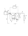
本発明の実施形態について図1、図2を用いて説明する。図1は、本実施形態における蓄熱システムの概略構成図である。本実施形態における蓄熱システムでは、自動車の駆動用エンジンを冷却し、温度が高くなった冷却水の熱を再利用するシステムを一例として説明する。なお、冷却水は不凍液であるLLC(ロングライフクーラント)であるが、これに限られることはなく、水などを用いても良い。以下において、エンジンを冷却し温度が高くなった冷却水を温水とする。   An embodiment of the present invention will be described with reference to FIGS. FIG. 1 is a schematic configuration diagram of a heat storage system in the present embodiment. In the heat storage system in the present embodiment, a system that cools a driving engine of an automobile and reuses heat of cooling water whose temperature has increased will be described as an example. The cooling water is LLC (long life coolant) which is an antifreeze liquid, but is not limited to this, and water or the like may be used. Hereinafter, the cooling water whose temperature has been increased by cooling the engine is referred to as hot water.

蓄熱システムは、エンジン1と、蓄熱器2と、電動ウォーターポンプ3と、乗員室の暖房用のヒーター4と、第1回路5と、第2回路6と、コントローラ7と、エンジン冷却水の熱を放熱するラジエータ(図示せず)とを備える。   The heat storage system includes an engine 1, a heat accumulator 2, an electric water pump 3, a heater 4 for heating a passenger compartment, a first circuit 5, a second circuit 6, a controller 7, and heat of engine cooling water. And a radiator (not shown) for radiating heat.

エンジン1は、燃料を燃焼させて温度が高くなったエンジン本体を冷却する冷却水が流れる冷却部10を備える。   The engine 1 includes a cooling unit 10 through which cooling water flows to cool an engine body whose temperature has been increased by burning fuel.

蓄熱器2について図2を用いて説明する。図2は蓄熱器2の概略断面図である。本実施形態では、鉛直方向に蓄熱器2を配置した場合について説明する。図2においては鉛直方向下向きを矢印yで示す。   The heat accumulator 2 will be described with reference to FIG. FIG. 2 is a schematic cross-sectional view of the heat accumulator 2. In the present embodiment, a case where the heat accumulator 2 is arranged in the vertical direction will be described. In FIG. 2, the downward direction in the vertical direction is indicated by an arrow y.

蓄熱器2は、タンク11と、仕切板12と、可動仕切板13とを備える。蓄熱器2は、例えばエンジン1が停止した際に、次回のエンジン1の始動に備えて温水を貯水する。蓄熱器2に貯水した温水は次回のエンジン1の始動時にエンジン1の冷却部10、ヒーター4に供給される。   The heat accumulator 2 includes a tank 11, a partition plate 12, and a movable partition plate 13. For example, when the engine 1 is stopped, the heat accumulator 2 stores hot water in preparation for the next start of the engine 1. The hot water stored in the heat accumulator 2 is supplied to the cooling unit 10 and the heater 4 of the engine 1 at the next start of the engine 1.

タンク11は第1タンク部15と、第2タンク部16とから構成される。   The tank 11 includes a first tank portion 15 and a second tank portion 16.

第1タンク部15は、直方形であり、下側が開口している。第1タンク部15の側面は、下側で第1開口部17を形成する。   The 1st tank part 15 is a rectangular shape, and the lower side is opening. A side surface of the first tank portion 15 forms a first opening 17 on the lower side.

第2タンク部16は、有底の箱形形状であり、上側が開口している。第2タンク部16の側面は上側で第2開口部18を形成する。第2タンク部16の底面19は、第2開口部18の開口面積よりも面積が小さい。そのため第2タンク部16の側面はテーパ形状となっている。また、第2タンク11は底面19に2つの孔20a、20bを有しており、この孔20a、20bから冷却水が給排される。第1タンク部15の第1開口部17と第2タンク部16の第2開口部18とを合わせて第1タンク部15と第2タンク部16とを接合することで、タンク11が構成される。タンク11は、断熱材(図示せず)で覆われており、蓄熱器2はタンク11からの放熱を抑制している。   The second tank portion 16 has a box shape with a bottom, and the upper side is open. A side surface of the second tank portion 16 forms a second opening 18 on the upper side. The bottom surface 19 of the second tank portion 16 has a smaller area than the opening area of the second opening 18. Therefore, the side surface of the second tank portion 16 is tapered. The second tank 11 has two holes 20a and 20b on the bottom surface 19, and cooling water is supplied and discharged from the holes 20a and 20b. The tank 11 is configured by joining the first tank part 15 and the second tank part 16 together with the first opening part 17 of the first tank part 15 and the second opening part 18 of the second tank part 16. The The tank 11 is covered with a heat insulating material (not shown), and the heat accumulator 2 suppresses heat radiation from the tank 11.

仕切板12は、第2タンク部16の底面19に設けた2つの孔20a、20bの間でタンク11の一部を仕切るように設けられる。なお仕切板12は、タンク11内の上方においては連通口21を形成する。   The partition plate 12 is provided so as to partition a part of the tank 11 between two holes 20 a and 20 b provided in the bottom surface 19 of the second tank portion 16. The partition plate 12 forms a communication port 21 above the tank 11.

可動仕切板13は、有底の箱形形状であり、仕切板12によって仕切られたタンク11内の空間をy方向に垂直な方向で第1の室30と第2の室31とに分ける。本実施形態では、y方向において可動仕切板13よりも下側の空間を第1の室30とし、可動仕切板13よりも上側の空間を第2の室31とする。なお、本実施形態では、仕切板12によって仕切られた空間であり、可動仕切板13を設けていない空間を含めて第2の室31とする。第1の室30は第2タンク11の底面19に設けた孔20aを有しており、第2の室31は第2タンク11の底面19に設けた孔20bを有している。なお、詳しくは後述するが、温水は孔20bを介して第2の室31へ供給される。一方、温水を排出する場合には、孔20aを介して第1の室30へ冷却水を供給し、可動仕切板13をy方向に沿って上方に押し上げることで、第2の室31の温水を排出する。   The movable partition plate 13 has a box shape with a bottom, and divides the space in the tank 11 partitioned by the partition plate 12 into a first chamber 30 and a second chamber 31 in a direction perpendicular to the y direction. In the present embodiment, the space below the movable partition plate 13 in the y direction is the first chamber 30, and the space above the movable partition plate 13 is the second chamber 31. In the present embodiment, the second chamber 31 is a space partitioned by the partition plate 12 and includes a space where the movable partition plate 13 is not provided. The first chamber 30 has a hole 20 a provided in the bottom surface 19 of the second tank 11, and the second chamber 31 has a hole 20 b provided in the bottom surface 19 of the second tank 11. In addition, although mentioned later in detail, warm water is supplied to the 2nd chamber 31 through the hole 20b. On the other hand, when discharging hot water, the cooling water is supplied to the first chamber 30 through the hole 20a, and the movable partition plate 13 is pushed upward along the y direction, whereby the hot water in the second chamber 31 is supplied. Is discharged.

また、可動仕切板13は、側面の外周に沿ってy方向における断面が略半円形状の当接部32を備える。当接部32は、側面の外周に沿って、可動仕切板13の上方と下方の2箇所に設けられる。本実施形態では、当接部32は2箇所に設けられているが、これに限られることはなく、さらに当接部を設けてもよい。当接部32はタンク内壁および仕切板12との摩擦を低減して可撓仕切板13の移動を容易にすると共に可撓仕切り板13の傾きを抑える。   The movable partition plate 13 includes a contact portion 32 having a substantially semicircular cross section in the y direction along the outer periphery of the side surface. The contact portions 32 are provided at two locations above and below the movable partition plate 13 along the outer periphery of the side surface. In this embodiment, the contact part 32 is provided in two places, However, it is not restricted to this, You may provide a contact part further. The contact portion 32 reduces friction between the inner wall of the tank and the partition plate 12 to facilitate the movement of the flexible partition plate 13 and suppresses the inclination of the flexible partition plate 13.

可動仕切板13は、冷却水よりも熱伝導率が低く、体積密度が大きい材料によって構成される。例えば可動仕切板13の材料は、熱伝導率が0.6W/(m・K)よりも低く、体積密度が1100kg/m3以上の材料である。また、可動仕切板13は、タンク11内に温水が貯められている場合に当接部32がタンク11の内壁および仕切板12に当接し、タンク11内に温度が低い冷却水(冷水)が貯められている場合に熱収縮し、当接部32とタンク11の内壁および仕切板12との間に隙間を生じさせる材料によって構成される。なお、当接部32と可動仕切板13の本体とを別の部材で構成しても良い。高温の冷却水が溜められている場合でも冷却水の移動時には可動仕切板13がタンク11内を移動できるように構成されている。 The movable partition plate 13 is made of a material having a lower thermal conductivity and a larger volume density than the cooling water. For example, the material of the movable partition plate 13 is a material having a thermal conductivity lower than 0.6 W / (m · K) and a volume density of 1100 kg / m 3 or more. The movable partition plate 13 has a contact portion 32 that contacts the inner wall of the tank 11 and the partition plate 12 when hot water is stored in the tank 11, and cooling water (cold water) having a low temperature is stored in the tank 11. When stored, it is made of a material that heat-shrinks and creates a gap between the contact portion 32 and the inner wall of the tank 11 and the partition plate 12. In addition, you may comprise the contact part 32 and the main body of the movable partition plate 13 by another member. Even when high-temperature cooling water is stored, the movable partition plate 13 can be moved in the tank 11 when the cooling water is moved.

可動仕切板13は、温度が低くなると熱収縮し、当接部32と、タンク11の内壁および仕切板12との間に高温時より広い隙間を生じさせる。   When the temperature is lowered, the movable partition plate 13 is thermally contracted, and a wider gap is generated between the contact portion 32 and the inner wall of the tank 11 and the partition plate 12 than at a high temperature.

タンク11内に温水を貯水している場合には、第1の室30に冷却水を供給することで、可動仕切板13はy方向に沿って上方へ移動する。このとき当接部32はタンク11の内壁および仕切板12に摺動するので、第2の室31の温水は孔20bを介してタンク11から効率よく排出される。また、高温の冷却水が貯水されているため当接部32とタンク11の内壁および仕切板12との間に冷水が貯留されているときより大きな隙間が生じないので、第1の室30内の温度の低い冷却水が第2の室31へ混入することを防止し、タンク11から排出される温水の温度低下を抑制することができる。   When warm water is stored in the tank 11, the movable partition plate 13 moves upward along the y direction by supplying cooling water to the first chamber 30. At this time, the abutting portion 32 slides on the inner wall of the tank 11 and the partition plate 12, so that the hot water in the second chamber 31 is efficiently discharged from the tank 11 through the hole 20b. Further, since the high-temperature cooling water is stored, there is no larger gap between the abutting portion 32 and the inner wall of the tank 11 and the partition plate 12 than when the cold water is stored. It is possible to prevent the cooling water having a low temperature from entering the second chamber 31 and to suppress the temperature drop of the hot water discharged from the tank 11.

タンク11から温水を排出すると、タンク11内は温度が低い冷却水の量が多くなる。そのため、可動仕切板13は熱収縮し、当接部32とタンク11の内壁および仕切板12との間に温水貯水時に比べて大きな隙間を生じさせ、可動仕切板13は自重によりy方向に沿って下方へ移動する。   When hot water is discharged from the tank 11, the amount of cooling water having a low temperature increases in the tank 11. Therefore, the movable partition plate 13 is thermally contracted, and a large gap is generated between the abutting portion 32 and the inner wall of the tank 11 and the partition plate 12 as compared with the time of storing hot water. Move downward.

可動仕切板13の高さh1は、連通口21の高さh2よりも高い。可動仕切板13の高さh1を連通口21の高さh2よりも高くすることで、可動仕切板13が連通口21に進入することを防止することができる。   The height h1 of the movable partition plate 13 is higher than the height h2 of the communication port 21. By making the height h <b> 1 of the movable partition plate 13 higher than the height h <b> 2 of the communication port 21, it is possible to prevent the movable partition plate 13 from entering the communication port 21.

また、可動仕切板13は、底面35に底面35を貫通する孔33と可動弁34とを備える。可動弁34は、孔33を塞ぐように設けられ、可動弁34の上方の水圧が可動弁34の下方の水圧よりも所定圧以上大きくなると開く。所定圧は予め定められた圧である。そして、図2のような構造では、テーパ部によって底面19と可動仕切板13との間に可動弁34の作動分の隙間を生じるようになっている。そのほか、可動仕切り板13から突起を出して、底面19と隙間を生じるようにしても良い。これにより、温水の導入時に冷水との入れ替わりが速やかに行われる。   The movable partition plate 13 includes a hole 33 that penetrates the bottom surface 35 and a movable valve 34 on the bottom surface 35. The movable valve 34 is provided so as to close the hole 33, and opens when the water pressure above the movable valve 34 is greater than the water pressure below the movable valve 34 by a predetermined pressure. The predetermined pressure is a predetermined pressure. In the structure as shown in FIG. 2, a gap corresponding to the operation of the movable valve 34 is generated between the bottom surface 19 and the movable partition plate 13 by the tapered portion. In addition, a protrusion may be protruded from the movable partition plate 13 so as to form a gap with the bottom surface 19. Thereby, at the time of introduction | transduction of warm water, replacement | exchange with cold water is performed rapidly.

ヒーター4は、図示しない空調装置において温水の熱によってヒーター4のチューブ間を通過する空気を温め、温めた空気を車内へ供給し、車内を温める。   The heater 4 warms the air passing between the tubes of the heater 4 by the heat of hot water in an air conditioner (not shown), supplies the warmed air to the interior of the vehicle, and warms the interior of the vehicle.

第1回路5は、エンジン1の冷却部10とヒーター4とを接続する。第1回路5によって冷却水はエンジン1の冷却部10とヒーター4との間を循環する。エンジン1を冷却することで温度が高くなった冷却水は第1回路5によってヒーター4に供給される。   The first circuit 5 connects the cooling unit 10 of the engine 1 and the heater 4. The first circuit 5 circulates cooling water between the cooling unit 10 of the engine 1 and the heater 4. The cooling water whose temperature has been increased by cooling the engine 1 is supplied to the heater 4 by the first circuit 5.

第2回路6は、蓄熱器2を第1回路5に接続する。電動ウォーターポンプ3は、第2回路6に設けられる。また第2回路6は、電動ウォーターポンプ3をバイパスするバイパス路40を備える。エンジン1の停止後に、電動ウォーターポンプ3を駆動し第2回路6には温水が流れ、第2回路6を介して蓄熱器2に温水が貯水される。また、エンジン1の始動時に、第2回路6を介して蓄熱器2の温水がヒーター4、エンジン1へ供給される。   The second circuit 6 connects the heat accumulator 2 to the first circuit 5. The electric water pump 3 is provided in the second circuit 6. The second circuit 6 includes a bypass path 40 that bypasses the electric water pump 3. After the engine 1 is stopped, the electric water pump 3 is driven, hot water flows through the second circuit 6, and the hot water is stored in the heat accumulator 2 through the second circuit 6. Further, when the engine 1 is started, hot water from the heat accumulator 2 is supplied to the heater 4 and the engine 1 via the second circuit 6.

バイパス路40は、三方弁41を介して第2回路6と接続する。また、第1回路5と第2回路6とは三方弁42によって接続する。   The bypass path 40 is connected to the second circuit 6 via the three-way valve 41. The first circuit 5 and the second circuit 6 are connected by a three-way valve 42.

電動ウォーターポンプ3は、エンジンキースイッチの信号によりエンジン停止を感知して、温水を蓄熱器2へ供給する。   The electric water pump 3 senses engine stop by the signal of the engine key switch and supplies hot water to the heat accumulator 2.

コントローラ7は、三方弁41、42を切り替え、電動ウォーターポンプ3を制御することで冷却水の流れを制御する。   The controller 7 controls the flow of the cooling water by switching the three-way valves 41 and 42 and controlling the electric water pump 3.

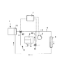
次に本実施形態の作用について図3、4を用いて説明する。図3は蓄熱器2に温水を貯水する場合の冷却水の流れを示す図である。図4は蓄熱器2から温水を排出する場合の冷却水の流れを示す図である。図3、4においては冷却水の流れを矢印で示す。なお、エンジン1の停止時、始動時以外の通常の運転時にヒーター4を作動させる場合には、冷却水は第1回路5を循環する。   Next, the operation of this embodiment will be described with reference to FIGS. FIG. 3 is a diagram showing the flow of cooling water when warm water is stored in the heat accumulator 2. FIG. 4 is a diagram showing the flow of cooling water when warm water is discharged from the heat accumulator 2. 3 and 4, the flow of the cooling water is indicated by arrows. When the heater 4 is operated during normal operation other than when the engine 1 is stopped or started, the cooling water circulates through the first circuit 5.

蓄熱器2に温水を貯水する場合には、エンジン1が停止すると電動ウォーターポンプ3が作動する。また、三方弁41によって電動ウォーターポンプ3と蓄熱器2とが連通し、三方弁42によって第1回路5と第2回路6とが連通する。   When hot water is stored in the heat accumulator 2, the electric water pump 3 is activated when the engine 1 is stopped. Further, the electric water pump 3 and the heat accumulator 2 communicate with each other by the three-way valve 41, and the first circuit 5 and the second circuit 6 communicate with each other by the three-way valve 42.

これによって、温水は、第2回路6、孔20bを介して第2の室31に供給される。第2の室31に温水が流入することで、第2の室31の水圧が高くなる。そして、可動仕切板13の上側の水圧が可動仕切板13の下側の水圧よりも所定圧以上高くなると可動弁34が開き、第2の室31にあった温度の低い冷却水が孔33、20aを介して蓄熱器2から排出される。これによって第2の室31に温水が貯水される。   Accordingly, the hot water is supplied to the second chamber 31 via the second circuit 6 and the hole 20b. When the hot water flows into the second chamber 31, the water pressure in the second chamber 31 increases. When the water pressure on the upper side of the movable partition plate 13 becomes higher than the water pressure on the lower side of the movable partition plate 13 by a predetermined pressure or more, the movable valve 34 is opened, and the cooling water having a low temperature in the second chamber 31 is formed in the holes 33, It is discharged from the heat accumulator 2 through 20a. As a result, warm water is stored in the second chamber 31.

また、蓄熱器2から温水を排出し、エンジン1などを暖機する場合には、エンジン1が始動すると、三方弁42によって第1回路5と第2回路6とを連通する。また、三方弁41によって第2回路6とバイパス通路40とを連通する。これによって孔20aを介して第1の室30に冷却水が供給される。第1の室30に供給された冷却水は、可動仕切板13を上方に押し上げる。このとき第2の室31には温水が貯水されているので、可動仕切板13の当接部32がタンク11の内壁および仕切板12に当接又は微細な隙間を有してしている。そのため、可動仕切板13は、タンク11の内壁および仕切板12に摺動し、上方へ移動する。これによって、第2の室31内の温水が孔20bを介して蓄熱器2から排出される。蓄熱器2から排出される温水をエンジン1などに供給することで、始動時の暖機を素早く行うことができる。なお、エンジン1が駆動している場合には、クランクシャフトの回転などによって動作するウォーターポンプなどによって冷却水は第1回路5などを流れる。   When warm water is discharged from the heat accumulator 2 and the engine 1 is warmed up, the first circuit 5 and the second circuit 6 are communicated by the three-way valve 42 when the engine 1 is started. Further, the second circuit 6 and the bypass passage 40 are communicated by the three-way valve 41. Thereby, the cooling water is supplied to the first chamber 30 through the hole 20a. The cooling water supplied to the first chamber 30 pushes up the movable partition plate 13 upward. At this time, since warm water is stored in the second chamber 31, the contact portion 32 of the movable partition plate 13 is in contact with the inner wall of the tank 11 and the partition plate 12 or has a fine gap. Therefore, the movable partition plate 13 slides on the inner wall of the tank 11 and the partition plate 12 and moves upward. Thereby, the hot water in the second chamber 31 is discharged from the heat accumulator 2 through the hole 20b. By supplying the hot water discharged from the heat accumulator 2 to the engine 1 or the like, warm-up at the time of starting can be performed quickly. Note that when the engine 1 is driven, the cooling water flows through the first circuit 5 and the like by a water pump or the like that operates by rotation of the crankshaft or the like.

なお、蓄熱器2は整流板、可動仕切板13のy方向への移動をガイドするガイド部材を設け、可動仕切板13がタンク11内で傾くことを抑制しても良い。ガイド部材としては、例えば可動仕切板13を貫通する貫通棒である。   Note that the heat accumulator 2 may be provided with a guide member that guides the movement of the rectifying plate and the movable partition plate 13 in the y direction so that the movable partition plate 13 is prevented from being inclined in the tank 11. As a guide member, it is a penetration stick which penetrates movable partition plate 13, for example.

本実施形態では、エンジン1の冷却部10とヒーター4とを接続する第1回路5に、第2回路6によって蓄熱器2を接続したが、これに限られることはない。   In the present embodiment, the heat accumulator 2 is connected by the second circuit 6 to the first circuit 5 that connects the cooling unit 10 of the engine 1 and the heater 4, but is not limited thereto.

本実施形態では、エンジン1の停止時に蓄熱器2に温水を貯水したが、エンジンの駆動時に例えば所定時間毎に蓄熱器2へ温水を貯水しても良い。   In the present embodiment, warm water is stored in the heat accumulator 2 when the engine 1 is stopped, but hot water may be stored in the heat accumulator 2 every predetermined time when the engine is driven.

また、タンク11の形状、可動仕切板13の形状は本実施形態の形状に限られることはなく、例えばタンクの形状を円柱形状としてもよい。   Moreover, the shape of the tank 11 and the shape of the movable partition plate 13 are not limited to the shape of this embodiment, For example, the shape of the tank may be a columnar shape.

本発明の実施形態の効果について説明する。   The effect of the embodiment of the present invention will be described.

可動仕切板13に断面が略半円形状の当接部32を設けることによって、当接部32とタンク11の内壁および仕切板12との接触が線接触となり、可動仕切板13がタンク11に引っ掛かることを抑制し、可動仕切板13を速やかに移動させることができる。そのため、タンク11内の温水を速やかにタンク11から排出することができ、例えばエンジン1などの暖機を素早く行うことができる。エンジンオイルの粘性を下げることで、摩擦を減らし燃費向上につながる。また、温水を排出する場合に、当接部32をタンク11の内壁および仕切板12に摺動させることで、温度の低い冷却水が温水と混ざることを防止することができ、温水の温度低下を抑制することができる。   By providing the movable partition plate 13 with the contact portion 32 having a substantially semicircular cross section, the contact between the contact portion 32 and the inner wall of the tank 11 and the partition plate 12 becomes a line contact, and the movable partition plate 13 is attached to the tank 11. The movable partition plate 13 can be quickly moved while restrained from being caught. Therefore, the warm water in the tank 11 can be quickly discharged from the tank 11, and for example, the engine 1 and the like can be warmed up quickly. Lowering the viscosity of engine oil reduces friction and improves fuel efficiency. Moreover, when discharging warm water, the contact part 32 is made to slide on the inner wall and the partition plate 12 of the tank 11, and it can prevent that a cooling water with low temperature is mixed with warm water, and the temperature of warm water falls. Can be suppressed.

可動仕切板13を冷却水よりも熱伝導率が低い材料で構成することで、タンク11に温水を貯水した場合に、温水の温度低下を抑制することができる。   By configuring the movable partition plate 13 with a material having a lower thermal conductivity than that of the cooling water, when the hot water is stored in the tank 11, the temperature drop of the hot water can be suppressed.

また、可動仕切板13を冷却水よりも体積密度が大きい材料で構成することで、冷水である冷却水を導入しタンク11から温水を排出した後に、可動仕切板13の自重により可動仕切板13を下側に移動させることができる。そのため、モータなどを使用せずに可動仕切板13を下側に移動させることができる。冷水によって収縮することにより、可動仕切板13とタンク11および仕切板12との隙間が大きくなるためよりスムースに下側への移動ができる。   In addition, by configuring the movable partition plate 13 with a material having a volume density larger than that of the cooling water, after introducing the cooling water that is cold water and discharging the warm water from the tank 11, the movable partition plate 13 is caused by its own weight. Can be moved downward. Therefore, the movable partition plate 13 can be moved downward without using a motor or the like. By contracting with cold water, the gap between the movable partition plate 13 and the tank 11 and the partition plate 12 is increased, so that the lower partition can be moved more smoothly.

当接部32を可動仕切板13の外周に沿って上下2箇所に設けることで、可動仕切板13がタンク11内で移動する際に安定して移動させることができる。   By providing the abutting portions 32 at two locations above and below the outer periphery of the movable partition plate 13, the movable partition plate 13 can be stably moved when moving in the tank 11.

可動仕切板13を有底の箱形形状とすることで、タンク11内に温水を多く貯水することができ、可動仕切板13を移動させる際に安定して移動させることができる。   By making the movable partition plate 13 into a box shape with a bottom, a large amount of hot water can be stored in the tank 11 and can be moved stably when the movable partition plate 13 is moved.

本発明は上記した実施形態に限定されるものではなく、その技術的思想の範囲内でなしうるさまざまな変更、改良が含まれることは言うまでもない。   It goes without saying that the present invention is not limited to the above-described embodiments, and includes various modifications and improvements that can be made within the scope of the technical idea.

1 エンジン
2 蓄熱器
3 電動ウォーターポンプ
13 可動仕切板
30 第1の室
31 第2の室
32 当接部
33 孔
34 可動弁
DESCRIPTION OF SYMBOLS 1 Engine 2 Heat accumulator 3 Electric water pump 13 Movable partition plate 30 1st chamber 31 2nd chamber 32 Contact part 33 Hole 34 Movable valve

Claims (4)

温水をタンクに貯水する蓄熱器において、
前記タンク内を第1の室と第2の室とに分け、前記タンク内を移動することで前記第1の室および前記第2の室の体積を変更し、前記タンク内の温水を前記タンクから排出する可動仕切板を備え、
前記可動仕切板は、前記タンク内に温水を貯水している場合に冷水を貯水しているときより狭い隙間で前記タンクの内壁に当接する当接部を有し、
前記当接部は、前記温水を前記タンクから排出する場合には前記タンクの内壁に摺動することを特徴とする蓄熱器。
In a regenerator that stores hot water in a tank,
The tank is divided into a first chamber and a second chamber, and the volumes of the first chamber and the second chamber are changed by moving in the tank, and hot water in the tank is supplied to the tank. Equipped with a movable partition plate that discharges from
The movable partition plate has a contact portion that contacts the inner wall of the tank with a narrower gap when storing cold water when storing hot water in the tank,
The contact portion slides on the inner wall of the tank when the hot water is discharged from the tank.
前記可動仕切板は、前記温水よりも熱伝導率が低く、かつ前記温水よりも体積密度が大きいことを特徴とする請求項1に記載の蓄熱器。   The regenerator according to claim 1, wherein the movable partition plate has a thermal conductivity lower than that of the hot water and a volume density higher than that of the hot water. 前記当接部は、前記移動方向に複数設けられることを特徴とする請求項1または2に記載の蓄熱器。   The heat accumulator according to claim 1, wherein a plurality of the contact portions are provided in the moving direction. 前記可動仕切板は有底の箱形形状であることを特徴とする請求項1から3のいずれか一つに記載の蓄熱器。   The regenerator according to any one of claims 1 to 3, wherein the movable partition plate has a bottomed box shape.
JP2009262627A 2009-11-18 2009-11-18 Heat accumulator Withdrawn JP2011106351A (en)

Priority Applications (1)

Application Number Priority Date Filing Date Title
JP2009262627A JP2011106351A (en) 2009-11-18 2009-11-18 Heat accumulator

Applications Claiming Priority (1)

Application Number Priority Date Filing Date Title
JP2009262627A JP2011106351A (en) 2009-11-18 2009-11-18 Heat accumulator

Publications (1)

Publication Number Publication Date
JP2011106351A true JP2011106351A (en) 2011-06-02

Family

ID=44230095

Family Applications (1)

Application Number Title Priority Date Filing Date
JP2009262627A Withdrawn JP2011106351A (en) 2009-11-18 2009-11-18 Heat accumulator

Country Status (1)

Country Link
JP (1) JP2011106351A (en)

Cited By (2)

* Cited by examiner, † Cited by third party
Publication number Priority date Publication date Assignee Title
CN111963295A (en) * 2020-08-11 2020-11-20 安庆中船柴油机有限公司 Closed cooling circulating water cooling system of marine diesel engine
CN115075930A (en) * 2022-06-27 2022-09-20 江苏徐工国重实验室科技有限公司 Engineering machinery cooling system and control method

Cited By (3)

* Cited by examiner, † Cited by third party
Publication number Priority date Publication date Assignee Title
CN111963295A (en) * 2020-08-11 2020-11-20 安庆中船柴油机有限公司 Closed cooling circulating water cooling system of marine diesel engine
CN115075930A (en) * 2022-06-27 2022-09-20 江苏徐工国重实验室科技有限公司 Engineering machinery cooling system and control method
CN115075930B (en) * 2022-06-27 2023-05-30 江苏徐工国重实验室科技有限公司 Engineering machinery cooling system and control method

Similar Documents

Publication Publication Date Title
US20090236435A1 (en) Warming-up system for vehicle
KR20180099007A (en) Coolant Reservoir Tank for Vehicle
JP2011106351A (en) Heat accumulator
US20060070589A1 (en) Heat storage tank with improved heat insulating performance
JP4929692B2 (en) Fuel cell cooling system
JP2006077696A (en) Two-tank type oil pan
JP2006329069A (en) Engine and cooling medium treating device
JP2019124392A (en) Heat storage device
JP2008106613A (en) Warming-up device for drive source
JP2009270757A (en) Heat accumulator
JP2006183943A (en) Accumulator
JP4408243B2 (en) Mold temperature controller
KR100589146B1 (en) engine cooling system
KR20090013229U (en) Radiator tank united with Reservoir tank
JP6214447B2 (en) Catalytic converter cooling mechanism
KR102092795B1 (en) Transmission Oil Heat Exchanger
JP2009103048A (en) Engine cooling system
JP6638778B2 (en) Engine temperature control system
JP2010038037A (en) Reservoir tank
JP2009121319A (en) Engine cooling device and operating method of the same
JP2008248741A (en) Warming-up device for internal combustion engine
JP2009085130A (en) Cooling device for vehicular engine
JP2006144663A (en) Controller of temperature around oil pan
KR102552549B1 (en) Cooling device
JP2010265765A (en) Vehicle warming up system and heat accumulator for vehicle warming up used therefor

Legal Events

Date Code Title Description
A621 Written request for application examination

Free format text: JAPANESE INTERMEDIATE CODE: A621

Effective date: 20120920

A761 Written withdrawal of application

Free format text: JAPANESE INTERMEDIATE CODE: A761

Effective date: 20130801

A977 Report on retrieval

Free format text: JAPANESE INTERMEDIATE CODE: A971007

Effective date: 20130808