JP2011099442A - Device for cooling generator - Google Patents
Device for cooling generator Download PDFInfo
- Publication number
- JP2011099442A JP2011099442A JP2010248891A JP2010248891A JP2011099442A JP 2011099442 A JP2011099442 A JP 2011099442A JP 2010248891 A JP2010248891 A JP 2010248891A JP 2010248891 A JP2010248891 A JP 2010248891A JP 2011099442 A JP2011099442 A JP 2011099442A
- Authority
- JP
- Japan
- Prior art keywords
- cooling
- stator
- cooling pipe
- generator
- laminate
- Prior art date
- Legal status (The legal status is an assumption and is not a legal conclusion. Google has not performed a legal analysis and makes no representation as to the accuracy of the status listed.)
- Pending
Links
Images


Classifications
-
- F—MECHANICAL ENGINEERING; LIGHTING; HEATING; WEAPONS; BLASTING
- F03—MACHINES OR ENGINES FOR LIQUIDS; WIND, SPRING, OR WEIGHT MOTORS; PRODUCING MECHANICAL POWER OR A REACTIVE PROPULSIVE THRUST, NOT OTHERWISE PROVIDED FOR
- F03D—WIND MOTORS
- F03D80/00—Details, components or accessories not provided for in groups F03D1/00 - F03D17/00
- F03D80/60—Cooling or heating of wind motors
-
- F—MECHANICAL ENGINEERING; LIGHTING; HEATING; WEAPONS; BLASTING
- F03—MACHINES OR ENGINES FOR LIQUIDS; WIND, SPRING, OR WEIGHT MOTORS; PRODUCING MECHANICAL POWER OR A REACTIVE PROPULSIVE THRUST, NOT OTHERWISE PROVIDED FOR
- F03D—WIND MOTORS
- F03D9/00—Adaptations of wind motors for special use; Combinations of wind motors with apparatus driven thereby; Wind motors specially adapted for installation in particular locations
- F03D9/20—Wind motors characterised by the driven apparatus
- F03D9/25—Wind motors characterised by the driven apparatus the apparatus being an electrical generator
-
- H—ELECTRICITY
- H02—GENERATION; CONVERSION OR DISTRIBUTION OF ELECTRIC POWER
- H02K—DYNAMO-ELECTRIC MACHINES
- H02K1/00—Details of the magnetic circuit
- H02K1/06—Details of the magnetic circuit characterised by the shape, form or construction
- H02K1/12—Stationary parts of the magnetic circuit
- H02K1/20—Stationary parts of the magnetic circuit with channels or ducts for flow of cooling medium
-
- H—ELECTRICITY
- H02—GENERATION; CONVERSION OR DISTRIBUTION OF ELECTRIC POWER
- H02K—DYNAMO-ELECTRIC MACHINES
- H02K9/00—Arrangements for cooling or ventilating
- H02K9/19—Arrangements for cooling or ventilating for machines with closed casing and closed-circuit cooling using a liquid cooling medium, e.g. oil
- H02K9/197—Arrangements for cooling or ventilating for machines with closed casing and closed-circuit cooling using a liquid cooling medium, e.g. oil in which the rotor or stator space is fluid-tight, e.g. to provide for different cooling media for rotor and stator
-
- F—MECHANICAL ENGINEERING; LIGHTING; HEATING; WEAPONS; BLASTING
- F05—INDEXING SCHEMES RELATING TO ENGINES OR PUMPS IN VARIOUS SUBCLASSES OF CLASSES F01-F04
- F05B—INDEXING SCHEME RELATING TO WIND, SPRING, WEIGHT, INERTIA OR LIKE MOTORS, TO MACHINES OR ENGINES FOR LIQUIDS COVERED BY SUBCLASSES F03B, F03D AND F03G
- F05B2260/00—Function
- F05B2260/20—Heat transfer, e.g. cooling
- F05B2260/201—Heat transfer, e.g. cooling by impingement of a fluid
-
- H—ELECTRICITY
- H02—GENERATION; CONVERSION OR DISTRIBUTION OF ELECTRIC POWER
- H02K—DYNAMO-ELECTRIC MACHINES
- H02K1/00—Details of the magnetic circuit
- H02K1/06—Details of the magnetic circuit characterised by the shape, form or construction
- H02K1/12—Stationary parts of the magnetic circuit
- H02K1/16—Stator cores with slots for windings
-
- H—ELECTRICITY
- H02—GENERATION; CONVERSION OR DISTRIBUTION OF ELECTRIC POWER
- H02K—DYNAMO-ELECTRIC MACHINES
- H02K2213/00—Specific aspects, not otherwise provided for and not covered by codes H02K2201/00 - H02K2211/00
- H02K2213/12—Machines characterised by the modularity of some components
-
- H—ELECTRICITY
- H02—GENERATION; CONVERSION OR DISTRIBUTION OF ELECTRIC POWER
- H02K—DYNAMO-ELECTRIC MACHINES
- H02K7/00—Arrangements for handling mechanical energy structurally associated with dynamo-electric machines, e.g. structural association with mechanical driving motors or auxiliary dynamo-electric machines
- H02K7/18—Structural association of electric generators with mechanical driving motors, e.g. with turbines
- H02K7/1807—Rotary generators
- H02K7/1823—Rotary generators structurally associated with turbines or similar engines
- H02K7/183—Rotary generators structurally associated with turbines or similar engines wherein the turbine is a wind turbine
- H02K7/1838—Generators mounted in a nacelle or similar structure of a horizontal axis wind turbine
-
- Y—GENERAL TAGGING OF NEW TECHNOLOGICAL DEVELOPMENTS; GENERAL TAGGING OF CROSS-SECTIONAL TECHNOLOGIES SPANNING OVER SEVERAL SECTIONS OF THE IPC; TECHNICAL SUBJECTS COVERED BY FORMER USPC CROSS-REFERENCE ART COLLECTIONS [XRACs] AND DIGESTS
- Y02—TECHNOLOGIES OR APPLICATIONS FOR MITIGATION OR ADAPTATION AGAINST CLIMATE CHANGE
- Y02E—REDUCTION OF GREENHOUSE GAS [GHG] EMISSIONS, RELATED TO ENERGY GENERATION, TRANSMISSION OR DISTRIBUTION
- Y02E10/00—Energy generation through renewable energy sources
- Y02E10/70—Wind energy
- Y02E10/72—Wind turbines with rotation axis in wind direction
-
- Y—GENERAL TAGGING OF NEW TECHNOLOGICAL DEVELOPMENTS; GENERAL TAGGING OF CROSS-SECTIONAL TECHNOLOGIES SPANNING OVER SEVERAL SECTIONS OF THE IPC; TECHNICAL SUBJECTS COVERED BY FORMER USPC CROSS-REFERENCE ART COLLECTIONS [XRACs] AND DIGESTS
- Y02—TECHNOLOGIES OR APPLICATIONS FOR MITIGATION OR ADAPTATION AGAINST CLIMATE CHANGE
- Y02T—CLIMATE CHANGE MITIGATION TECHNOLOGIES RELATED TO TRANSPORTATION
- Y02T50/00—Aeronautics or air transport
- Y02T50/60—Efficient propulsion technologies, e.g. for aircraft
Abstract
Description
本発明は、好適には風車において使用される発電機の冷却のための装置に関する。 The present invention preferably relates to an apparatus for cooling a generator used in a windmill.
風車における発電機の運転中、ロータによって磁界が誘発される。ロータは、永久磁石又は巻線形磁極を有しており、これらは、ステータコア及びステータコイルに磁界を誘発する。これによって、電流が誘発され、この電流はステータコア及びステータコイルに大きな熱を発生する。 During operation of the generator in the windmill, a magnetic field is induced by the rotor. The rotor has permanent magnets or wound poles that induce magnetic fields in the stator core and the stator coil. This induces an electric current that generates a large amount of heat in the stator core and the stator coil.
付加的な渦電流は熱の発生に寄与する。導体と磁界力との相対運動による変化する磁界に導体が曝されると、渦電流が発生する。渦電流は、時間の経過に伴う磁界の変化によっても発生される。 The additional eddy current contributes to heat generation. When the conductor is exposed to a magnetic field that changes due to the relative motion between the conductor and the magnetic field force, an eddy current is generated. Eddy currents are also generated by changes in the magnetic field over time.
渦電流は、ステータ構成部材とロータ構成部材との間の所望の磁界に対抗する磁界を発生する。これは、渦電流損失を生ぜしめる。 Eddy currents generate a magnetic field that opposes the desired magnetic field between the stator and rotor components. This causes eddy current loss.
渦電流損失は、特に風車における直接駆動発電機のような大型電気機械の場合、著しいレベルに達することがある。すなわち、ロータの効率が減じられる。 Eddy current losses can reach significant levels, especially for large electrical machines such as direct drive generators in wind turbines. That is, the efficiency of the rotor is reduced.
さらに、渦電流によって発生された熱は、ステータ構成部材における温度を上昇させる。 Furthermore, the heat generated by the eddy current raises the temperature in the stator component.
典型的なステータは、金属から形成された積み重ねられた積層板を有する。積層板は、例えば鉄のシートから打ち抜かれている。 A typical stator has stacked laminates formed from metal. The laminated plate is punched from, for example, an iron sheet.
図9は、発電機におけるステータの一部である公知の積層板LPの形状を示している。 FIG. 9 shows the shape of a known laminated plate LP which is a part of the stator in the generator.
積層板LPの第1の側S1は、発電機のステータとロータとの間の空隙に向けられている。この第1の側S1には、多数のスロットSLが設けられている。スロットSLは、好適には積層板LPから打ち抜かれている。 The first side S1 of the laminate plate LP is directed to the gap between the stator and the rotor of the generator. A number of slots SL are provided on the first side S1. The slot SL is preferably punched out from the laminate LP.
多数の積層板LPが積み重ねられ、これにより、スロットSLは積み重ねられた積層板L内にチャネルCHを形成する。チャネルCHは、ステータコイルの金属巻線MWを支持している。 A number of laminates LP are stacked, whereby the slots SL form channels CH in the stacked laminates L. The channel CH supports the metal winding MW of the stator coil.
それぞれの金属巻線MWは、導体CONによって形成されており、この導体CONは、導体絶縁体CONIによって包囲されている。それぞれのスロットSLは、金属巻線MWを絶縁するためにスロット絶縁ライニングSILを有している。 Each metal winding MW is formed by a conductor CON, and this conductor CON is surrounded by a conductor insulator CONI. Each slot SL has a slot insulation lining SIL to insulate the metal winding MW.
スロットSLのそれぞれの上部には凹所RCが設けられている。凹所RCは、くさび形部材WDGを支持するように構成されている。くさび形部材WDGによって、挿入された金属巻線MWは所定の位置に保持される。 A recess RC is provided in each upper portion of the slot SL. The recess RC is configured to support the wedge-shaped member WDG. The inserted metal winding MW is held at a predetermined position by the wedge-shaped member WDG.
電気機械が作動していると、熱が発生される。熱は、主にステータの金属巻線MWによって発生される。熱により、金属巻線MWの絶縁体が損傷されることがあり、従って、巻線の温度は、電気機械の所定の寿命を達成するために低下させる必要がある。 When the electric machine is operating, heat is generated. Heat is mainly generated by the stator metal winding MW. Heat can damage the insulation of the metal winding MW, and thus the temperature of the winding needs to be lowered to achieve a predetermined life of the electric machine.
大型の電気機械を冷却するために様々な装置及び方法が知られている。極めて一般的なものは、電気機械の内部での空気等の気体媒体の循環である。この気体媒体は、例えば熱交換によって低温に保たれる。 Various devices and methods are known for cooling large electrical machines. Very common is the circulation of a gaseous medium such as air inside an electric machine. This gaseous medium is kept at a low temperature by, for example, heat exchange.
この方法の欠点は、大きなガス対空気又はガス対水式の熱交換器が必要とされることである。さらに、冷却媒体を循環させるために付加的な電力が必要とされる。 The disadvantage of this method is that a large gas-to-air or gas-to-water heat exchanger is required. In addition, additional power is required to circulate the cooling medium.
別の一般的な方法は、空隙に隣接していない又は空隙に面していない、ステータ側において冷却液を循環させることである。つまり、熱は、金属巻線から伝導によって積層板へ伝達され、積層板から伝導によって冷却液に伝達される。 Another common method is to circulate coolant on the stator side that is not adjacent to or facing the air gap. That is, heat is transferred from the metal winding to the laminated plate by conduction, and is transferred from the laminated plate to the coolant by conduction.
この方法の欠点は、積層鉄の適度な熱伝導率により、ステータ巻線と冷却媒体との間にかなりの温度勾配が存在するということである。従って、巻線の温度を所要の最大値よりも低く維持することが困難である。 The disadvantage of this method is that due to the moderate thermal conductivity of the laminated iron, there is a considerable temperature gradient between the stator windings and the cooling medium. Therefore, it is difficult to maintain the temperature of the winding below the required maximum value.
別の一般的な方法は、液体又は気体媒体を中空の銅バーに導入することである。これらのバーは、ステータコイルの巻線の下側に装着されているか又は、積み重ねられた積層板の裏側に溶接によって結合されている。銅バーは、積層板のチャネルを超えている。 Another common method is to introduce a liquid or gaseous medium into the hollow copper bar. These bars are mounted on the underside of the stator coil windings or are joined by welding to the backside of the stacked laminates. The copper bar is beyond the channel of the laminate.
この方法の欠点は、電気接続のために及び中空銅バーの結合のために、多数の接合部が必要とされることである。したがって、この方法は、極めて大型の発電機においてのみ使用される。 The disadvantage of this method is that a large number of joints are required for electrical connection and for bonding of hollow copper bars. This method is therefore only used in very large generators.
別の欠点は、冷却管が、コイル巻線と同じ電磁界に曝され、これにより、金属から形成された冷却管に電圧が誘発されることである。 Another disadvantage is that the cooling tube is exposed to the same electromagnetic field as the coil winding, which induces a voltage in the cooling tube formed from metal.
別の方法は、米国特許出願公開第2005/0067904号明細書から知られている。この場合、鉄から形成されたステータ積層体は、ロータとは反対側を向いたステータ側においてC字形スロットを有している。冷却管は、前記スロットに挿入されており、管は、C字形チャネルに合致するように変形させられる。 Another method is known from US 2005/0067904. In this case, the stator stack formed of iron has a C-shaped slot on the stator side facing away from the rotor. A cooling tube is inserted into the slot and the tube is deformed to match the C-shaped channel.
この方法の欠点は、冷却管の変形が管に小さなき裂を生じる恐れがあることである。これらのき裂は、例えば腐食、環境的影響又は材料特性により、次第に拡大する恐れがある。つまり、き裂は、後に漏れを生じる。 The disadvantage of this method is that deformation of the cooling tube can cause small cracks in the tube. These cracks can gradually expand due to, for example, corrosion, environmental influences or material properties. That is, the crack will later leak.
この方法の別の欠点は、この方法が大型の電気機械において使用されると、冷却管の長さが増大するということである。この場合、冷却管は、長い"蛇行状"に成形される。長い蛇行状の管を流れる間に冷却液は加熱される。従って、蛇行の主な部分を含むステータの区分は、十分に冷却されなくなる。さらに、例えば鉄から形成されたステータ積層体に、温度勾配が生じる。 Another disadvantage of this method is that the length of the cooling tube increases when this method is used in large electric machines. In this case, the cooling pipe is shaped into a long “meander”. The coolant is heated while flowing through the long serpentine tube. Therefore, the section of the stator that contains the main part of the meander will not be sufficiently cooled. Furthermore, a temperature gradient is generated in a stator laminate formed of, for example, iron.
したがって、本発明の課題は、特に風車における直接駆動発電機のような大型の電気機械のための、発電機のための改良された冷却装置を提供することである。 The object of the present invention is therefore to provide an improved cooling device for generators, especially for large electric machines such as direct drive generators in wind turbines.
前記課題は、請求項1の特徴によって達成される。さらに、発明の構成は従属請求項の主体である。
The object is achieved by the features of
本発明の装置は、ロータ及びステータを有する発電機に関する。ステータは、少なくとも2つのステータセグメントを有する。ステータセグメントのうちの少なくとも1つは、多数の積み重ねられた積層板を有している。積み重ねられた積層板は、第1の側に多数のスロットを有しており、積み重ねられた積層板の第1の側は、ロータに整合させられている。スロットは、ステータコイルの金属巻線を支持している。冷却管内に配置された冷却媒体によって積層板を冷却するために、ステータセグメントの積み重ねられた積層板には、少なくとも1つの中空冷却管が部分的に一体化されている。 The apparatus of the present invention relates to a generator having a rotor and a stator. The stator has at least two stator segments. At least one of the stator segments has a number of stacked laminates. The stacked laminate has a number of slots on the first side, and the first side of the stacked laminate is aligned with the rotor. The slot supports the metal winding of the stator coil. At least one hollow cooling tube is partly integrated in the stacked laminate of stator segments in order to cool the laminate with a cooling medium arranged in the cooling tube.
ステータは、セグメントに分割されている。好適には、部分的に一体化された冷却管は、専用の冷却管と一緒に少なくとも1つのステータセグメントを交換することができるように設計されている。 The stator is divided into segments. Preferably, the partially integrated cooling tube is designed such that at least one stator segment can be replaced with a dedicated cooling tube.
冷却管の表面の大部分はステータに一体化されているので、冷却管の表面は、ステータセグメントと密に接触している。従って、熱伝導が高められる。これは、専用のセグメントの最適な冷却を保証する。 Since most of the surface of the cooling tube is integrated with the stator, the surface of the cooling tube is in intimate contact with the stator segment. Therefore, heat conduction is increased. This ensures optimal cooling of the dedicated segment.
ステータセグメントにおける渦電流は、冷却管の配置と、冷却管のために使用される材料とにより、冷却管の周囲において排除される。 Eddy currents in the stator segment are rejected around the cooling pipe due to the arrangement of the cooling pipe and the material used for the cooling pipe.
減じられた又は排除された渦電流により、より小さな熱が発生される。 Less heat is generated by reduced or eliminated eddy currents.
好適には、部分的に一体化された冷却管は、第1の側とは反対側の第2の側において、積み重ねられた積層板を貫通している。つまり、冷却管は、冷却を高めるためにステータセグメントと密に接触している。 Preferably, the partially integrated cooling tube passes through the stacked laminates on a second side opposite the first side. That is, the cooling pipe is in intimate contact with the stator segment to enhance cooling.
好適には、冷却管は冷却媒体で充填されており、冷却管は冷却システムの一部である。従って、冷却媒体は、ステータセグメントの能動的な冷却のために使用される。 Preferably, the cooling pipe is filled with a cooling medium, and the cooling pipe is part of the cooling system. Therefore, the cooling medium is used for active cooling of the stator segments.
好適には、冷却管は、例えば水のような冷却液で充填されている。好適には水が使用されるが、不凍液又は油が水に加えられてもよい。不凍液は、例えばエチレングリコール、ジエチレングリコール、又はプロピレングリコールである。鉱油、シリコーン油、又はフルオロカーボン油が例えば油として使用されてよい。従って、適切な液体冷却媒体は、所望の冷却範囲を保証するために使用されてよい。 Preferably, the cooling pipe is filled with a cooling liquid, for example water. Preferably water is used, but antifreeze or oil may be added to the water. The antifreeze is, for example, ethylene glycol, diethylene glycol, or propylene glycol. Mineral oil, silicone oil, or fluorocarbon oil may be used as the oil, for example. Thus, a suitable liquid cooling medium may be used to ensure the desired cooling range.
好適には、冷却媒体は、別個の"低温の"入口において冷却管に進入し、冷却管の別個の"高温の"出口において流出する。従って、ステータの冷却は、冷却媒体の一定の流れによって制御することができる。 Preferably, the cooling medium enters the cooling tube at a separate “cold” inlet and exits at a separate “hot” outlet of the cooling tube. Thus, the cooling of the stator can be controlled by a constant flow of the cooling medium.
好適には、各ステータセグメントは少なくとも1つの冷却管を有しており、各冷却管は、別個の低温入口と別個の高温出口とを有している。 Preferably, each stator segment has at least one cooling pipe, each cooling pipe having a separate cold inlet and a separate hot outlet.
好適には、発電機は、例えば熱交換器のような1つの共通の冷却手段を有している。全ての所要の冷却管の各低温入口及び各高温出口は、この共通の熱交換器に接続されている。これにより、冷却管と熱交換器との間に短い接続ラインが形成され、これにより、発電機の改良された冷却が保証される。個々のステータセグメントの冷却は、他のステータセグメントの冷却によって影響されない。従って、それぞれ1つのセグメントのより均一でかつ効率的な冷却が達成される。 Preferably, the generator has one common cooling means such as a heat exchanger. Each cold inlet and each hot outlet of all required cooling tubes is connected to this common heat exchanger. This creates a short connection line between the cooling pipe and the heat exchanger, thereby ensuring improved cooling of the generator. The cooling of the individual stator segments is not affected by the cooling of the other stator segments. Thus, more uniform and efficient cooling of each segment is achieved.
好適には、発電機は、例えば熱交換器のような2つ以上の冷却手段を有している。それぞれ別個の冷却手段は、冷却管の入口/出口を介して専用のステータセグメントに接続されている。従って、専用のセグメントの改良された冷却が達成される。さらに、冷却は、より小さな冷却ユニットに分割されており、これにより、機械的な複雑さが低減されている。 Preferably, the generator has two or more cooling means, such as heat exchangers. Each separate cooling means is connected to a dedicated stator segment via the inlet / outlet of the cooling tube. Thus, improved cooling of the dedicated segment is achieved. Furthermore, the cooling is divided into smaller cooling units, which reduces the mechanical complexity.
好適には、冷却管は、非磁性材料から形成されている。冷却管は、積層板内の磁路の一部を形成しないので、熱の発生も減じられる。 Preferably, the cooling pipe is made of a nonmagnetic material. Since the cooling pipe does not form part of the magnetic path in the laminate, heat generation is also reduced.
好適には、冷却管は、金属から形成されている。従って、冷却管は、積層板から冷却媒体への効率的な熱伝導のために使用することができる。 Preferably, the cooling pipe is made of metal. Therefore, the cooling pipe can be used for efficient heat transfer from the laminate to the cooling medium.
好適には、冷却管は、ステンレス鋼から形成されている。従って、冷却管は、極めて頑丈であり、腐食が回避される。発電機全体の長寿命も保証される。 Preferably, the cooling pipe is formed from stainless steel. Therefore, the cooling pipe is extremely rugged and corrosion is avoided. The long life of the entire generator is also guaranteed.
好適には、前記冷却管と前記積み重ねられた積層板との間に、熱伝導化合物が配置されている。従って、積層板と冷却システムとの間の最大熱伝導が保証される。 Preferably, a heat conductive compound is disposed between the cooling pipe and the stacked laminated plates. Thus, maximum heat conduction between the laminate and the cooling system is ensured.
好適には、冷却管は、積み重ねられた積層板のスロット又はチャネルに配置された多数のヘアピン湾曲部を有している。ヘアピン湾曲部は、回転するロータによって冷却管に誘発される電圧が減じられるように設計及び構成されている。従って、最小限の過剰な熱が冷却管に誘発される。 Preferably, the cooling tube has a number of hairpin bends arranged in slots or channels of the stacked laminates. The hairpin bend is designed and configured so that the voltage induced in the cooling tube by the rotating rotor is reduced. Thus, minimal excess heat is induced in the cooling tube.
好適には、冷却管は、ステータセグメントのエレメントを支持するために使用される構造体の一部である。従って、機械的な構成及び支持のための手段が減じられる。特に、積層板は冷却管によって固定されている。 Preferably, the cooling tube is part of a structure used to support the elements of the stator segment. Thus, the means for mechanical construction and support are reduced. In particular, the laminate is fixed by a cooling pipe.
さらに、熱伝導を最適化するために、構造体の間の密着した物理的及び/又は熱的な接続が保証される。 Furthermore, in order to optimize the heat transfer, a close physical and / or thermal connection between the structures is ensured.
好適には、冷却管は、管においてねじ山付き部分を有している。ねじ山付き部分は、ステータの側部を締め付けるためのボルトを取り付けるために使用される。これは、ステータ積層板を互いに締め付けるための有効な方法であり、必要であればボルトを再び締め付けることができることをも保証する。 Preferably, the cooling tube has a threaded portion in the tube. The threaded portion is used to attach a bolt to tighten the side of the stator. This is an effective way to clamp the stator laminates together and also ensures that the bolts can be tightened again if necessary.
好適には、冷却管は、例えば前記管に溶接することによって結合される1つ又は2つ以上の支持フランジを有している。従って、支持構造体を、機械の製造中に組み立てることができる。 Preferably, the cooling pipe has one or more support flanges that are joined, for example, by welding to said pipe. Thus, the support structure can be assembled during the manufacture of the machine.
以下に本発明を図面を参照してより詳細に説明する。図面は例を示しており、従って、本発明の装置の範囲を限定するものではない。 Hereinafter, the present invention will be described in more detail with reference to the drawings. The drawings show examples and therefore do not limit the scope of the device according to the invention.
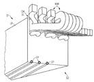
図1は、本発明による冷却装置の一部を示している。多数の積層板LPが積み重ねられている。各積層板LPは多数のスロットSLを有している。積重ねにより、スロットSLは多数のチャネルCHを形成しており、これらのチャネルは、ステータコイルの金属巻線MWを支持するために使用されている。 FIG. 1 shows a part of a cooling device according to the invention. A large number of laminated plates LP are stacked. Each laminated plate LP has a number of slots SL. By stacking, the slot SL forms a number of channels CH, which are used to support the metal winding MW of the stator coil.
積み重ねられた積層板LPはステータセグメントの一部である。積み重ねられた積層板LPは、発電機のロータに対して整合した第1の側S1を有している。スロットSLは、この第1の側S1に配置されている。 Stacked laminates LP are part of the stator segment. The stacked laminate LP has a first side S1 aligned with the rotor of the generator. The slot SL is arranged on the first side S1.
少なくとも1つの冷却管CPは、積み重ねられた積層板LPに部分的に一体化されている。部分的に一体化された冷却管CPは、積み重ねられた積層板LPの第2の側S2において積層板LPを貫通している。第2の側S2は第1の側S1とは反対側である。 At least one cooling pipe CP is partially integrated with the stacked laminate plate LP. The partially integrated cooling pipe CP passes through the laminate LP on the second side S2 of the stacked laminate LP. The second side S2 is opposite to the first side S1.
冷却管CPと積み重ねられた積層板LPとの間には、熱伝導化合物(図示せず)が配置されている。従って、積み重ねられた積層板の不規則な面と冷却管との間の熱的境界面の熱伝導率が高められる。構成部材の間の空隙は低減又は排除され、従って冷却が改善される。化合物は、セラミック、金属、カーボン、又は液体であってよい。 A heat conductive compound (not shown) is disposed between the cooling pipe CP and the stacked laminate plate LP. Therefore, the thermal conductivity of the thermal interface between the irregular surface of the stacked laminate and the cooling pipe is increased. Air gaps between components are reduced or eliminated, thus improving cooling. The compound may be ceramic, metal, carbon, or liquid.
図2は、本発明による積層板LPを側面図で示している。 FIG. 2 shows a laminate plate LP according to the invention in a side view.
積層板LPの第1の側S1は、空隙に整合させられている又は面しており、空隙は発電機のステータとロータとの間に設けられている。第1の側S1は、多数のスロットSLを有している。スロットSLは、金属のシートから打ち抜かれていてよい。積層板LPは、同様に製造されていてよい。 The first side S1 of the laminate LP is aligned with or faces the air gap, which is provided between the stator and the rotor of the generator. The first side S1 has a number of slots SL. The slot SL may be punched from a metal sheet. The laminated plate LP may be manufactured similarly.
図1を参照すると、多数の積み重ねられた積層板LPは、スロットSLによりチャネルCHを形成する。これらのチャネルCHは、ステータコイルの金属巻線MWを支持するために使用されている。 Referring to FIG. 1, a large number of stacked laminate plates LP form a channel CH by slots SL. These channels CH are used to support the metal winding MW of the stator coil.
各金属巻線MWは、導体絶縁体CONIによって包囲された導体CONによって形成されている。各スロットSLは、金属巻線MWの束を絶縁するためのスロット絶縁ライニングSILを有している。 Each metal winding MW is formed by a conductor CON surrounded by a conductor insulator CONI. Each slot SL has a slot insulation lining SIL for insulating the bundle of metal windings MW.
各スロットSLの上部には凹所RCが設けられている。凹所RCは、くさび形部材WDGを支持するように形成されている。電気コイルの金属巻線MWが挿入されると、金属巻線はくさび形部材WDGによって所定の位置に保持される。 A recess RC is provided at the top of each slot SL. The recess RC is formed to support the wedge-shaped member WDG. When the metal winding MW of the electric coil is inserted, the metal winding is held in place by the wedge-shaped member WDG.
多数の冷却管CPは、第1の側S1とは反対側の第2の側S2において、(積み重ねられた)積層板LPに部分的に一体化されている。 The multiple cooling pipes CP are partially integrated with the (stacked) laminated plate LP on the second side S2 opposite to the first side S1.
好適には、冷却管CPの横断面の50%以上が(積み重ねられた)積層板LP内に一体化されている。 Preferably, 50% or more of the cross section of the cooling pipe CP is integrated in the (stacked) laminate LP.
図2は、積み重ねられた積層板を有するステータセグメントの一部だけを示している。積み重ねられた積層板は円形に形成されている。 FIG. 2 shows only a portion of the stator segment with stacked laminates. The stacked laminates are formed in a circular shape.
図3は、図1及び図2に関連した、本発明による装置の一部の三次元の図である。 FIG. 3 is a three-dimensional view of a part of the device according to the invention in relation to FIGS.
図4は、本発明による第1の好適な構成を概略的に示している。 FIG. 4 schematically shows a first preferred configuration according to the invention.
発電機(図示せず)は、例えば熱交換器HXのような共通の冷却手段を有している。 The generator (not shown) has a common cooling means such as a heat exchanger HX.
共通の熱交換器HXは、発電機のセグメント化されたステータの4つのセグメントseg1,seg2,seg3,seg4に接続されている。 The common heat exchanger HX is connected to the four segments seg1, seg2, seg3, seg4 of the segmented stator of the generator.
セグメントseg1〜seg4のそれぞれは、ここに示されているように適切に接続された専用の冷却管の"低温の"入口と"高温の"出口とを有している。従って、ステータセグメントseg1〜seg4と熱交換器HXとの間の長い接続ラインが回避される。 Each of the segments seg1 to seg4 has a “cold” inlet and a “hot” outlet of a dedicated cooling tube appropriately connected as shown here. Accordingly, a long connection line between the stator segments seg1 to seg4 and the heat exchanger HX is avoided.
冷却媒体は、分割されて、4つの冷却経路へ送り込まれ、各冷却経路はセグメントseg1〜seg4のうちの1つのための専用のものである。 The cooling medium is divided and fed into four cooling paths, each cooling path being dedicated for one of the segments seg1 to seg4.
分割された冷却媒体は、専用の冷却経路から出た後に合流される。 The divided cooling media are merged after leaving the dedicated cooling path.
熱交換器HXから見て、冷却管は、並列に接続されていると見なされる。 Viewed from the heat exchanger HX, the cooling tubes are considered to be connected in parallel.
図5は、本発明による第2の好適な構成を概略的に示している。 FIG. 5 schematically shows a second preferred configuration according to the invention.
発電機(図示せず)は、例えば熱交換器HXXのような多数の4つの冷却手段を有している。 The generator (not shown) has a number of four cooling means such as a heat exchanger HXX.
熱交換器HXXは、発電機のセグメント化されたステータの専用のセグメントseg1,seg2,seg3,seg4に接続されている。 The heat exchanger HXX is connected to dedicated segments seg1, seg2, seg3, seg4 of the segmented stator of the generator.
従って、4つの独立した冷却回路が形成されており、各回路は、セグメントseg1〜seg4のうちの1つの冷却管を有している。 Accordingly, four independent cooling circuits are formed, and each circuit has one cooling pipe among the segments seg1 to seg4.
好適には、図1に記載の冷却システムと、図5に記載の冷却システムとは、組み合われてよい。例えば、ステータが8つのセグメントに分割されていると、冷却システムは、2つの冷却手段を有していてよい。冷却手段のそれぞれは、4つのステータセグメントの冷却管から冷却媒体を供給及び受容してよい。 Preferably, the cooling system described in FIG. 1 and the cooling system described in FIG. 5 may be combined. For example, if the stator is divided into eight segments, the cooling system may have two cooling means. Each of the cooling means may supply and receive a cooling medium from the cooling tubes of the four stator segments.
図6及び図7は、本発明による装置において使用される、冷却管CPによって固定された積み重ねられた積層板LPを示している。 6 and 7 show a stacked laminate LP secured by a cooling pipe CP, used in the apparatus according to the invention.
図8Aは、本発明による積層板LPのスロットSLに配置された冷却管CPを概略的に示している。 FIG. 8A schematically shows a cooling pipe CP arranged in a slot SL of a laminate LP according to the present invention.
図8Bは、積層板LPの表面に取り付けられた冷却管CPを概略的に示している。この構成は、従来公知である。 FIG. 8B schematically shows the cooling pipe CP attached to the surface of the laminated plate LP. This configuration is conventionally known.
図8Aによれば、冷却管CPは積層板LPの一体化された部分である。冷却管CPは、長さL1を備えた内部周囲を有している。長さL2は、2つの隣接する冷却管CPの間の距離を表している。図示のように、周囲長さL1は実質的に長さL2と等しい。 According to FIG. 8A, the cooling pipe CP is an integrated part of the laminated plate LP. The cooling pipe CP has an inner periphery with a length L1. The length L2 represents the distance between two adjacent cooling pipes CP. As shown, the perimeter length L1 is substantially equal to the length L2.
図8Bによれば、冷却管CPは、積層板LPの一体化された部分ではなく、実質的にステータの内面における熱伝導板HTに配置されている。熱伝導板HTの最大幅はL2の距離と等しい。 According to FIG. 8B, the cooling pipe CP is not an integrated part of the laminated plate LP, but is disposed on the heat conducting plate HT substantially on the inner surface of the stator. The maximum width of the heat conducting plate HT is equal to the distance L2.
図8Aの例は、図8Bの例と比較して、改良された冷却効率を有する。 The example of FIG. 8A has improved cooling efficiency compared to the example of FIG. 8B.
LP 積層板、 SL スロット、 CH チャネル、 MW 金属巻線、 S1 第1の側、 S2 第2の側、 CP 冷却管、 CONI 導体絶縁体、 CON 導体、 WDG くさび形部材、 RC 凹所、 HX,HXX 熱交換器、 seg1,seg2,seg3,seg4 セグメント、 L1,L2 長さ LP laminate, SL slot, CH channel, MW metal winding, S1 first side, S2 second side, CP cooling tube, CONI conductor insulator, CON conductor, WDG wedge-shaped member, RC recess, HX, HXX heat exchanger, seg1, seg2, seg3, seg4 segment, L1, L2 length
Claims (16)
発電機が、少なくとも2つのステータセグメントを含むステータと、ロータとを有しており、
ステータセグメントのうちの少なくとも1つが、多数の積み重ねられた積層板(LP)を有しており、
該積み重ねられた積層板(LP)が、第1の側(S1)において多数のスロットを有しており、積み重ねられた積層板の第1の側(S1)が、ロータに整合させられており、
スロット(SL)が、ステータコイルの金属巻線(MW)を支持している形式のものにおいて、
少なくとも1つの中空の冷却管(CP)が、該冷却管内に配置された冷却媒体によって積層板(LP)を冷却するために、ステータセグメントの積み重ねられた積層板(LP)に部分的に一体化されていることを特徴とする、風車内で使用される発電機の冷却のための装置。 A device for cooling a generator used in a windmill,
The generator has a stator including at least two stator segments and a rotor;
At least one of the stator segments has a number of stacked laminates (LP);
The stacked laminate (LP) has a number of slots on the first side (S1), and the first side (S1) of the stacked laminate is aligned with the rotor. ,
In the type in which the slot (SL) supports the metal winding (MW) of the stator coil,
At least one hollow cooling tube (CP) is partially integrated into the stacked laminate (LP) of the stator segments for cooling the laminate (LP) by a cooling medium disposed in the cooling tube. A device for cooling a generator used in a wind turbine, characterized in that
冷却媒体が、第1の温度で入口接続部を介して冷却管(CP)に進入し、冷却媒体が、第1の温度よりも高い第2の温度で出口接続部から流出する、請求項1から3までのいずれか1項記載の装置。 The cooling pipe (CP) has an inlet connection and an outlet connection for the cooling medium;
The cooling medium enters the cooling pipe (CP) via the inlet connection at a first temperature, and the cooling medium flows out of the outlet connection at a second temperature that is higher than the first temperature. 4. The apparatus according to any one of items 3 to 3.
発電機が、風車の直接駆動発電機として使用されている、請求項1記載の装置。 The device according to claim 1, wherein the generator has an outer rotor and an inner stator, or the generator is used as a direct drive generator for a wind turbine.
Applications Claiming Priority (1)
| Application Number | Priority Date | Filing Date | Title |
|---|---|---|---|
| EP09013958A EP2320080A1 (en) | 2009-11-06 | 2009-11-06 | Arrangement for cooling of an electrical generator |
Publications (2)
| Publication Number | Publication Date |
|---|---|
| JP2011099442A true JP2011099442A (en) | 2011-05-19 |
| JP2011099442A5 JP2011099442A5 (en) | 2013-11-07 |
Family
ID=42115866
Family Applications (1)
| Application Number | Title | Priority Date | Filing Date |
|---|---|---|---|
| JP2010248891A Pending JP2011099442A (en) | 2009-11-06 | 2010-11-05 | Device for cooling generator |
Country Status (6)
| Country | Link |
|---|---|
| US (1) | US9698653B2 (en) |
| EP (1) | EP2320080A1 (en) |
| JP (1) | JP2011099442A (en) |
| CN (1) | CN102055256A (en) |
| CA (1) | CA2720052A1 (en) |
| NZ (1) | NZ588950A (en) |
Cited By (4)
| Publication number | Priority date | Publication date | Assignee | Title |
|---|---|---|---|---|
| WO2013031982A1 (en) * | 2011-09-02 | 2013-03-07 | 株式会社 東芝 | Water-cooled wind power generation device, and generator cooling method for wind power generation device |
| WO2015037069A1 (en) * | 2013-09-11 | 2015-03-19 | 株式会社日立製作所 | Dynamo-electric machine |
| JP2018516526A (en) * | 2015-06-11 | 2018-06-21 | ヴォッベン プロパティーズ ゲーエムベーハーWobben Properties Gmbh | STATOR RING FOR GENERATOR, GENERATOR AND WIND POWER GENERATOR HAVING THE GENERATOR |
| JP7339678B2 (en) | 2018-03-20 | 2023-09-06 | ラッペーンランナン-ラハデン テクニッリネン ユリオピスト ルト | Electromechanical stators and electromechanical |
Families Citing this family (50)
| Publication number | Priority date | Publication date | Assignee | Title |
|---|---|---|---|---|
| MX2012011571A (en) | 2010-05-04 | 2013-02-12 | Remy Technologies Llc | Electric machine cooling system and method. |
| US9054565B2 (en) | 2010-06-04 | 2015-06-09 | Remy Technologies, Llc | Electric machine cooling system and method |
| EP2580846B1 (en) | 2010-06-08 | 2018-07-18 | Remy Technologies, LLC | Electric machine cooling system and method |
| US8519581B2 (en) | 2010-06-08 | 2013-08-27 | Remy Technologies, Llc | Electric machine cooling system and method |
| US8456046B2 (en) | 2010-06-08 | 2013-06-04 | Remy Technologies, Llc | Gravity fed oil cooling for an electric machine |
| EP2395629A1 (en) | 2010-06-11 | 2011-12-14 | Siemens Aktiengesellschaft | Stator element |
| US8614538B2 (en) | 2010-06-14 | 2013-12-24 | Remy Technologies, Llc | Electric machine cooling system and method |
| US8482169B2 (en) | 2010-06-14 | 2013-07-09 | Remy Technologies, Llc | Electric machine cooling system and method |
| US9281731B2 (en) | 2010-09-23 | 2016-03-08 | Northem Power Systems, Inc. | Method for maintaining a machine having a rotor and a stator |
| US8816546B2 (en) | 2010-09-23 | 2014-08-26 | Northern Power Systems, Inc. | Electromagnetic rotary machines having modular active-coil portions and modules for such machines |
| US8912704B2 (en) | 2010-09-23 | 2014-12-16 | Northern Power Systems, Inc. | Sectionalized electromechanical machines having low torque ripple and low cogging torque characteristics |
| US9359994B2 (en) | 2010-09-23 | 2016-06-07 | Northern Power Systems, Inc. | Module-handling tool for installing/removing modules into/from an electromagnetic rotary machine having a modularized active portion |
| US8789274B2 (en) | 2010-09-23 | 2014-07-29 | Northern Power Systems, Inc. | Method and system for servicing a horizontal-axis wind power unit |
| US8446056B2 (en) | 2010-09-29 | 2013-05-21 | Remy Technologies, Llc | Electric machine cooling system and method |
| US8492952B2 (en) | 2010-10-04 | 2013-07-23 | Remy Technologies, Llc | Coolant channels for electric machine stator |
| US8508085B2 (en) | 2010-10-04 | 2013-08-13 | Remy Technologies, Llc | Internal cooling of stator assembly in an electric machine |
| US8395287B2 (en) | 2010-10-04 | 2013-03-12 | Remy Technologies, Llc | Coolant channels for electric machine stator |
| US8593021B2 (en) | 2010-10-04 | 2013-11-26 | Remy Technologies, Llc | Coolant drainage system and method for electric machines |
| EP2451048A1 (en) * | 2010-11-04 | 2012-05-09 | Siemens Aktiengesellschaft | Magnetic cap element for closing a cooling channel in a stator of a generator |
| US8648506B2 (en) | 2010-11-09 | 2014-02-11 | Remy Technologies, Llc | Rotor lamination cooling system and method |
| US8497608B2 (en) | 2011-01-28 | 2013-07-30 | Remy Technologies, Llc | Electric machine cooling system and method |
| WO2012145302A2 (en) | 2011-04-18 | 2012-10-26 | Remy Technologies, Llc | Electric machine module cooling system and method |
| US8692425B2 (en) | 2011-05-10 | 2014-04-08 | Remy Technologies, Llc | Cooling combinations for electric machines |
| DE202011050160U1 (en) * | 2011-05-17 | 2011-07-20 | Lloyd Dynamowerke Gmbh & Co. Kg | Stator and generator with a stator |
| US8803380B2 (en) | 2011-06-03 | 2014-08-12 | Remy Technologies, Llc | Electric machine module cooling system and method |
| US20120318479A1 (en) * | 2011-06-14 | 2012-12-20 | Fukuta Electric & Machinery Co., Ltd. | Liquid cooled motor assembly and cover thereof |
| US9041260B2 (en) | 2011-07-08 | 2015-05-26 | Remy Technologies, Llc | Cooling system and method for an electronic machine |
| US8803381B2 (en) | 2011-07-11 | 2014-08-12 | Remy Technologies, Llc | Electric machine with cooling pipe coiled around stator assembly |
| US8546982B2 (en) | 2011-07-12 | 2013-10-01 | Remy Technologies, Llc | Electric machine module cooling system and method |
| US9048710B2 (en) | 2011-08-29 | 2015-06-02 | Remy Technologies, Llc | Electric machine module cooling system and method |
| DE102011082353B4 (en) * | 2011-09-08 | 2021-04-01 | Siemens Aktiengesellschaft | Stator for an electric motor |
| US8975792B2 (en) | 2011-09-13 | 2015-03-10 | Remy Technologies, Llc | Electric machine module cooling system and method |
| US9099900B2 (en) | 2011-12-06 | 2015-08-04 | Remy Technologies, Llc | Electric machine module cooling system and method |
| US9331543B2 (en) | 2012-04-05 | 2016-05-03 | Remy Technologies, Llc | Electric machine module cooling system and method |
| DK201270179A (en) * | 2012-04-11 | 2013-10-11 | Envision Energy Denmark Aps | Wind turbine with improved cooling |
| US10069375B2 (en) | 2012-05-02 | 2018-09-04 | Borgwarner Inc. | Electric machine module cooling system and method |
| ITMI20121304A1 (en) * | 2012-07-25 | 2014-01-26 | Wilic Sarl | ROTOR OF A ROTATING ELECTRIC MACHINE FOR GAS MILLER AND AIRCONDITIONER INCLUDING SUCH ROTOR |
| ITMI20121301A1 (en) * | 2012-07-25 | 2014-01-26 | Wilic Sarl | ACTIVE SEGMENT OF A ROTARY ELECTRIC MACHINE FOR THE AIRCONDITIONER, ROTARY ELECTRIC MACHINE, AND VENTILATOR |
| US20140262155A1 (en) * | 2013-03-14 | 2014-09-18 | Lincoln Global, Inc. | Orbital welding system with cooled drive housing |
| ITMI20131548A1 (en) | 2013-09-19 | 2015-03-20 | Wilic Sarl | STATOR OF A ROTATING ELECTRIC MACHINE OF A AIRCRAFT MACHINE |
| US10804755B2 (en) * | 2017-07-25 | 2020-10-13 | Toshiba International Corporation | Stator core with at least three cooling pipes with end crimps |
| CN107332373A (en) * | 2017-08-22 | 2017-11-07 | 彭希南 | Permanent magnetic brushless stator and rotor structure of a kind of high pulling torque with cooling water pipe |
| US10756598B2 (en) | 2017-10-02 | 2020-08-25 | Ge Aviation Systems Llc | Method and apparatus for cooling a rotor assembly |
| CN111697766A (en) * | 2019-03-14 | 2020-09-22 | 南京德朔实业有限公司 | Electric tool and motor thereof |
| AT523102A1 (en) * | 2019-10-31 | 2021-05-15 | B & R Ind Automation Gmbh | Transport device in the form of a long stator linear motor |
| AT523101A1 (en) * | 2019-10-31 | 2021-05-15 | B & R Ind Automation Gmbh | Transport device in the form of a long stator linear motor |
| CN111817457A (en) * | 2020-07-03 | 2020-10-23 | 浙江实日机电科技有限公司 | Stator core of automobile starting motor and processing technology thereof |
| US20220003128A1 (en) * | 2020-07-06 | 2022-01-06 | General Electric Company | Dual rotor electric machine |
| US11719122B2 (en) | 2021-02-08 | 2023-08-08 | General Electric Company | Gas turbine engines including embedded electrical machines and associated cooling systems |
| CN113370195B (en) * | 2021-06-30 | 2022-09-09 | 哈尔滨科能熔敷科技股份有限公司 | Mechanical arm applied to high-temperature working condition |
Citations (5)
| Publication number | Priority date | Publication date | Assignee | Title |
|---|---|---|---|---|
| JPS5351407A (en) * | 1976-10-21 | 1978-05-10 | Toshiba Corp | Revolving electrical machinery |
| JP2001119872A (en) * | 1999-10-15 | 2001-04-27 | Mitsubishi Electric Corp | Synchronous rotating electric machine, wind turbine power generator, and manufacturing methods for them |
| JP2003510492A (en) * | 1999-09-24 | 2003-03-18 | ラヘルウェイ・ウィントトゥルビネ・ベスローテン・フェンノートシャップ | Wind generator |
| JP2004180498A (en) * | 2002-11-26 | 2004-06-24 | General Motors Corp <Gm> | Concentrated volume coil electric motor with optimized coil cooling and slot filling |
| JP2009213353A (en) * | 2002-07-18 | 2009-09-17 | Tm4 Inc | Liquid cooling arrangement for stator of electrical machine |
Family Cites Families (23)
| Publication number | Priority date | Publication date | Assignee | Title |
|---|---|---|---|---|
| US3681628A (en) * | 1970-09-14 | 1972-08-01 | Christoslaw Krastchew | Cooling arrangement for a dynamoelectric machine |
| US3704078A (en) * | 1971-01-22 | 1972-11-28 | Hydr O Matic Pump Co | Deep well type pump |
| US5473207A (en) * | 1993-11-04 | 1995-12-05 | General Electric Co. | Cooling pads for water-cooled stator cores in dynamoelectric machines and methods of fabrication |
| US5408152A (en) * | 1994-03-28 | 1995-04-18 | Westinghouse Electric Corporation | Method of improving heat transfer in stator coil cooling tubes |
| DE19604643B4 (en) * | 1996-02-08 | 2004-04-15 | Siemens Ag | Linear motor with integrated cooling |
| AU3052897A (en) * | 1996-05-29 | 1998-01-05 | Asea Brown Boveri Ab | Axial cooling tubes provided with clamping means |
| SE9703557D0 (en) * | 1997-09-30 | 1997-09-30 | Asea Brown Boveri | Method of applying a cooling tube to a cooling tube duct |
| JPH11307430A (en) * | 1998-04-23 | 1999-11-05 | Canon Inc | Aligner, manufacture of device, and drive |
| NL1011876C2 (en) * | 1999-04-23 | 2000-10-24 | Aerpac Holding B V | Generator. |
| JP4111418B2 (en) | 2001-02-28 | 2008-07-02 | ペンタックス株式会社 | Calcium phosphate cement for living bone reinforcement treatment capable of forming a high-strength hardened body |
| US6330809B1 (en) * | 2000-12-08 | 2001-12-18 | General Electric Company | Application of a chiller in an apparatus for cooling a generator/motor |
| DE10103447A1 (en) * | 2001-01-25 | 2002-08-01 | Baumueller Nuernberg Gmbh | Corrugated tube stator cooling in an electrical machine |
| DE10115186A1 (en) * | 2001-03-27 | 2002-10-24 | Rexroth Indramat Gmbh | Cooled primary or secondary part of an electric motor |
| ES2319392T3 (en) * | 2001-04-20 | 2009-05-07 | Converteam Ltd | REFRIGERATION OF A WINDING ENTREHIERRO OF ELECTRICAL MACHINES. |
| US7193342B2 (en) * | 2002-12-17 | 2007-03-20 | Caterpillar Inc | Apparatus for cooling of electrical devices |
| DE102004052070A1 (en) | 2004-10-26 | 2006-05-18 | Siemens Ag | Electric machine |
| US7443066B2 (en) * | 2005-07-29 | 2008-10-28 | General Electric Company | Methods and apparatus for cooling wind turbine generators |
| US7545060B2 (en) * | 2006-03-14 | 2009-06-09 | Gm Global Technology Operations, Inc. | Method and apparatus for heat removal from electric motor winding end-turns |
| US7592721B2 (en) | 2006-09-20 | 2009-09-22 | American Superconductor Corporation | Torque transmission assembly for superconducting rotating machines |
| ES2431593T3 (en) | 2008-04-10 | 2013-11-27 | Siemens Aktiengesellschaft | Stator, generator and wind turbine layout |
| FI120782B (en) | 2008-04-18 | 2010-02-26 | Abb Oy | Heat sink for electric machine |
| EP2182612A1 (en) | 2008-10-28 | 2010-05-05 | Siemens Aktiengesellschaft | Arrangement for cooling of an electrical machine |
| EP2320540A1 (en) | 2009-11-05 | 2011-05-11 | Siemens Aktiengesellschaft | Arrangement for cooling of an electrical machine |
-
2009
- 2009-11-06 EP EP09013958A patent/EP2320080A1/en not_active Withdrawn
-
2010
- 2010-10-14 US US12/904,338 patent/US9698653B2/en not_active Expired - Fee Related
- 2010-11-01 NZ NZ588950A patent/NZ588950A/en not_active IP Right Cessation
- 2010-11-04 CA CA2720052A patent/CA2720052A1/en not_active Abandoned
- 2010-11-05 CN CN2010105413055A patent/CN102055256A/en active Pending
- 2010-11-05 JP JP2010248891A patent/JP2011099442A/en active Pending
Patent Citations (5)
| Publication number | Priority date | Publication date | Assignee | Title |
|---|---|---|---|---|
| JPS5351407A (en) * | 1976-10-21 | 1978-05-10 | Toshiba Corp | Revolving electrical machinery |
| JP2003510492A (en) * | 1999-09-24 | 2003-03-18 | ラヘルウェイ・ウィントトゥルビネ・ベスローテン・フェンノートシャップ | Wind generator |
| JP2001119872A (en) * | 1999-10-15 | 2001-04-27 | Mitsubishi Electric Corp | Synchronous rotating electric machine, wind turbine power generator, and manufacturing methods for them |
| JP2009213353A (en) * | 2002-07-18 | 2009-09-17 | Tm4 Inc | Liquid cooling arrangement for stator of electrical machine |
| JP2004180498A (en) * | 2002-11-26 | 2004-06-24 | General Motors Corp <Gm> | Concentrated volume coil electric motor with optimized coil cooling and slot filling |
Cited By (5)
| Publication number | Priority date | Publication date | Assignee | Title |
|---|---|---|---|---|
| WO2013031982A1 (en) * | 2011-09-02 | 2013-03-07 | 株式会社 東芝 | Water-cooled wind power generation device, and generator cooling method for wind power generation device |
| JP2013053548A (en) * | 2011-09-02 | 2013-03-21 | Toshiba Corp | Water-cooled wind power generation device, and generator cooling method for wind power generation device |
| WO2015037069A1 (en) * | 2013-09-11 | 2015-03-19 | 株式会社日立製作所 | Dynamo-electric machine |
| JP2018516526A (en) * | 2015-06-11 | 2018-06-21 | ヴォッベン プロパティーズ ゲーエムベーハーWobben Properties Gmbh | STATOR RING FOR GENERATOR, GENERATOR AND WIND POWER GENERATOR HAVING THE GENERATOR |
| JP7339678B2 (en) | 2018-03-20 | 2023-09-06 | ラッペーンランナン-ラハデン テクニッリネン ユリオピスト ルト | Electromechanical stators and electromechanical |
Also Published As
| Publication number | Publication date |
|---|---|
| US9698653B2 (en) | 2017-07-04 |
| EP2320080A1 (en) | 2011-05-11 |
| NZ588950A (en) | 2012-05-25 |
| CA2720052A1 (en) | 2011-05-06 |
| CN102055256A (en) | 2011-05-11 |
| US20110109095A1 (en) | 2011-05-12 |
Similar Documents
| Publication | Publication Date | Title |
|---|---|---|
| JP2011099442A (en) | Device for cooling generator | |
| JP2010110205A (en) | Arrangement for cooling electrical machine | |
| EP2518868B1 (en) | Cooling arrangement for an electric machine | |
| FI124814B (en) | Electric machine stator and electric machine | |
| JP5038596B2 (en) | AC winding with integrated cooling system and method of manufacturing the same | |
| KR101365641B1 (en) | Arrangement and method for cooling an electrical machine | |
| US20100102650A1 (en) | Arrangement for cooling of an electrical machine | |
| JP2009284755A (en) | Cooling element for electric machine | |
| US8040000B2 (en) | Stator cooling structure for superconducting rotating machine | |
| US20130270937A1 (en) | Wind turbine with improved cooling | |
| JP2010110202A (en) | Arrangement for cooling electrical machine | |
| CN109494901A (en) | A kind of trough inner water cool electric machine stator | |
| DK2313959T3 (en) | Rotor for a multi-pole synchronous electric motor with protruding poles | |
| US20120091723A1 (en) | Generator, in particular for a wind turbine | |
| CN102842407A (en) | Cooling device for electrical device and method of cooling an electrical device | |
| KR101055009B1 (en) | Generator and electric motor | |
| KR101243291B1 (en) | Apparatus of air cooling for stator coils of superconduting motor or generator | |
| CN116094199B (en) | Multiplexing type modularized permanent magnet wind driven generator stator structure | |
| JPS58170337A (en) | Cooler for stator core part of rotary electric machine | |
| KR101056400B1 (en) | Rotor core for rotary electric machine | |
| US20120091722A1 (en) | Generator in particular for a wind turbine | |
| WO2024049403A1 (en) | Cooling system for a superconducting generator | |
| CN116896197A (en) | Power device and wind driven generator comprising same | |
| JP2004120823A (en) | Core-less linear motor and cooling system therefor | |
| KR20090110794A (en) | Cooling element for an electrical machine |
Legal Events
| Date | Code | Title | Description |
|---|---|---|---|
| A521 | Request for written amendment filed |
Free format text: JAPANESE INTERMEDIATE CODE: A523 Effective date: 20130919 |
|
| A621 | Written request for application examination |
Free format text: JAPANESE INTERMEDIATE CODE: A621 Effective date: 20130919 |
|
| A977 | Report on retrieval |
Free format text: JAPANESE INTERMEDIATE CODE: A971007 Effective date: 20140828 |
|
| A131 | Notification of reasons for refusal |
Free format text: JAPANESE INTERMEDIATE CODE: A131 Effective date: 20140901 |
|
| A02 | Decision of refusal |
Free format text: JAPANESE INTERMEDIATE CODE: A02 Effective date: 20150302 |