JP2011095627A - Lens unit, led head, exposure device, image forming apparatus, and reading apparatus - Google Patents
Lens unit, led head, exposure device, image forming apparatus, and reading apparatus Download PDFInfo
- Publication number
- JP2011095627A JP2011095627A JP2009251370A JP2009251370A JP2011095627A JP 2011095627 A JP2011095627 A JP 2011095627A JP 2009251370 A JP2009251370 A JP 2009251370A JP 2009251370 A JP2009251370 A JP 2009251370A JP 2011095627 A JP2011095627 A JP 2011095627A
- Authority
- JP
- Japan
- Prior art keywords
- lens
- distance
- plane
- lens unit
- optical axis
- Prior art date
- Legal status (The legal status is an assumption and is not a legal conclusion. Google has not performed a legal analysis and makes no representation as to the accuracy of the status listed.)
- Pending
Links
Images


Classifications
-
- G—PHYSICS
- G02—OPTICS
- G02B—OPTICAL ELEMENTS, SYSTEMS OR APPARATUS
- G02B3/00—Simple or compound lenses
- G02B3/0006—Arrays
Abstract
Description
本発明は、レンズユニット、LEDヘッド、露光装置、画像形成装置および読取装置に関する。 The present invention relates to a lens unit, an LED head, an exposure apparatus, an image forming apparatus, and a reading apparatus.
従来のレンズユニットは、複数のLED(発光ダイオード)を直線状に配列したLEDヘッドを用いた電子写真方式の画像形成装置や、複数の受光素子を直線状に配列した受光部に読取り原稿の像を結像させるスキャナやファクシミリ等の読取装置の結像面に物体の正立等倍像をライン状に形成することができる光学系として用いられている。 Conventional lens units include an electrophotographic image forming apparatus using an LED head in which a plurality of LEDs (light emitting diodes) are linearly arranged, and an image of a document read on a light receiving portion in which a plurality of light receiving elements are linearly arranged. Is used as an optical system capable of forming an erecting equal-magnification image of an object in a line shape on an image formation surface of a reading device such as a scanner or a facsimile.
このレンズユニットを、物体の縮小倒立像を形成するレンズと、拡大倒立像を形成するレンズとを対向させて配置したレンズ対として構成し、複数の該レンズ対を略直線状に配列して物体の正立等倍像をライン状に形成する光学系として構成するようにしているものがある(例えば、特許文献1参照)。 This lens unit is configured as a lens pair in which a lens that forms a reduced inverted image of an object and a lens that forms an enlarged inverted image are opposed to each other, and a plurality of the lens pairs are arranged in a substantially straight line. Is configured as an optical system that forms an erecting equal-magnification image in a line shape (see, for example, Patent Document 1).
しかしながら、上述した従来の技術においては、レンズ対と結像面の間隔が変化すると結像が分裂して形成されるため、焦点深度を深くすることができないという問題がある。 However, in the above-described conventional technology, there is a problem in that the depth of focus cannot be increased because the image formation is split when the distance between the lens pair and the image formation surface changes.
本発明は、このような問題を解決することを課題とし、焦点深度が深い光学系を提供することを目的とする。 An object of the present invention is to solve such a problem, and an object thereof is to provide an optical system having a deep focal depth.
そのため、本発明による光学系は、物体の倒立像を中間像面上に中間像として形成する第1のレンズと該第1のレンズが形成した中間像の倒立像を結像面上に形成する第2のレンズとからなるレンズ対が、該レンズ対の光軸と直交する方向へ略直線に複数配列されたレンズアレイを有するレンズユニットにおいて、前記第1のレンズの第1主平面と物体面との距離をSO1、前記第1のレンズの第2主平面と前記中間像面との距離をSI1、前記第2のレンズの第1主平面と前記中間像面との距離をSO2、前記第2のレンズの第2主平面と前記結像面との距離をSI2としたとき、距離SO1の距離SI1に対する比が、距離SI2の距離SO2に対する比に略等しく、前記第1のレンズと前記物体面との間隔が、前記第2のレンズと前記結像面との間隔と異なるように形成されていることを特徴とする。
For this reason, the optical system according to the present invention forms, on the imaging surface, a first lens that forms an inverted image of an object as an intermediate image on the intermediate image plane and an inverted image of the intermediate image formed by the first lens. In a lens unit having a lens array in which a plurality of lens pairs each including a second lens are arranged in a substantially straight line in a direction orthogonal to the optical axis of the lens pair, the first main plane and the object plane of the first lens The distance between the second main plane of the first lens and the intermediate image plane is SI1, the distance between the first main plane of the second lens and the intermediate image plane is SO2, and the first When the distance between the second principal plane of the
このようにした本発明は、焦点深度の深い光学系を構成することができるという効果が得られる。 The effect of the present invention as described above is that an optical system having a deep depth of focus can be configured.
以下、図面を参照して本発明によるレンズユニット、LEDヘッド、露光装置、画像形成装置および読取装置の実施例を説明する。 Hereinafter, embodiments of a lens unit, an LED head, an exposure apparatus, an image forming apparatus, and a reading apparatus according to the present invention will be described with reference to the drawings.
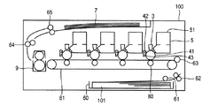
本実施例の画像形成装置としてのプリンタを図2の第1の実施例におけるプリンタの構成を示す概略図に基づいて説明する。 A printer as an image forming apparatus according to this embodiment will be described with reference to a schematic diagram illustrating a configuration of the printer according to the first embodiment shown in FIG.
図2において、プリンタ100は、色材としての顔料を含む樹脂からなるトナーにより、画像データをもとに印字媒体上に画像を形成する。
In FIG. 2, a
プリンタ100には、印字媒体としての用紙101を貯留する給紙カセット60が装着され、用紙101を給紙カセット60から取り出す給紙ローラ61を備え、用紙101を給紙して搬送する搬送ローラ62、63が配置される。
The
本発明におけるプリンタ100は、カラー電子写真方式であり、プリンタ100内には画像形成部としてイエロー、マゼンダ、シアン、ブラックの各色の画像を形成する静電潜像担持体としての感光体ドラム41、その感光体ドラム41に形成された静電潜像をトナーにより現像し、トナー像を形成する現像器5、その現像器5にトナーを供給するトナーカートリッジ51が用紙101の搬送路に沿って並べて配置されている。
The
また、感光体ドラム41の表面に電荷を供給して帯電させる帯電ローラ42、光学ヘッドとしてのLEDヘッド3が、感光体ドラム41の表面に対向するように配置され、LEDヘッド3は帯電ローラ42で帯電された感光体ドラム41の表面に画像データをもとに選択的に光を照射して静電画像を形成する。
Further, a
さらに、感光体ドラム41上に形成され、トナーにより静電潜像を可視化した像であるトナー像を用紙101上に転写する転写ローラ80が、転写部で用紙101を搬送する転写ベルト81を挟むように感光体ドラム41に対向して配置され、また用紙101が転写部を通過した後の感光体ドラム41の表面に残留したトナーを除去するクリーニングブレード43が感光体ドラム41の表面に接触して配置されている。
Further, a
転写部の下流には用紙101上に形成されたトナー像を熱および圧力で定着させる定着器9が配置され、その定着器9を通過した用紙101を搬送する搬送ローラ64、その搬送ローラ64により搬送され、画像が形成された用紙101を貯留する排出部7へ排出する排出ローラ65が配置される。
A fixing device 9 for fixing the toner image formed on the
また、帯電ローラ42および転写ローラ80には図示しない電源により所定の電圧が印加される。そして、転写ベルト81、感光体ドラム41および各ローラはそれぞれ図示しないモータと図示しない駆動を伝達するギアにより回転駆動される。さらに、現像器5、LEDヘッド3、定着器9、および図示しない各モータには、それぞれ電源および制御装置が接続されている。
A predetermined voltage is applied to the
プリンタ100は、外部装置から印刷データを受信する外部インターフェースを有し、その外部インターフェースで受信した印刷データをもとに印字媒体上に画像を形成する。
The
このように構成されたプリンタ100は、制御プログラムをメモリ等の記憶部に記憶し、その制御プログラムに基づいて全体を制御する制御手段および演算手段としての制御部を備えている。
The
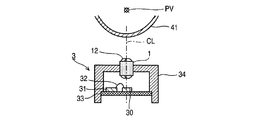
次に、露光装置としてのLEDヘッド3の構成を図3の第1の実施例におけるLEDヘッドの概略説明図に基づいて説明する。
Next, the configuration of the
LEDヘッド3には、レンズユニット1が配置され、そのレンズユニット1はホルダ34によりLEDヘッド3に固定されている。また、発光部としての複数のLED素子30は図面の水平方向に略直線に配置されている。
A
41は静電潜像が形成される感光体ドラム、PVは感光体ドラム41の回転軸であり、感光体ドラム41は図面の水平方向が回転軸PVとなるように配置されている。
レンズユニット1は、長尺であり、略直線に配置されたLED素子30と平行に配置され、またレンズユニット1と感光体ドラム41の回転軸PVは平行に配置される。さらに、レンズユニット1に配列される各マイクロレンズの光軸は図面の鉛直方向になるように配置される。
The
図4は、第1の実施例におけるLEDヘッドの概略断面図であり、図3におけるAA断面図である。 FIG. 4 is a schematic cross-sectional view of the LED head in the first embodiment, and is a cross-sectional view taken along AA in FIG.
図4において、レンズユニット1の各マイクロレンズ12の光軸は図5におけるz方向、レンズユニット1の中心線CLがLED素子30と感光体ドラム41表面を結ぶ線と一致するように配置され、またLED素子30は間隔PDを保持して図5におけるy方向に複数配列されている。さらに、感光体ドラム41は回転軸PVが図5におけるy方向になるように配置されている。
4, the optical axis of each
LED素子30およびドライバIC31は配線基板33上に配置されている。LED素子30とドライバIC31はワイヤ32により結線され、発光部としてのLED素子30はドライバIC31により制御されて発光する。
The
このレンズユニット1により、感光体ドラム41にLED素子30の像が結像し、感光体ドラム41の回転に合わせてLED素子30を発光させることにより感光体ドラム41上に静電潜像が形成される。
With this
本実施例においては、LEDヘッド3は600dpi(dots per inch)の解像度であり、LED素子30が1インチ当たり(1インチは約25.4mm)600個配置されている。すなわち、LED素子30が、間隔PDを0.0423mmとして配列されている。
In this embodiment, the
次に、レンズユニット1の構成を図5の第1の実施例におけるレンズユニットの分解斜視図に基づいて説明する。
Next, the configuration of the
図5において、レンズユニット1は、レンズ素子の集合体としてのレンズアレイ10と遮光部材としての遮光板20とからなり、2枚のレンズアレイ10が遮光板20を挟んで対向して配置されている。
In FIG. 5, the
そのレンズアレイ10には、複数のレンズ素子としてのマイクロレンズ12がy方向に略直線状に配列されている。また、遮光板20には、絞りとしての略半円形状の開口部22がy方向に略直線状に複数配列され、LED素子30からの発光光線がレンズアレイ10のマイクロレンズ12の配置に対応するように貫通孔として形成された各開口部22を通して透過する。
In the
マイクロレンズ12と開口部22の配列方向はy方向であり、互いに平行し、またマイクロレンズ12と開口部22の光線の透過方向はz方向で略同一方向である。
The arrangement direction of the
図6は第1の実施例におけるレンズユニットの断面図であり、図3のAAの位置におけるマイクロレンズ12の配列方向(図5におけるy方向)と直交する平面による断面図である。 6 is a cross-sectional view of the lens unit in the first embodiment, and is a cross-sectional view taken along a plane orthogonal to the arrangement direction of the microlenses 12 (y direction in FIG. 5) at the position AA in FIG.
図6において、AXは、図面における右側の列のマイクロレンズ12の光軸であり、図面の鉛直方向(図5におけるz方向)に配置されている。また、マイクロレンズ12の配列方向は図面と直交する方向(図5におけるy方向)となるように配列されている。
In FIG. 6, AX is the optical axis of the
CLは、マイクロレンズ12の配列方向(図5におけるy方向)と光軸AX(図5におけるz方向)の両方に直交する方向(レンズアレイ幅方向:図5におけるx方向)におけるレンズユニット1の中央(マイクロレンズ12の2つ配列の中心位置)を示す中心線である。
CL denotes the
レンズユニット1は、2枚のレンズアレイ10の各マイクロレンズ12の光軸AXが一致し、さらに遮光板20の開口部22の位置が光軸AXに一致している。すなわち、レンズユニット1は、光軸AXが一致するように配置された2枚のマイクロレンズ12からなるレンズ対を光軸AXに対して直交する方向(図5におけるy方向)に2列に配列した構成となっている。
In the
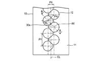
図7は、第1の実施例におけるレンズアレイの平面図である。図7におけるレンズアレイ10は、レンズユニット1の物体側を示している。
FIG. 7 is a plan view of the lens array in the first embodiment. A
図7において、レンズアレイ10には、複数のマイクロレンズ12が、平行する2列の略直線に交互に配置され、各列で並ぶそれぞれのマイクロレンズ12の間隔はPY、二つの平行する列、すなわちマイクロレンズ12の配列方向と光軸AXの両方に直交する方向(図5におけるx方向)の間隔はPXである。
In FIG. 7, in the
2列のマイクロレンズ12の各列と図示しない複数のLED素子30が配置された直線は互いに平行であり、また2列のマイクロレンズ12の各列と図示しない複数のLED素子30が配置された直線との距離は等しくなるように構成されている。
The straight lines on which the two rows of
列間で隣接するマイクロレンズ12の中心間を間隔PNとすると、間隔PN<間隔PYとなっており、2つの列間で隣接するマイクロレンズ12は互いにオーバーラップするようにマイクロレンズ12の表面が途中で連結されて配置されている。また、マイクロレンズ12は、半径RLの円と半径RLの円の中心から間隔PN/2を隔てた位置にある直線とからなる形状となっている。
Assuming that the interval between the centers of the
ここで、レンズアレイ10を結像面側に配置する場合の構成を説明する。この場合、レンズアレイ10の各部の構成は、物体面側に配置する場合と同様であるが、寸法が異なる。つまり、図7示したマイクロレンズ12の各寸法のうち、半径が異なり、半径RLを半径RL2に置き換えることにより、結像面側に配置されるレンズアレイ10を示すものとする。
Here, a configuration in the case where the
なお、レンズアレイ10は、物体(LED素子30)からの光線を透過する素材により形成されている。
The
本実施例のレンズユニット1では、レンズアレイ10はシクロオレフィン系樹脂である光学樹脂(日本ゼオン社製、商品名;ZEONEX(ゼオネックス)(登録商標)E48R)を使用し、射出成型により複数のマイクロレンズ12を一体に成型した。
In the
マイクロレンズ12の各曲面(マイクロレンズ12と空気層の境界面)は数式1で表される多項式非球面で構成される。Z(r)は、マイクロレンズ12の光軸に平行な方向を軸とし、半径方向の座標をrとした回転座標系を示し、マイクロレンズ12の各曲面の頂点を原点とし、マイクロレンズ12側の方向を正の数で表し、空気層側の方向を負の数で表す。このとき、半径rはX座標、Y座標の値を用いて、数式2で表される。kはコーニック定数、Cは曲率半径、Aは非球面係数、lとmは正の整数である。

図8は、第1の実施例における遮光板の平面図である。
図8において、遮光板20には、間隔PYで略直線に開口部22が形成され、その開口部22は、マイクロレンズ12の光軸AX(図5におけるz方向)と開口部22の配列方向(図5におけるy方向)の両方に直交する方向(図5におけるx方向)に間隔PXで2列に配列されている。
FIG. 8 is a plan view of the light shielding plate in the first embodiment.
In FIG. 8, the
また、開口部22は、隣接するマイクロレンズ12に対応してその中心間を間隔PNとして形成され、間隔PN<間隔PYとなっている。さらに、開口部22は、半径RAの円の中心から距離RAXを隔てた位置にある開口部22の配列方向(図5におけるy方向)と平行な直線と、半径RAの円とからなる形状である。
Further, the
開口部22の半径RAの円の中心は、マイクロレンズ12の光軸AXと一致するように構成されている。
なお、遮光板20は、物体(LED素子30)からの光線を遮光する素材により形成されている。
本実施例の遮光板20は、黒色のポリカーボネートを用いて射出成型により作成した。
The center of the circle having the radius RA of the
The
The
次にレンズユニット1の詳細を図7および図9の第1の実施例におけるレンズアレイの動作を示す説明図に基づいて説明する。図7は、レンズアレイ10の平面図であり、物体(LED素子30)と光軸AXとの位置関係を示す。物体30aは、LED素子30のうち、隣接する2つのマイクロレンズ12の光軸AXの中間にあるものを示している。図9はレンズアレイ10を含むレンズユニット1および物体面OPならびに結像面IPの断面図であり、隣接する2つのマイクロレンズ12の各光軸AXを含む平面による断面図、すなわち図7および図8における直線BBの位置における断面図である。
Next, the details of the
図9において、レンズユニット1の物体面OPから距離LOの位置に第1のレンズアレイ10aが配置され、さらに第2のレンズアレイ10bが第1のレンズアレイ10aと対向して、距離LSを隔てて配置される。レンズユニット1の結像面IPは第2のレンズアレイ10bから光軸AX方向に距離LIを隔てた位置である。
In FIG. 9, the
遮光板20は、第1のレンズアレイ10aと第2のレンズアレイ10bの間に配置される。また、第1のマイクロレンズ12aと第2のマイクロレンズ12bは、それぞれの光軸が光軸AXに一致するように配置される。
The
本実施例においては、距離LOと距離LIとは、異なる値に構成され、距離LIは距離LOより大きくなるように構成されている。 In this embodiment, the distance LO and the distance LI are configured to have different values, and the distance LI is configured to be larger than the distance LO.
第1のマイクロレンズ12aは、厚さがLT1であり、光軸AX方向に距離LO1の位置にある物体30aの像を中間像30bとして、光軸AX方向に距離LI1離れた中間像面IMPに形成する。
The
第2のマイクロレンズ12bは、厚さがLT2であり、距離LO2の位置にある中間像面IMP上の中間像30bの結像30cを、光軸AX方向に距離LI2隔てた位置に形成する。
The
レンズユニット1の物体面OPから第1のマイクロレンズ12aまでの距離LOは距離LO1と等しく設定され、第1のマイクロレンズ12aと第2のマイクロレンズ12bの間隔LSは、(距離LI1+距離LO2)に設定され、第2のマイクロレンズ12bからレンズユニット1の結像面IPまでの距離LIは距離LI2と等しく設定される。
The distance LO from the object plane OP of the
本実施例においては、距離LO1と距離LI2とは異なる値に構成され、結像面IPである感光体ドラム41が回転体であるため、面間隔の変動が発生しやすい距離LI2が距離LO1と比べて大きくなるように構成されている。
In this embodiment, the distance LO1 and the distance LI2 are configured to have different values, and the
このようにレンズユニット1は、遮光板20を挟んで2個のレンズアレイ10が対向して結像面に結像できる間隔で保持されて配置され、正立等倍率の光学系を形成している。このように光軸が一致する2個のマイクロレンズ12からなる光学系は、LED素子30の像を感光体ドラム41の表面に正立等倍率で結像することができる。
As described above, the
また、遮光板20は、レンズアレイ10の間にあって光軸が一致する2個のマイクロレンズからなる光学系に他の光学系から入る迷光(一部の光)を遮断するとともに他の光学系に迷光を出さないように遮断している。
Further, the
上述した構成の作用について説明する。
まず、プリンタ100の動作を図2に基づいて説明する。
The operation of the above configuration will be described.
First, the operation of the
プリンタ100の感光体ドラム41表面は、図示しない電源装置により電圧が印加された帯電ローラ42により帯電される。続いて、感光体ドラム41が回転することによって帯電された感光体ドラム41表面がLEDヘッド3の付近に到達するとLEDヘッド3によって露光され、感光体ドラム41表面に静電潜像が形成される。この静電潜像は現像器5により現像され、感光体ドラム41の表面にトナー像が形成される。
The surface of the
一方、給紙カセット60にセットされた用紙101が給紙ローラ61によって給紙カセット60から取り出され、搬送ローラ62、63により、転写ローラ80および転写ベルト81の付近に搬送される。
On the other hand, the
感光体ドラム41が回転することにより、現像によって得られた感光体ドラム41表面上のトナー像が転写ローラ80および転写ベルト81の付近に到達すると図示しない電源装置により電圧が印加されている転写ローラ80および転写ベルト81によって、感光体ドラム41表面上のトナー像は用紙101上に転写される。
When the
続いて、表面にトナー像が形成された用紙101は、転写ベルト81の回転により定着器9へ搬送され、用紙101上のトナー像はその定着器9により加圧されながら加熱されることにより溶解し、用紙101上に固定される。トナー像が固定された用紙101は、搬送ローラ64および排出ローラ65により排出部7に排出されてプリンタ100の動作が終了する。
Subsequently, the
次に、露光装置としてのLEDヘッド3の動作を図4に基づいて説明する。
画像データをもとにプリンタ100の制御部によりLEDヘッド3の制御信号が発信されるとドライバIC31はその制御信号に基づき任意の光量でLED素子30が発光する。そのLED素子30からの光線はレンズユニット1に入射し、感光体ドラム41上に結像が形成される。
Next, the operation of the
When a control signal for the
次に、レンズユニット1の動作を図9に基づいて説明する。
物体30aとしてのLED素子30の光線は第1のマイクロレンズ12aに入射し、その第1のマイクロレンズ12aによって光軸AX方向に距離LI1隔てた位置にある中間像面MIP上に中間像30bが形成される。このとき、遮光板20により、中間像30bの形成に寄与しない光線の一部が遮光される。
Next, the operation of the
The light beam of the
さらに、第2のマイクロレンズ12bによってその中間像30bの像である結像30cが結像面IP上に形成されることにより、物体30aの結像30cが結像面IP上に形成される。このとき、遮光板20により、結像30cの形成に寄与しない光線の一部が遮光される。
Further, an
中間像30bは第1のマイクロレンズ12aによる物体30aの倒立縮小像であり、結像30cはその中間像30bの第2のマイクロレンズ12bによる倒立拡大像である。
また、第1のマイクロレンズ12aと第2のマイクロレンズ12bとの間では物体面上の各点からの光線の主光線が平行である、いわゆるテレセントリックになっている。
このようにしてレンズユニット1は物体30aの正立等倍像を形成する。
The
Further, the
In this way, the
次に、レンズユニット1の動作について図1を用いて説明する。
図1は、第1のマイクロレンズ12a、開口部22および第2のマイクロレンズ12bの断面図である。
図1において、物体30aは、物体面OP上の任意の位置に配置されているものとし、光軸AXと物体30aの距離をROとする。また、結像30cは物体30aのレンズユニット1による結像であり、光軸AXと結像30cの距離をREとする。
Next, the operation of the
FIG. 1 is a cross-sectional view of the
In FIG. 1, the
図1には、物体30aから発せられた光線のうち、結像30cの形成に寄与する主光線BCを示す。第1のマイクロレンズ12aと第2のマイクロレンズ12bとの間はテレセントリックであるため、第1のマイクロレンズ12aと第2のマイクロレンズ12bの間で主光線BCは、光軸AXに平行である。
FIG. 1 shows the principal ray BC that contributes to the formation of the
また、第1のマイクロレンズ12aの第1焦点面をFP1、第2のマイクロレンズ12bの第2焦点面をFP2、第1のマイクロレンズ12aの第1主平面をHF1、第1のマイクロレンズ12aの第2主平面をHS1、第2のマイクロレンズ12bの第1主平面をHF2、第2のマイクロレンズ12bの第2主平面をHS2とし、物体面OPから第1主平面HF1までの距離をSO1、第2主平面HS1から中間像面IMPまでの距離をSI1、中間像面IMPから第1主平面HF2までの距離をSO2、結像面IPから第2主平面HS2までの距離をSI2とする。
The first focal plane of the
さらに、第1のマイクロレンズ12aの焦点距離はF1であり、第1焦点面FP1から第1主平面HF1までの距離がF1となり、第2のマイクロレンズ12bの焦点距離はF2であり、第2焦点面FP2から第2主平面HS2までの距離がF2となる。また、開口部22の開口の半径RAは、光軸AXから開口部22の内壁までの距離である。
Further, the focal length of the
図1において、物体30aの光軸AXからの距離ROは、中間像30bの光軸AXからの距離RMを用いて、数式3で表される。
さらに、一般に物体と結像とが共役であるとき(物体からの光線が結像の位置で集光するとき)、第1主平面と物体面との距離SO、第2主平面と結像面との距離SI、レンズの焦点距離Fとすると数式4で表すガウスのレンズの公式が成り立つ。
数式4の距離SOを距離SO1、距離SIを距離SI1、焦点距離Fを焦点距離F1に置き換えた式と、数式3から数式5が成り立つ。
また、図1において、結像30cの光軸AXからの距離REは、中間像30bの光軸AXからの距離RMを用いて、数式6で表される。
数式4の距離SOを距離SO2、距離SIを距離SI2、焦点距離Fを焦点距離F2に置き換えた式と、数式6から数式7が成り立つ。
レンズユニット1は、正立等倍像を形成するから距離RE=距離ROであって、数式5および数式7から数式8が成り立つ。
つまり、距離SO1の距離SI1に対する比が、距離SI2の距離SO2に対する比に等しく、レンズユニット1は正立等倍像を形成する。
このとき、距離SO1≒距離LO1、距離SI1≒距離LI1、距離SO2≒距離LO2、距離SI2≒距離LI2から数式9が成り立つ。
At this time, Expression 9 is established from the distance SO1≈distance LO1, the distance SI1≈distance LI1, the distance SO2≈distance LO2, and the distance SI2≈distance LI2.
つまり、距離LO1の距離LI1に対する比が、距離LI2の距離LO2に対する比に等しく、レンズユニット1は正立等倍像を形成する。
また、第1のマイクロレンズ12aの視野半径(レンズの最大視野の半径)をRVとすると、距離RMの最大値が距離RAであるから、数式3より数式10が成り立つ。
Further, assuming that the field radius of the
同様に、数式5より数式11が成り立つ。
次に、図10を用いてレンズユニット1の動作を説明する。図10は、LED素子30とマイクロレンズ12の位置関係を示している。
Similarly,
Next, the operation of the
図10の(a)から(d)の各図は、物体面OP上にマイクロレンズ12の光軸AXの位置とマイクロレンズ12の最大視野CVを示している。図において、マイクロレンズ12の配列方向およびLED素子30の配列方向はともに、図面の鉛直(上下)方向であり、光軸AXは図面(紙面)と直交する方向に配置されている。
10A to 10D show the position of the optical axis AX of the
マイクロレンズ12を2列に配列した場合、図10(a)は、LED素子30の配列された直線上で2つのレンズ対の最大視野CVが重なり、レンズ対の視野半径RVが最も小さい場合を示し、図10(b)は、LED素子30の配列された直線上で2つのレンズ対の最大視野CVが重なり、レンズ対の視野半径RVが最も大きい場合を示している。
When the
レンズを2列に配列した場合のレンズ対の視野半径RVを、第1のマイクロレンズ12aのレンズの配列間隔PYおよび配列間隔PXで表すと数式12となる。
数式10と数式12より、数式13が成り立つ。
また、距離LO1≒距離SO1より、数式14が成り立つ。
さらに、数式11と数式12より、数式15が成り立つ。
また、距離LO1≒距離SO1、距離LI1≒距離SI1より、数式16が成り立つ。
また、マイクロレンズ12を1列に配列した場合、図10(c)は、2つのレンズ対の視野が重なり、かつレンズ対の視野半径RVが最も小さい場合を示し、図10(d)は、2つのレンズ対の視野が重なり、かつレンズ対の視野半径RVが最も大きい場合を示している。
Further, Expression 16 is established from the distance LO1≈distance SO1 and the distance LI1≈distance SI1.
When the
レンズを1列に配列した場合のレンズ対の視野半径RVを、第1のマイクロレンズ12aのレンズの配列間隔PYで表すと数式17となる。
数式10と数式17より、数式18が成り立つ。
また、距離LO1≒距離SO1より、数式19が成り立つ。
さらに、数式11と数式17より、数式20が成り立つ。
また、距離LO1≒距離SO1より、数式21が成り立つ。
さらに、図11の第1の実施例におけるレンズユニットの動作を示す説明図を用いてレンズユニット1の動作を説明する。
図11において、マイクロレンズ12(第1のマイクロレンズ12a並びに第2のマイクロレンズ12b)および開口部22の配列方向は図面における水平方向、光軸AXは図面における鉛直方向に配置される。物体30aは、各図面の上部に配置され、結像面IPは各図面の下部に配置される。
Further, the operation of the
11, the arrangement direction of the microlenses 12 (the
IP´は結像面IPが光軸AXの方向に距離DIPずれた結像面を示し、BCは物体30aからマイクロレンズ12に入射する光線のうち主光線を示している。
IP ′ denotes an imaging plane in which the imaging plane IP is shifted by a distance DIP in the direction of the optical axis AX, and BC denotes a principal ray among rays incident on the
図11(a)は、本実施例の効果を説明するための従来のレンズユニットの構成での光線を示している。図11(a)において、3つ以上のマイクロレンズ12(レンズ対)の視野が重なる従来のレンズユニットでは、結像面IP´上の結像30c´が3点以上に分裂して形成され、結像30c´は大きさSDAに広がって形成される。したがって、結像面IP´上の結像30c´は、結像面IP上の結像30cと比較して拡大されてしまう。
FIG. 11A shows light rays in the configuration of a conventional lens unit for explaining the effect of this embodiment. In FIG. 11A, in the conventional lens unit in which the fields of view of three or more microlenses 12 (lens pairs) overlap, the
一方、本実施例の構成のレンズユニット1においては、図11(b)に示すように、2つのマイクロレンズ12(レンズ対)の視野が重なるので結像面IP´上の結像30c´が2点に分裂して形成され、結像30c´は大きさSDBに広がって形成されるが、結像面IP´上の結像30c´の大きさSDBは、従来のレンズユニットが形成する結像30c´の大きさSDAに比べて小さく、結像面が同じ距離DIPずれた場合の結像の広がりは小さく、焦点深度が深くなる。
On the other hand, in the
さらに、第2のマイクロレンズ12bと結像面IPの距離LI(=距離LI2)を、第1のマイクロレンズ12aと物体面OPの距離LO(=距離LO1)より大きくしたレンズユニット1では、図11(c)に示すように、結像面IP´上の結像30c´の大きさSDCは、大きさSDAやSDBに比べて小さく、結像面が同じ距離DIPずれた場合の結像の広がりは小さく、焦点深度が深くなる。
Further, in the
このようにレンズユニット1の距離SO1の距離SI1に対する比が、距離SI2の距離SO2に対する比に略等しく、第1のマイクロレンズ12aと物体面との間隔が、第2のマイクロレンズ12bと結像面との間隔と異なるように構成することにより、結像面側のマイクロレンズと結像面との間隔が変化しても結像が分裂されることが抑制され、レンズユニット1の焦点深度を深くすることができる。
Thus, the ratio of the distance SO1 of the
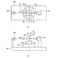
次に、焦点測定器を図12の第1の実施例における焦点距離測定器の説明図に基づいて説明する。なお、図12(a)は焦点距離測定器の概略平面図であり、図12(b)は焦点距離測定器の概略側面図である。 Next, the focus measuring device will be described based on the explanatory view of the focal length measuring device in the first embodiment of FIG. FIG. 12A is a schematic plan view of the focal length measuring device, and FIG. 12B is a schematic side view of the focal length measuring device.
図12において、焦点測定器200は、回転台201、ステージ202、顕微鏡203および照明装置204から構成される。
In FIG. 12, the
回転台201は、回転軸201Aを中心に、その回転台201上に配置されているステージ202と披検レンズ12(マイクロレンズ12)を回転できるように構成されている。このステージ202上には披検レンズ12が、その披検レンズ12の光軸AXが顕微鏡203の光軸と一致するように固定される。ステージ202は、光軸AXと平行する方向に移動できるように構成されている。
The
また、顕微鏡203は、光軸AXと平行する方向に移動できるように構成されており、顕微鏡203の結像点の位置を回転軸201Aの位置とした場合を基準に顕微鏡203の移動量が計測できるように構成されている。
照明装置204は、披検レンズ12に平行光線BTが入射するように光線を出射する。
The
The
次に、焦点距離の測定方法について、図12を用いて説明する。
照明装置204より光線を出射させ、顕微鏡203で披検レンズ12による光線BTの結像を確認しながら、顕微鏡203を披検レンズ12から離れる方向に移動させる。光線BTの結像の大きさが最も小さくなったら、回転台201を微小に回転させても光線BTの結像の位置が変わらないステージ202の位置と顕微鏡203の位置を検出するように、ステージ202と顕微鏡203をそれぞれ別に移動させる。
Next, a method for measuring the focal length will be described with reference to FIG.
A light beam is emitted from the
そして、回転台201を微小に回転させても光線BTの結像の位置が変わらなくなったときの顕微鏡203の回転軸201Aの位置からの移動量Z1を計測する。ここで、移動量Z1は、披検レンズ12の焦点距離Fに相当する。また、このときの回転軸201Aの位置は披検レンズ12の第1主平面に相当する。
Then, the amount of movement Z1 from the position of the
次に、ステージ202の位置は固定したまま、顕微鏡203のみを披検レンズ12へ近づける方向に移動させ、顕微鏡203の結像点が披検レンズ12の面頂点となるように移動させる。そして、顕微鏡203の結像点が披検レンズ12の面頂点となる位置の顕微鏡203の回転軸201Aの位置からの移動量Z2を計測する。
Next, while the position of the
さらに、披検レンズ12の面頂点と物体面までの距離LOを別の方法で測定することにより、披検レンズ12の物体面と主平面との距離SOを、SO=移動量Z2+距離LOより求めることができる。
Further, by measuring the distance LO between the surface vertex of the
以上の焦点距離の測定方法は、ノーダル・スライド法による既知の測定方法である。 The above focal length measurement method is a known measurement method based on the nodal slide method.
本実施例のレンズアレイ10を用いたLEDヘッド3について、結像の解像度示すMTF(Modulation Transfer Function:振幅伝達関数)の測定をしたところ80%以上の値を測定した。
With respect to the
ここで、MTFとは、露光装置の解像度を示し、露光装置中で点灯しているLED素子30の結像のコントラストを示す。100%が結像のコントラストが最も大きく、露光装置としての解像度が高いことを示し、小さいほど光量のコントラストは小さく、露光装置の解像度は低い。
Here, MTF indicates the resolution of the exposure apparatus, and indicates the contrast of image formation of the
MTF(%)は、結像の光量の最大値をEMAX、隣り合う2つの結像の間の光量の最小値をEMINとしたとき、
MTF=(EMAX−EMIN)/(EMAX+EMIN)×100(%)
のように定義される。
MTF (%) is EMAX as the maximum value of the amount of imaged light, and EMIN as the minimum value of the amount of light between two adjacent images.
MTF = (EMAX−EMIN) / (EMAX + EMIN) × 100 (%)
Is defined as follows.
このMTFの測定においては、LEDヘッド3のレンズユニット1の結像面IP上、第2のマイクロレンズ12bの結像面側レンズの頂点から距離LI(mm)離れた位置の結像を顕微鏡デジタルカメラにより撮影し、撮影画像よりLED素子30の結像の光量分布を解析し、このMTFを算出した。
In this MTF measurement, an image formed at a distance LI (mm) away from the apex of the image forming surface side lens of the
また、MTFの測定においては、LED素子30の配列間隔PD=0.0423mmであるLEDヘッド3を用いた。
Further, in the MTF measurement, the
さらに、MTFの値と画像形成装置の画像品質について説明する。 Further, the MTF value and the image quality of the image forming apparatus will be described.
本来、画像形成装置が形成する画像でトナーが乗らない部分は、静電潜像においては電位が十分に高くなければならない。また、LEDヘッドで形成される結像は暗くなければならない。ところが、MTFの値が小さいとLEDヘッドで形成される結像において、暗くなければならない部分にも光線が入射してしまう。 Originally, the portion of the image formed by the image forming apparatus where no toner is applied must have a sufficiently high potential in the electrostatic latent image. In addition, the image formed by the LED head must be dark. However, if the MTF value is small, the light beam is incident on a portion that must be dark in the image formed by the LED head.
光線が入射してしまうと静電潜像においては電位が十分に高くなければならないところの電位が下がってしまい、本来、画像形成装置の画像でトナーが乗らない部分にトナーが付着してしまう。 When the light beam enters, the potential of the electrostatic latent image where the potential must be sufficiently high is lowered, and the toner adheres to the portion of the image forming apparatus where the toner is not originally placed.
画像形成装置の画像でトナーが乗らない部分は、本来、用紙の色である白色によって画像が構成されるが、トナーが付着してしまった部分は、トナーの色が混ざって見えるため、画像形成装置の画像品質が低下する。 In the image forming apparatus image, the portion where no toner is applied is originally composed of the white color of the paper, but the portion where the toner is attached appears to be mixed with the toner color, so image formation The image quality of the device is degraded.
様々な評価を重ねた結果、MTFが80%以上のとき、画像形成装置の画像は筋や濃淡斑のない良好な画像となった。 As a result of various evaluations, when the MTF was 80% or more, the image of the image forming apparatus was a good image without streaks or light and dark spots.
次に、カラーLEDプリンタを用いて本実施例のレンズユニットを実装した画像形成装置の画像を評価したところ、筋や濃淡斑のない良好な画像が得られた。画像形成装置の画像の評価は、印刷領域全面に図13に示した全画素のうち1つおきにドットを形成する画像を形成し、画像品質の良否を評価した。図13において、301はトナーが乗っているドット、302はトナーが乗っていないドットを示している。また、各ドットの間隔PD=0.0423mmである。
Next, when an image of the image forming apparatus on which the lens unit of this example was mounted was evaluated using a color LED printer, a good image free of streaks and shading was obtained. In the image evaluation of the image forming apparatus, an image in which dots are formed every other pixel among all the pixels shown in FIG. 13 is formed on the entire surface of the printing area, and the quality of the image is evaluated. In FIG. 13,
なお、本実施例では、マイクロレンズ12は回転対称高次非球面で構成したが、これに限られることなく、球面を形成するようにしてもよい。また、アナモフィック非球面、放物面、楕円面、双曲面、コーニック面等の曲面を形成してもよい。
In the present embodiment, the
また、レンズアレイ10は一般射出成型により作成したが、圧縮射出成型等、その他の成型法でもよく、切削により形成してもよい。さらに、レンズアレイ10の素材は樹脂を用いているがガラスを用いてもよい。
Moreover, although the
また、遮光板20はポリカーボネートを用いて射出成型により作成したが、これに限られることなく、切削加工により作成してもよく、またエッチングなどで作成してもよい。
Moreover, although the light-shielding
また、発光部としてLED素子30を複数配置したLEDアレイを用いたが、例えば有機EL、半導体レーザーを用いてもよい。
Moreover, although the LED array which has arrange | positioned
以上説明したように、第1の実施例では、物体面OPから第1主平面HF1までの距離SO1の第2主平面HS1から中間像面IMPまでの距離SI1に対する比が、中間像面IMPから第1主平面HF2までの距離SI2の結像面IPから第2主平面HS2までの距離SO2に対する比に等しくなるようにレンズアレイを構成することにより、結像面側のマイクロレンズと結像面との間隔が変化しても結像が分裂されることが抑制され、焦点深度の深い光学系を構成することができるという効果が得られる。 As described above, in the first embodiment, the ratio of the distance SO1 from the object plane OP to the first main plane HF1 to the distance SI1 from the second main plane HS1 to the intermediate image plane IMP is determined from the intermediate image plane IMP. By forming the lens array so as to be equal to the ratio of the distance SI2 to the first main plane HF2 to the distance SO2 from the imaging plane IP to the second main plane HS2, the microlenses and the imaging plane on the imaging plane side are configured. Even if the interval is changed, the image formation is suppressed from being disrupted, and an optical system having a deep focal depth can be obtained.
第1の実施例では、本発明によるレンズユニットを画像形成装置としてのプリンタに適用したものとして説明したが、第2の実施例では読取装置に適用した例を説明する。 In the first embodiment, the lens unit according to the present invention has been described as applied to a printer as an image forming apparatus. In the second embodiment, an example in which the lens unit is applied to a reading apparatus will be described.
第2の実施例の構成を図14の第2の実施例における読取装置の構成を示す概略図に基づいて説明する。なお、上述した第1の実施例と同様の部分は、同一の符号を付してその説明を省略する。 The configuration of the second embodiment will be described with reference to the schematic diagram showing the configuration of the reading apparatus in the second embodiment of FIG. Note that parts similar to those of the first embodiment described above are denoted by the same reference numerals and description thereof is omitted.
図14において、500は、原稿を読取って画像データとしての電子データを生成する読取装置としてのスキャナである。
In FIG. 14,
スキャナ500は、読取ヘッド400、ランプ501、原稿台502、レール503、駆動ベルト505、モータ506等で構成されている。
The
読取ヘッド400は、照明装置としてのランプ501により照射され、原稿の表面で反射した光線を取り込み電子データに変換するものである。ランプ501は、照射した光が原稿の表面で反射し、読取ヘッド400内に取り込まれるように配置されている。
The reading
原稿台502は、電子データが生成される原稿507を載置するものであり、可視光線を透過する素材で形成されている。
The document table 502 is used to place a
レール503は、原稿台502の下方に配置され、読取ヘッド400を移動可能にするものであり、読取ヘッド400は、その一部が複数の滑車504により張架された駆動ベルト505に接続され、モータ506で駆動された駆動ベルト505によりレール503上を移動可能に構成されている。
The
次に、読取ヘッド400の構成を図15の第2の実施例における読取装置の読取りヘッドの構成を示す概略図に基づいて説明する。
Next, the configuration of the
図15において、読取ヘッド400は、レンズユニット1、ラインセンサ401およびミラー402で構成されている。
In FIG. 15, the
ミラー402は、原稿503で反射された光線の光路を折り曲げてその光線をレンズユニット1に入射させるものである。
The
ラインセンサ401は、複数の受光素子が略直線に配置されており、レンズユニット1により形成された原稿画像の結像を電気信号に変換するものである。このラインセンサ401は、レンズユニット1の幅方向の中央を示す中心線CL上に位置するように配置される。
The
また、図16は本実施例の読取ヘッド400の構成および物体面OP(原稿507)と結像面IPとの位置関係を示している。なお、本実施例のレンズユニット1の構成は第1の実施例と同様であり、原稿507の折れにより面間隔が変動し易い距離LOが距離LIに比べて大きくなっている。
FIG. 16 shows the configuration of the
なお、本実施例では、ラインセンサ401は600dpiの解像度であり、受光素子が1インチ当たり600個配置されている。すなわち、受光素子の間隔は0.0423mmである。
In this embodiment, the
上述した構成の作用について説明する。 The operation of the above configuration will be described.
まず、読取装置の動作を図14に基づいて説明する。 First, the operation of the reading apparatus will be described with reference to FIG.
ランプ501が点灯し、原稿507の表面を照射することにより、原稿507の表面で反射した光線が読取ヘッド400内に取り込まれる。モータ506により、駆動ベルト505が駆動して読取ヘッド400とランプ501が図14における左右方向に移動し、読取ヘッド400は原稿507の全面から反射した光線を取り込む。
When the
次に、読取ヘッド400の動作を図15に基づいて説明する。
Next, the operation of the read
原稿507で反射された光線は、原稿台502を透過し、ミラー402で光路が折り曲げられ、レンズユニット1に入射する。レンズユニット1により結像された原稿画像の結像はラインセンサ401上に形成され、ラインセンサ401は形成された原稿画像の結像を電気信号に変換して電子データを生成する。
The light beam reflected by the original 507 passes through the original table 502, the optical path is bent by the
本実施例による読取装置を用いて、図13で示すようにドットの間隔PD=0.0423mm、解像度600dpiの全ドットのうち、1つおきにドットを形成した画像を媒体上の印字領域全面に形成した原稿から電子データを形成したところ、原稿と同一の良好な電子データが得られた。 Using the reading apparatus according to the present embodiment, as shown in FIG. 13, an image in which every other dot is formed among all the dots having a dot interval PD = 0.0423 mm and a resolution of 600 dpi is printed on the entire print area on the medium. When electronic data was formed from the formed original, good electronic data identical to the original was obtained.
なお、本実施例においては、原稿画像を電子データに変換する読取装置としてスキャナを例に説明したが、光学的信号を電気信号に変換するセンサやスイッチ、およびそれらを用いた入出力装置、生体認証装置、通信装置、寸法測定器等であってもよい。 In this embodiment, a scanner is described as an example of a reading device that converts an original image into electronic data. However, sensors and switches that convert optical signals into electric signals, input / output devices using them, and biological It may be an authentication device, a communication device, a dimension measuring device, or the like.
以上説明したように、第2の実施例では、読取装置においても第1の実施例と同様の効果が得られ、原稿の折れ等により、物体面側のマイクロレンズと物体面との間隔が変化しても原稿と同一の電子データを得ることができるという効果が得られる。 As described above, in the second embodiment, the same effect as that of the first embodiment can be obtained in the reading apparatus, and the distance between the microlens on the object plane side and the object plane changes due to document folding or the like. Even in this case, the same electronic data as the original can be obtained.
1 レンズユニット
3 LEDヘッド
5 現像器
7 排出部
9 定着器
10 レンズアレイ
12 マイクロレンズ
20 遮光板
22 開口部
30 LED素子
31 ドライバIC
32 ワイヤ
33 配線基板
34 ホルダ
41 感光体ドラム
42 帯電ローラ
43 クリーニングブレード
51 トナーカートリッジ
60 給紙カセット
61 給紙ローラ
62、63、64 搬送ローラ
65 排出ローラ
80 転写ローラ
81 転写ベルト
DESCRIPTION OF
32
Claims (17)
前記第1のレンズの第1主平面と物体面との距離をSO1、前記第1のレンズの第2主平面と前記中間像面との距離をSI1、前記第2のレンズの第1主平面と前記中間像面との距離をSO2、前記第2のレンズの第2主平面と前記結像面との距離をSI2としたとき、距離SO1の距離SI1に対する比が、距離SI2の距離SO2に対する比に略等しく、前記第1のレンズと前記物体面との間隔が、前記第2のレンズと前記結像面との間隔と異なるように形成されていることを特徴とするレンズユニット。 A lens pair comprising a first lens that forms an inverted image of an object as an intermediate image on the intermediate image plane and a second lens that forms an inverted image of the intermediate image formed by the first lens on the imaging plane. In a lens unit having a lens array arranged in a plurality of substantially straight lines in a direction perpendicular to the optical axis of the lens pair,
The distance between the first principal plane of the first lens and the object plane is SO1, the distance between the second principal plane of the first lens and the intermediate image plane is SI1, and the first principal plane of the second lens. And the intermediate image plane is SO2, and the distance between the second main plane of the second lens and the imaging plane is SI2, the ratio of the distance SO1 to the distance SI1 is the distance SI2 to the distance SO2. The lens unit is characterized in that the distance between the first lens and the object plane is substantially equal to the ratio, and the distance between the second lens and the imaging plane is different.
前記第1のレンズと物体面との距離をLO1、前記第1のレンズと前記中間像面との距離をLI1、前記第2のレンズと前記中間像面との距離をLO2、前記第2のレンズと前記結像面との距離をLI2としたとき、距離LO1の距離LI1に対する比が、距離LI2の距離LO2に対する比に略等しく、前記距離LO1が、前記距離LI2と異なるように形成されていることを特徴とするレンズユニット。 The lens unit according to claim 1, wherein
The distance between the first lens and the object plane is LO1, the distance between the first lens and the intermediate image plane is LI1, the distance between the second lens and the intermediate image plane is LO2, and the second When the distance between the lens and the imaging plane is LI2, the ratio of the distance LO1 to the distance LI1 is substantially equal to the ratio of the distance LI2 to the distance LO2, and the distance LO1 is different from the distance LI2. A lens unit characterized by comprising:
前記それぞれの第1のレンズと第2のレンズとの間に配置される絞りが略直線に複数形成された遮光部材を備え、
二つの前記レンズ対の視野が重なり合うようにしたことを特徴とするレンズユニット。 The lens unit according to claim 1 or 2,
A light-shielding member in which a plurality of stops arranged between the first lens and the second lens are formed in a substantially straight line;
A lens unit characterized in that the fields of view of the two lens pairs overlap each other.
前記レンズ対の配列方向の間隔をP、前記第1のレンズの焦点距離をF、前記第1のレンズの第1主平面と物体面との距離をSO、前記光軸と前記絞りの開口部の内壁との距離の最大値をRAとしたとき、数式22を満たすことを特徴とするレンズユニット。
The distance between the lens pairs in the arrangement direction is P, the focal length of the first lens is F, the distance between the first principal plane of the first lens and the object plane is SO, the optical axis and the aperture of the diaphragm A lens unit that satisfies Formula 22 when the maximum value of the distance to the inner wall of the lens is RA.
前記レンズ対の配列方向の間隔をP、前記第1のレンズの焦点距離をF、前記第1のレンズと物体面との距離をLO、前記光軸と前記絞りの開口部の内壁との距離の最大値をRAとしたとき、数式23を満たすことを特徴とするレンズユニット。
The distance between the lens pairs in the arrangement direction is P, the focal length of the first lens is F, the distance between the first lens and the object plane is LO, and the distance between the optical axis and the inner wall of the aperture of the diaphragm. A lens unit that satisfies Formula 23 when the maximum value of RA is RA.
前記レンズ対の配列方向の間隔をP、前記第1のレンズの第1主平面と物体面との距離をSO、前記第1のレンズの第2主平面と前記中間像面との距離をSI、前記光軸と前記絞りの開口部の内壁との距離の最大値をRAとしたとき、数式24を満たすことを特徴とするレンズユニット。
The distance between the lens pairs in the arrangement direction is P, the distance between the first main plane of the first lens and the object plane is SO, and the distance between the second main plane of the first lens and the intermediate image plane is SI. A lens unit that satisfies Formula 24, where RA is the maximum value of the distance between the optical axis and the inner wall of the aperture opening.
前記レンズ対の配列方向の間隔をP、前記第1のレンズと物体面との距離をLO、前記第1のレンズと前記中間像面との距離をLI、前記光軸と前記絞りの開口部の内壁との距離の最大値をRAとしたとき、数式25を満たすことを特徴とするレンズユニット。
The distance between the lens pairs in the arrangement direction is P, the distance between the first lens and the object plane is LO, the distance between the first lens and the intermediate image plane is LI, the optical axis and the aperture of the diaphragm A lens unit that satisfies Formula 25, where RA is the maximum distance from the inner wall of the lens.
前記レンズ対は、該レンズ対の光軸と直交する方向へ2列に配列され、
前記レンズ対の配列方向の間隔をPY、前記レンズ対の配列方向と直交する方向の間隔をPX、前記第1のレンズの焦点距離をF、前記第1のレンズの第1主平面と物体面との距離をSO、前記光軸と前記絞りの開口部の内壁との距離の最大値をRAとしたとき、数式26を満たすことを特徴とするレンズユニット。
The lens pairs are arranged in two rows in a direction perpendicular to the optical axis of the lens pair,
The interval in the arrangement direction of the lens pairs is PY, the interval in the direction orthogonal to the arrangement direction of the lens pairs is PX, the focal length of the first lens is F, the first main plane of the first lens and the object plane Is a lens unit that satisfies Equation 26, where SO is the distance from the optical axis and RA is the maximum value of the distance between the optical axis and the inner wall of the aperture opening.
前記レンズ対は、該レンズ対の光軸と直交する方向へ2列に配列され、
前記レンズ対の配列方向の間隔をPY、前記レンズ対の配列方向と直交する方向の間隔をPX、前記第1のレンズの焦点距離をF、前記第1のレンズと物体面との距離をLO、前記光軸と前記絞りの開口部の内壁との距離の最大値をRAとしたとき、数式27を満たすことを特徴とするレンズユニット。
The lens pairs are arranged in two rows in a direction perpendicular to the optical axis of the lens pair,
The interval between the lens pairs in the arrangement direction is PY, the interval in the direction orthogonal to the arrangement direction of the lens pairs is PX, the focal length of the first lens is F, and the distance between the first lens and the object plane is LO. A lens unit that satisfies Formula 27, where RA is the maximum value of the distance between the optical axis and the inner wall of the aperture opening.
前記レンズ対は、該レンズ対の光軸と直交する方向へ2列に配列され、
前記レンズ対の配列方向の間隔をPY、前記レンズ対の配列方向と直交する方向の間隔をPX、前記第1のレンズの第1主平面と物体面との距離をSO、前記第1のレンズの第2主平面と前記中間像面との距離をSI、前記光軸と前記絞りの開口部の内壁との距離の最大値をRAとしたとき、数式28を満たすことを特徴とするレンズユニット。
The lens pairs are arranged in two rows in a direction perpendicular to the optical axis of the lens pair,
The interval in the arrangement direction of the lens pairs is PY, the interval in the direction orthogonal to the arrangement direction of the lens pairs is PX, the distance between the first main plane of the first lens and the object plane is SO, and the first lens A lens unit satisfying Equation 28, where SI is the distance between the second principal plane of the lens and the intermediate image plane, and RA is the maximum value of the distance between the optical axis and the inner wall of the aperture opening. .
前記レンズ対は、該レンズ対の光軸と直交する方向へ2列に配列され、
前記レンズ対の配列方向の間隔をPY、前記レンズ対の配列方向と直交する方向の間隔をPX、前記第1のレンズと物体面との距離をLO、前記第1のレンズと前記中間像面との距離をLI、前記光軸と前記絞りの開口部の内壁との距離の最大値をRAとしたとき、数式29を満たすことを特徴とするレンズユニット。
The lens pairs are arranged in two rows in a direction perpendicular to the optical axis of the lens pair,
The distance in the arrangement direction of the lens pairs is PY, the distance in the direction orthogonal to the arrangement direction of the lens pairs is PX, the distance between the first lens and the object plane is LO, and the first lens and the intermediate image plane A lens unit that satisfies Equation 29, where LI is the distance between the optical axis and RA is the maximum distance between the optical axis and the inner wall of the aperture opening.
前記第1のレンズと物体面との距離が、前記第2のレンズと前記結像面との距離より小さいことを特徴とするレンズユニット。 The lens unit according to any one of claims 1 to 11,
The lens unit, wherein a distance between the first lens and the object plane is smaller than a distance between the second lens and the imaging plane.
前記第1のレンズと物体面との距離が、前記第2のレンズと前記結像面との距離より大きいことを特徴とするレンズユニット。 The lens unit according to any one of claims 1 to 11,
The lens unit, wherein a distance between the first lens and the object plane is larger than a distance between the second lens and the imaging plane.
Priority Applications (2)
| Application Number | Priority Date | Filing Date | Title |
|---|---|---|---|
| JP2009251370A JP2011095627A (en) | 2009-10-30 | 2009-10-30 | Lens unit, led head, exposure device, image forming apparatus, and reading apparatus |
| US12/913,423 US8000015B2 (en) | 2009-10-30 | 2010-10-27 | Lens unit, LED head, exposing unit, image forming apparatus, and scanning apparatus |
Applications Claiming Priority (1)
| Application Number | Priority Date | Filing Date | Title |
|---|---|---|---|
| JP2009251370A JP2011095627A (en) | 2009-10-30 | 2009-10-30 | Lens unit, led head, exposure device, image forming apparatus, and reading apparatus |
Publications (2)
| Publication Number | Publication Date |
|---|---|
| JP2011095627A true JP2011095627A (en) | 2011-05-12 |
| JP2011095627A5 JP2011095627A5 (en) | 2012-05-17 |
Family
ID=43925165
Family Applications (1)
| Application Number | Title | Priority Date | Filing Date |
|---|---|---|---|
| JP2009251370A Pending JP2011095627A (en) | 2009-10-30 | 2009-10-30 | Lens unit, led head, exposure device, image forming apparatus, and reading apparatus |
Country Status (2)
| Country | Link |
|---|---|
| US (1) | US8000015B2 (en) |
| JP (1) | JP2011095627A (en) |
Cited By (2)
| Publication number | Priority date | Publication date | Assignee | Title |
|---|---|---|---|---|
| JP2013111786A (en) * | 2011-11-25 | 2013-06-10 | Oki Data Corp | Lens array, lens unit, led head, exposure device, image formation apparatus, and reading apparatus |
| JP2015116820A (en) * | 2013-12-16 | 2015-06-25 | ゼロックス コーポレイションXerox Corporation | Led printhead with relay lens to increase depth of focus |
Families Citing this family (6)
| Publication number | Priority date | Publication date | Assignee | Title |
|---|---|---|---|---|
| US8643950B2 (en) | 2012-03-15 | 2014-02-04 | Blackberry Limited | Lens-based image augmenting optical window with intermediate real image |
| US8953245B2 (en) | 2012-03-15 | 2015-02-10 | Blackberry Limited | Lens-based optical window with intermediate real image |
| JP2013246349A (en) * | 2012-05-28 | 2013-12-09 | Oki Data Corp | Lens unit, exposure device, led head, image forming apparatus, and reading device |
| FR3039628B1 (en) * | 2015-07-30 | 2020-10-16 | Gaggione Sas | MAXIMUM LIGHT INTENSITY NON-IMAGING COLLIMATION SYSTEM |
| WO2020056547A1 (en) * | 2018-09-17 | 2020-03-26 | Fingerprint Cards Ab | Biometric imaging device |
| JP2020148919A (en) * | 2019-03-14 | 2020-09-17 | 株式会社沖データ | Lens unit, exposure apparatus, read head, image formation device and image read device |
Citations (2)
| Publication number | Priority date | Publication date | Assignee | Title |
|---|---|---|---|---|
| JP2000352606A (en) * | 1999-06-11 | 2000-12-19 | Rohm Co Ltd | Lens assembly and picture display device using the same |
| JP2009223186A (en) * | 2008-03-18 | 2009-10-01 | Oki Data Corp | Lens array, led head having the same, exposure device, image forming apparatus and image reading apparatus |
Family Cites Families (3)
| Publication number | Priority date | Publication date | Assignee | Title |
|---|---|---|---|---|
| JP2000221445A (en) | 1999-02-04 | 2000-08-11 | Oki Data Corp | Optical system for optical head |
| US6707613B2 (en) * | 2000-04-05 | 2004-03-16 | Rohm Co., Ltd. | Lens array unit and method of forming image |
| US7898738B2 (en) * | 2007-09-10 | 2011-03-01 | Oki Data Corporation | Lens array, manufacturing method thereof, LED head having lens array, exposure device having LED head, image forming apparatus having exposure device, and reading apparatus |
-
2009
- 2009-10-30 JP JP2009251370A patent/JP2011095627A/en active Pending
-
2010
- 2010-10-27 US US12/913,423 patent/US8000015B2/en not_active Expired - Fee Related
Patent Citations (2)
| Publication number | Priority date | Publication date | Assignee | Title |
|---|---|---|---|---|
| JP2000352606A (en) * | 1999-06-11 | 2000-12-19 | Rohm Co Ltd | Lens assembly and picture display device using the same |
| JP2009223186A (en) * | 2008-03-18 | 2009-10-01 | Oki Data Corp | Lens array, led head having the same, exposure device, image forming apparatus and image reading apparatus |
Cited By (2)
| Publication number | Priority date | Publication date | Assignee | Title |
|---|---|---|---|---|
| JP2013111786A (en) * | 2011-11-25 | 2013-06-10 | Oki Data Corp | Lens array, lens unit, led head, exposure device, image formation apparatus, and reading apparatus |
| JP2015116820A (en) * | 2013-12-16 | 2015-06-25 | ゼロックス コーポレイションXerox Corporation | Led printhead with relay lens to increase depth of focus |
Also Published As
| Publication number | Publication date |
|---|---|
| US8000015B2 (en) | 2011-08-16 |
| US20110102886A1 (en) | 2011-05-05 |
Similar Documents
| Publication | Publication Date | Title |
|---|---|---|
| JP4856199B2 (en) | Lens unit, LED head, exposure apparatus, image forming apparatus, and reading apparatus | |
| JP5584262B2 (en) | Lens unit, LED head, exposure apparatus, image forming apparatus, and reading apparatus | |
| JP5030828B2 (en) | Lens array and LED head, exposure apparatus, image forming apparatus and reading apparatus having the same | |
| JP5848889B2 (en) | Lens unit, LED head, exposure apparatus, image forming apparatus, and reading apparatus | |
| JP5789499B2 (en) | Lens array, lens unit, LED head, exposure apparatus, image forming apparatus, and reading apparatus | |
| JP2010164658A (en) | Lens array, lens unit, led head, exposing unit, image forming apparatus, and reading apparatus | |
| JP2010181686A (en) | Lens array, led head, exposure device, image forming apparatus and reading device | |
| JP2011095627A (en) | Lens unit, led head, exposure device, image forming apparatus, and reading apparatus | |
| JP4714765B2 (en) | Lens array, LED print head, exposure apparatus, image forming apparatus, and reading apparatus | |
| JP4906798B2 (en) | Lens array, LED head, exposure apparatus, image forming apparatus, and reading apparatus | |
| JP2012230252A (en) | Lens array, lens unit, exposure device, image forming apparatus, and reader | |
| JP4868612B2 (en) | Exposure apparatus, LED head, image forming apparatus, and reading apparatus | |
| JP5222161B2 (en) | Lens unit, LED head, exposure apparatus, image forming apparatus, and reading apparatus | |
| JP2010145821A (en) | Lens array, led head, exposure device, image forming apparatus and reader | |
| JP4751922B2 (en) | Lens array unit, optical head, and information device | |
| JP7003723B2 (en) | Lens unit, exposure device, LED head, image forming device, and reading device | |
| JP5775389B2 (en) | Lens array, lens unit, LED head, exposure apparatus, image forming apparatus, and reading apparatus | |
| JP5797014B2 (en) | Lens unit, LED head, image forming apparatus, and reading apparatus | |
| US7719553B2 (en) | Exposure apparatus and image forming apparatus | |
| JP5216109B2 (en) | Lens array and exposure apparatus, image forming apparatus and reading apparatus having the same | |
| JP5261220B2 (en) | Lens array, LED head, exposure apparatus, image forming apparatus, and reading apparatus | |
| JP2012189915A (en) | Lens unit, led head, exposure device, image forming device, and reading device | |
| JP2009216730A (en) | Exposure device, image forming apparatus and reading apparatus | |
| JP2012247566A (en) | Lens array, lens unit, led head, exposure device, image forming apparatus, and reading device | |
| JP2010210716A (en) | Lens unit, lens assembly member, led head, exposure device, image forming apparatus, reader, and method for manufacturing the lens assembly member |
Legal Events
| Date | Code | Title | Description |
|---|---|---|---|
| A521 | Request for written amendment filed |
Free format text: JAPANESE INTERMEDIATE CODE: A523 Effective date: 20120328 |
|
| A621 | Written request for application examination |
Free format text: JAPANESE INTERMEDIATE CODE: A621 Effective date: 20120328 |
|
| A977 | Report on retrieval |
Free format text: JAPANESE INTERMEDIATE CODE: A971007 Effective date: 20130307 |
|
| A131 | Notification of reasons for refusal |
Free format text: JAPANESE INTERMEDIATE CODE: A131 Effective date: 20130514 |
|
| A521 | Request for written amendment filed |
Free format text: JAPANESE INTERMEDIATE CODE: A523 Effective date: 20130712 |
|
| A02 | Decision of refusal |
Free format text: JAPANESE INTERMEDIATE CODE: A02 Effective date: 20130903 |