JP2011084899A - Simple scaffold for climbing up and down column body - Google Patents
Simple scaffold for climbing up and down column body Download PDFInfo
- Publication number
- JP2011084899A JP2011084899A JP2009237192A JP2009237192A JP2011084899A JP 2011084899 A JP2011084899 A JP 2011084899A JP 2009237192 A JP2009237192 A JP 2009237192A JP 2009237192 A JP2009237192 A JP 2009237192A JP 2011084899 A JP2011084899 A JP 2011084899A
- Authority
- JP
- Japan
- Prior art keywords
- scaffold
- column
- lowering
- column body
- peripheral surface
- Prior art date
- Legal status (The legal status is an assumption and is not a legal conclusion. Google has not performed a legal analysis and makes no representation as to the accuracy of the status listed.)
- Withdrawn
Links
Images


Abstract
Description
本発明は、電柱などに登って作業する場合などに、簡便に用いることのできる柱体昇降用簡易足場に関する。 The present invention relates to a simple scaffold for raising and lowering a pillar body that can be used easily when climbing up a utility pole or the like.
従来、電柱には足場ボルトが植設されているが、これはいたずら防止などの観点から、地上から2メートル以上の高さにあるため、電柱上で作業を行う場合、作業者は足場ボルトまで届くだけの高さの梯子が必要であった。そして、梯子から足場ボルトに移って所望の高さまで登るようにしていた。 Conventionally, scaffolding bolts have been planted on utility poles, but from the standpoint of preventing tampering, etc., this is at a height of 2 meters or more from the ground. A ladder that was high enough to reach was needed. Then, the ladder was moved from the ladder to the scaffold bolt so as to climb to a desired height.
しかし、通常、梯子は金属製であり比較的重量物といえるため、その持ち運びは面倒である。したがって、例えば自動車などでは進入できないような場所の電柱に登る必要がある場合などは、作業者の負担がいよいよ大きくなってしまう。また、例えば電柱などが立設されている地面が平らであればよいが、傾斜地に立っている場合、梯子を安定した状態で立て掛けることが難しく、危険を伴うおそれもある。 However, since the ladder is usually made of metal and can be said to be a relatively heavy object, carrying it is troublesome. Therefore, for example, when it is necessary to climb a utility pole in a place that cannot be entered by an automobile or the like, the burden on the worker is finally increased. Further, for example, the ground on which the electric poles are erected may be flat, but when standing on an inclined ground, it is difficult to stand the ladder in a stable state, which may be dangerous.
そこで、電柱に植設された足場ボルトに掛止して該電柱の外周面に巻装されるロープと、該ロープに着脱自在に取着され電柱に登るとき足を載せる複数の足掛部材とからなる簡易梯子が提案された(例えば、特許文献1を参照。)。 Therefore, a rope that is hooked on a scaffolding bolt planted on the power pole and wound around the outer peripheral surface of the power pole, and a plurality of footrest members that are detachably attached to the rope and mount the foot when climbing the power pole The simple ladder which consists of was proposed (for example, refer patent document 1).
しかしながら、上述した簡易梯子は、梯子に比べればコンパクトに収納することもでき、軽量化も図れるものの、その取付けについては、電柱の地上2メートルほどのところに植設されている足場ボルトにロープを掛け、このロープの両側の2本を電柱の反対側へ回し、次いで、足場ボルトの反対側であってこの足場ボルトより下方へ略50cm下がった位置の電柱外周面に、足掛部材を配置するとともに、ロープを足掛部材に設けたロープ溝に張った状態で嵌め込むという作業を次々と行う必要があるなど、極めて面倒であった。 However, although the simple ladder described above can be stored more compactly than the ladder and can be reduced in weight, the rope can be attached to the scaffolding bolt that is installed about 2 meters above the power pole. Hang and turn the two on both sides of the rope to the opposite side of the utility pole, then place the footrest member on the outer circumference of the utility pole at the opposite side of the scaffolding bolt and about 50 cm below the scaffolding bolt At the same time, it has been extremely troublesome, for example, because it is necessary to successively perform the work of fitting the rope in a state of being stretched in the rope groove provided on the footrest member.
さらに、上述した簡易梯子は、電柱に植設されている足場ボルトにロープを掛ける方式のため、例えば、電柱に植設された足場ボルトが欠損していた場合には、簡易梯子そのものを用いることができないし、そもそも、予め所定の高さに足場ボルトが植設された電柱以外では使用することができない。 Furthermore, since the simple ladder mentioned above is a method of hanging a rope on the scaffolding bolts planted on the utility pole, for example, when the scaffolding bolts implanted on the utility pole are missing, use the simplified ladder itself. In the first place, it cannot be used except for a utility pole in which a scaffold bolt has been previously planted at a predetermined height.
本発明は、上記課題を解決し、安全かつ容易に電柱などの柱体に登ることができ、しかも、携帯や運搬が容易で、なおかつ、取扱いや保管などが極めて簡単な柱体昇降用簡易足場を提供することを目的としている。 The present invention solves the above-mentioned problems, can be climbed on a pole body such as a utility pole safely and easily, and is easy to carry and carry, and is very easy to handle and store, etc. The purpose is to provide.
(1)本発明は、柱体の周面に当接させる当接体と、この当接体に鈍角に連接され、前記柱体の周面から上り勾配で突出するように延在する足場本体と、この足場本体にスライド自在に取付けられ、前記柱体の周面に巻回した連結帯の緊張度合を可変に連結可能とした締結体と、を備えることを特徴とする柱体昇降用簡易足場とした。 (1) The present invention relates to an abutment body that abuts on the peripheral surface of the column body, and a scaffold body that is connected to the abutment body at an obtuse angle and extends so as to protrude upward from the peripheral surface of the column body. And a fastening body that is slidably attached to the scaffold main body and is capable of variably connecting the tension of the connecting band wound around the peripheral surface of the column body. Scaffolding.
(2)また、本発明は、上記(1)の柱体昇降用簡易足場において、前記締結体は、前記足場本体に遊嵌される短筒部と、この短筒部の一側に形成され、前記連結帯の一端側を連結する第1連結部と、前記短筒部の他側に形成され、前記柱体の周面に巻回した連結帯の他端側を連結する第2連結部と、先端が前記当接体の前面に当接するように、前記短筒部に設けたナット体に螺合させたボルト体と、を具備することを特徴とする。 (2) Further, in the simple scaffold for lifting and lowering a column body according to (1), the fastening body is formed on a short cylinder part loosely fitted on the scaffold main body and on one side of the short cylinder part. A first connecting part that connects one end side of the connecting band and a second connecting part that is formed on the other side of the short cylinder part and connects the other end side of the connecting band wound around the peripheral surface of the column body And a bolt body screwed into a nut body provided in the short cylinder portion so that the tip abuts against the front surface of the abutment body.
(3)また、本発明は、上記(1)又は(2)の柱体昇降用簡易足場において、前記足場本体の上面に、滑り止めと水抜きとを兼用する複数の孔を形成したことを特徴とする。 (3) Further, in the simple scaffold for raising and lowering the column body according to (1) or (2), the present invention is such that a plurality of holes that are used for both slip prevention and drainage are formed on the upper surface of the scaffold main body. Features.
(4)また、本発明は、上記(1)〜(3)の柱体昇降用簡易足場において、前記連結帯を、金属製の鎖としたことを特徴とする。 (4) Moreover, the present invention is characterized in that in the simple scaffold for raising and lowering a pillar body according to the above (1) to (3), the connecting band is a metal chain.
本発明によれば、電柱などの柱体への取り付けが容易で、安全に柱体などを昇降することができ、しかも、携帯や運搬が容易で、なおかつ、取扱いや保管などが極めて簡単な柱体昇降用簡易足場を提供することができる。 According to the present invention, a column that can be easily attached to a pole body such as a utility pole, can safely be moved up and down, is easy to carry and carry, and is extremely easy to handle and store. A simple scaffold for raising and lowering a body can be provided.
以下、本実施形態に係る柱体昇降用簡易足場について、図面を参照しながら具体的に説明する。 Hereinafter, the simple scaffold for raising and lowering a column body according to the present embodiment will be specifically described with reference to the drawings.
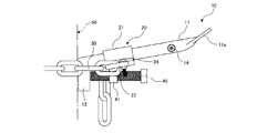
本実施形態に係る柱体昇降用簡易足場10(以下、単に「簡易足場10」とする場合がある)は、柱体50に簡便に取り付け、これを足場として利用して当該柱体50に登れるようにしたものである。本実施形態に係る簡易足場10は金属製であり、図1〜3に示すように、足場本体11、当接体12及び締結体20と、連結体としての鎖30(以下、「チェーン30」という)とを具備し、足場本体11の基端に当接体12が連接されて側面視略L字状に形成されている。
A
足場本体11は、矩形金属板の左右長手側縁を下方へ折曲するとともに、その基端部に柱体50と当接する当接体12を連接している。そして、足場本体11は、図示するように、当接体12を柱体50の周面に当接させた状態で、柱体50の周面から鈍角の上り勾配で突出するようにして取り付けられる。さらに、柱体50から外方に突出する足場本体11の先端部11aは、さらに上方に折り曲げた形状として、足場本体11に置かれた作業者の足が、先端部11aから外側へ滑り難いようにしている。なお、足場本体11と当接体12との取付角度は、100〜120度程度が望ましく、本実施形態では110度に設定している。
The scaffold
また、足場本体11の上面、すなわち作業者の足との接触面には複数の孔13が穿たれている。この孔13は、滑り止めと水抜きとを兼用するものであり、通常は滑り止めとして機能するが、例えば、雨天時などには、足場本体11上に溜まる雨水などの水抜きをして、作業者の足裏が滑ることを防止するようにしている。なお、足場本体11に所定の強度を保った状態で複数の孔13を穿つことにより、柱体昇降用簡易足場10の軽量化を計ることもでき、携帯性をも高めている。
In addition, a plurality of
締結体20は、足場本体11に遊嵌される断面視略矩形形状の短筒部21と、この短筒部21の一側に形成され、連結帯として複数の円環が連結されたチェーン30の一端側を連結する第1連結部22と、短筒部21の他側に形成され、柱体50の周面に巻回したチェーン30の他端側を連結する第2連結部23と、先端が当接体12の前面に当接するように、短筒部21に設けたナット体41に螺合させたボルト体40と、により構成されている。ここで、当接体12の前面とは、簡易足場10の使用状態で、柱体50の周面と当接する面に反対側をなす面である。
The fastening
短筒部21は、足場本体11の先端部11aから足場本体11にスライド自在に遊嵌されている。また、足場本体11には、短筒部21が脱落しないように、抜け止め手段が設けられている。本実施形態では、抜け止め手段として、抜け止ビス14を足場本体11の側部に取り付けている。つまり、この抜け止ビス14を外した状態では、短筒部21は足場本体11の先端部11aから簡単に嵌合できるが、一旦足場本体11に嵌合された短筒部21は、抜け止ビス14を足場本体11の側部に取り付けることで、この抜け止ビス14と当接体12との間のみをスライド自在となるようにしている。
The
短筒部21の左右両側には、それぞれ係止用凹部25が形成された第1連結部22と第2連結部23とが翼状に設けられている。また、一側に形成された第1連結部22には、チェーン30の抜け止め手段としての連結ビス24が設けられている。この連結ビス24を外して、チェーン30の一側端部を第1連結部22の係止用凹部25に係合させて連結した後に、チェーン30と当接する連結ビス24を取り付けることで、チェーン30は係止用凹部25に係合された状態で第1連結部22に対して自由に動くことができるが、抜け方向への移動は規制されるため、第1連結部22からは決して外れることがない構成となっている。
On both the left and right sides of the
一方、短筒部21の他側に形成された第2連結部23は、作業者によるチェーン30の他端側を係止用凹部25に係合したり係合を解除したりできるようにしている。このため、簡易足場10を使用する作業者は、柱体50の周面に巻回したチェーン30の他端側の任意の位置において、チェーン30を第2連結部23に連結したり連結を解除したりできる。
On the other hand, the second connecting
また、短筒部21の下面、つまり、作業者が足を載置する側の面の裏面には、ナット体41が固着されている。そして、このナット体41に、当接体12の前面に、先端が当接するようにボルト体40を螺合させている。
A
このボルト体40をナット体41に対して締める方向、つまり、右回り方向に回転させると、締結体20は足場本体11の先端部11aの方向、すなわち柱体50から離隔する方向にスライドする。これにより、柱体50の周面に巻回したチェーン30の緊張度合いは高くなり、足場本体11は柱体50の任意に位置に固定される。
When the
一方、ボルト体40をナット体41に対して緩める方向、つまり、左回り方向に回転させると、締結体20は足場本体11の当接体12の方向、すなわち柱体50に近接する方向にスライドする。これにより、柱体50の周面に巻回したチェーン30の緊張度合が緩み、足場本体11の柱体50への固定は解除される。
On the other hand, when the
すなわち、本実施形態における柱体昇降用簡易足場10は、柱体50の任意の高さの周面に、第1連結部22の係止用凹部25に一端を連結したチェーン30を巻回して、所定長さに整えたチェーン30の他端側を第2連結部23の係止用凹部25に連結するとともに、ボルト体40を回転させて、短筒部21をスライドさせることにより、チェーン30の緊張度合いを調整して、柱体50への足場本体11の着脱を自在としている。
That is, the
つまり、連結帯としてのチェーン30の最大長さ以内であれば、異なる太さをもつ複数種類の柱体50に対して、柱体昇降用簡易足場10の着脱を可能としている。
That is, as long as it is within the maximum length of the
ここで、さらに図4〜6を参照して、本実施形態における柱体昇降用簡易足場10の取り付けの手順、及び簡易足場10の使用方法について、さらに詳細に説明する。なお、ここでは、柱体50を電柱60として、電柱60に基低部から所定高さ(例えば、2m)に設けられた足場ボルト70までの間に、複数の簡易足場10を取り付ける場合を一例として説明する。
Here, with reference to FIGS. 4-6 further, the procedure of attachment of the
図4に示すように、本実施形態における柱体昇降用簡易足場10は、電柱60の任意の高さの周面60aに当接体12を当接させた状態で、連結帯としてのチェーン30を、その一端側を固定されている第1連結部22から、周面60aを右回りに巻回して、その他端側を第2連結部23に連結させる。
As illustrated in FIG. 4, the column body lifting / lowering
このとき、チェーン30は予め定められた大きさの円環の集合体であるため、完全に電柱60の周面60aに密着させることは出来ない。したがって、作業者はなるべくチェーン30の弛みが少なくなるように、チェーン30の他端側の位置を調整して、第2連結部23に連結させることが望まれる。
At this time, since the
そして、この状態において、短筒部21の下部に設けられたボルト体40をチェーン30の緊張度合いが最大となるまで、スパナ又はメガネレンチなどの工具により締め込む。すなわち、ボルト体40を時計回りに回転させ、図5に示すように、電柱60に対してチェーン30をしっかりと緊張させた状態で簡易足場10を取り付ける。
In this state, the
これにより、チェーン30は電柱60の周面60aに密着するとともに、簡易足場10の当接体12が電柱60の周面60aに密着し、簡易足場10が電柱60に固定される。この状態おいて、作業者が簡易足場10の足場本体11に体重をかけると、作業者の体重の負荷によるモーメントが、足場本体11から当接体12に伝わり、当接体12と電柱60の周面60aとの密着度は増幅されるため、当該簡易足場10が電柱60の周面60aからずれたり、脱落したりすることはない。
Accordingly, the
しかも、足場本体11は、電柱60の周面からは鈍角の上り勾配で突出しているため、作業者が足を掛けても、足場本体11が少なくとも水平状態よりも下り勾配状態にはならず、作業者は安心して足を掛けることができる。
In addition, since the
そして、取り付けた簡易足場10の上方位置に、上述した取り付け手順を繰り返して、必要数の簡易足場10を新しい足場として固定する。すなわち、取り付けた簡易足場10の上方所定高さ(例えば、50cm)の位置であって、電柱60の中心に対して対称となる反対側位置に、さらなる簡易足場10を取り付けていくのである。
And the attachment procedure mentioned above is repeated in the upper position of the attached
このようにして、電柱60に対し、基低部から所定高さ(例えば、2m)に設けられた足場ボルト70までの間に、複数の簡易足場10を取り付けることができ、図6に示すように、電柱60の足場ボルト70が立設されていない部分に取り付けられた複数の簡易足場10を利用して、作業者は容易に電柱60を昇降することができる。
In this way, a plurality of
また、作業が終了した場合は、上述した手順とは逆に、上部に固定された簡易足場10から順番に、短筒部21の下面に設けられたボルト体40を、スパナ又はメガネレンチなどの工具により、緩める方向、つまり、反時計回りに回転させて、チェーン30の緊張度合いを緩めて、チェーン30と第2連結部23との連結を解除することで、容易に簡易足場10を外すことができる。
In addition, when the work is completed, the
そして、外した簡易足場10は、全て一纏めにして適宜収納すれば、持ち運び及び保管も簡単である。
And if the removed
なお、上述してきた図4〜図6を用いた説明では、電柱60の足場ボルト70が立設されていない部分に簡易足場10を用いることを一例として説明してきたが、簡易足場10が設置されるのは電柱60に限定されるものではなく、前述したように柱体50であれば適用可能である。すなわち、作業者が昇降して作業を行う必要のある柱体50であれば、例えば、信号機、道路標識、街灯などに本実施形態に係る簡易足場10を用いることもできる。しかも、柱形状としては必ずしも円柱に限るものではなく、断面視異形形状の柱であっても構わない。
In the description using FIGS. 4 to 6 described above, the
また、本実施形態においては、連結帯としてチェーン30を用いたが、本発明はこれに限定されるものではなく、簡易足場10を柱体に固定できるものであれば、例えば、金属性あるいはゴムなどの樹脂製のロープ、バンドなどを用いてもよい。
In the present embodiment, the
なお、本実施形態における一組のボルト体40及びナット体41は、一般的な構成としたが、例えば、戻り防止機能を備えたボルト体40及びナット体41を用いて、さらなる安全性の向上を図ることもできる。
In addition, although the one
上述してきた実施形態より、以下の柱体昇降用簡易足場10が実現できる。
From the embodiment described above, the following
柱体50の周面に当接させる当接体12と、この当接体12に鈍角に連接され、柱体50の周面から上り勾配で突出するように延在する足場本体11と、この足場本体11にスライド自在に取付けられ、柱体50の周面に巻回した連結帯としてのチェーン30の緊張度合を可変に連結可能とした締結体20と、を備えた柱体昇降用簡易足場10。
An
かかる構成の柱体昇降用簡易足場10を用いることにより、使用者が足場本体11に体重をかけると当接体12が柱体50の周面に密着して、当該柱体昇降用簡易足場10の使用中の脱落を防ぐことができる。また、柱体50の周面に巻回した連結帯としてのチェーン30の緊張度合を可変にするだけで、柱体50への柱体昇降用簡易足場10の着脱を可能としているため、柱体昇降用簡易足場10を着脱する作業性がよい。
By using the simple column lifting / lowering
また、締結体20は、足場本体11に遊嵌される短筒部21と、この短筒部21の一側に形成され、連結帯としてのチェーン30の一端側を連結する第1連結部22と、短筒部21の他側に形成され、柱体50の周面に巻回したチェーン30の他端側を連結する第2連結部23と、先端が当接体12の背面に当接するように、短筒部21に設けたナット体41に螺合させたボルト体40と、を具備する柱体昇降用簡易足場10。
Moreover, the
かかる構成により、柱体50への柱体昇降用簡易足場10の着脱が、ボルト体40を任意の方向に回転させるだけで行えるため、柱体昇降用簡易足場10の着脱作業が簡易であり、また、そのための工具もボルト体40の規格に合ったスパナやメガネレンチなどの最小限の工具で済み、特に電柱などで高所作業を行うときに、無駄な工具を持ち運ぶことがない。
With this configuration, the column body lifting / lowering
また、足場本体11の上面に、滑り止めと水抜きとを兼用する複数の孔13を形成した柱体昇降用簡易足場10。
Moreover, the
かかる構成により、例えば、雨天時での作業においても、利用者が足を滑らせることを防ぐことができ、安全な柱体昇降用簡易足場10とすることができる。
With this configuration, for example, it is possible to prevent the user from sliding his / her foot even during work in rainy weather, and the
また、連結帯としてのチェーン30を、金属製の鎖とした柱体昇降用簡易足場10。
Moreover, the
かかる構成により、連結帯として安価で耐久性の高い金属性(例えば、亜鉛メッキをした鉄)の鎖を用いることで、対費用効果に優れた柱体昇降用簡易足場10とすることができる。
With such a configuration, by using an inexpensive and highly durable metallic (for example, galvanized iron) chain as the connecting band, the column scaffolding
以上、本発明の好ましい実施形態について説明したが、本発明は上述してきた実施形態に限定されるものではなく、特許請求の範囲に記載された本発明の要旨の範囲内において、種々の変形・変更が可能である。 The preferred embodiments of the present invention have been described above. However, the present invention is not limited to the above-described embodiments, and various modifications and changes can be made within the scope of the gist of the present invention described in the claims. It can be changed.
10 柱体昇降用簡易足場
11 足場本体
11a 先端部
12 当接体
13 孔
14 抜け止ビス
20 締結体
21 短筒部
22 第1連結部
23 第2連結部
24 連結ビス
30 チェーン
40 ボルト体
41 ナット体
50 柱体
DESCRIPTION OF
Claims (4)
この当接体に鈍角に連接され、前記柱体の周面から上り勾配で突出するように延在する足場本体と、
この足場本体にスライド自在に取付けられ、前記柱体の周面に巻回した連結帯の緊張度合を可変に連結可能とした締結体と、
を備えることを特徴とする柱体昇降用簡易足場。 An abutting body that abuts on the circumferential surface of the column body;
A scaffold main body connected to the contact body at an obtuse angle and extending so as to protrude from the peripheral surface of the column body with an upward slope;
A fastening body that is slidably attached to the scaffold main body and that can variably connect a tension degree of a connection band wound around the peripheral surface of the column body,
A simple scaffold for lifting and lowering a column body.
前記足場本体に遊嵌される短筒部と、
この短筒部の一側に形成され、前記連結帯の一端側を連結する第1連結部と、
前記短筒部の他側に形成され、前記柱体の周面に巻回した連結帯の他端側を連結する第2連結部と、
先端が前記当接体の前面に当接するように、前記短筒部に設けたナット体に螺合させたボルト体と、
を具備することを特徴とする請求項1記載の柱体昇降用簡易足場。 The fastening body is
A short tube portion loosely fitted to the scaffold body;
A first connecting part formed on one side of the short cylinder part and connecting one end side of the connecting band;
A second connecting portion that is formed on the other side of the short cylindrical portion and connects the other end side of the connecting band wound around the peripheral surface of the column;
A bolt body screwed into a nut body provided in the short cylindrical portion so that the tip abuts on the front surface of the abutting body;
The simple scaffold for raising and lowering a pillar body according to claim 1.
Priority Applications (1)
| Application Number | Priority Date | Filing Date | Title |
|---|---|---|---|
| JP2009237192A JP2011084899A (en) | 2009-10-14 | 2009-10-14 | Simple scaffold for climbing up and down column body |
Applications Claiming Priority (1)
| Application Number | Priority Date | Filing Date | Title |
|---|---|---|---|
| JP2009237192A JP2011084899A (en) | 2009-10-14 | 2009-10-14 | Simple scaffold for climbing up and down column body |
Publications (1)
| Publication Number | Publication Date |
|---|---|
| JP2011084899A true JP2011084899A (en) | 2011-04-28 |
Family
ID=44078047
Family Applications (1)
| Application Number | Title | Priority Date | Filing Date |
|---|---|---|---|
| JP2009237192A Withdrawn JP2011084899A (en) | 2009-10-14 | 2009-10-14 | Simple scaffold for climbing up and down column body |
Country Status (1)
| Country | Link |
|---|---|
| JP (1) | JP2011084899A (en) |
Cited By (2)
| Publication number | Priority date | Publication date | Assignee | Title |
|---|---|---|---|---|
| CN110939262A (en) * | 2019-10-24 | 2020-03-31 | 中建八局第四建设有限公司 | External hanging type external scaffold |
| JP2021052945A (en) * | 2019-09-27 | 2021-04-08 | 日本リーテック株式会社 | Foothold metal fitting which also serves as fitting metal fitting for fall prevention device for steel pipe beam |
-
2009
- 2009-10-14 JP JP2009237192A patent/JP2011084899A/en not_active Withdrawn
Cited By (4)
| Publication number | Priority date | Publication date | Assignee | Title |
|---|---|---|---|---|
| JP2021052945A (en) * | 2019-09-27 | 2021-04-08 | 日本リーテック株式会社 | Foothold metal fitting which also serves as fitting metal fitting for fall prevention device for steel pipe beam |
| JP7134439B2 (en) | 2019-09-27 | 2022-09-12 | 日本リーテック株式会社 | Fall prevention device mounting bracket for steel pipe beam and scaffolding bracket |
| CN110939262A (en) * | 2019-10-24 | 2020-03-31 | 中建八局第四建设有限公司 | External hanging type external scaffold |
| CN110939262B (en) * | 2019-10-24 | 2021-10-08 | 中建八局第四建设有限公司 | External hanging type external scaffold |
Similar Documents
| Publication | Publication Date | Title |
|---|---|---|
| US10125507B2 (en) | Fall protection system | |
| US10760338B2 (en) | Ladder securing apparatuses, ladders incorporating same and related methods | |
| CA2636996C (en) | Ladder docking device | |
| CA2657290C (en) | Safety scaffolding | |
| US9273515B2 (en) | Roofing ladder with a modular angularly adjustable platform | |
| JP2013192402A (en) | Electric pole ascending/descending device | |
| US20140020979A1 (en) | Step extension assembly for tree stand and kit including the same | |
| JP2011084899A (en) | Simple scaffold for climbing up and down column body | |
| US20190078339A1 (en) | Adjustable roofing scaffold system and method of use | |
| US6019330A (en) | Roof guard device for lifting objects on to a roof | |
| JP4524434B2 (en) | Columnar lifting tool | |
| KR200466180Y1 (en) | working scaffolding for telegraph pole | |
| US6648570B2 (en) | Lifting and installing streetlight poles | |
| EP3245376B1 (en) | Fencing bracket | |
| JP3208865U (en) | Scaffolding for foundation work | |
| EP2407610A2 (en) | Scaffold and ramp | |
| CN105569441B (en) | A kind of substation's rail bar fixing bracket | |
| US6761246B2 (en) | Methods and apparatus for mounting a work platform to a ladder | |
| CN211110773U (en) | Multifunctional lifting equipment | |
| KR200413433Y1 (en) | A Width pipe Ladder Construct Clamp set | |
| US20230235627A1 (en) | A coupling device for a ladder | |
| EP2832937B1 (en) | Anti-fall safety equipment, in particular for realizing floors in residential housing | |
| WO2010046670A1 (en) | Stand assembly | |
| JP3050686U (en) | Stepladder and its anchor | |
| KR200402099Y1 (en) | A step bolt |
Legal Events
| Date | Code | Title | Description |
|---|---|---|---|
| A300 | Withdrawal of application because of no request for examination |
Free format text: JAPANESE INTERMEDIATE CODE: A300 Effective date: 20130108 |