JP2011084262A - Front pillar structure, manufacturing method of front pillar component member, and manufacturing method of front pillar - Google Patents
Front pillar structure, manufacturing method of front pillar component member, and manufacturing method of front pillar Download PDFInfo
- Publication number
- JP2011084262A JP2011084262A JP2009294127A JP2009294127A JP2011084262A JP 2011084262 A JP2011084262 A JP 2011084262A JP 2009294127 A JP2009294127 A JP 2009294127A JP 2009294127 A JP2009294127 A JP 2009294127A JP 2011084262 A JP2011084262 A JP 2011084262A
- Authority
- JP
- Japan
- Prior art keywords
- pillar
- front pillar
- flange
- portions
- curved surface
- Prior art date
- Legal status (The legal status is an assumption and is not a legal conclusion. Google has not performed a legal analysis and makes no representation as to the accuracy of the status listed.)
- Granted
Links
Images


Classifications
-
- B—PERFORMING OPERATIONS; TRANSPORTING
- B62—LAND VEHICLES FOR TRAVELLING OTHERWISE THAN ON RAILS
- B62D—MOTOR VEHICLES; TRAILERS
- B62D25/00—Superstructure or monocoque structure sub-units; Parts or details thereof not otherwise provided for
- B62D25/04—Door pillars ; windshield pillars
Abstract
Description
本発明は、フロントピラーの構造、フロントピラー構成部材の製造方法及びフロントピラーの製造方法に関し、詳しくは、自動車のフロントピラーの構造、自動車のフロントピラー構成部材の製造方法、及び自動車のフロントピラーの製造方法に関する。 The present invention relates to a structure of a front pillar, a method of manufacturing a front pillar component, and a method of manufacturing a front pillar, and more particularly, to a structure of a front pillar of a vehicle, a method of manufacturing a front pillar component of a vehicle, and a front pillar of a vehicle. It relates to a manufacturing method.
従来、自動車のフロントピラーの構造では特許文献1が公知である。従来のフロントピラーの構成を図18を参照して説明する。図18はフロントピラー100の軸線方向(長手方向)から見た断面形状である。図18に示すように、フロントピラー100は、車体外側部を構成するピラーアウタパネル110と、フロントピラー100の車体内側部を構成するピラーインナパネル120と、ピラーアウタパネル110・ピラーインナパネル120間に介在して配置されたフロントピラー補強部材130を備える。ピラーアウタパネル110とピラーインナパネル120とにより閉断面部140が形成されている。
Conventionally, Patent Document 1 is known for a structure of a front pillar of an automobile. A configuration of a conventional front pillar will be described with reference to FIG. FIG. 18 is a cross-sectional shape viewed from the axial direction (longitudinal direction) of the
ピラーアウタパネル110、ピラーインナパネル120、及びフロントピラー補強部材130は、前部のフランジ部110a,120a,130a、及び後部のフランジ部110b,120b,130bが重ね合わされてスポット溶接により接合されている。ピラーアウタパネル110のフランジ部110aと、フランジ部110bとの中間部110cは、車室外側方へ突出するように断面突形に形成されている。中間部110cとフランジ部110b間の後側壁110dには外側方へ向けて段部110eが形成されている。
The pillar
フロントピラー補強部材130のフランジ部130aとフランジ部130bと中間部130cは車室外側方へ突出するように断面突形に形成されている。
又、ピラーインナパネル120において、フランジ部120a、120bの中間部120cは、車室内側方へ若干突出するように断面突形に形成されている。
The
Further, in the pillar
ピラーインナパネル120の車室内方にはピラーガーニッシュ150が配置されており、フロントピラー100の車室内側部が被覆されている。フランジ部110b,120b,130bには、オープニングウエザストリップ160が取付けられており、図示しないフロントサイドドアに密着可能である。又、ピラーアウタパネル110のフランジ部110aには、ウインドシールドガラス170が接着剤180にて接着されている。
A
従来、スポット溶接ガンにてフランジ部110a、130a,120aをスポット溶接を行う場合、スポット溶接ガンと、ピラーインナパネル120の中間部120cとの干渉をさけるために、前記中間部120cの車室内側方への突出量を小さくしている。しかし、単に、中間部120cの車室内側方への突出量を小さくすると、閉断面部140の断面積が小さくなり、フロントピラー全体の剛性に影響が出るため、ピラーアウタパネル110の中間部110cの前後方向の幅を長くして、フロントピラー100に必要な剛性が得られるように閉断面部140の断面積を確保するようにしている。
Conventionally, when spot welding is performed on the
ところが、ピラーアウタパネル110の中間部110cの前後方向の幅を長くした場合、運転座席にいる運転者にはフロントピラーを介しての車外の視界が悪くなる問題があった。
However, when the width in the front-rear direction of the
本発明の目的は、フロントピラーの前後方向の長さを短くでき、すなわち、細幅化でき、この結果、運転者からのフロントピラーを介しての車外の視界を良好にして悪化させることがないフロントピラーの構造、フロントピラー構成部材の製造方法及びフロントピラーの製造方法を提供することにある。 The object of the present invention is to reduce the length of the front pillar in the front-rear direction, that is, to reduce the width thereof. As a result, the visibility outside the vehicle through the front pillar from the driver is improved and not deteriorated. An object of the present invention is to provide a structure of a front pillar, a method of manufacturing a front pillar component, and a method of manufacturing a front pillar.
上記問題点を解決するために、請求項1に記載の発明は、前後両部に第1、第2フランジ部を有し、中間部が車室外側方に突出したピラーアウタパネルと、前後両部に第3、第4フランジ部を有し、中間部が車室外側方に突出したフロントピラー構成部材と、前後両部に第5、第6フランジ部を有するピラーインナパネルとを前後方向に順に位置するように連結固定し、さらに、前記フロントピラー構成部材の前後両部の第3、第4フランジ部同士を接合することにより、閉断面構造を有するフロントピラーを構成し、該フロントピラーの車室内側をピラーガーニッシュで覆うフロントピラーの構造において、前記フロントピラー構成部材の第3フランジ部を前記ピラーガーニッシュの前後方向の中間部と相対するように配置し、前記フロントピラー構成部材の第3、第4フランジ部間に、ウインドシールドガラスを支持する支持面を備えたことを特徴とするフロントピラーの構造を要旨とするものである。 In order to solve the above problems, the invention described in claim 1 includes a pillar outer panel having first and second flange portions at both front and rear portions, and an intermediate portion protruding outward from the vehicle compartment, and both front and rear portions. The front pillar component member having the third and fourth flange portions and the intermediate portion projecting outward from the passenger compartment and the pillar inner panel having the fifth and sixth flange portions on the front and rear portions are sequentially arranged in the front-rear direction. A front pillar having a closed cross-sectional structure is formed by connecting and fixing the two so as to be positioned, and joining the third and fourth flanges of the front and rear parts of the front pillar component member. In the structure of the front pillar that covers the indoor side with a pillar garnish, the third flange portion of the front pillar component member is disposed so as to face the middle portion in the front-rear direction of the pillar garnish, and the front The third pillar structure member, between the fourth flange portion, in which the gist of the structure of the front pillar, characterized in that it comprises a support surface for supporting a windshield glass.
請求項2の発明は、請求項1において、前記閉断面構造は、前記第3、第4フランジ部が合掌状に連結され、前記第3フランジ部から前方へ延びる凹面を備える第1曲面部が形成され、前記第1曲面部に連結されて前記支持面を含み凸面を備える第2曲面部が形成され、前記第4フランジ部から外側方へ延びる凹面を備える第3曲面部が形成され、前記第3曲面部から前方へ屈曲された凸面を備える第4曲面部が形成され、前記フロントピラー構成部材の中間部が前記第2曲面部と第4曲面部間を連結することを特徴とする。 According to a second aspect of the present invention, in the closed cross-sectional structure according to the first aspect, the first curved surface portion includes a concave surface extending forward from the third flange portion, and the third and fourth flange portions are connected in a palm shape. A second curved surface portion formed with a convex surface including the support surface and connected to the first curved surface portion is formed, and a third curved surface portion with a concave surface extending outward from the fourth flange portion is formed, A fourth curved surface portion having a convex surface bent forward from the third curved surface portion is formed, and an intermediate portion of the front pillar component member connects the second curved surface portion and the fourth curved surface portion.
請求項3の発明は、請求項2において、前記フロントピラー構成部材の中間部は、面取り部を含み、該面取り部は、前記フロントピラー構成部材の長手方向の中央部では、前記フロントピラー構成部材の長手方向の両端部よりも、第3、第4フランジ部からの離間距離が短く、該中央部から前記フロントピラー構成部材の長手方向の両端部に行くほど第3、第4フランジ部からの距離が長くなるように膨出した部位に配置されていることを特徴とする。 According to a third aspect of the present invention, in the second aspect of the present invention, the intermediate portion of the front pillar component member includes a chamfered portion, and the chamfered portion is the front pillar component member at a central portion in the longitudinal direction of the front pillar component member. The distance from the third and fourth flange portions is shorter than the both ends in the longitudinal direction, and the distance from the third and fourth flange portions increases from the central portion to both ends in the longitudinal direction of the front pillar component member. It arrange | positions in the site | part which bulged so that distance may become long, It is characterized by the above-mentioned.
請求項4の発明は、金属板に対して、長手方向に延びる第1側縁部と第2側縁部が同長手方向に延びる仮想の基準線を中心線とし、かつ前記第1側縁部と第2側縁部が同じ円弧状の凹部をそれぞれ備えるように形成する第1工程と、前記金属板の前記基準線から第1側縁部までの第1領域では、前記円弧状の凹部に平行な第1折曲げ線上で曲げて、基準線に近位の第1近位領域から第1側板部を立設し、前記金属板の前記基準線から第2側縁部までの第2領域では、前記第2側縁部の円弧状の凹部に平行な第2折曲げ線上で曲げて、基準線に近位の第2近位領域から第2側板部を前記第1側板部と同方向に立設する第2工程と、前記第1、第2近位領域内の一部にそれぞれ含まれる領域であって、前記基準線を中心線にする前記長手方向に延びる領域(以下、中間領域という)に対して、前記第1、第2側板部の立設方向とは反対方向へ押圧して前記長手方向の両端部に行くほど、膨出量が増加する膨出部を形成し、かつ、第1、第2側縁部に設けられたフランジ部同士で当接させる第3工程を含むフロントピラー構成部材の製造方法を要旨とするものである。 According to a fourth aspect of the present invention, the first side edge and the first side edge extending in the longitudinal direction are centered on a virtual reference line extending in the longitudinal direction with respect to the metal plate. And the first step of forming the second side edge portion so as to have the same arc-shaped concave portion, and the first region from the reference line to the first side edge portion of the metal plate in the arc-shaped concave portion. Bending on a parallel first fold line, a first side plate portion is erected from a first proximal region proximal to the reference line, and a second region from the reference line to the second side edge of the metal plate Then, the second side plate portion is bent in the same direction as the first side plate portion from the second proximal region proximal to the reference line by bending on a second fold line parallel to the arc-shaped concave portion of the second side edge portion. A second step of standing on the first and second regions of the first and second proximal regions, each extending in the longitudinal direction with the reference line as a center line. Bulging amount increases as it goes to both ends in the longitudinal direction by pressing in the opposite direction to the standing direction of the first and second side plate portions against the region (hereinafter referred to as the intermediate region). The gist of the manufacturing method of the front pillar component member includes a third step of forming a protruding portion and bringing the flange portions provided at the first and second side edges into contact with each other.
請求項5の発明は、請求項4において、前記第3工程において、前記中間領域において、面取り部を形成することを特徴とする。
請求項6の発明は、請求項4又は請求項5において、前記第3工程において、前記中間領域に、前記立設方向と同方向の膨らむ膨らみ部を形成し、該膨らみ部を押圧して潰すことにより、前記第1、2側縁部に形成されたフランジ同士を弾性的に当接させることを特徴とする。
According to a fifth aspect of the present invention, in the fourth aspect, the chamfered portion is formed in the intermediate region in the third step.
A sixth aspect of the present invention is the method according to the fourth or fifth aspect, wherein in the third step, a bulging portion that swells in the same direction as the standing direction is formed in the intermediate region, and the bulging portion is pressed and crushed. Thus, the flanges formed on the first and second side edges are brought into elastic contact with each other.
請求項7の発明は、前後両部に第1、第2フランジ部を有し、中間部が車室外側方に突出したピラーアウタパネルと、前後両部に第3、第4フランジ部を有し、中間部が車室外側方に突出したフロントピラー構成部材と、前後両部に第5、第6フランジ部を有するピラーインナパネルとを前後方向に順に位置するように連結固定し、さらに、フロントピラー構成部材の第3フランジ部と前記ピラーインナパネルの第5フランジ部と連結することにより閉断面構造を有するフロントピラーを構成し、該フロントピラーの車室内側をピラーガーニッシュで覆うフロントピラーの構造において、前記フロントピラー構成部材の第3フランジ部を前記ピラーガーニッシュの前後方向の中間部と相対するように配置し、前記フロントピラー構成部材の第3、第4フランジ部間に、ウインドシールドガラスを支持する支持面を備えたことを特徴とするフロントピラーの構造を要旨とするものである。 The invention of claim 7 has first and second flange portions at both front and rear portions, a pillar outer panel having an intermediate portion protruding outward from the vehicle compartment, and third and fourth flange portions at both front and rear portions. A front pillar component member whose intermediate portion protrudes outward from the passenger compartment and a pillar inner panel having fifth and sixth flange portions on both front and rear sides are connected and fixed so as to be sequentially positioned in the front and rear direction; A structure of a front pillar having a closed pillar structure formed by connecting the third flange portion of the pillar component member and the fifth flange portion of the pillar inner panel, and covering the interior side of the front pillar with a pillar garnish In the above, the third flange portion of the front pillar component member is disposed so as to face the intermediate portion in the front-rear direction of the pillar garnish, and the front pillar component member , Between the fourth flange portion, in which the gist of the structure of the front pillar, characterized in that it comprises a support surface for supporting a windshield glass.
請求項8の発明は、請求項7において、前記ピラーインナパネルは、第5、第6フランジ部間に位置する中間部が車室内側方に突出し、前記ピラーインナパネルの第5フランジ部と、前記フロントピラー構成部材の第3フランジ部がスポット溶接され、前記フロントピラー構成部材の前記中間部と、ピラーアウタパネルの第1フランジ部がスポット溶接され、前記ピラーアウタパネル、フロントピラー構成部材、ピラーインナパネルの各後部の第2、第4、第6フランジ部が重ね合わされてスポット溶接されていることを特徴とする。 The invention of claim 8 is the invention according to claim 7, wherein in the pillar inner panel, an intermediate portion located between the fifth and sixth flange portions protrudes toward the vehicle interior side, and the fifth flange portion of the pillar inner panel; The third flange portion of the front pillar component member is spot welded, the intermediate portion of the front pillar component member and the first flange portion of the pillar outer panel are spot welded, and the pillar outer panel, front pillar component member, pillar inner panel The second, fourth, and sixth flange portions of each rear portion are overlapped and spot-welded.
請求項9の発明は、前後両部に第1、第2フランジ部を有し、中間部が車室外側方に突出したピラーアウタパネルと、前後両部に第3、第4フランジ部を有し、中間部が車室外側方に突出したフロントピラー構成部材と、前後両部に第5、第6フランジ部を有するピラーインナパネルとを前後方向に順に位置するように連結固定し、さらに、フロントピラー構成部材の第3フランジ部と前記ピラーインナパネルの第5フランジ部と連結することにより閉断面構造を有するフロントピラーを構成し、該フロントピラーの車室内側をピラーガーニッシュで覆うフロントピラーの製造方法において、前記フロントピラー構成部材の中間部と、前記ピラーアウタパネルの第1フランジ部をスポット溶接する第1工程と、前記ピラーインナパネルの第5フランジ部と、前記フロントピラー構成部材の第3フランジ部をスポット溶接する第2工程と、前記ピラーアウタパネル、フロントピラー構成部材、ピラーインナパネルの各後部の第2、第4、第6フランジ部を重ね合わしてスポット溶接する第3工程と、第3工程の後に、ピラーガーニッシュにより、前記フロントピラー構成部材の前部の第3フランジ部を前記ピラーガーニッシュの前後方向の中間部と相対するように配置する第4工程を含むことを特徴とするフロントピラーの製造方法を要旨とするものである。
The invention according to
請求項1の発明のフロントピラーの構造によれば、フロントピラーの前後方向の長さを短くでき、すなわち、細幅化でき、この結果、運転者からのフロントピラーを介しての車外の視界を良好にして悪化させることがないフロントピラーの構造を提供できる。 According to the structure of the front pillar of the first aspect of the invention, the length of the front pillar in the front-rear direction can be shortened, that is, the width can be reduced. As a result, the driver can see the outside view through the front pillar. It is possible to provide a front pillar structure that is favorable and does not deteriorate.
請求項2の発明によれば、第3、第4フランジ部間に形成された第1〜第4曲面部にて閉断面構造が形成されることにより、請求項1の発明の効果を容易に実験することができる。 According to the second aspect of the present invention, the closed cross-sectional structure is formed by the first to fourth curved surface portions formed between the third and fourth flange portions, so that the effect of the first aspect of the invention can be easily achieved. You can experiment.
請求項3の発明によれば、フロントピラー構成部材の長手方向の両端部に膨出した部位に面取り部が形成されていることにより、フロントピラー構成部材の両端部の強度を挙げることができる。 According to the third aspect of the present invention, the chamfered portions are formed at the portions bulged at both ends in the longitudinal direction of the front pillar component member, whereby the strength of both ends of the front pillar component member can be increased.
請求項4の発明の製造方法によれば、金属板に対してプレス成形をする場合、伸び及び縮みを抑制したフロントピラー構成部材を得ることができる。
請求項5の発明によれば、中間領域に面取り部を有したフロントピラー構成部材を得ることができる。
According to the manufacturing method of the invention of claim 4, when press forming is performed on the metal plate, a front pillar component member in which expansion and contraction are suppressed can be obtained.
According to the invention of claim 5, a front pillar component member having a chamfered portion in the intermediate region can be obtained.
請求項6の発明によれば、膨らみ部を形成して、該膨らみ部を押圧して変形することにより、フロントピラー構成部材は、該膨らみ部の変形により、第1、2側縁部に形成されたフランジ部同士を弾性的に当接させることができる。
According to the invention of
請求項7の発明のフロントピラーの構造によれば、フロントピラーの前後方向の長さを短くでき、すなわち、細幅化でき、この結果、運転者からのフロントピラーを介しての車外の視界を良好にして悪化させることがないフロントピラーの構造を提供できる。 According to the structure of the front pillar of the seventh aspect of the invention, the length of the front pillar in the front-rear direction can be shortened, that is, the width can be reduced. As a result, the outside view of the vehicle through the front pillar from the driver can be reduced. It is possible to provide a front pillar structure that is favorable and does not deteriorate.
請求項8の発明の構成によって、請求項7の発明の効果を容易に実現することができる。
請求項9の発明によれば、フロントピラーの前後方向の長さを短くでき、この結果、運転者からのフロントピラーを介しての車外の視界を良好にして悪化させることがないフロントピラーの製造方法を提供できる。
According to the configuration of the invention of the eighth aspect, the effect of the invention of the seventh aspect can be easily realized.
According to the invention of
(第1実施形態)
以下、本発明のフロントピラーの構造を具体化した第1実施形態を図1〜11を参照して説明する。なお、図1において、矢印の「前」は車両前方、及び「外」は車両外側方を示している。
(First embodiment)
A first embodiment that embodies the structure of the front pillar of the present invention will be described below with reference to FIGS. In FIG. 1, “front” of the arrow indicates the front side of the vehicle, and “outside” indicates the outer side of the vehicle.
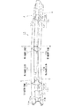
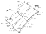
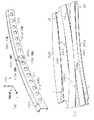
自動車の車体5の上部において、車幅方向両端部には、車体前後方向に沿って左右一対のルーフサイドレール6が配置されている。ルーフサイドレール6の前端部には、フロントルーフレール7Aが配置されている。ルーフサイドレール6の後端部には、リヤルーフレール7Bが配置されている。ルーフサイドレール6の前端部には、フロントピラー10の上端部が連結されている。ルーフサイドレール6の後端部には、リヤピラー8の上端部が連結されており、ルーフサイドレール6の車両前後方向中間部には、センタピラー9の上端部が連結されている。図1にはフロントピラー10の軸線方向(長手方向)から見た中央部の断面形状(B−B断面)が示されている。
A pair of left and right roof side rails 6 are arranged along the longitudinal direction of the vehicle body at both ends in the vehicle width direction at the upper part of the vehicle body 5 of the automobile. A front roof rail 7 </ b> A is disposed at the front end of the
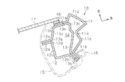
図2に示すように、フロントピラー10は、車体外側部を構成するピラーアウタパネル11と、フロントピラー10の車体内側部を構成するピラーインナパネル12と、ピラーアウタパネル11・ピラーインナパネル12間に介在して配置されたフロントピラー構成部材13を備える。
As shown in FIG. 2, the
ピラーアウタパネル11は、前後両部に第1フランジ部11a,第2フランジ部11bを有し、中間部11cが車室外側方に断面突形(本実施形態では、コ字状)に突出して形成されている。本実施形態では、中間部11cはコ字状に突出して形成されているが、コ字状に限定されるものではない。又、中間部11cから後側壁11dには、外側方へ向けて段部11eが形成されている。
The pillar
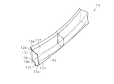
図2、図3に示すようにフロントピラー構成部材13は、一枚の金属板から形成され、前後両部に第3フランジ部13a,第4フランジ部13bを有し、第3フランジ部13aと第4フランジ部13b間は、第1曲面部13f、第2曲面部13d、中間部13c、第4曲面部13m、及び第3曲面部13jを備えている。すなわち、第3フランジ部13aと第4フランジ部とは合掌状に当接された状態でスポット溶接されることにより連結されて、第3フランジ部13aと第4フランジ部13b間は、第1曲面部13f、第2曲面部13d、中間部13c、第4曲面部13m、及び第3曲面部13jにより図1、図2に示すように閉断面部14を構成する。前記閉断面部14は、閉断面構造に相当する。
As shown in FIGS. 2 and 3, the front
詳説すると、第3フランジ部13aには屈曲部13gを介して前方へ延びる第1曲面部13fが連結されている。第1曲面部13fの前方を向く面は、図3に示すように長手方向において凹面に形成されている。
More specifically, a first
第1曲面部13fには、屈曲部13eを介して外側方ヘ向けて延びる第2曲面部13dが連結されている。図1に示すように第2曲面部13dはウインドシールドガラス17を接着する接着面13sと、ピラーアウタパネル11の第1フランジ部11aがシリーズ溶接される連結面13rとを有する。接着面13sには、ウインドシールドガラス17が接着剤18にて接着されている。接着面13sは、ウインドシールドガラス17を支持する支持面に相当する。
A second
第2曲面部13dは前方を向くように配置されている。第2曲面部13dは、フロントピラー10の長手方向において、前方へ膨らむ凸面を有するように形成されている。
一方、第4フランジ部13bには屈曲部13iを介して外側方へ延びる第3曲面部13jが連結して形成されている。第3曲面部13jは、長手方向において、前記第2曲面部13dと平行となる凹面を有する。
The second
On the other hand, the
第3曲面部13jには、屈曲部13kを介して前方へ延びる第4曲面部13mが連結されている。第4曲面部13mは、長手方向において凸面を有する。
第2曲面部13dと第4曲面部13m間は、車室外側方に突出した中間部13cが連結されている。中間部13cは、フロントピラー構成部材13の両端部では、図1、図3に示すように長手方向に帯状に延びる面取り部13p、該面取り部13pを第2曲面部13d、第4曲面部13mにそれぞれ連結する連結部13q,13tとを備え、図1、図3に示すように連結部13q,13t、面取り部13pとにより断面コ字状をなすように膨出して形成されている。面取り部13pは平坦面とされている。なお、図3において、フロントピラー構成部材13のA−A線、C−C線での断面図は、二点鎖線で示されている。
The third
Between the second
前記膨出した部位は膨出部に相当する。なお、膨出部の断面形状はコ字状に限定されるものではなく、断面台形状でもよく、又、全体が断面円弧状であってもよい。
又、中間部13cは、フロントピラー構成部材13の中央部(図3において、B−B線の付近の領域)では、連結部13qが省略されて面取り部13pが第2曲面部13dに対して連結されるとともに、第4曲面部13mを介して第4曲面部13mに連結されている。なお、連結部13qを省略せずに、長手方向の両端部の連結部13qよりも膨出量(高さ)を少なくしてもよい。
The bulged portion corresponds to a bulged portion. In addition, the cross-sectional shape of the bulging portion is not limited to the U-shape, and may be a trapezoidal cross-sectional shape or may be a circular arc shape as a whole.
Further, the
又、面取り部13pは、フロントピラー構成部材13の中央部から両端部に行くほど、第3フランジ部13a、第4フランジ部13bからの離間距離が長くなるように前記膨出した部位(膨出部)に配置されている。
Further, the chamfered
ピラーアウタパネル11は、第1フランジ部11aが、フロントピラー構成部材13の中間部13cにおいて、フロントピラー構成部材13の前方を向く第2曲面部13dの連結面13rに対しシリーズ溶接されている。
In the pillar
フロントピラー構成部材13の第3フランジ部13aは、図1に示すように中間部13cから、第2曲面部13d、屈曲部13e、第1曲面部13f及び屈曲部13gを介して、車室内側方に位置している。又、第4フランジ部13bは、図1に示すように中間部13cから、第4曲面部13m、屈曲部13k、第3曲面部13j、及び屈曲部13iを介して車室内側方に位置している。
As shown in FIG. 1, the
ピラーインナパネル12は、前部の第5フランジ部12aと、中間部12c及び後部の第6フランジ部12bとを備えている。第5フランジ部12aは、図1に示すように略L字状に屈曲され、フロントピラー構成部材13の第3曲面部13jに対してシリーズ溶接されている。なお、このシリーズ溶接は、ピラーアウタパネル11の第1フランジ部11aとフロントピラー構成部材13の連結面13rとのシリーズ溶接と同時に行われる。第6フランジ部12bは、ピラーアウタパネル11の第2フランジ部11bに対してスポット溶接されている。
The pillar
本実施形態では、フロントピラー構成部材13の屈曲部13e、第1曲面部13f、屈曲部13gを介して車室内側方に第3フランジ部13aが突出し、中間部13cから、第4曲面部13m、屈曲部13k、第3曲面部13j、及び屈曲部13iを介して第4フランジ部13bが車室内側方に第3フランジ部13aが突出している。第3フランジ部13aと第4フランジ部13bとがスポット溶接されている。
In the present embodiment, the
すなわち、第3フランジ部13aと第4フランジ部13bのスポット溶接部位を、ピラーガーニッシュ15の前端(ウインドシールドガラス17に近位に位置する端)に位置させないように、ピラーガーニッシュ15の前端から離間した位置において、ピラーガーニッシュ15にて覆われるようにしている。
That is, the spot welded portion of the
因みに従来は、図18に示すようにフランジ部120a,130a(及び110a)のスポット溶接部位は、ピラーガーニッシュ150の前端(ウインドシールドガラス170に近位に位置する端)に位置させて、ピラーガーニッシュ15にて覆われるようにしている。
Incidentally, conventionally, as shown in FIG. 18, the spot welded portions of the
このことにより、本実施形態では、閉断面部14が、図18に示す従来の閉断面部140よりも断面積を大きくすることができる。このため、ピラーアウタパネル11の中間部11cの前後方向の幅を従来(例えば、図18参照)よりも短くしても、すなわち、フロントピラー10の前後方向の長さを短くしてもフロントピラー10に求められる(必要な)剛性を得ることができる。
Thereby, in this embodiment, the closed
ピラーインナパネル12の車室内方にはピラーガーニッシュ15が配置されており、フロントピラー10の車室内側部が被覆されている。すなわち、図1に示すように、第3フランジ部13a、第4フランジ部13bは、ピラーガーニッシュ15により、覆われている。図1に示すように、第2フランジ部11b,第6フランジ部12bには、オープニングウエザストリップ16が取付けられており、図示しないフロントサイドドアに密着可能である。
A
(製造方法)
ここで、フロントピラー構成部材13は、1枚の金属板により略角パイプ状に構成され、凹面を有する第1曲面部13f、凸面を有する第2曲面部13d、中間部13c、凹面を有する第3曲面部13j、及び凸面を有する第4曲面部13mを有するという新規な構成であるため、フロントピラー構成部材13の製造方法について説明する。
(Production method)
Here, the front
(1.比較例の製造方法の検討)
まず、比較例として1枚の金属板から角パイプ状にフロントピラー構成部材を形成する場合に、一般的に考えられる製造方法を図13〜15を参照して説明する。
(1. Examination of manufacturing method of comparative example)
First, the manufacturing method generally considered when forming a front pillar component member in the shape of a square pipe from one metal plate as a comparative example will be described with reference to FIGS.
図13は、比較例のフロントピラー構成部材を使用する場合のフロントピラーの構造を示す。図13においてはピラーアウタパネル11の各部、ピラーインナパネル12の各部、ピラーガーニッシュ15、オープニングウエザストリップ16、及びウインドシールドガラス17は既に説明した本実施形態の構成と同じであるため、同一符号を付す。
FIG. 13 shows the structure of the front pillar when the front pillar component of the comparative example is used. In FIG. 13, each part of the pillar
又、比較例のフロントピラー構成部材については、200の符号を付し、フロントピラー構成部材200の各部において、フロントピラー構成部材13の各部に相当する構成については、フロントピラー構成部材13の各部に付した英小文字を200に付す。
Further, the front pillar constituent member of the comparative example is denoted by
図13に示すように、フロントピラー構成部材200は、前部のフランジ部200a、曲面部200f、屈曲部200e、前方を向く曲面部200d、外側方を向く曲面部200m、屈曲部200k、曲面部200j、及び後部のフランジ部200bを備えて、四角パイプ状に折曲げ形成され、閉断面部14を有する。
As shown in FIG. 13, the
曲面部200fは、フロントピラー構成部材200の長手方向において凹面を有する。曲面部200dは、フロントピラー構成部材200の長手方向において凸面を有する。曲面部200jは、フロントピラー構成部材200の長手方向において、曲面部200dの凸面と平行な凹面を有する。曲面部200mは、フロントピラー構成部材200の長手方向において凸面を有する。
The curved surface portion 200 f has a concave surface in the longitudinal direction of the front
上記のように、比較例のフロントピラー構成部材200においては、フロントピラー構成部材13の凹面、凸面の前後位置、及び車両外側に対する位置の対応関係は同様にされている。
As described above, in the front
又、曲面部200dは、ウインドシールドガラス17が接着剤18により接着される接着面200s及び第1フランジ部11aをシリーズ溶接する連結面200rを備える。図14(a)において、曲面部200mには長手方向に複数のスポット溶接用の逃し孔210が形成され、逃し孔210を介して、図示しない溶接ガンが閉断面部14内の空間に挿入されて、互いに重ね合わされたフランジ部200a,200bがスポット溶接される。
The
上記のように構成されたフロントピラー構成部材200を一枚の金属板250で形成する場合、図15(a)に示すように、凹面を有するようにフランジ部200aを屈曲部200eでプレスで屈曲し、図15(b)、図15(c)に示すように曲面部200mと曲面部200d間の屈曲部で、曲面部200dが凸面を有するようにプレスで屈曲する形成する必要がある。又、図15(c)、図15(d)に示すように屈曲部200kで図の左側の部位をプレスで屈曲するとともに、曲面部200mは凸面を有するように形成する。又、図15(d)、図15(e)に示すように曲面部200jとフランジ部200b間の屈曲部にて曲面部200jに凹面を有し、フランジ部200bに凹面を有するようにプレスで屈曲形成する必要がある。
When the
しかし、これらの屈曲部で互いに隣接する曲面部に凹面、凸面を形成する場合、当該屈曲部では、伸び、縮みが発生し、屈曲部の曲げ精度の維持が困難となり、フロントピラー構成部材200の精度の確保が難しい。 However, in the case where concave and convex surfaces are formed on the curved surface portions adjacent to each other at these bent portions, the bent portions are elongated and contracted, and it becomes difficult to maintain the bending accuracy of the bent portions. It is difficult to ensure accuracy.
具体的に説明すると、図14(b)は、図14(a)におけるフロントピラー構成部材200を平たくすべく展開した場合の仮想的な説明図である。
同図に示すように、フロントピラー構成部材200を展開した状態では、フランジ部200bと曲面部200jの長手方向の各端部間では、D1,D2で指し示すハッチング部分で示すように大きな重なりが生じ、図15で説明したプレス成形時には大きな肉不足による伸びを伴ってフランジ部200bが形成されることになる。
More specifically, FIG. 14B is a virtual explanatory diagram when the
As shown in the figure, when the front
図14において、Eで指し示すハッチング部分で、すなわち、曲面部200jと曲面部200mの長手方向の中央部間では小さなスキが生じ、図14で説明したプレス成形時には小さな肉余りによる縮みを同部位では生ずることになる。図14において、F1,F2で指し示すハッチング部分では、すなわち、曲面部200mと曲面部200dの長手方向の各端部間では、大きなスキが生じ、図14で説明したプレス成形時には大きな肉余りによる縮みを同部位では生ずることになる。又、図14において、G1,G2で指し示すハッチング部分では、すなわち、曲面部200dとフランジ部200aの長手方向の各端部間では、小さなスキが生じ、図14で説明したプレス成形時には小さな肉余りによる縮みを同部位では生ずることになる。このように比較例では、プレス成形時に曲面部間、及びフランジ部と曲面部間に伸び縮みが生じ、この製造方法では実際にフロントピラー構成部材200の製造は極めて難しい。
In FIG. 14, a small gap occurs in the hatched portion indicated by E, that is, between the central portion in the longitudinal direction of the
(2.フロントピラー構成部材の製造方法)
次に、本実施形態のフロントピラー構成部材13の製造方法の原理を図4、図5を参照して説明する。
(2. Manufacturing method of front pillar component)
Next, the principle of the method for manufacturing the front
(2.1.原理)
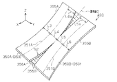
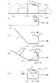
図4に示すように一枚の平板状の金属板350を長手方向(X方向)に延びる円弧状の曲線351を境に上方(Z方向)へ曲げると、図5に示すように、金属板350に伸び縮みがない、3次元形状面を有する板部352、353が形成される。
(2.1. Principle)
When a single
図5において、下部に位置する板部352は、図5の側面視方向(図5の反Y方向)から見た場合、長手方向の両端が中央部よりも上方(Z方向側)に変位して下面が凸面を有する曲面(3次元形状面)を有する。 In FIG. 5, when viewed from the side view direction (the anti-Y direction in FIG. 5) of FIG. 5, the plate portion 352 located in the lower portion is displaced at both ends in the longitudinal direction above the center portion (Z direction side). The lower surface has a curved surface (a three-dimensional shape surface) having a convex surface.
又、板部352に対して上方へ立設するように曲げて形成された板部353は、図5の平面視方向(反Z方向)から見た場合、長手方向の両端が中央部よりも図5において反Y方向側に変位して反Y方向に向く面が凹面となった曲面(3次元形状面)を有する。この場合、金属板(すなわち、材料)に伸び縮みが無い場合には、板部352,353の曲面の曲率半径は同じになる。
Further, the
ここで、金属板350の長手方向に沿った両側部355,356を、曲線351と平行となるように形成しておくと、図5に示すように、板部352は長手方向に沿って同一幅を有したものとなる。同様に、板部353は長手方向に沿って同一幅を有したものとなる。従って、図4に示すように、側部355は長手方向の中央部が、両端部よりもY方向に凹む円弧状の凹部となる。側部356は、長手方向の中央部が、両端部よりもY方向に突出した円弧状の凸部となる。
Here, if both
図4において、L1は、曲線351と反Y方向に位置する側部355の幅を示し、L2は曲線351とY方向に位置する側部356の幅を示す。なお、L1とL2は同じ値でもよく、又は同じ値でなくてもよい。
In FIG. 4, L1 indicates the width of the
上記の原理を利用し、さらに、平板の金属板を角パイプ状に形成する原理を図6〜9を参照して説明する。
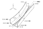
金属板400は、一対の金属板350を連結して形成した形状であり、具体的には、一対の金属板350を互いに逆方向に向き合わせて、側部356の長手方向の中央部で連結した形状に形成され、仮想の基準線Oを中心線として線対称となる形状を有する。前記金属板400は、プレス成形等により形成される。
The principle of forming a flat metal plate into a square pipe shape using the above principle will be described with reference to FIGS.
The
なお、前記基準線Oは、図6では説明の便宜上曲げて描いているが、実際は直線である。
図6、図7では、説明の便宜上、図4、図5で説明した構成に相当する各部には、図4で使用した同じ符号に、それぞれA,Bの符号を付加する。又、図6、図7において、側部356A,356Bの両端間のハッチング部分N1,N2においては、ここでの説明では便宜上、金属板の部分はないものとして理解されたい。
The reference line O is bent for convenience of explanation in FIG. 6, but is actually a straight line.
In FIGS. 6 and 7, for convenience of explanation, A and B symbols are added to the same symbols used in FIG. 4 to the respective parts corresponding to the configurations explained in FIGS. 6 and 7, it should be understood that the hatched portions N1 and N2 between both ends of the
側部355Aは、長手方向の中央部が両端部よりもY方向に凹む円弧状の凹部を有する。又、側部355Bは、長手方向の中央部が両端部よりも反Y方向に凹む円弧状の凹部を有する。金属板部350Aの長手方向に沿った両側部355A,356Aは、曲線351Aと平行となるように形成されている。金属板部350Bの長手方向に沿った両側部355B,356Bは、曲線351Bと平行となるように形成されている。曲線351A,351Bの曲率半径は、同一にされている。
The
図6において、L3は、曲線351Aと反Y方向に位置する側部355Aの幅を示し、L4は曲線351AとY方向に位置する側部356Aの幅を示す。L3とL4は同じ値でもよく、又は同じ値でなくてもよい。L5は、曲線351Bと反Y方向に位置する側部356Bの幅を示し、L6は曲線351BとY方向に位置する側部355Bの幅を示す。L5とL6は同じ値でもよく、又は同じ値でなくてもよい。幅L3と幅L5は等しいか略等しいことが好ましい。又、幅L4と幅L6は等しいか、或いは略等しいことが好ましい。
In FIG. 6, L3 indicates the width of the
上記のように形成された金属板400の曲線351A,351B上で金型を使用して、プレス成形し、図7に示すように板部353A,353Bを板部352A、352Bからそれぞれ立設する。なお、曲線351A,351B上を破線状にレーザカットを行うことにより、金型を使用しないで図7に示すように板部353A,353Bを板部352A、352Bからそれぞれ立設することも可能である。
Press molding is performed on the
図7に示す状態では、板部352A、352Bは長手方向の中央部が、両端部よりも反Z方向に膨らむ凸面を有する。板部353Aは長手方向の中央部が、両端部よりもY方向に向かう凹面を有する。板部353Bは長手方向中央部が、両端部よりも反Y方向に向かう凹面を有する。板部352Aと板部353A、及び、板部352Bと板部353Bとはそれぞれ断面L字状に配置される。
In the state shown in FIG. 7, the plate portions 352 </ b> A and 352 </ b> B have a convex surface in which the center portion in the longitudinal direction swells in the anti-Z direction rather than both end portions. The
ここで図7の状態において、金属板400に伸び縮みが無い場合には、板部352A,352B,353A,353Bの曲面の曲率半径は同じになる。
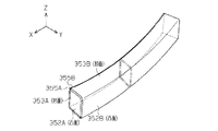
次に、図8に示すように金属板部350Bを基準線O上の連結箇所にてZ方向へ略90°屈曲し、側部355Aと側部355B同士が互いに縁部にて当接するように配置する。
Here, in the state of FIG. 7, when the
Next, as shown in FIG. 8, the
この状態で、金属板400を、閉断面部を備える角パイプ状にすることができる。そして、図8に示すように、図7の状態から金属板400を基準線O上の連結箇所にてZ方向へ略90°屈曲するだけであることから、屈曲した部分以外には金属板400に伸び縮みが発生しないため、板部352A,352B,353A,353Bの曲面の曲率半径は同じである。従って、側部355A,355Bの長手方向に延びる縁部は互いに合致して当接することが可能となる。
In this state, the
(2.2 フロントピラー構成部材13の製造方法)
次に、フロントピラー構成部材13の具体的な製造方法を前記図7〜11を参照して説明する。
(2.2 Manufacturing Method of Front Pillar Component 13)
Next, a specific method for manufacturing the front
まず、金属板400について説明する。金属板400は、上記の原理の説明では、金属板部350A,350Bを互いに、長手方向の中央部で直接連結した構成としたが、実際には図9に示すように金属板部350A、350Bが、所定幅Hを有して長手方向に延びた中間領域Tを介して連結されている。中間領域Tの中心線は、金属板400の中心線である基準線Oと一致する。前記所定幅Hについては後述する。
First, the
又、金属板400は、図9に示すように、側部355A,355Bにそれぞれ前記第3フランジ部13a、及び第4フランジ部13bとなる部分(図9において、二点鎖線で図示した部分)を有するようにプレス成形等により形成する。従って、なお、前記原理での説明における側部356A、356Bは省略されている。
Further, as shown in FIG. 9, the
ここで、側部355A,355Bにそれぞれ第3フランジ部13a、及び第4フランジ部13bとなる部分(図6において、二点鎖線で図示した部分)を延出した部分の側縁部は、それぞれ長手方向に延びる第1側縁部401と第2側縁部402に相当し、同じ円弧状の凹部をそれぞれ備えている。
Here, the side edge portions of the portions extending from the
第1側縁部401の凹部は、後述する曲線351Aと平行に形成されている。第2側縁部402の凹部は、後述する曲線351Bと平行に形成されている。
金属板400の基準線Oから第1側縁部401までが第1領域403に相当し、基準線Oから第2側縁部402迄が第2領域404に相当する。
The concave portion of the first
From the reference line O to the
ここで、第1領域403では、第1側縁部401の凹部に平行な曲線351Aが設定されており、第2領域404では第2側縁部402の凹部に平行な曲線351Bが設定されている。
Here, in the
中間領域Tの曲線351A側の境界線は、曲線351Aと平行であり、曲線351AとL7の幅分離間している。曲線351Aは、第1折曲げ線に相当する。中間領域Tの曲線351B側の境界線は、曲線351Bと平行であり、曲線351BとL8の幅分離間している。曲線351Bは、第2折曲げ線に相当する。従って、中間領域Tの所定幅Hは、金属板400の長手方向とは直交する幅から、L3+L7+L8+L6の合計分を減算した値である。そして、所定幅Hは、長手方向の中央部が最小値となり、両端部に行くほど徐々に長くなる値を有する。
The boundary line on the
前述した幅L7の領域は、幅L3を有する領域(後に第1側板部としての板部353A)よりも基準線Oに近位の第1近位領域に相当する。前述した幅L8の領域は、幅L6を有する領域(後に第2側板部としての板部353Bとなる領域)よりも基準線Oに近位の第2近位領域に相当する。
The region having the width L7 described above corresponds to a first proximal region closer to the reference line O than a region having a width L3 (later
なお、幅L7は、前記原理で説明した幅L4に相当し、幅L8は幅L5に相当する。従って、L3とL7は同じ値でもよく、又は同じ値でなくてもよい。L8とL6は同じ値でもよく、又は同じ値でなくてもよい。幅L3と幅L8は等しいか略等しいことが好ましく、幅L7と幅L6は等しいか、或いは略等しいことが好ましい。 上記のように形成された金属板400の中間領域Tに対して、図11(a)に示すように、上下一対の金型KA1,KA2により、長手方向に亘って、膨らみ部13wを形成する。
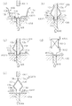
The width L7 corresponds to the width L4 described in the above principle, and the width L8 corresponds to the width L5. Therefore, L3 and L7 may be the same value or not the same value. L8 and L6 may be the same value or not the same value. The width L3 and the width L8 are preferably equal or approximately equal, and the width L7 and the width L6 are preferably equal or approximately equal. With respect to the intermediate region T of the
次に、図11(b)に示すように、金属板400をボルスタKA5上に固定されたダイKA4上に載置し、この状態で図示しないラムにより上下動自在のパンチKA3を下死点まで移動させることにより、図11(c)に示すようにプレス成形し、板部353A,353Bを板部352A、352Bからそれぞれ立設する。又、同時に、図11(c)に示すように第3フランジ部13a、及び第4フランジ部13bとなる部分を折曲げ形成する。なお、ダイKA4及びボルスタKA5には、金属板400の膨らみ部13wの下面に図11(b)に示すように当接部材KA6が当接されている。当接部材KA6の上面は、膨らみ部13wの下面の谷面に嵌合するように断面三角形状に形成されている。前記当接部材KA6はクッション圧を付与するクッションピンCPに支持されて上下動自在にされており、前記パンチKA3が下死点に移動した際、図11(c)に示す位置まで下動する。
Next, as shown in FIG. 11 (b), the
このようにして図11(c)に示すように、金属板400に第4フランジ部13b、第3曲面部13j、屈曲部13k,第4曲面部13m、連結部13t、連結部13q、第2曲面部13d、第1曲面部13f、第3フランジ部13aに相当する領域が区画される。なお、このとき、連結部13t及び連結部13qに相当する領域は、金属板400の長手方向の両端部では、パンチKA3及びダイKA4により長手方向の両端部に行くほど、長手方向と直交する方向の長さが長くなるように、すなわち、後に膨出部が形成されるときに、両端部に行くほど膨出量が増加するように形成される。
Thus, as shown in FIG. 11 (c), the
本実施形態では、図11(c)に示すように、第4曲面部13m、第2曲面部13dが共通の平面(図11(c)では水平面)に含まれるように形成したが、第4曲面部13m、第2曲面部13dは、必ずしも共通の平面に含まれることは限定されるものではない。例えば前記水平面に対して第4曲面部13m、第2曲面部13dが傾いていても良い。
In the present embodiment, as shown in FIG. 11C, the fourth
なお、原理でも説明したように曲線351A,351B上を破線状にレーザカットを行うことにより、金型を使用しないで板部353A,353Bを板部352A、352Bからそれぞれ立設してもよい。
As described in the principle, the
次に、図12(a)に示すように、金型KA8上に前記金属板400を載置する。すなわち、金型KA8上面には互いに所定距離離間した一対の平板状の金型KA10が固定されており、金型KA10間に、金属板400の連結部13t,連結部13qが挿入される。前記所定距離は、図12(a)に示すように、連結部13t及び連結部13qが挿入され、かつ、第4曲面部13m,第2曲面部13dが、各金型KA10上に載置できる長さに設定されている。又、金型KA8には、図12(a)に示すように金属板400の膨らみ部13wの下面に図11(b)に示すように当接部材KA9が当接されている。前記当接部材KA9はクッション圧を付与する図示しないクッションピンに支持されて上下動自在にされており、後述する芯金KA11が下死点に移動した際、図12(b)に示す位置まで下動する。前記当接部材KA9の膨らみ部13wに当接する上端面は平面を有する。
Next, as shown in FIG. 12A, the
次に、図12(b)に示すように、前記当接部材KA9と対向するように配置され、図示しないラムにより上下動自在に構成された芯金KA11を下死点まで作動させて、膨らみ部13wを長手方向に亘ってプレス成形した後、該膨らみ部13wを潰すようにしてパンチ形成し、長手方向の中央部が帯状の面取り部13pを有するように形成する。前記芯金KA11の押圧により、金属板400の第3フランジ部13a,第4フランジ部13bは芯金KA11に当接するまで変形する。
Next, as shown in FIG. 12 (b), the metal core KA11, which is arranged so as to face the contact member KA9 and is movable up and down by a ram (not shown), is actuated to the bottom dead center, and then bulges. After the
この後、図12(c)に示すように、前記当接部材KA9、芯金KA11を若干上動させる。
なお、金属板400の両端部は、第4フランジ部13b、第3曲面部13j、屈曲部13k、第4曲面部13m、第2曲面部13d、第1曲面部13f、第3フランジ部13aを備えていない場合がある。この場合は、金属板400の両端部に対しては、図12(d)に示すように、上下動自在に図示しないラムに連結固定された部材KA14に対してバネ部材KA13を介して連結されたパンチKA12が下死点まで下動する。その後、図12(d)に示すように前記当接部材KA9、芯金KA11を若干上動させる。
Thereafter, as shown in FIG. 12C, the contact member KA9 and the cored bar KA11 are slightly moved up.
It should be noted that both ends of the
その後、図12(c)の状態から、図12(e)に示すように、芯金KA11を金属板400から抜き取る。抜き取りされた後、金属板400の第3フランジ部13a,第4フランジ部13bは、金属板400の弾性変形により、互いに当接した状態となる。
Thereafter, from the state of FIG. 12C, the cored bar KA11 is extracted from the
すなわち、金属板400は、その膨らみ部13wが形成されていた領域が弾性により形状を回復しようとし、第3フランジ部13a,第4フランジ部13bとの当接した状態の閉断面部14を形成した状態を確実に維持することが可能となる。
That is, the
この結果、フロントピラー構成部材13は、図1、図3に示すように長手方向に帯状に延びる面取り部13pと、該面取り部13pを第2曲面部13d、第4曲面部13mにそれぞれ連結する連結部13q,13tとを備えるように形成される。
すなわち、図1、図3に示すように連結部13q,13t、面取り部13pとにより断面コ字状をなすように膨出して形成される。又、フロントピラー構成部材13の中央部では、連結部13qが省略されて面取り部13pが第2曲面部13dに対して連結されるとともに、第4曲面部13mを介して第4曲面部13mに連結されるように、パンチKA3,ダイKA4、芯金KA11等により形成される。なお、連結部13qを省略せずに、長手方向の両端部の連結部13qよりも膨出量(高さ)を少なくする場合には、パンチKA3,ダイKA4の加工面の形状を変更すればよい。
As a result, as shown in FIGS. 1 and 3, the front
That is, as shown in FIG. 1 and FIG. 3, it is formed to bulge so as to form a U-shaped cross section by the connecting
なお、膨らみ部13wを形成しない場合には、図11(a)の工程を省略し、図11(b)に示す当接部材KA6の上面を平面にすればよい。
第1実施形態によれば、下記の特徴がある。
In the case where the bulging
The first embodiment has the following features.
(1) 本実施形態のフロントピラーの構造は、フロントピラー構成部材13の第3フランジ部13aをピラーガーニッシュ15の前後方向の中間部と相対するように配置し、フロントピラー構成部材13の第3フランジ部13a、第4フランジ部13b間に、ウインドシールドガラス17を支持する接着面13s(支持面)を備えている。このため、フロントピラー10の前後方向の長さを短くでき、すなわち、細幅化でき、この結果、運転者からのフロントピラーを介しての車外の視界を良好にして悪化させることがない。
(1) The structure of the front pillar of the present embodiment is such that the
(2)本実施形態のフロントピラーの構造は、閉断面部14(閉断面構造)は、第3フランジ部13a、第4フランジ部13bが合掌状に連結され、第3フランジ部13aから前方へ延びる凹面を備える第1曲面部13fが形成され、第1曲面部13fに連結されて接着面13s(支持面)を含み凸面を備える第2曲面部13dが形成されている。又、第4フランジ部13bから外側方へ延びる凹面を備える第3曲面部13jが形成され、第3曲面部13jから前方へ屈曲されて凸面を備える第4曲面部13mが形成され、フロントピラー構成部材13の中間部13cが第2曲面部13dと第4曲面部13m間を連結する。
(2) The structure of the front pillar of the present embodiment is such that the closed cross-section portion 14 (closed cross-section structure) is such that the
この結果、本実施形態によれば、第3フランジ部13a、第4フランジ部13b間に形成された第1曲面部13f、第2曲面部13d、第3曲面部13j及び第4曲面部13mにて閉断面構造が形成されることにより、上記(1)の効果を容易に実験することができる。
As a result, according to the present embodiment, the first
(3) 本実施形態のフロントピラーの構造は、フロントピラー構成部材13の中間部13cは、面取り部13pを含み、該面取り部13pは、フロントピラー構成部材13の長手方向の中央部から両端部に行くほど第3フランジ部13a、第4フランジ部13bからの離間距離が長くなるように形成された膨出した部位に配置されている。この結果、本実施形態では、フロントピラー構成部材13の長手方向の両端部に膨出した部位に面取り部13pが形成されていることにより、フロントピラー構成部材13の両端部の強度を挙げることができる。
(3) In the structure of the front pillar of the present embodiment, the
(4) 本実施形態のフロントピラー構成部材13の製造方法は、第1工程として、金属板400に対して、長手方向に延びる第1側縁部401と第2側縁部402が同長手方向に延びる仮想の基準線Oを中心線とし、かつ第1側縁部401と第2側縁部402が同じ円弧状の凹部をそれぞれ備えるように形成する。
(4) In the manufacturing method of the front
第2工程として、金属板400の基準線Oから第1側縁部401までの第1領域403では、第1側縁部401の円弧状の曲率半径を有する凹状の曲線351A(第1折曲げ線)上で曲げて、基準線Oに近位の第1近位領域から板部353A(第1側板部)を立設する。さらに、基準線Oから第2側縁部402までの第2領域404では、第2側縁部402の円弧状の曲率半径を有する凹状の曲線351B(第2折曲げ線)上で曲げて、基準線Oに近位の第2近位領域から板部353B(第2側板部)を第1側板部と同方向に立設する。
As a second step, in the
又、第3工程として、第1、第2近位領域内の一部にそれぞれ含まれる領域であって、基準線Oを中心線にする長手方向に延びる中間領域Tに対して、板部353A,板部353Bの立設方向とは反対方向へ押圧して長手方向の両端部に行くほど、膨出量が増加する膨出部を形成し、かつ、第1側縁部401、第2側縁部402に設けられた第4フランジ部13b、第3フランジ部13a同士で当接させる。この結果、金属板400に対してプレス成形をする場合、伸び及び縮みを抑制したフロントピラー構成部材13を得ることができる。
Further, as a third step, the
(5) 本実施形態のフロントピラー構成部材13の製造方法は、第3工程において、中間領域Tにおいて、面取り部13pを形成する。この結果、中間領域Tに面取り部13pを有したフロントピラー構成部材13を得ることができる。
(5) The manufacturing method of the front
(6) 本実施形態のフロントピラー構成部材13の製造方法は、第3工程において、中間領域Tに、板部353A,板部353Bの立設方向と同方向の膨らむ膨らみ部13wを形成し、該膨らみ部13wを押圧して潰すことにより、第1側縁部401、第2側縁部402に形成されたフランジ同士を弾性的に当接させる。この結果、膨らみ部13wを形成して、該膨らみ部を押圧して潰して変形することにより、フロントピラー構成部材13は、該膨らみ部13wの変形により、第1側縁部401、第2側縁部402に形成されたフランジ部同士を弾性的に当接させることができる。
(6) In the third step, the manufacturing method of the front
(第2実施形態)
次に第2実施形態を図16を参照して説明する。
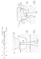
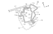
なお、第1実施形態の構成と同一構成又は相当する構成については同一部号を付し、異なる構成を中心に説明する。図16は、前記第1実施形態において、フロントピラー10の軸線方向(長手方向)から見た中央部のB−B線断面図に相当するものである。
(Second Embodiment)
Next, a second embodiment will be described with reference to FIG.
In addition, about the same structure as the structure of 1st Embodiment, or the structure corresponded, the same part number is attached | subjected and it demonstrates centering on a different structure. FIG. 16 corresponds to a cross-sectional view taken along the line B-B of the central portion viewed from the axial direction (longitudinal direction) of the
フロントピラー構成部材13は、前後両部に第3フランジ部13a,第4フランジ部13bを有し、中間部13cが車室外側方に突出して断面突形に形成されている。そして、ピラーアウタパネル11は、第1フランジ部11aが、フロントピラー構成部材13の中間部13cにおいて、前方を向く面13nに対しスポット溶接されている。フロントピラー構成部材13の第3フランジ部13aは、図16に示すように中間部13cから、溶接対象にしている面13n、屈曲部13e、延出部13o及び屈曲部13gを介して、車室内側方に位置している。
The front
ピラーインナパネル12において、第5フランジ部12a,第6フランジ部12bの中間部12cは、車室内側方へ突出するように断面突形に形成されている。本実施形態では、中間部12cは山形に形成されている。
In the pillar
フロントピラー構成部材13の前部の第3フランジ部13aは、ピラーインナパネル12の前部の第5フランジ部12aに対してスポット溶接されている。ピラーアウタパネル11、ピラーインナパネル12、及びフロントピラー構成部材13の後部の第2フランジ部11b,第6フランジ部12b,第4フランジ部13bは重ね合わされてスポット溶接により接合されている。
The
ピラーアウタパネル11と、フロントピラー構成部材13において、屈曲部13eからフランジ13迄の部位と、ピラーインナパネル12とにより、閉断面部14が形成されている。
In the pillar
本実施形態は、屈曲部13e、延出部13o、屈曲部13gを介して車室内側方に第3フランジ部13aが突出し、同第3フランジ部13aと、断面突形に形成されたピラーインナパネル12の中間部12cを介して車室内側方へ突出した第5フランジ部12aとがスポット溶接されている。すなわち、第5フランジ部12a,第3フランジ部13aのスポット溶接部位を、ピラーガーニッシュ15の前端(ウインドシールドガラス17に近位に位置する端)に位置させないように、ピラーガーニッシュ15の前端から離間した位置において、ピラーガーニッシュ15にて覆われるようにしている。
In the present embodiment, a
因みに従来は、図18に示すようにフランジ部120a,130a(及び110a)のスポット溶接部位は、ピラーガーニッシュ150の前端(ウインドシールドガラス170に近位に位置する端)に位置させて、ピラーガーニッシュ15にて覆われるようにしている。
Incidentally, conventionally, as shown in FIG. 18, the spot welded portions of the
このことにより、本実施形態では、閉断面部14が、図18に示す従来の閉断面部140よりも断面積を大きくすることができる。このため、ピラーアウタパネル11の中間部11cの前後方向の幅を従来(例えば、図18参照)よりも短くしても、すなわち、フロントピラー10の前後方向の長さを短くしてもフロントピラー10に求められる(必要な)剛性を得ることができる。
Thereby, in this embodiment, the cross-sectional area of the
ピラーインナパネル12の車室内方にはピラーガーニッシュ15が配置されており、フロントピラー10の車室内側部が被覆されている。すなわち、図16に示すように、第5フランジ部12a,第3フランジ部13aは、ピラーガーニッシュ15により、覆われている。第2フランジ部11b,第6フランジ部12b,第4フランジ部13bには、オープニングウエザストリップ16が取付けられており、図示しないフロントサイドドアに密着可能である。又、ピラーアウタパネル11の第1フランジ部11aには、ウインドシールドガラス17が接着剤18にて接着されている。本実施形態では、ウインドシールドガラス17が接着剤18にて接着されている第1フランジ部11aを背面から支える面13nは、ウインドシールドガラス17を支持する支持面に相当する。
A
さて、上記のように構成されている、フロントピラーの製造方法について説明する。
まず、第1工程として、フロントピラー構成部材13の中間部13cにおいて、面13nに対して、ピラーアウタパネル11の前部の第1フランジ部11aをスポット溶接する。この場合、図16において、フロントピラー構成部材13において中間部13cの左側方は開口し、中間部13cは車室外側方へ突出しているため、スポット溶接ガンが、中間部13cに干渉することはない。
Now, a method for manufacturing the front pillar configured as described above will be described.
First, as a first step, the
次に第2工程として、ピラーインナパネル12の前部の第5フランジ部12aに対して、フロントピラー構成部材13の前部の第3フランジ部13aをスポット溶接する。この場合、図16において、第3フランジ部13aは、延出部13oから屈曲部13gを介して車室内方へ突出し、第5フランジ部12aは、中間部12cから車室内へ突出しているため、スポット溶接ガンが中間部12c、延出部13oに干渉することはない。
Next, as a second step, the
次に、第3工程として、ピラーアウタパネル11、フロントピラー構成部材13、ピラーインナパネル12の各後部の第2フランジ部11b,第6フランジ部12b,第4フランジ部13bを重ね合わしてスポット溶接する。
Next, as a third step, the pillar
第2実施形態によれば、下記の特徴がある。
(7) 本実施形態のフロントピラーの構造によれば、フロントピラー構成部材13の第3フランジ部13aをピラーガーニッシュ15の前後方向の中間部と相対するように配置し、フロントピラー構成部材13の第3フランジ部13a、第4フランジ部13b間に、ウインドシールドガラス17を支持する面13n(支持面)を備える。この結果、フロントピラーの前後方向の長さを短くでき、すなわち、細幅化でき、この結果、運転者からのフロントピラーを介しての車外の視界を良好にして悪化させることがない。
The second embodiment has the following features.
(7) According to the structure of the front pillar of the present embodiment, the
(8) 本実施形態のフロントピラーの構造によれば、ピラーインナパネル12の前部の第5フランジ部12aと、フロントピラー構成部材13の前部の第3フランジ部13aがスポット溶接され、フロントピラー構成部材13の中間部13cと、ピラーアウタパネル11の前部の第1フランジ部11aがスポット溶接され、ピラーアウタパネル11、フロントピラー構成部材13、ピラーインナパネル12の各後部の第2フランジ部11b,第4フランジ部13b,第6フランジ部12bが重ね合わされてスポット溶接されている。このことにより、フロントピラーの前後方向の長さを短くでき、すなわち、細幅化でき、この結果、運転者からのフロントピラー10を介しての車外の視界を良好にして悪化させることがない。
(8) According to the structure of the front pillar of the present embodiment, the
(9) 本実施形態のフロントピラーの製造方法によれば、第1工程として、フロントピラー構成部材13の中間部13cと、ピラーアウタパネル11の第1フランジ部11aをスポット溶接する。第2工程として、ピラーインナパネル12の第5フランジ部12aと、フロントピラー構成部材13の第3フランジ部13aをスポット溶接する。続く、第3工程として、ピラーアウタパネル11、フロントピラー構成部材13、ピラーインナパネル12の各後部の第2フランジ部11b、第4フランジ部13b、第6フランジ部12bを重ね合わしてスポット溶接する。続く、第4工程としてピラーガーニッシュ15により、フロントピラー構成部材13の前部の第3フランジ部13aをピラーガーニッシュ15の前後方向の中間部と相対するように配置する。この結果、フロントピラー10の前後方向の長さを短くでき、この結果、運転者からのフロントピラーを介しての車外の視界を良好にして悪化させることがないフロントピラーの製造方法を提供できる。
(9) According to the method for manufacturing the front pillar of the present embodiment, as the first step, the
なお、本発明は前記実施形態に限定されるものではなく、下記のようにしてもよい。
・ 第2実施形態では、屈曲部13e、延出部13o、屈曲部13gを介して車室内側方に第3フランジ部13aが突出し、同第3フランジ部13aと、断面突形に形成されたピラーインナパネル12の中間部12cを介して車室内側方へ突出した第5フランジ部12aとをスポット溶接した。この構成に代えて、図17に示すように変更しても良い。なお、第2実施形態と同一構成、又は相当する構成については、同一符号を付す。
In addition, this invention is not limited to the said embodiment, You may make it as follows.
-In 2nd Embodiment, the
この変形の実施形態では、ピラーアウタパネル11のコ字状の中間部11cと第1フランジ部11a間には、段部11fが形成されている。又、本実施形態では、第2実施形態とは異なり、面13nは第1フランジ部11aとスポット溶接がされておらず、面13nと第3フランジ部13a間に段部13hが形成され、段部13hと第1フランジ部11aとがスポット溶接されている。段部11fと面13nとは重ね合わされている。そして、段部11fと、ウインドシールドガラス17が接着剤18により接着されている。
In this modified embodiment, a stepped portion 11f is formed between the U-shaped
本実施形態のスポット溶接方法では、第1工程として、第1フランジ部11aと段部13hとがスポット溶接され、次の第2工程として、第5フランジ部12a,第3フランジ部13aとがスポット溶接され、第3工程として、第2フランジ部11b,第4フランジ部13b,第6フランジ部12bとが重ね合わされてスポット溶接される。
In the spot welding method of the present embodiment, the
このように本実施形態は、段部13h、屈曲部13e、延出部13o、屈曲部13gを介して車室内側方に第3フランジ部13aが突出し、同第3フランジ部13aと、断面突形に形成されたピラーインナパネル12の中間部12cを介して車室内側方へ突出した第5フランジ部12aとがスポット溶接されている。
Thus, in the present embodiment, the
すなわち、第5フランジ部12a,第3フランジ部13aのスポット溶接部位を、ピラーガーニッシュ15の前端(ウインドシールドガラス17に近位に位置する端)に位置させないように、ピラーガーニッシュ15の前端から離間した位置において、ピラーガーニッシュ15にて覆われるようにしている。このことにより、閉断面部14が、図18に示す従来の閉断面部140よりも断面積を大きくすることができる。このため、ピラーアウタパネル11の中間部11cの前後方向の幅を従来(例えば、図18参照)よりも短くしても、すなわち、フロントピラー10の前後方向の長さを短くしてもフロントピラー10に求められる(必要な)剛性を得ることができる。
That is, the spot welded portions of the
本実施形態のフロントピラーの構造及びスポット溶接方法においても、第2実施形態の(7)〜(9)と同様の効果を奏する。 Also in the structure of the front pillar and the spot welding method of the present embodiment, the same effects as (7) to (9) of the second embodiment are achieved.
10…フロントピラー、11…ピラーアウタパネル、
11a…第1フランジ部、11b…第2フランジ部、
12…ピラーインナパネル、12a…第5フランジ部、
12b…第6フランジ部、13…フロントピラー構成部材、
13a…第3フランジ部、13b…第4フランジ部、13d…第2曲面部、
13j…第3曲面部、13s…接着面(支持面)、13f…第1曲面部、
13m…第4曲面部、13p…面取り部、13w…膨らみ部、
14…閉断面部、15…ピラーガーニッシュ、
17…ウインドシールドガラス、
351A…曲線(第1折曲げ線)、351B…曲線(第2折曲げ線)、
353A…板部(第1側板部)、353B…板部(第2側板部)、
401…第1側縁部、402…第2側縁部、
403…第1領域、404…第2領域、
O…仮想の基準線、T…中間領域、幅L7の領域…第1近位領域、幅L6を有する領域…第2近位領域、T…中間領域。
10 ... Front pillar, 11 ... Pillar outer panel,
11a ... 1st flange part, 11b ... 2nd flange part,
12 ... Pillar inner panel, 12a ... 5th flange part,
12b ... 6th flange part, 13 ... Front pillar component member,
13a ... 3rd flange part, 13b ... 4th flange part, 13d ... 2nd curved surface part,
13j ... 3rd curved surface part, 13s ... Adhesion surface (support surface), 13f ... 1st curved surface part,
13m ... fourth curved surface portion, 13p ... chamfered portion, 13w ... bulge portion,
14 ... closed section, 15 ... pillar garnish,
17 ... Windshield glass,
351A ... curve (first fold line), 351B ... curve (second fold line),
353A ... Plate portion (first side plate portion), 353B ... Plate portion (second side plate portion),
401 ... first side edge, 402 ... second side edge,
403 ... 1st area | region, 404 ... 2nd area | region,
O ... virtual reference line, T ... intermediate region, region with width L7 ... first proximal region, region with width L6 ... second proximal region, T ... intermediate region.
Claims (9)
前記フロントピラー構成部材の第3フランジ部を前記ピラーガーニッシュの前後方向の中間部と相対するように配置し、
前記フロントピラー構成部材の第3、第4フランジ部間に、ウインドシールドガラスを支持する支持面を備えたことを特徴とするフロントピラーの構造。 A pillar outer panel having first and second flange portions at both front and rear portions, and an intermediate portion projecting outward from the vehicle interior, and third and fourth flange portions at both front and rear portions, and the intermediate portion being outside the vehicle interior A front pillar component member protruding in the direction and a pillar inner panel having fifth and sixth flange portions on both front and rear portions are connected and fixed so as to be sequentially positioned in the front-rear direction. In the structure of the front pillar that forms the front pillar having a closed cross-sectional structure by joining the third and fourth flange parts of the part and covers the interior side of the front pillar with the pillar garnish,
The third flange portion of the front pillar component member is disposed so as to face the intermediate portion in the front-rear direction of the pillar garnish,
A structure of a front pillar, comprising a support surface for supporting windshield glass between the third and fourth flange portions of the front pillar constituting member.
前記第3、第4フランジ部が合掌状に連結され、前記第3フランジ部から前方へ延びる凹面を備える第1曲面部が形成され、前記第1曲面部に連結されて前記支持面を含み凸面を備える第2曲面部が形成され、前記第4フランジ部から外側方へ延びる凹面を備える第3曲面部が形成され、前記第3曲面部から前方へ屈曲された凸面を備える第4曲面部が形成され、前記フロントピラー構成部材の中間部が前記第2曲面部と第4曲面部間を連結するものである請求項1に記載のフロントピラーの構造。 The closed cross-sectional structure is
The third and fourth flange portions are connected in a palm shape, a first curved surface portion having a concave surface extending forward from the third flange portion is formed, and is connected to the first curved surface portion and includes the support surface and includes a convex surface A second curved surface portion is formed, a third curved surface portion having a concave surface extending outward from the fourth flange portion is formed, and a fourth curved surface portion having a convex surface bent forward from the third curved surface portion. The structure of the front pillar according to claim 1, wherein an intermediate portion of the front pillar component member is formed to connect the second curved surface portion and the fourth curved surface portion.
該面取り部は、前記フロントピラー構成部材の長手方向の中央部から両端部に行くほど第3、第4フランジ部からの離間距離が長くなるように形成された膨出した部位に配置されていることを特徴とする請求項2に記載のフロントピラーの構造。 The intermediate part of the front pillar component member includes a chamfered part,
The chamfered portion is disposed at a bulged portion formed such that the distance from the third and fourth flange portions becomes longer from the central portion in the longitudinal direction of the front pillar component to both ends. The structure of the front pillar according to claim 2, wherein:
前記金属板の前記基準線から第1側縁部までの第1領域では、前記第1側縁部の円弧状の曲率半径を有する凹状の第1折曲げ線上で曲げて、基準線に近位の第1近位領域から第1側板部を立設し、前記金属板の前記基準線から第2側縁部までの第2領域では、前記第2側縁部の円弧状の曲率半径を有する凹状の第2折曲げ線上で曲げて、基準線に近位の第2近位領域から第2側板部を前記第1側板部と同方向に立設する第2工程と、
前記第1、第2近位領域内の一部にそれぞれ含まれる領域であって、前記基準線を中心線にする前記長手方向に延びる領域(以下、中間領域という)に対して、前記第1、第2側板部の立設方向とは反対方向へ押圧して前記長手方向の両端部に行くほど、膨出量が増加する膨出部を形成し、かつ、第1、第2側縁部に設けられたフランジ部同士で当接させる第3工程を含むフロントピラー構成部材の製造方法。 A first side edge and a second side edge extending in the longitudinal direction are centered on a virtual reference line extending in the longitudinal direction with respect to the metal plate, and the first side edge and the second side edge are A first step of forming the same arcuate recesses, respectively,
In the first region from the reference line to the first side edge of the metal plate, the first side edge is bent on a concave first fold line having an arc-shaped curvature radius, and is proximal to the reference line. The first side plate portion is erected from the first proximal region, and the second region from the reference line to the second side edge portion of the metal plate has an arc-shaped radius of curvature of the second side edge portion. A second step of bending the second side plate portion from the second proximal region proximal to the reference line in the same direction as the first side plate portion by bending on the concave second fold line;
The first and second proximal regions are included in a part of each of the first and second proximal regions, and the first region extends in the longitudinal direction with the reference line as a center line (hereinafter referred to as an intermediate region). The bulging portion is formed such that the bulging amount increases as it goes to both ends in the longitudinal direction by pressing in the direction opposite to the standing direction of the second side plate portion, and the first and second side edges The manufacturing method of the front pillar structural member including the 3rd process made to contact | abut with the flange parts provided in the.
前記フロントピラー構成部材の第3フランジ部を前記ピラーガーニッシュの前後方向の中間部と相対するように配置し、
前記フロントピラー構成部材の第3、第4フランジ部間に、ウインドシールドガラスを支持する支持面を備えたことを特徴とするフロントピラーの構造。 A pillar outer panel having first and second flange portions at both front and rear portions, and an intermediate portion projecting outward from the vehicle interior, and third and fourth flange portions at both front and rear portions, and the intermediate portion being outside the vehicle interior A front pillar component member protruding in the direction and a pillar inner panel having fifth and sixth flange portions on both front and rear portions are connected and fixed so as to be sequentially positioned in the front and rear direction, and further, a third flange of the front pillar component member A front pillar having a closed cross-sectional structure by connecting a portion and a fifth flange portion of the pillar inner panel, and in a structure of a front pillar that covers a vehicle interior side of the front pillar with a pillar garnish,
The third flange portion of the front pillar component member is disposed so as to face the intermediate portion in the front-rear direction of the pillar garnish,
A structure of a front pillar, comprising a support surface for supporting windshield glass between the third and fourth flange portions of the front pillar constituting member.
前記ピラーインナパネルの第5フランジ部と、前記フロントピラー構成部材の第3フランジ部がスポット溶接され、前記フロントピラー構成部材の前記中間部と、ピラーアウタパネルの第1フランジ部がスポット溶接され、前記ピラーアウタパネル、フロントピラー構成部材、ピラーインナパネルの各後部の第2、第4、第6フランジ部が重ね合わされてスポット溶接されていることを特徴とする請求項7に記載のフロントピラーの構造。 In the pillar inner panel, an intermediate portion located between the fifth and sixth flange portions protrudes toward the vehicle interior side,
The fifth flange portion of the pillar inner panel and the third flange portion of the front pillar component member are spot welded, the intermediate portion of the front pillar component member and the first flange portion of the pillar outer panel are spot welded, The structure of the front pillar according to claim 7, wherein the second, fourth, and sixth flange portions of each rear portion of the pillar outer panel, the front pillar constituting member, and the pillar inner panel are overlapped and spot-welded.
前記フロントピラー構成部材の中間部と、前記ピラーアウタパネルの第1フランジ部をスポット溶接する第1工程と、
前記ピラーインナパネルの第5フランジ部と、前記フロントピラー構成部材の第3フランジ部をスポット溶接する第2工程と、
前記ピラーアウタパネル、フロントピラー構成部材、ピラーインナパネルの各後部の第2、第4、第6フランジ部を重ね合わしてスポット溶接する第3工程と、
第3工程の後に、ピラーガーニッシュにより、前記フロントピラー構成部材の前部の第3フランジ部を前記ピラーガーニッシュの前後方向の中間部と相対するように配置する第4工程を含むことを特徴とするフロントピラーの製造方法。 A pillar outer panel having first and second flange portions at both front and rear portions, and an intermediate portion projecting outward from the vehicle interior, and third and fourth flange portions at both front and rear portions, and the intermediate portion being outside the vehicle interior A front pillar component member protruding in the direction and a pillar inner panel having fifth and sixth flange portions on both front and rear portions are connected and fixed so as to be sequentially positioned in the front and rear direction, and further, a third flange of the front pillar component member A front pillar having a closed cross-sectional structure by connecting the first pillar and the fifth flange portion of the pillar inner panel, and a method of manufacturing a front pillar that covers a vehicle interior side of the front pillar with a pillar garnish,
A first step of spot welding the intermediate portion of the front pillar component and the first flange portion of the pillar outer panel;
A second step of spot welding the fifth flange portion of the pillar inner panel and the third flange portion of the front pillar component;
A third step of spot welding by superimposing the second, fourth, and sixth flange portions of each rear portion of the pillar outer panel, the front pillar component member, and the pillar inner panel;
After the third step, it includes a fourth step of disposing the third flange portion of the front portion of the front pillar component member so as to face the intermediate portion in the front-rear direction of the pillar garnish by pillar garnish. Front pillar manufacturing method.
Priority Applications (2)
| Application Number | Priority Date | Filing Date | Title |
|---|---|---|---|
| JP2009294127A JP5392066B2 (en) | 2009-09-15 | 2009-12-25 | Front pillar structure and front pillar component manufacturing method |
| PCT/JP2010/065115 WO2011033949A1 (en) | 2009-09-15 | 2010-09-03 | Front pillar structure, front pillar component member manufacturing method, and front pillar manufacturing method |
Applications Claiming Priority (3)
| Application Number | Priority Date | Filing Date | Title |
|---|---|---|---|
| JP2009213025 | 2009-09-15 | ||
| JP2009213025 | 2009-09-15 | ||
| JP2009294127A JP5392066B2 (en) | 2009-09-15 | 2009-12-25 | Front pillar structure and front pillar component manufacturing method |
Publications (2)
| Publication Number | Publication Date |
|---|---|
| JP2011084262A true JP2011084262A (en) | 2011-04-28 |
| JP5392066B2 JP5392066B2 (en) | 2014-01-22 |
Family
ID=43758557
Family Applications (1)
| Application Number | Title | Priority Date | Filing Date |
|---|---|---|---|
| JP2009294127A Expired - Fee Related JP5392066B2 (en) | 2009-09-15 | 2009-12-25 | Front pillar structure and front pillar component manufacturing method |
Country Status (2)
| Country | Link |
|---|---|
| JP (1) | JP5392066B2 (en) |
| WO (1) | WO2011033949A1 (en) |
Cited By (2)
| Publication number | Priority date | Publication date | Assignee | Title |
|---|---|---|---|---|
| JP2017030543A (en) * | 2015-07-31 | 2017-02-09 | トヨタ自動車株式会社 | Front pillar framework structure |
| KR101738031B1 (en) | 2015-05-08 | 2017-05-19 | 현대자동차주식회사 | apparatus for manufacturing core member of vehicle and the method of manufacturing core member of vehicle |
Families Citing this family (3)
| Publication number | Priority date | Publication date | Assignee | Title |
|---|---|---|---|---|
| KR20140057699A (en) * | 2012-10-26 | 2014-05-14 | 현대자동차주식회사 | A front pillar of vehicle |
| JP6028747B2 (en) * | 2014-02-12 | 2016-11-16 | トヨタ自動車株式会社 | Display device and driving support device |
| CN103991480A (en) * | 2014-05-23 | 2014-08-20 | 河南速达电动汽车科技有限公司 | Vehicle A-pillar structure |
Citations (5)
| Publication number | Priority date | Publication date | Assignee | Title |
|---|---|---|---|---|
| JPS59188718U (en) * | 1983-06-01 | 1984-12-14 | トヨタ自動車株式会社 | Automobile front pillar structure |
| JPH01114346U (en) * | 1988-01-28 | 1989-08-01 | ||
| JP2004196086A (en) * | 2002-12-18 | 2004-07-15 | Toyota Motor Corp | Pillar part structure of vehicle |
| JP2005096696A (en) * | 2003-09-26 | 2005-04-14 | Toyota Motor Corp | Windshield glass supporting structure |
| JP2005145369A (en) * | 2003-11-19 | 2005-06-09 | Toyota Motor Corp | Front pillar reinforcement structure |
-
2009
- 2009-12-25 JP JP2009294127A patent/JP5392066B2/en not_active Expired - Fee Related
-
2010
- 2010-09-03 WO PCT/JP2010/065115 patent/WO2011033949A1/en active Application Filing
Patent Citations (5)
| Publication number | Priority date | Publication date | Assignee | Title |
|---|---|---|---|---|
| JPS59188718U (en) * | 1983-06-01 | 1984-12-14 | トヨタ自動車株式会社 | Automobile front pillar structure |
| JPH01114346U (en) * | 1988-01-28 | 1989-08-01 | ||
| JP2004196086A (en) * | 2002-12-18 | 2004-07-15 | Toyota Motor Corp | Pillar part structure of vehicle |
| JP2005096696A (en) * | 2003-09-26 | 2005-04-14 | Toyota Motor Corp | Windshield glass supporting structure |
| JP2005145369A (en) * | 2003-11-19 | 2005-06-09 | Toyota Motor Corp | Front pillar reinforcement structure |
Cited By (2)
| Publication number | Priority date | Publication date | Assignee | Title |
|---|---|---|---|---|
| KR101738031B1 (en) | 2015-05-08 | 2017-05-19 | 현대자동차주식회사 | apparatus for manufacturing core member of vehicle and the method of manufacturing core member of vehicle |
| JP2017030543A (en) * | 2015-07-31 | 2017-02-09 | トヨタ自動車株式会社 | Front pillar framework structure |
Also Published As
| Publication number | Publication date |
|---|---|
| JP5392066B2 (en) | 2014-01-22 |
| WO2011033949A1 (en) | 2011-03-24 |
Similar Documents
| Publication | Publication Date | Title |
|---|---|---|
| RU2638589C2 (en) | Vehicle bumper | |
| CN109969264B (en) | Method for manufacturing vehicle body member and vehicle body member | |
| JP4993142B2 (en) | One-piece tubular member with integral weld flange and associated method for manufacturing the same | |
| JP5392066B2 (en) | Front pillar structure and front pillar component manufacturing method | |
| US8505352B2 (en) | Method for producing hollow profiles having a longitudinal flange | |
| JPWO2011118107A1 (en) | Body side structure | |
| EP2823928B1 (en) | Coupling structure | |
| EP1911619B1 (en) | Door panel structure and method of producing the same | |
| JP2002012032A (en) | Automobile door reinforcing member | |
| JP6090464B2 (en) | PRESS-MOLDED PRODUCT, PRESS-MOLDED PRODUCTION METHOD, AND PRESS-MOLDED PRODUCTION DEVICE | |
| EP3086890B1 (en) | Manufacturing device and manufacturing method of a vehicle body component | |
| JP5243864B2 (en) | Vehicle door sash | |
| JP2017210227A (en) | Structural member | |
| CN112839748B (en) | Reinforcing member for structural member for vehicle | |
| US20080035628A1 (en) | Production of Ihpf Components Having a Flange | |
| CN116374011A (en) | Door ring structure and design method thereof | |
| JP6323517B2 (en) | Rear body structure of the vehicle | |
| JP3204635B2 (en) | Bumper reinforcement and manufacturing method thereof | |
| CN106891999B (en) | Vehicle body door frame structure, vehicle, and method for manufacturing vehicle body door frame structure | |
| JP4970074B2 (en) | Auto body structure | |
| JP2010012892A (en) | Vehicular door sash | |
| JP6705280B2 (en) | Structure and manufacturing method thereof | |
| JP2011230600A (en) | Vehicle component having closed cross section structure and method of manufacturing vehicle component | |
| JP7399905B2 (en) | Press molds and press molded products | |
| JP2013086591A (en) | Vehicle component having closed cross section space and method of manufacturing the same |
Legal Events
| Date | Code | Title | Description |
|---|---|---|---|
| A621 | Written request for application examination |
Free format text: JAPANESE INTERMEDIATE CODE: A621 Effective date: 20120302 |
|
| A131 | Notification of reasons for refusal |
Free format text: JAPANESE INTERMEDIATE CODE: A131 Effective date: 20130507 |
|
| A521 | Written amendment |
Free format text: JAPANESE INTERMEDIATE CODE: A523 Effective date: 20130614 |
|
| TRDD | Decision of grant or rejection written | ||
| A01 | Written decision to grant a patent or to grant a registration (utility model) |
Free format text: JAPANESE INTERMEDIATE CODE: A01 Effective date: 20130917 |
|
| A61 | First payment of annual fees (during grant procedure) |
Free format text: JAPANESE INTERMEDIATE CODE: A61 Effective date: 20130930 |
|
| R150 | Certificate of patent or registration of utility model |
Free format text: JAPANESE INTERMEDIATE CODE: R150 |
|
| LAPS | Cancellation because of no payment of annual fees |