JP2011069752A - Boiling water reactor - Google Patents
Boiling water reactor Download PDFInfo
- Publication number
- JP2011069752A JP2011069752A JP2009221818A JP2009221818A JP2011069752A JP 2011069752 A JP2011069752 A JP 2011069752A JP 2009221818 A JP2009221818 A JP 2009221818A JP 2009221818 A JP2009221818 A JP 2009221818A JP 2011069752 A JP2011069752 A JP 2011069752A
- Authority
- JP
- Japan
- Prior art keywords
- steam
- dryer
- skirt
- communication hole
- water level
- Prior art date
- Legal status (The legal status is an assumption and is not a legal conclusion. Google has not performed a legal analysis and makes no representation as to the accuracy of the status listed.)
- Granted
Links
Images


Classifications
-
- Y—GENERAL TAGGING OF NEW TECHNOLOGICAL DEVELOPMENTS; GENERAL TAGGING OF CROSS-SECTIONAL TECHNOLOGIES SPANNING OVER SEVERAL SECTIONS OF THE IPC; TECHNICAL SUBJECTS COVERED BY FORMER USPC CROSS-REFERENCE ART COLLECTIONS [XRACs] AND DIGESTS
- Y02—TECHNOLOGIES OR APPLICATIONS FOR MITIGATION OR ADAPTATION AGAINST CLIMATE CHANGE
- Y02E—REDUCTION OF GREENHOUSE GAS [GHG] EMISSIONS, RELATED TO ENERGY GENERATION, TRANSMISSION OR DISTRIBUTION
- Y02E30/00—Energy generation of nuclear origin
- Y02E30/30—Nuclear fission reactors
Abstract
Description
本発明は、沸騰水型原子炉に関する。 The present invention relates to a boiling water reactor.
沸騰水型原子炉(BWR)は、炉心で発生させた蒸気を気水分離器および蒸気乾燥器で湿分を取り除き、タービンへ蒸気を送っている。また、気水分離器周囲を円筒状のドライヤスカートで取り囲み、気水分離器から排出された蒸気はすべてドライヤを通過する。 A boiling water reactor (BWR) removes moisture from steam generated in a core by a steam separator and a steam dryer, and sends the steam to a turbine. Further, the steam-water separator is surrounded by a cylindrical dryer skirt, and all the steam discharged from the steam-water separator passes through the dryer.
このBWRでは、原子炉内水位がドライヤスカート位置に形成されている。原子炉運転中はドライヤスカート外の水位を計測して制御しており、異常な水位の上昇や低下が起きると原子炉をスクラムするようになっている。 In this BWR, the water level in the reactor is formed at the dryer skirt position. During reactor operation, the water level outside the dryer skirt is measured and controlled, and when the water level rises or falls abnormally, the reactor is scrammed.
水位は、液単相の水頭圧を測定して算出している。この測定領域に蒸気が混入すると正確な水位が算出できなくなる。そのため、気水分離器から排出された蒸気が水位測定領域に漏れ出さないようにドライヤスカートで仕切っている。ドライヤスカート内外では、ドライヤの圧力損失分だけ水位差があり、ドライヤスカートの鉛直方向長さを決定するのにこの水位差も考慮している。特許文献1にドライヤスカートの例を示す。
The water level is calculated by measuring the head pressure of the liquid single phase. If steam is mixed in this measurement area, the accurate water level cannot be calculated. For this reason, the steam discharged from the steam separator is partitioned by a dryer skirt so that it does not leak into the water level measurement region. There is a difference in water level between the inside and outside of the dryer skirt by the pressure loss of the dryer, and this difference in water level is taken into account in determining the vertical length of the dryer skirt.
原子炉の出力を向上させると、蒸気流量が増加するため、ドライヤでの圧力損失が増加し、ドライヤスカート内外の水位差が増加する。原子炉水位は、ドライヤスカート外の液単相の水頭圧で測定している。そのため、ドライヤスカート内水位はドライヤスカート下端よりも低下しない範囲に出力向上幅が制限される。また、蒸気が漏れださないようにドライヤスカートを下方に伸ばすと、気水分離器から排出された冷却水が流れる流路を狭めて流動抵抗が増加するので、炉心流量が低下する可能性があった。従って、ドライヤスカートの長さを変えずに、出力向上幅を拡大する必要があった。 When the power of the reactor is increased, the steam flow rate increases, so that the pressure loss in the dryer increases and the water level difference inside and outside the dryer skirt increases. Reactor water level is measured by liquid head pressure outside the dryer skirt. Therefore, the output improvement width is limited to a range in which the water level in the dryer skirt does not decrease below the lower end of the dryer skirt. Also, if the dryer skirt is extended downward so that steam does not leak, the flow resistance increases by narrowing the flow path for the cooling water discharged from the steam separator, which may reduce the core flow rate. there were. Therefore, it is necessary to expand the output improvement range without changing the length of the dryer skirt.
また、蒸気流量が増加すると、ドライヤスカートにかかる応力も増加するという課題もあった。 Further, when the steam flow rate is increased, there is a problem that the stress applied to the dryer skirt is also increased.
そこで、本発明は、ドライヤスカートを補強し、かつ、出力向上幅を拡大することを目的とする。 Therefore, an object of the present invention is to reinforce a dryer skirt and expand the output improvement range.
本発明は、蒸気に混入した水分を分離する気水分離器と、前記気水分離器の上部に設けられた蒸気乾燥機と、前記蒸気乾燥機の下部に接続され、前記気水分離器の外周側を円筒状に囲むドライヤスカートとを備え、前記ドライヤスカートは、前記ドライヤスカートの内外を連通させる連通穴と、前記連通穴を覆うとともに、前記連通穴から流出した蒸気が前記連通穴よりも上方向に逃げ、前記蒸気を放出する開口部を有したカバーを備えることを特徴とする。 The present invention provides an air / water separator that separates moisture mixed in steam, a steam dryer provided at an upper portion of the steam / water separator, and a lower portion of the steam dryer, A dryer skirt that cylindrically surrounds the outer peripheral side, and the dryer skirt covers the communication hole that communicates the inside and the outside of the dryer skirt, and the steam that flows out of the communication hole is more than the communication hole. A cover having an opening that escapes upward and discharges the vapor is provided.
本発明によれば、ドライヤスカートを補強し、かつ、出力向上幅を拡大することができる。 According to the present invention, it is possible to reinforce the dryer skirt and expand the output improvement range.
本発明の実施例を以下に説明する。 Examples of the present invention will be described below.
本実施例のドライヤの構造を説明する前に、このドライヤが適用される沸騰水型原子炉の概略の構造を、図2を用いて以下に説明する。 Before describing the structure of the dryer of this embodiment, the schematic structure of a boiling water reactor to which this dryer is applied will be described below with reference to FIG.
沸騰水型原子炉(BWR)は、原子炉圧力容器(RPV)1を有し、原子炉圧力容器1内に炉心シュラウド3を設置している。原子炉圧力容器は、以下、RPVと称する。複数の燃料集合体(図示せず)が装荷された炉心2が、炉心シュラウド3内に配置される。気水分離器4及び蒸気乾燥器5がRPV1内で炉心2の上方に配置される。複数のジェットポンプ11が、RPV1と炉心シュラウド3の間に形成された環状のダウンカマ6内に配置される。RPV1に設けられる再循環系は、再循環系配管7及び再循環系配管7に設置された再循環ポンプ8を有する。再循環系配管7の一端はダウンカマ6に連絡される。再循環系配管7の他端は、ダウンカマ6内に配置されたライザ管12の下端に接続される。
The boiling water reactor (BWR) has a reactor pressure vessel (RPV) 1 and a reactor core shroud 3 is installed in the
RPV1内の上部に存在する冷却水は、給水配管28からRPV1に供給された給水と混合されてダウンカマ6内を下降する。この冷却水の一部は、再循環ポンプ8の駆動によって再循環系配管7内に吸引され、再循環ポンプ8によって昇圧される。この昇圧された冷却水を、ジェットポンプ11から噴出し、ジェットポンプ周囲の流体を吸い込みながら、冷却水を炉心2に送っている。冷却水34は、下部プレナム29を経て炉心2に供給される。冷却水34は、炉心2を通過する際に加熱されて水及び蒸気を含む気液二相流となる。気水分離器4は気液二相流を蒸気と水に分離する。蒸気乾燥器5は気水分離器4の上部に設けられ、分離された蒸気は更に蒸気乾燥器(以下、「ドライヤ」という)5で湿分を除去されて主蒸気配管27に排出される。この蒸気は、蒸気タービン(図示せず)に導かれ、蒸気タービンを回転させる。蒸気タービンに連結された発電機が回転し、発電が行われる。蒸気タービンから排出された蒸気は、復水器(図示せず)で凝縮されて水となる。この凝縮水は、給水として給水配管28によりRPV1内に供給される。気水分離器4及びドライヤ5で分離された水は、落下して冷却水としてダウンカマ6内に達する。
The cooling water present in the upper part of the
図3に示すように、沸騰水型原子炉では、圧力容器内に原子炉水位31が存在し、通常、気水分離器4の第一バレル排水路出口41の上方に原子炉水位31が設定される。気水分離器4から排出された蒸気がドライヤ5を通過せずに主蒸気配管27に流れ込むのを防ぐため、気水分離器4の外周側を円筒状に取り囲むようにドライヤスカート9が設置される。ドライヤスカート9を設置することにより、気水分離器4から排出された蒸気はすべてドライヤ5を通過して湿分を取り除かれ主蒸気配管27からタービンへと送られる。このように、気水分離器4の周囲がドライヤスカート9で完全に取り囲まれているため、ドライヤスカート内の圧力は、ドライヤスカート外の圧力よりもドライヤ5の圧力損失分だけ高くなっている。このため、この圧力損失分に相当する水位差がドライヤスカート内外に生じる。
As shown in FIG. 3, in the boiling water reactor, the
ドライヤスカート外の水位(以下、原子炉水位という)31は制御されており、液単相の水頭圧により計測されている。もし異常が発生し、原子炉水位31が設定された上限または下限を逸脱する場合には、スクラムされて原子炉は安全に停止される。原子炉水位31が異常に低下して、ドライヤスカート下端91から蒸気が漏れ出すと、液単相の水頭圧で計測している原子炉水位31が正確に計測できなくなる。このため、先述したドライヤスカート内外の水位差も考慮して、異常時にドライヤスカート下端91から蒸気が漏れ出さないように下限水位が設定される。
The water level outside the dryer skirt (hereinafter referred to as the reactor water level) 31 is controlled and measured by the liquid head pressure of the liquid single phase. If an abnormality occurs and the
出力を向上する場合、蒸気流量が増加するのでドライヤ5の圧力損失が大きくなる。圧力損失が大きくなった分、ドライヤスカート内外の水位差は拡大する。この拡大幅が大きい場合に原子炉水位31が下限水位近くになると、ドライヤスカート内水位32がドライヤスカート下端91を下回り蒸気が漏れ出す可能性がある。このため、出力向上幅が制限される。これを回避するために下限水位の設定値を上げることも考えられる。但し、水位制御幅が縮小する。また、原子炉水位が低下することで原子炉がスクラムされる可能性も増加する。
When the output is improved, the steam flow rate increases, so that the pressure loss of the
出力向上時に従来の水位下限値で運転するには、原子炉水位31が異常に低下してもドライヤスカート下端91から蒸気が漏れ出さないようにすればよい。蒸気が漏れ出さないように、ドライヤスカート9を下に伸ばす方法もある。但し、気水分離器4から排出された冷却水の流路を狭めて圧力損失を増やし、炉心流量を低下させる要因となりうる。
In order to operate at the conventional lower limit of the water level when the output is improved, it is only necessary to prevent the steam from leaking from the
また、蒸気流量の増加によりドライヤにかかる応力は増加するので、信頼性を確保するためドライヤスカート9を補強するのが好ましい。
Further, since the stress applied to the dryer increases as the steam flow rate increases, it is preferable to reinforce the
そこで本実施例では、異常に原子炉水位31が低下した場合に、ドライヤスカート内水位32がドライヤスカート下端91を下回らないようなドライヤ構造とした。以下、本実施例のドライヤの構造を説明する。
In this embodiment, therefore, the dryer structure is such that the
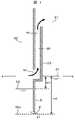
図1,図4は、ドライヤスカートの断面図を示す。図4は原子炉水位が通常時の場合を示し、図1は原子炉水位が大きく低下している場合を示す。 1 and 4 show sectional views of a dryer skirt. FIG. 4 shows a case where the reactor water level is normal, and FIG. 1 shows a case where the reactor water level is greatly lowered.
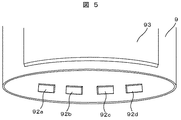
図4に示すように、ドライヤスカート9の下部にドライヤスカート内外を連通させる連通穴92を設けている。この連通穴92は周方向に複数設けられている(図5)。ドライヤスカート9の外側には、連通穴92を覆い鉛直上方に伸びるカバー93を取り付けている。このカバーの開口部94は、ドライヤスカート内水位32が連通穴92の位置まで低下したときに、ドライヤスカート外蒸気空間51に露出する位置に設けている。通常時には、カバーの開口部94はドライヤスカート外蒸気空間51に露出している必要はない。
As shown in FIG. 4, a
図1に示すように原子炉水位31が異常に低下すると、ドライヤ5の圧力損失が変化しなければ、ドライヤスカート内外の水位差H0は保持される。そのため、連通穴92がない場合、ドライヤスカート内水位が32aの位置まで低下し、ドライヤスカート下端91から蒸気が漏れ出す可能性がある。連通穴92を設けた場合、ドライヤスカート内水位32が連通穴92の位置に到達し、開口部94もドライヤスカート外蒸気空間51に露出する。そして、ドライヤスカート内蒸気空間52とドライヤスカート外蒸気空間51が連結されるので、ドライヤスカート内の蒸気の一部はカバー93の流路95を通して連通穴よりも上方向に逃げ、ドライヤスカート外蒸気空間51へ放出される。ドライヤスカート9の中から外へ蒸気が流れる流路面積が増えるため、ドライヤスカート内の圧力が低下し、ドライヤスカート内外の水位差がH0からH1まで小さくなる。このため、出力を向上してドライヤスカート内外の水位差が大きくなっている場合でも、ドライヤスカート内水位が連通穴92に到達した時点で水位差を小さくすることができる。そのため、従来の下限水位まで原子炉水位31が低下してもドライヤスカート下端91から蒸気が漏れ出すことはない。このため、原子炉水位31の下限値を上げたり、ドライヤスカート9を長くしたりする必要がなく、出力向上幅を拡大できる。
As shown in FIG. 1, if the
カバー93は各連通穴91a,91b,91c,91dにそれぞれ取り付けてもよいが、図5のように複数の連通穴91に対して一つの大きいカバー93を取り付けてもよい。この場合、部品点数を削減できるため、コストを低減することができる。
The
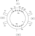
図7は、図1のAA断面図を示す。沸騰水型原子炉において、4本の主蒸気配管27は周方向に等間隔で配置されておらず、90°および270°の方向に各2本ずつ集中して配置されている(図7において、主蒸気配管27aと27cの中間を0°と規定し、時計回りに角度を規定する)。ドライヤスカート内の蒸気が連通穴92を通過するときに、蒸気がドライヤスカート内水面32から液滴を捕捉してドライヤスカート外蒸気空間51に流れ、その液滴を伴ったまま主蒸気配管27を通ってタービンへ流れ込む可能性がある。湿分が多いと、主蒸気配管27やタービンの腐食等の問題を引き起こす可能性があるため、過度の湿分は好ましくない。そこで、連通穴92の位置を主蒸気配管27から離れた図7の0°および180°の位置を中心に配置している。この配置により、連通穴92から主蒸気配管27の入口までに距離があるため、蒸気内の液滴は重力の作用で落下し、タービンへ送られる液滴量を低減することができる。
FIG. 7 is a cross-sectional view taken along the line AA in FIG. In the boiling water reactor, the four
また、ドライヤスカート外側に取り付けたカバー93はドライヤスカート9の補強にもなり、ドライヤの信頼性を向上させることができる。なお、カバー93をドライヤスカート9に取り付ける際、周方向の途中に一つないしは複数の補強板99を設置すると強度が向上する。
Further, the
このように、本実施例のドライヤスカートは、ドライヤスカートの内外を連通させる連通穴と、その連通穴を覆うとともに、連通穴から流出した蒸気が連通穴よりも上方向に逃げ、蒸気を放出する開口部を有したカバーを備えることにより、ドライヤスカートを補強し、かつ、出力向上幅を拡大することができる。 As described above, the dryer skirt of the present embodiment covers the communication hole that connects the inside and the outside of the dryer skirt, and covers the communication hole, and the steam that has flowed out of the communication hole escapes upward from the communication hole and releases the steam. By providing the cover having the opening, the dryer skirt can be reinforced and the output improvement width can be expanded.
図6を用いて実施例2を説明する。本実施例が実施例1と異なるのは、カバー93の開口部94をL字型部材96で覆っていることである。このL字型部材96には以下の効果がある。
Example 2 will be described with reference to FIG. The present embodiment is different from the first embodiment in that the
連通穴92を通ってカバー93に流入する蒸気は、気水分離器4から排出された蒸気である。この蒸気はドライヤ5を通過した蒸気よりも湿分が多い。また、ドライヤスカート内の蒸気が連通穴92に進入する際に、ドライヤスカート内の液面を乱して液滴を捕捉する可能性がある。連通穴92を通過する蒸気量が多くなりタービンへ運ばれる湿分が多くなると、主蒸気配管27やタービンの腐食等の問題が発生する。
The steam flowing into the
そこで、開口部94をL字型部材96で覆うことにより、蒸気流21はL字型部材96のところで大きく曲げられる。蒸気中に含まれる液滴は、蒸気との密度差による遠心分離作用でL字型部材96に衝突し、L字型部材96の内側表面に液膜33を形成する。この液膜33は、蒸気流21によって外側に流され、ドライヤスカート外の液面に落下する。このとき、液膜33は蒸気流21の中を落下することになる。なお、L字型部材96で液膜33を形成させて大きな塊としているので、蒸気流21に再び捕捉されてタービンに運ばれる液量の割合は、L字型部材を設けない場合よりも低減する。
Therefore, by covering the
L字型部材96を取り付けたことにより、連通穴92からドライヤスカート外蒸気空間51までの流路抵抗が増えて圧力損失が増加する。そのため、ドライヤスカート内外の水位差H2は実施例1の水位差H1と比較すると若干大きくなるが、連通穴92を設けない場合の水位差H0と比較すると小さくすることができる。
By attaching the L-shaped
図8および図9を用いて実施例3を説明する。本実施例が実施例2と異なる点は、開口部94を覆っているL字型部材96の終端に液膜33を集めて排出するドレン用溝97を設けたことである。このドレン用溝97は、L字型部材96の周方向終端まで伸びている。そして、L字型部材96の周方向終端部に液膜33の排出管98が設けられている(図9)。このドレン用溝97には以下の効果がある。
Example 3 will be described with reference to FIGS. This embodiment differs from the second embodiment in that a
実施例2で説明したように、割合はわずかであるが、L字型部材96から落下する液膜33が蒸気流21に再び捕捉されてタービンへ運ばれる。また、カバー93を通過する蒸気量が増加すると、ドライヤスカート内の液面から捕捉される液滴が増加し、液膜33の絶対量が増えて湿分が過剰になる可能性がある。
As described in the second embodiment, the
そこで本実施例では、L字型部材96の終端にドレン用溝97を設けて、L字型部材96に形成された液膜33をこのドレン用溝97に集める。集めた液膜33は、L字型部材96の周方向終端部に設けた排水管98へ供給し、液膜33をドライヤスカート外の液面に戻している。L字型部材96で集められた液膜33を開口部94から排出された蒸気流21の中を通過させずにドライヤスカート外の液面に戻すことができるため、液膜33が再び蒸気流21に捕捉されてタービンへ送られることを防ぐことができる。
In this embodiment, therefore, a
L字型部材96にドレン用溝97を取り付けたことにより、連通穴92からドライヤスカート外蒸気空間51までの流路抵抗が増えて圧力損失が増加し、ドライヤスカート内外の水位差H3は実施例2の水位差H2と比較すると若干大きくなる。但し、連通穴92を設けない場合の水位差H0と比較して、水位差を小さくすることができる。
By attaching the
本発明は、沸騰水型原子炉に適用可能である。 The present invention is applicable to a boiling water reactor.
1 原子炉圧力容器
2 炉心
3 炉心シュラウド
4 気水分離器
5 蒸気乾燥器(ドライヤ)
6 ダウンカマ
7 再循環系配管
8 再循環ポンプ
9 ドライヤスカート
11 ジェットポンプ
12 ライザ管
21 蒸気流
27,27a,27b,27c,27d 主蒸気配管
28 給水配管
29 下部プレナム
31 原子炉水位
32,32a ドライヤスカート内水位
33 液膜
34 冷却水
41 第一バレル排水路出口
51 ドライヤスカート外蒸気空間
52 ドライヤスカート内蒸気空間
91 ドライヤスカート下端
92,92a,92b,92c,92d 連通穴
93,93a,93b カバー
94 開口部
95 流路
96 L字型部材
97 ドレン用溝
98 排水管
99a,99b 補強板
1
6 Downcomer 7 Recirculation pipe 8 Recirculation pump 9
Claims (6)
前記気水分離器の上部に設けられた蒸気乾燥機と、
前記蒸気乾燥機の下部に接続され、前記気水分離器の外周側を円筒状に囲むドライヤスカートとを備え、
前記ドライヤスカートは、
前記ドライヤスカートの内外を連通させる連通穴と、
前記連通穴を覆うとともに、前記連通穴から流出した蒸気が前記連通穴よりも上方向に逃げ、前記蒸気を放出する開口部を有したカバーを備えることを特徴とする沸騰水型原子炉。 A steam separator for separating moisture mixed in the steam;
A steam dryer provided at the top of the steam separator;
A dryer skirt connected to the lower part of the steam dryer and surrounding the outer peripheral side of the steam separator cylindrically;
The dryer skirt is
A communication hole for communicating the inside and outside of the dryer skirt;
A boiling water reactor comprising a cover that covers the communication hole and has an opening through which steam that has flowed out of the communication hole escapes upward from the communication hole and discharges the steam.
Priority Applications (1)
| Application Number | Priority Date | Filing Date | Title |
|---|---|---|---|
| JP2009221818A JP5297962B2 (en) | 2009-09-28 | 2009-09-28 | Boiling water reactor |
Applications Claiming Priority (1)
| Application Number | Priority Date | Filing Date | Title |
|---|---|---|---|
| JP2009221818A JP5297962B2 (en) | 2009-09-28 | 2009-09-28 | Boiling water reactor |
Publications (2)
| Publication Number | Publication Date |
|---|---|
| JP2011069752A true JP2011069752A (en) | 2011-04-07 |
| JP5297962B2 JP5297962B2 (en) | 2013-09-25 |
Family
ID=44015153
Family Applications (1)
| Application Number | Title | Priority Date | Filing Date |
|---|---|---|---|
| JP2009221818A Expired - Fee Related JP5297962B2 (en) | 2009-09-28 | 2009-09-28 | Boiling water reactor |
Country Status (1)
| Country | Link |
|---|---|
| JP (1) | JP5297962B2 (en) |
Citations (4)
| Publication number | Priority date | Publication date | Assignee | Title |
|---|---|---|---|---|
| JPS63210698A (en) * | 1987-02-26 | 1988-09-01 | 株式会社日立製作所 | Steam drier for nuclear reactor |
| JPS63217106A (en) * | 1987-03-06 | 1988-09-09 | 株式会社日立製作所 | Gas-liquid separating structure and steam generator using said structure |
| JP2005233866A (en) * | 2004-02-23 | 2005-09-02 | Toshiba Corp | Steam dryer for boiling water nuclear reactor |
| JP2008116334A (en) * | 2006-11-06 | 2008-05-22 | Toshiba Corp | Natural circulation reactor and method for controlling its output |
-
2009
- 2009-09-28 JP JP2009221818A patent/JP5297962B2/en not_active Expired - Fee Related
Patent Citations (4)
| Publication number | Priority date | Publication date | Assignee | Title |
|---|---|---|---|---|
| JPS63210698A (en) * | 1987-02-26 | 1988-09-01 | 株式会社日立製作所 | Steam drier for nuclear reactor |
| JPS63217106A (en) * | 1987-03-06 | 1988-09-09 | 株式会社日立製作所 | Gas-liquid separating structure and steam generator using said structure |
| JP2005233866A (en) * | 2004-02-23 | 2005-09-02 | Toshiba Corp | Steam dryer for boiling water nuclear reactor |
| JP2008116334A (en) * | 2006-11-06 | 2008-05-22 | Toshiba Corp | Natural circulation reactor and method for controlling its output |
Also Published As
| Publication number | Publication date |
|---|---|
| JP5297962B2 (en) | 2013-09-25 |
Similar Documents
| Publication | Publication Date | Title |
|---|---|---|
| CN102282628B (en) | Reactor vessel coolant deflector shield | |
| US8424566B2 (en) | Apparatus and systems to control a fluid | |
| JPH10221480A (en) | Steam separator, atomic power plant and boiler device | |
| SE540363C2 (en) | Steam separator and nuclear boiling water reactor including the same background | |
| JP5297962B2 (en) | Boiling water reactor | |
| EP2156094B1 (en) | Blow-off tank for heat recovery steam generators | |
| JP6312935B2 (en) | Deaerator (option) | |
| US20060010869A1 (en) | Deaerating and degassing system for power plant condensers | |
| KR20130103764A (en) | Method for filling water into a main circuit of a nuclear reactor, and connection device for implementing said method | |
| JP2010271147A (en) | Nuclear reactor containment structure | |
| US5896431A (en) | Systems and methods for preventing steam leakage between a drywell and a wetwell in a nuclear reactor | |
| WO2021102885A1 (en) | Vertical type steam generator of pressurized water reactor nuclear power plant and loosening part capturing device therefor | |
| JP2018009723A (en) | Condenser | |
| JP2012058113A (en) | Steam separation facility for nuclear reactor | |
| JP5795914B2 (en) | Rotating electric machine with gas purity maintenance device | |
| JP5663324B2 (en) | Steam separator and boiling water reactor using the same | |
| JP2011191080A (en) | Steam separator for nuclear reactor | |
| JP7168519B2 (en) | Reactor cooling systems and nuclear plants | |
| JP2010243266A (en) | Boiling water reactor | |
| CN107119161A (en) | A kind of blast furnace gas dewatering and its dehydration device | |
| CN218469611U (en) | Steam jet vacuum system of condenser and variable working condition self-balancing free type drainage structure | |
| JP2863610B2 (en) | Steam turbine condenser | |
| JP2012117857A (en) | Steam separator | |
| EP3893251A1 (en) | Nuclear power station pressurizer and water sealing device thereof | |
| JPH02294502A (en) | Preparatory moisture content separator for steam turbine |
Legal Events
| Date | Code | Title | Description |
|---|---|---|---|
| A621 | Written request for application examination |
Free format text: JAPANESE INTERMEDIATE CODE: A621 Effective date: 20110629 |
|
| A521 | Request for written amendment filed |
Free format text: JAPANESE INTERMEDIATE CODE: A523 Effective date: 20110629 |
|
| TRDD | Decision of grant or rejection written | ||
| A01 | Written decision to grant a patent or to grant a registration (utility model) |
Free format text: JAPANESE INTERMEDIATE CODE: A01 Effective date: 20130521 |
|
| A61 | First payment of annual fees (during grant procedure) |
Free format text: JAPANESE INTERMEDIATE CODE: A61 Effective date: 20130617 |
|
| R150 | Certificate of patent or registration of utility model |
Ref document number: 5297962 Country of ref document: JP Free format text: JAPANESE INTERMEDIATE CODE: R150 Free format text: JAPANESE INTERMEDIATE CODE: R150 |
|
| LAPS | Cancellation because of no payment of annual fees |