JP2011069367A - Electrical turbocharger - Google Patents
Electrical turbocharger Download PDFInfo
- Publication number
- JP2011069367A JP2011069367A JP2010212170A JP2010212170A JP2011069367A JP 2011069367 A JP2011069367 A JP 2011069367A JP 2010212170 A JP2010212170 A JP 2010212170A JP 2010212170 A JP2010212170 A JP 2010212170A JP 2011069367 A JP2011069367 A JP 2011069367A
- Authority
- JP
- Japan
- Prior art keywords
- cooling
- passage
- cooling plate
- turbocharger
- refrigerant
- Prior art date
- Legal status (The legal status is an assumption and is not a legal conclusion. Google has not performed a legal analysis and makes no representation as to the accuracy of the status listed.)
- Granted
Links
Images
Classifications
-
- F—MECHANICAL ENGINEERING; LIGHTING; HEATING; WEAPONS; BLASTING
- F02—COMBUSTION ENGINES; HOT-GAS OR COMBUSTION-PRODUCT ENGINE PLANTS
- F02B—INTERNAL-COMBUSTION PISTON ENGINES; COMBUSTION ENGINES IN GENERAL
- F02B39/00—Component parts, details, or accessories relating to, driven charging or scavenging pumps, not provided for in groups F02B33/00 - F02B37/00
- F02B39/02—Drives of pumps; Varying pump drive gear ratio
- F02B39/08—Non-mechanical drives, e.g. fluid drives having variable gear ratio
- F02B39/10—Non-mechanical drives, e.g. fluid drives having variable gear ratio electric
-
- F—MECHANICAL ENGINEERING; LIGHTING; HEATING; WEAPONS; BLASTING
- F01—MACHINES OR ENGINES IN GENERAL; ENGINE PLANTS IN GENERAL; STEAM ENGINES
- F01D—NON-POSITIVE DISPLACEMENT MACHINES OR ENGINES, e.g. STEAM TURBINES
- F01D25/00—Component parts, details, or accessories, not provided for in, or of interest apart from, other groups
- F01D25/08—Cooling; Heating; Heat-insulation
- F01D25/12—Cooling
-
- F—MECHANICAL ENGINEERING; LIGHTING; HEATING; WEAPONS; BLASTING
- F02—COMBUSTION ENGINES; HOT-GAS OR COMBUSTION-PRODUCT ENGINE PLANTS
- F02B—INTERNAL-COMBUSTION PISTON ENGINES; COMBUSTION ENGINES IN GENERAL
- F02B37/00—Engines characterised by provision of pumps driven at least for part of the time by exhaust
- F02B37/04—Engines with exhaust drive and other drive of pumps, e.g. with exhaust-driven pump and mechanically-driven second pump
- F02B37/10—Engines with exhaust drive and other drive of pumps, e.g. with exhaust-driven pump and mechanically-driven second pump at least one pump being alternatively or simultaneously driven by exhaust and other drive, e.g. by pressurised fluid from a reservoir or an engine-driven pump
-
- F—MECHANICAL ENGINEERING; LIGHTING; HEATING; WEAPONS; BLASTING
- F02—COMBUSTION ENGINES; HOT-GAS OR COMBUSTION-PRODUCT ENGINE PLANTS
- F02B—INTERNAL-COMBUSTION PISTON ENGINES; COMBUSTION ENGINES IN GENERAL
- F02B39/00—Component parts, details, or accessories relating to, driven charging or scavenging pumps, not provided for in groups F02B33/00 - F02B37/00
- F02B39/005—Cooling of pump drives
-
- F—MECHANICAL ENGINEERING; LIGHTING; HEATING; WEAPONS; BLASTING
- F02—COMBUSTION ENGINES; HOT-GAS OR COMBUSTION-PRODUCT ENGINE PLANTS
- F02C—GAS-TURBINE PLANTS; AIR INTAKES FOR JET-PROPULSION PLANTS; CONTROLLING FUEL SUPPLY IN AIR-BREATHING JET-PROPULSION PLANTS
- F02C6/00—Plural gas-turbine plants; Combinations of gas-turbine plants with other apparatus; Adaptations of gas-turbine plants for special use
- F02C6/04—Gas-turbine plants providing heated or pressurised working fluid for other apparatus, e.g. without mechanical power output
- F02C6/10—Gas-turbine plants providing heated or pressurised working fluid for other apparatus, e.g. without mechanical power output supplying working fluid to a user, e.g. a chemical process, which returns working fluid to a turbine of the plant
- F02C6/12—Turbochargers, i.e. plants for augmenting mechanical power output of internal-combustion piston engines by increase of charge pressure
-
- F—MECHANICAL ENGINEERING; LIGHTING; HEATING; WEAPONS; BLASTING
- F04—POSITIVE - DISPLACEMENT MACHINES FOR LIQUIDS; PUMPS FOR LIQUIDS OR ELASTIC FLUIDS
- F04D—NON-POSITIVE-DISPLACEMENT PUMPS
- F04D25/00—Pumping installations or systems
- F04D25/02—Units comprising pumps and their driving means
- F04D25/06—Units comprising pumps and their driving means the pump being electrically driven
- F04D25/068—Mechanical details of the pump control unit
-
- F—MECHANICAL ENGINEERING; LIGHTING; HEATING; WEAPONS; BLASTING
- F04—POSITIVE - DISPLACEMENT MACHINES FOR LIQUIDS; PUMPS FOR LIQUIDS OR ELASTIC FLUIDS
- F04D—NON-POSITIVE-DISPLACEMENT PUMPS
- F04D29/00—Details, component parts, or accessories
- F04D29/58—Cooling; Heating; Diminishing heat transfer
- F04D29/5813—Cooling the control unit
-
- Y—GENERAL TAGGING OF NEW TECHNOLOGICAL DEVELOPMENTS; GENERAL TAGGING OF CROSS-SECTIONAL TECHNOLOGIES SPANNING OVER SEVERAL SECTIONS OF THE IPC; TECHNICAL SUBJECTS COVERED BY FORMER USPC CROSS-REFERENCE ART COLLECTIONS [XRACs] AND DIGESTS
- Y02—TECHNOLOGIES OR APPLICATIONS FOR MITIGATION OR ADAPTATION AGAINST CLIMATE CHANGE
- Y02T—CLIMATE CHANGE MITIGATION TECHNOLOGIES RELATED TO TRANSPORTATION
- Y02T10/00—Road transport of goods or passengers
- Y02T10/10—Internal combustion engine [ICE] based vehicles
- Y02T10/12—Improving ICE efficiencies
Landscapes
- Engineering & Computer Science (AREA)
- Mechanical Engineering (AREA)
- General Engineering & Computer Science (AREA)
- Chemical & Material Sciences (AREA)
- Combustion & Propulsion (AREA)
- Physics & Mathematics (AREA)
- Thermal Sciences (AREA)
- Chemical Kinetics & Catalysis (AREA)
- General Chemical & Material Sciences (AREA)
- Supercharger (AREA)
Abstract
【課題】冷却通路内での冷媒の流れを最適化することができ、冷却通路を簡単に製造することができるようにする。
【解決手段】冷却装置が、冷却プレート2を有しており、該冷却プレート2が、冷媒のための溝状に開放した少なくとも1つの冷却通路19を有しており、電気的なターボチャージャ1の少なくとも1つの構成部材への冷却プレート2の当付けによって、開放した冷却通路19が閉鎖されているようにした。
【選択図】図1A refrigerant flow in a cooling passage can be optimized and a cooling passage can be easily manufactured.
The cooling device includes a cooling plate, and the cooling plate includes at least one cooling passage opened in a groove shape for the refrigerant. The open cooling passage 19 was closed by applying the cooling plate 2 to at least one of the components.
[Selection] Figure 1
Description
本発明は、電気的なターボチャージャであって、冷却装置に対応配置された少なくとも1つの構成部材が設けられている形式のものに関する。 The present invention relates to an electrical turbocharger of the type provided with at least one component arranged corresponding to a cooling device.
さらに、本発明は、装置を冷却するための冷却プレートの使用であって、該冷却プレートが、冷媒のための溝状に開放した少なくとも1つの冷却通路を有しており、前記装置の少なくとも1つの構成部材への前記冷却プレートの当付けによって、開放した前記冷却通路を閉鎖する形式のものに関する。 Furthermore, the present invention is the use of a cooling plate for cooling the device, the cooling plate having at least one cooling passage open in the form of a groove for the refrigerant, wherein at least one of the devices The present invention relates to a type in which the opened cooling passage is closed by applying the cooling plate to one component.
冒頭で述べた形式の電気的なターボチャージャは、公知先行技術に基づき公知である。この公知の電気的なターボチャージャは、電動モータと、コンプレッサと、出力電子装置と、選択的にタービンとから成っている。電動モータは、ステータと、軸を備えたロータとを有している。コンプレッサはコンプレッサホイールを有しており、タービンはタービンホイールを有している。出力電子装置は電動モータに電気的に接続されていて、この電動モータに運転状況に応じて電気的なエネルギを供給する。電気的なターボチャージャの運転時には、電動モータが電気的なエネルギを機械的な回転運動に変換する。この場合、軸を備えたロータがステータ内で回転する。軸は回転運動をコンプレッサホイールに伝達する。この場合、軸方向でコンプレッサホイールに流入した空気が、圧縮されて半径方向に流出する。選択的には、半径方向で内燃機関の排ガスがタービンホイールに流入する。これによって、このタービンホイールの回転運動が発生させられる。この回転運動は軸に伝達される。したがって、少なくとも一時的に電動モータに対して付加的にまたは択一的にタービンによる軸の駆動ひいてはコンプレッサの駆動が可能となる。電気的なターボチャージャにおいて圧縮された空気は、特に燃料電池を有する原動機に対して設けられている。この場合、圧縮された空気内の酸素が燃料電池の運転のために使用される。択一的には、電気的なターボチャージャにおいて圧縮された空気が、内燃機関を有する車両において内燃機関内での過給圧増大のために使用される。電気的なターボチャージャの運転時には、熱が発生させられ、したがって、この熱が冷却されなければならない。冷媒を電気的なターボチャージャ内で冷却通路によって分配するためには、特に電気的なターボチャージャのケーシングに複数の孔が設けられている。これらの孔は直線状であるので、冷却通路に所定の角度を実現するためには、互いに交差する少なくとも2つの孔が使用されなければならない。これらの互いに交差する孔によって、冷媒がほぼ運動せずに停滞する死水域が形成され、さらに、冷却通路のコーナ状の経過、つまり、角度を備えて屈曲した道筋が生じる。したがって、冷却通路に流体技術的に接続された冷媒ポンプの高められた出力消費を結果的に招く冷媒の流れ損失が生じる。更なる欠点は、必要となる大きな個数の孔に対する高い製造手間ならびに孔のばり取りに対する高い手間である。 An electric turbocharger of the type mentioned at the beginning is known from the prior art. This known electric turbocharger consists of an electric motor, a compressor, output electronics, and optionally a turbine. The electric motor has a stator and a rotor having a shaft. The compressor has a compressor wheel, and the turbine has a turbine wheel. The output electronic device is electrically connected to the electric motor, and supplies electric energy to the electric motor according to the operating condition. When the electric turbocharger is in operation, the electric motor converts electrical energy into mechanical rotational motion. In this case, the rotor provided with the shaft rotates in the stator. The shaft transmits rotational motion to the compressor wheel. In this case, the air flowing into the compressor wheel in the axial direction is compressed and flows out in the radial direction. Optionally, the exhaust gas of the internal combustion engine flows into the turbine wheel in the radial direction. Thereby, the rotational movement of this turbine wheel is generated. This rotational motion is transmitted to the shaft. Therefore, at least temporarily, additionally or alternatively to the electric motor, it is possible to drive the shaft by the turbine and hence the compressor. The air compressed in the electric turbocharger is provided in particular for a prime mover having a fuel cell. In this case, oxygen in the compressed air is used for the operation of the fuel cell. Alternatively, air compressed in an electric turbocharger is used for increasing the boost pressure in the internal combustion engine in a vehicle with the internal combustion engine. During operation of an electrical turbocharger, heat is generated and therefore this heat must be cooled. In order to distribute the refrigerant in the electric turbocharger by the cooling passage, a plurality of holes are provided in the casing of the electric turbocharger in particular. Since these holes are straight, at least two holes that intersect each other must be used to achieve a predetermined angle in the cooling passage. These intersecting holes form a dead water area in which the refrigerant stagnates without substantially moving, and further, a corner-like course of the cooling passage, that is, a curved path with an angle. Consequently, refrigerant flow losses result which result in increased power consumption of the refrigerant pump connected in the fluid path to the cooling passage. A further disadvantage is the high manufacturing effort for the large number of holes required and the high effort for deburring the holes.
したがって、本発明の課題は、冒頭で述べた形式の電気的なターボチャージャを改良して、冷却通路内での冷媒の流れを最適化することができ、冷却通路を簡単に製造することができるようにすることである。 Therefore, the object of the present invention is to improve the electric turbocharger of the type described at the beginning, to optimize the flow of the refrigerant in the cooling passage, and to easily manufacture the cooling passage. Is to do so.
この課題を解決するために本発明に係る電気的なターボチャージャでは、前記冷却装置が、冷却プレートを有しており、該冷却プレートが、冷媒のための溝状に開放した少なくとも1つの冷却通路を有しており、電気的なターボチャージャの前記少なくとも1つの構成部材への冷却プレートの当付けによって、開放した冷却通路が閉鎖されているようにした。 In order to solve this problem, in the electric turbocharger according to the present invention, the cooling device has a cooling plate, and the cooling plate opens in a groove shape for the refrigerant. The open cooling passage is closed by applying the cooling plate to the at least one component of the electric turbocharger.
本発明に係る電気的なターボチャージャの有利な態様によれば、前記構成部材が、出力電子装置、電動モータ、コンプレッサおよび/またはタービンである。 According to an advantageous aspect of the electrical turbocharger according to the invention, the component is an output electronic device, an electric motor, a compressor and / or a turbine.
本発明に係る電気的なターボチャージャの有利な態様によれば、冷却プレートの1つまたはそれ以上の面が、前記少なくとも1つの構成部材に接触している。 According to an advantageous embodiment of the electrical turbocharger according to the invention, one or more faces of the cooling plate are in contact with the at least one component.
本発明に係る電気的なターボチャージャの有利な態様によれば、冷却プレートが、出力電子装置と電動モータとの間にそれぞれ接触して配置されている。 According to an advantageous embodiment of the electrical turbocharger according to the invention, the cooling plates are arranged in contact with each other between the output electronic device and the electric motor.
本発明に係る電気的なターボチャージャの有利な態様によれば、冷却プレートが、別個の構成エレメントとして形成されているかまたは出力電子装置および/または電動モータと一体に形成されている。 According to an advantageous embodiment of the electrical turbocharger according to the invention, the cooling plate is formed as a separate component or formed integrally with the output electronics and / or the electric motor.
本発明に係る電気的なターボチャージャの有利な態様によれば、冷却プレートが、少なくとも1つの接続通路を有しており、該接続通路が、冷却通路に開口している。 According to an advantageous embodiment of the electrical turbocharger according to the invention, the cooling plate has at least one connection passage, which opens into the cooling passage.
本発明に係る電気的なターボチャージャの有利な態様によれば、接続通路が、冷却プレートを貫通した接続通路である。 According to an advantageous aspect of the electrical turbocharger according to the invention, the connection passage is a connection passage through the cooling plate.
本発明に係る電気的なターボチャージャの有利な態様によれば、接続通路が、冷却プレートを貫通した孔である。 According to an advantageous aspect of the electrical turbocharger according to the invention, the connection passage is a hole penetrating the cooling plate.
本発明に係る電気的なターボチャージャの有利な態様によれば、前記構成部材への冷却プレートの当付けによって冷却通路および/または接続通路に連通接続されると共に電気的なターボチャージャの少なくとも1つの冷却箇所に通じる少なくとも1つの接続通路が設けられている。 According to an advantageous aspect of the electrical turbocharger according to the present invention, at least one of the electrical turbocharger is connected in communication with the cooling passage and / or the connection passage by applying the cooling plate to the component. At least one connecting passage leading to the cooling point is provided.
本発明に係る電気的なターボチャージャの有利な態様によれば、前記冷却箇所が、出力電子装置のエレメント、電動モータのエレメント、コンプレッサのエレメントおよび/またはタービンのエレメントである。 According to an advantageous embodiment of the electrical turbocharger according to the invention, the cooling point is an element of the output electronics, an element of the electric motor, an element of the compressor and / or an element of the turbine.
本発明に係る電気的なターボチャージャの有利な態様によれば、接続通路が、少なくとも部分的に冷却螺線通路および/または冷却室として形成されている。 According to an advantageous embodiment of the electrical turbocharger according to the invention, the connection passage is at least partly formed as a cooling spiral passage and / or a cooling chamber.
本発明に係る電気的なターボチャージャの有利な態様によれば、冷却プレートの1つの面に冷媒流入通路が形成されており、冷却プレートの別の面または同一の面に冷媒流出通路が形成されている。 According to an advantageous aspect of the electric turbocharger according to the present invention, the refrigerant inflow passage is formed on one surface of the cooling plate, and the refrigerant outflow passage is formed on another surface or the same surface of the cooling plate. ing.
さらに、前述した課題を解決するために本発明に係る使用では、前記装置として電気的なターボチャージャを使用するようにした。 Furthermore, in order to solve the above-described problems, an electric turbocharger is used as the device in the use according to the present invention.
本発明に係る使用の有利な態様によれば、電気的なターボチャージャが、前記構成部材として、出力電子装置、電動モータ、コンプレッサおよび/またはタービンを有しており、前記構成部材の少なくとも1つに冷却プレートを接触させる。 According to an advantageous embodiment of the use according to the invention, an electrical turbocharger has, as said component, an output electronic device, an electric motor, a compressor and / or a turbine, and at least one of said component Bring the cooling plate into contact.
請求項1に記載した特徴を備えた電気的なターボチャージャは従来のものに比べて、冷却装置の簡単なかつフレキシブルな製造が可能となるという利点を有している。なぜならば、冷媒のための溝状に開放した少なくとも1つの冷却通路を備えた冷却プレートが、冷却装置の一部として設けられているからである。有利には、冷却通路を備えた冷却プレートはダイカスト法で製造されており、択一的には、冷却通路がフライス削りまたはエッチングによって冷却プレートに加工されている。有利には、冷却通路は少なくとも部分的にメアンダ状に形成されている。これによって、冷却通路内での冷媒の最適な流れが可能となり、これによって、冷媒ポンプの出力消費の低減が結果的に達成される。本発明は、電気的なターボチャージャの少なくとも1つの構成部材への冷却プレートの当付けによって、開放した冷却通路が閉鎖されていることを提案している。これによって、電気的なターボチャージャの運転時に冷媒と電気的なターボチャージャの構成部材との直接的な接触が付与されている。特に冷却通路は1つの構成部材によって閉鎖されている。択一的には、複数の冷却通路が1つまたはそれ以上の構成部材によって閉鎖されていることも可能である。したがって、冷却プレートを用いて接触によってターボチャージャの少なくとも1つの構成部材が冷却される。冷却プレートの開放した冷却通路は、この冷却通路の横断面に対して垂直方向での構成部材への冷却プレートの当付けによって閉鎖されている。冷却通路はその両端部において、特にその横断面に対して平行に冷媒流入通路と冷媒流出通路とを有している。電気的なターボチャージャの運転時には、冷媒が冷媒流入通路に流入し、冷却通路を通って流れ、冷媒流出通路から流出する。冷却プレートは、特に良熱伝導性を備えた材料、有利には銅から成っているかまたは、択一的には、銀、金またはアルミニウムから成っているかまたは銅、銀、金および/またはアルミニウムを含有した金属合金から成っている。冷媒は、特に水であり、択一的には、水性の溶液、オイル、空気または別の液状のまたはガス状の冷媒が設けられていてよい。冷却プレートと構成部材とは、特にねじ締結によって互いに固定されている。択一的には、冷却プレートと構成部材とがろう接、接着またはクランプによって互いに固定されていてよい。有利には、それぞれ1つのシール部材が、冷却通路に対して平行に延びる溝内に嵌め込まれている。この溝は冷却通路の両側に形成されている。択一的には、冷却プレートと構成部材との間にシールコンパウンドが設けられていてよい。
The electric turbocharger having the features described in
本発明の改良態様は、構成部材が、出力電子装置、電動モータ、コンプレッサおよび/またはタービンであることを提案している。構成部材は、電気的なターボチャージャのケーシングの分割ケーシングを有している。構成部材への冷却プレートの当付けによって、分割ケーシングが、冷媒と、この冷媒を介して冷却された冷却プレートとの接触により効果的に冷却される。 The refinement of the invention proposes that the component is an output electronic device, an electric motor, a compressor and / or a turbine. The component has a split casing which is an electrical turbocharger casing. By applying the cooling plate to the component member, the divided casing is effectively cooled by the contact between the refrigerant and the cooling plate cooled via the refrigerant.
さらに、冷却プレートの1つまたはそれ以上の面が、少なくとも1つの構成部材に接触していることが提案されている。特に冷却プレートのそれぞれ1つの面が、それぞれ1つの構成部材に接触している。択一的には、冷却プレートの1つの面が、複数の構成部材に接触しているかまたは冷却プレートの複数の面が、少なくとも部分的にL字形のまたはU字形の1つの構成部材に接触していることが可能となる。 Furthermore, it has been proposed that one or more surfaces of the cooling plate are in contact with at least one component. In particular, each one surface of the cooling plate is in contact with one component. Alternatively, one surface of the cooling plate is in contact with a plurality of components, or a plurality of surfaces of the cooling plate is in contact with one component at least partially L-shaped or U-shaped. It will be possible.
有利な改良態様では、冷却プレートが、出力電子装置と電動モータとの間にそれぞれ接触して配置されていることが提案されている。この場合、特に出力電子装置と電動モータとが、それぞれ少なくとも1つの開放した冷却通路を閉鎖する構成部材として設けられている。 In an advantageous refinement, it is proposed that the cooling plate is arranged in contact between the output electronics and the electric motor, respectively. In this case, in particular, the output electronic device and the electric motor are provided as components for closing at least one open cooling passage.
本発明の改良態様は、冷却プレートが、別個の構成エレメントとして形成されているかまたは出力電子装置および/または電動モータと一体に形成されていることを提案している。特に冷却プレートは別個の構成エレメントとして形成されている。なぜならば、このような構成の場合には、製造時に冷却プレートの全ての面に簡単に近づくことが可能となるからである。これによって、特に冷却通路の製造が簡単となる。択一的な一体の構成では、冷却プレートが、出力電子装置の分割ケーシングの少なくとも一区分および/または電動モータの分割ケーシングの少なくとも一区分と一体に形成されている。したがって、電気的なターボチャージャの組立て前の冷却プレートの製造時に出力電子装置および/または電動モータの内側の分割ケーシングにも近づくことができる。これによって、特に冷却通路の製造が容易になる。 The refinement of the invention proposes that the cooling plate is formed as a separate component or is formed integrally with the output electronics and / or the electric motor. In particular, the cooling plate is formed as a separate component. This is because in such a configuration, it becomes possible to easily approach all the surfaces of the cooling plate during manufacturing. This particularly simplifies the manufacture of the cooling passage. In an alternative integrated arrangement, the cooling plate is formed integrally with at least one section of the output electronics split casing and / or with at least one section of the electric motor split casing. Therefore, it is possible to approach the output electronics and / or the split casing inside the electric motor when manufacturing the cooling plate before the assembly of the electric turbocharger. This particularly facilitates the manufacture of the cooling passage.
さらに、冷却プレートが、少なくとも1つの接続通路を有しており、この接続通路が、冷却通路に開口していることが提案されている。接続通路は、特に閉鎖されていて、有利には円形の横断面を有している。択一的には、接続通路が溝状に形成されていてよい。この場合、この接続通路は、特に冷却通路を別の冷却通路に接続している。 Furthermore, it has been proposed that the cooling plate has at least one connection passage, which connection passage opens into the cooling passage. The connecting passage is particularly closed and preferably has a circular cross section. Alternatively, the connection passage may be formed in a groove shape. In this case, this connection passage connects in particular the cooling passage to another cooling passage.
本発明の改良態様は、接続通路が、冷却プレートを貫通した接続通路であることを提案している。特に接続通路は、冷却プレートの、最大の表面積を有する互いに反対の側の面を接続している。択一的には、接続通路がこれら両面の一方を、この面に対して垂直に配置された冷却プレート面に接続していてよい。原理的には、冷却プレートの考えられる全ての面の組合せ接続が可能となる。さらに、接続通路が別の接続通路に交差していて、したがって、接続通路網が形成されていることが可能となる。 The improved aspect of the invention proposes that the connection passage is a connection passage through the cooling plate. In particular, the connecting passage connects the opposite surfaces of the cooling plate with the largest surface area. Alternatively, a connection passage may connect one of these surfaces to a cooling plate surface arranged perpendicular to this surface. In principle, a combined connection of all possible surfaces of the cooling plate is possible. Furthermore, it is possible that the connection passage intersects with another connection passage, thus forming a connection passage network.
有利には、接続通路が、冷却プレートを貫通した孔であることが提案されている。この場合、この孔は、特に直線状に延びていて、円形の横断面を有している。このように形成された接続通路は、特に簡単に製造することができる。 Advantageously, it has been proposed that the connecting passage is a hole through the cooling plate. In this case, the hole extends in particular linearly and has a circular cross section. The connection passage formed in this way can be produced particularly easily.
本発明の改良態様は、電気的なターボチャージャが、構成部材への冷却プレートの当付けによって冷却通路および/または接続通路に連通接続されると共に電気的なターボチャージャの少なくとも1つの冷却箇所に通じる少なくとも1つの接続通路を有していることを提案している。この場合、「連通」とは、冷却プレートの接続通路から、冷却箇所に通じる接続通路への冷媒の流れまたは冷却箇所に通じる接続通路から冷却プレートの接続通路への冷媒の流れが提供されていることを意味している。この場合、構成部材は接続通路を少なくとも部分的に有している。構成部材が接続通路を完全に有している場合には、冷却箇所が構成部材内に位置している。構成部材が接続通路を部分的にしか有していない場合には、冷却箇所が電気的なターボチャージャの別の構成エレメントに位置している。冷却プレートの接続通路と、冷却通路に通じる接続通路との利点は、冷却プレートと構成部材との接触による冷却に対して付加的に、電気的なターボチャージャの、冷却プレートに接触しない構成エレメントを冷却プレートによって冷却することが可能となることである。構成部材への冷却プレートの当付け時には、冷却箇所に通じる接続通路の接触端部が冷却プレートの接続通路の接触端部に整合しており、かつ/または冷却箇所に通じる接続通路の接触端部が冷却通路に載置されている。特に冷却箇所に通じる接続通路の接触端部および/または冷却プレートの接続通路の接触端部を取り囲んで環状の溝が設けられている。この溝内には、環状のシール部材、有利にはゴムシール部材が嵌め込まれている。 The improvement of the invention is such that the electrical turbocharger is connected in communication to the cooling passage and / or the connection passage by the application of a cooling plate to the component and leads to at least one cooling point of the electrical turbocharger. It is proposed to have at least one connecting passage. In this case, “communication” means that the flow of the refrigerant from the connection passage of the cooling plate to the connection passage leading to the cooling location or the flow of the refrigerant from the connection passage leading to the cooling location to the connection passage of the cooling plate is provided. It means that. In this case, the component has at least partly a connecting passage. If the component has a complete connection passage, the cooling point is located in the component. If the component has only a partial connection passage, the cooling point is located in another component of the electrical turbocharger. The advantage of the connection passage of the cooling plate and the connection passage leading to the cooling passage is that, in addition to the cooling by the contact between the cooling plate and the component, the component of the electric turbocharger that does not contact the cooling plate is added. It is possible to cool by the cooling plate. When the cooling plate is applied to the structural member, the contact end of the connection passage leading to the cooling location is aligned with the contact end of the connection passage of the cooling plate and / or the contact end of the connection passage leading to the cooling location Is placed in the cooling passage. In particular, an annular groove is provided surrounding the contact end of the connection passage leading to the cooling location and / or the contact end of the connection passage of the cooling plate. An annular seal member, preferably a rubber seal member, is fitted in the groove.
本発明の改良態様は、冷却箇所が、出力電子装置のエレメント、電動モータのエレメント、コンプレッサのエレメントおよび/またはタービンのエレメントである。出力電子装置のエレメントは、特に電気的なターボチャージャの運転時に多くの熱が発生しかつ/または過熱によって容易に損傷し得るエレメントである。電動モータのエレメントは、特にステータおよび/または軸の少なくとも1つの軸受けであり、コンプレッサのエレメントは、特にコンプレッサの分割ケーシングであり、タービンのエレメントは、特にタービンの分割ケーシングである。 In an improved embodiment of the invention, the cooling point is an element of the output electronics, an element of the electric motor, an element of the compressor and / or an element of the turbine. The elements of the output electronics are elements that generate a lot of heat and / or can be easily damaged by overheating, especially during the operation of an electric turbocharger. The element of the electric motor is in particular at least one bearing of the stator and / or shaft, the element of the compressor is in particular a split casing of the compressor, and the element of the turbine is in particular a split casing of the turbine.
冷却箇所に通じる接続通路が、少なくとも部分的に冷却螺線通路および/または冷却室として形成されていると有利である。冷却螺線通路は、特に円形のまたは方形の横断面を有している。有利には、冷却螺線通路は電気的なターボチャージャの2つの構成エレメントの協働によって、一方の構成エレメントに形成された溝が他方の構成エレメントの溝または平滑な面によってカバーされることにより形成されている。これによって、冷却螺線通路の簡単な製造が可能となる。特にこの冷却螺線通路は螺線状に、たとえば電動モータのステータを取り囲んで延びている。択一的には、冷却螺線通路が少なくとも部分的にメアンダ状に1つのレベルに、たとえば出力電子装置の分割ケーシングに延びていてもよい。冷却室は、電気的なターボチャージャに設けられた室である。この室は原理的に任意のあらゆる形状をとることができる。特に冷却室は電動モータの軸を中心として円筒状に延びている。この場合、冷却室は、有利には軸の軸受けの冷却のために設けられている。 It is advantageous if the connecting passage leading to the cooling point is at least partly formed as a cooling spiral passage and / or a cooling chamber. The cooling spiral passage has a particularly circular or square cross section. Advantageously, the cooling spiral passage is formed by the cooperation of the two components of the electric turbocharger so that the groove formed in one component is covered by the groove or the smooth surface of the other component. Is formed. This allows a simple manufacturing of the cooling spiral passage. In particular, the cooling spiral passage extends in a spiral shape, for example, surrounding the stator of the electric motor. As an alternative, the cooling spiral passage may extend at least partially in a meandering manner to one level, for example to the split casing of the output electronics. The cooling chamber is a chamber provided in the electric turbocharger. This chamber can in principle take any arbitrary shape. In particular, the cooling chamber extends in a cylindrical shape around the axis of the electric motor. In this case, the cooling chamber is preferably provided for cooling the bearings of the shaft.
有利には、冷却プレートの1つの面に冷媒流入通路が形成されており、冷却プレートの別の面または同一の面に冷媒流出通路が形成されていることが提案されている。特に冷媒流出通路は冷却プレートの別の面に形成されている。このために、有利には冷却プレートの接続通路が両面を接続している。このような構成では、電気的なターボチャージャの運転中に冷却プレートの一方の側における冷媒が他方の側における冷媒よりも低い温度を有している。なぜならば、冷媒が冷却通路での通流の間に加熱されるからである。したがって、構成部材への一方の面の当付けによって、構成部材の効果的な冷却が可能となるという利点が得られる。 Advantageously, it has been proposed that a refrigerant inflow passage is formed on one surface of the cooling plate and a refrigerant outflow passage is formed on another surface or the same surface of the cooling plate. In particular, the refrigerant outflow passage is formed on another surface of the cooling plate. For this purpose, the connecting passages of the cooling plate advantageously connect both sides. In such a configuration, during operation of the electrical turbocharger, the refrigerant on one side of the cooling plate has a lower temperature than the refrigerant on the other side. This is because the refrigerant is heated during the flow through the cooling passage. Therefore, the advantage that the component member can be effectively cooled is obtained by applying the one surface to the component member.
さらに、本発明は、装置を冷却するための冷却プレートの使用であって、この冷却プレートが、冷媒のための溝状に開放した少なくとも1つの冷却通路を有しており、前述した装置の少なくとも1つの構成部材への冷却プレートの当付けによって、開放した冷却通路を閉鎖する形式のものに関する。本発明は、前述した装置として電気的なターボチャージャを使用することを提案している。したがって、冷却プレートの当付けによって、電気的なターボチャージャの少なくとも1つの構成部材が冷媒によって冷却される。この場合、冷却は、冷却プレートを通って流れる冷媒との接触だけでなく、この冷媒により冷却される冷却プレートとの接触によっても実現される。冷却通路は、有利には少なくとも部分的にメアンダ状に延びている。冷媒として、特に水が使用され、択一的には、水性の溶液、オイル、空気または別の液状のまたはガス状の冷媒が使用されてよい。 Furthermore, the present invention is the use of a cooling plate for cooling the device, the cooling plate having at least one cooling passage opened in a groove for the refrigerant, The present invention relates to a type in which an open cooling passage is closed by applying a cooling plate to one component. The present invention proposes to use an electrical turbocharger as the device described above. Therefore, the application of the cooling plate cools at least one component of the electric turbocharger with the refrigerant. In this case, the cooling is realized not only by contact with the refrigerant flowing through the cooling plate but also by contact with the cooling plate cooled by this refrigerant. The cooling passages preferably extend at least partially in a meander shape. As the refrigerant, in particular water is used, alternatively an aqueous solution, oil, air or another liquid or gaseous refrigerant may be used.
本発明の改良態様は、電気的なターボチャージャが、構成部材として、出力電子装置、電動モータ、コンプレッサおよび/またはタービンを有しており、構成部材の少なくとも1つに冷却プレートを接触させることを提案している。特に冷却プレートは出力電子装置と電動モータとの間にそれぞれ接触して配置されている。この場合、冷却プレートは両構成部材を接触によって冷却する。 According to an improved aspect of the present invention, the electric turbocharger has an output electronic device, an electric motor, a compressor and / or a turbine as a component, and the cooling plate is brought into contact with at least one of the components. is suggesting. In particular, the cooling plate is disposed in contact between the output electronic device and the electric motor. In this case, the cooling plate cools both components by contact.
以下に、本発明を実施するための形態を図面につき詳しく説明する。 In the following, embodiments for carrying out the present invention will be described in detail with reference to the drawings.
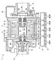
図1には、電気的なターボチャージャ1が示してある。この電気的なターボチャージャ1は、冷却プレート2の1つの実施の形態と、電動モータ3と、コンプレッサ4と、タービン5と、出力電子装置6とを有している。電動モータ3は分割ケーシング7を有している。この分割ケーシング7は外側分割ケーシング8と内側分割ケーシング9とから成っている。分割ケーシング7内には、ステータ10と、軸12を備えたロータ11とが配置されている。コンプレッサ4は分割ケーシング13とコンプレッサホイール14とを有しており、タービン5は分割ケーシング15とタービンホイール16とを有している。出力電子装置6の分割ケーシング17内には、出力電子装置6のエレメント(図示せず)が配置されている。冷却プレート2は、冷媒流入通路18と、冷却通路19と、接続通路20〜23と、冷媒流出通路(図示せず)とを有している。電動モータ3の分割ケーシング7には、接続通路24〜27が形成されている。この場合、電動モータ3の、冷却プレート2に向けられた面における接続通路24〜27の開口は、接触する接続通路20〜23の開口に整合している。この接続通路20〜23は直線状の孔として形成されている。冷媒流入通路18も同じく直線状の孔として形成されている。この孔は接続通路20に交差している。ここには完全に図示していない接続通路28は冷却通路19から、出力電子装置6に設けられた1つのエレメントに通じている。有利には、このエレメントに接触して、接続通路28が冷却螺線通路29として形成されている。特にこの冷却螺線通路29はメアンダ状に延びている。接続通路27は部分的に冷却室30として形成されている。この場合、この冷却室30は、特に軸12の軸受け33を中心として円筒対称的に電動モータ3の分割ケーシング7内に延びている。接続通路24も同じく電動モータ3の分割ケーシング7内に延びている。この場合、接続通路24は、有利には部分的に、軸12の軸受け34を中心として円筒対称的に延びる冷却室(図示せず)として形成されている。接続通路25,26は部分的に冷却螺線通路31,32として形成されている。この場合、この冷却螺線通路31,32は、有利には流体技術的に互いに接続されている。冷却螺線通路31,32は、特にステータ10を中心として環状に電動モータ3の分割ケーシング7内に延びている。この場合、冷却螺線通路31,32の環状路は、有利には互いに接続されている。有利な択一形態は、冷却螺線通路31,32が、それぞれステータ10を中心として螺線状に延びていることである(図示せず)。
FIG. 1 shows an
電動モータ3の分割ケーシング7は外側分割ケーシング8と内側分割ケーシング9とから成っている。この外側分割ケーシング8と内側分割ケーシング9とは両方ともポット状に形成されている。外側分割ケーシング8と内側分割ケーシング9とには、冷却螺線通路31,32が形成されている。この場合、この冷却螺線通路31,32のそれぞれ一方の側は、内側分割ケーシング9の外面に設けられた少なくとも1つの方形の溝状の凹部として形成されている。この溝状の凹部は、ポット状の外側分割ケーシング8内への同じくポット状の内側分割ケーシング9の差込み時に外側分割ケーシング8の平滑な内面によって閉鎖される。ステータ10は巻付けヘッド37,38を有している。この巻付けヘッド37,38を取り囲んで、コイル巻線(図示せず)が配置されている。軸12は軸受け33,34に回転可能に支承されている。特にこの軸受け33,34は、それぞれ玉軸受けである。シール部材35が電動モータ3をコンプレッサ4に対してシールしており、シール部材36が電動モータ3をタービン5に対してシールしている。
The divided
電気的なターボチャージャ1の運転時には、電動モータ3に出力電子装置6によって電気的なエネルギが供給される。これによって、ロータ11の回転ひいては軸12の回転の形の機械的なエネルギが発生させられる。コンプレッサ4内では、軸12によってコンプレッサホイール14が駆動され、軸方向でコンプレッサ4に流入した空気を半径方向に圧縮する。この空気は車両(図示せず)に使用される。電動モータ3による回転の発生に対して付加的または択一的には、回転がタービン5によって発生させられてよい。このためには、排ガスが半径方向でタービンホイール16に流入し、このタービンホイール16が軸12を回転させる。電気的なターボチャージャ1の運転時には、熱が発生する。特にステータ10内には、熱が電流によって発生し、軸12の軸受け33,34内には、熱が摩擦によって発生し、出力電子装置6のエレメントには、その運転時に同じく熱が発生する。
During operation of the
電気的なターボチャージャ1の運転の間の冷却のためには、冷媒が冷却プレート2の冷媒流入通路18に流入する。この場合、冷媒は、一方では、接続通路20に流入し、次いで、接続通路24に流入し、その後、軸受け34の冷却のために、接続通路24が形成する冷却室(図示せず)に流入する。他方では、冷媒が冷却通路19に流入し、この冷却通路19を冷媒が、特にメアンダ状の経過(図示せず)で通流する。さらに、冷却通路19から、冷媒は接続通路21に流入し、次いで、接続通路25に流入し、ひいては、環状に冷却螺線通路31を通ってステータ10を周流する。これによって、このステータ10が冷却される。同じく冷媒は冷却通路19を通って接続通路22に流入し、次いで、接続通路26に流入し、ひいては、同じく環状に冷却螺線通路32を通ってステータ10を周流する。さらに、冷却通路19を通って、冷媒は接続通路23に流入し、次いで、接続通路27に流入する。この接続通路27は部分的に冷却室30として形成されている。この場合、この冷却室30の通流時には、軸受け33と、少なくともステータ10の巻付けヘッド37,38とが冷却される。接続通路24〜27を通って電動モータ3の分割ケーシング7に流入した冷媒を冷却プレート2に返送する別の接続通路は、ここには図示していない。有利には、別の冷却通路(図示せず)が設けられており、この別の冷却通路内に接続通路が冷媒を返送する。この場合、冷却通路は冷却プレート2と電動モータ3との間の当付け面に形成されていて、その端部に冷媒流出通路(図示せず)を有している。さらに、冷媒は冷却通路19から、ここには完全に図示していない接続通路28を通って出力電子装置6の1つのエレメントに流れる。そこで、冷媒は冷却螺線通路29を通って流れる。付加的には、コンプレッサ4の分割ケーシング13が冷却され、かつ/またはタービン5の分割ケーシング15が冷却されることが提案されていてよい(図示せず)。
For cooling during operation of the
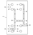
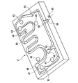
図2には、冷却プレート2の別の実施の形態の平面図が示してある。図1に示した組付け位置において、図2に示した冷却プレート2の側は、特に電動モータ3に接触する側である。図2では、冷却プレート2が冷却通路39を有している。この冷却通路39は溝状に開放している。この冷却通路39に開口しかつ冷却プレート2を貫通する5つの接続通路40〜44が設けられている。さらに、冷却プレート2は5つの接続通路45〜49を有している。これらの接続通路45〜49は冷却プレート2を同じく貫通していて、冷却通路39に対して別個に付与されている。接続通路40〜49は直線状の孔として形成されている。
FIG. 2 shows a plan view of another embodiment of the
電気的なターボチャージャ1の運転時には、冷媒が矢印方向で冷媒流入通路50に流入する。以下、矢印によって冷媒の流れ方向を示す。分岐箇所51では、冷媒の一部が接続通路40に流入する。この接続通路40は、特に電動モータ3への冷却プレート2の当付けによる組付け位置において、有利にはステータ10に通じる接続通路に接続されている。冷媒のその他の部分は分岐箇所51から分岐箇所52にまで流れる。そこから、冷媒の一部が接続通路41に流れる。この接続通路41は、特に組付け位置において、軸12の軸受け34;33に通じる接続通路に接続されている。冷媒の一部は分岐箇所52から分岐箇所53に流れる。そこから、冷媒の一部が接続通路42に流れる。この場合、組付け位置では、接続通路42が、有利にはステータ10に通じる接続通路に接続されている。冷媒のその他の部分は分岐箇所53から分岐箇所54に流れる。この分岐箇所54から、冷媒の一部が接続通路43に流れる。この接続通路43は、組付け位置において、特に軸12の軸受け33;34に通じる接続通路に接続されている。冷媒のその他の部分は分岐箇所54から接続通路44に流れ、次いで、冷却プレート2を貫いて、この冷却プレート2の反対の側に流れる。特にステータ10の冷却後、冷媒は、接続通路46,49を通って冷却プレート2を貫いて冷却プレート2の反対の側に流れ、特に軸受け33;34の冷却後、冷媒は接続通路45を通って冷却プレート2の反対の側に流れ、特に軸受け34;33の冷却後、冷媒は接続通路47を通って冷却プレート2の反対の側に流れる。接続通路48は、組付け位置において、特に電動モータ3の分割ケーシング7によって、図2に示した側で閉鎖される。
During operation of the
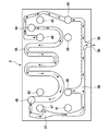
図3には、図2と同じ実施の形態における冷却プレート2の、図2と反対の側の平面図が示してある。図3に示した冷却プレート2の面は、接続通路40〜49に対して付加的に、溝状に形成された冷却通路55と、冷媒流出通路56とを有している。
FIG. 3 is a plan view of the
電気的なターボチャージャ1の運転時には、冷媒が、図2に示した冷却プレート2の側から接続通路44を通って、図3に示した冷却プレート2の側に流れる。図1に示した組付け位置では、特に出力電子装置6への冷却プレート2の当付けによって、接続通路44が、出力電子装置6内に延びる接続通路28に接続されている。冷媒の一部が接続通路28を通って流れ、冷媒のその他の部分は冷却通路55を通って流れる。冷媒は部分的にメアンダ状に冷却通路55を通って流れ、したがって、特に出力電子装置6への冷却プレート2の当付けによって、出力電子装置6を接触により冷却する。接続通路48は、組付け位置において、特に流体技術的に接続通路28に接続されている。したがって、接続通路48、特に出力電子装置6から、冷媒が冷却通路55に流入する。接続通路48から、冷媒は分岐箇所57に流れる。この分岐箇所57では、付加的な冷媒が、組付け位置において、接続通路47、特に軸受け34;33から到来して冷却通路55に流入する。分岐箇所58では、付加的な冷媒が、組付け位置において、接続通路46、特にステータ10から到来して冷却通路55に流入する。分岐箇所58から、冷媒は分岐箇所59に流れ、そこから、冷媒流出通路56に流れる。この冷媒流出通路56を通って、冷媒は冷却プレート2から流出する。接続通路49を通って、冷媒は、組付け位置において、特にステータ10から到来して冷却通路55に流入し、接続通路45を通って、付加的な冷媒が、組付け位置において、特に軸受け33;34から到来して冷却通路55に流入し、分岐箇所59で冷媒が冷媒流出通路56に流入し、その後、冷却プレート2から流出する。
When the
図3に示した冷却プレート2の側における接続通路40〜43の開口は、組付け位置において、特に出力電子装置6への冷却プレート2の当付けによって閉鎖されている。
The openings of the
接続通路40〜49と、ここには図示していない接続通路とにおける調整された流れが可能となる。なぜならば、図2に示した冷却プレート2の側では、有利には水である冷媒の圧力が、図3に示した冷却プレート2の側における圧力よりも大きいからである。
A regulated flow is possible in the
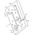
図4および図5には、図2および図3に示した冷却プレート2の実施の形態が示してある。この場合、図4および図5に示した等測図は、冷却プレート2の構造をより容易に理解するために役立つ。
4 and 5 show an embodiment of the
1 ターボチャージャ
2 冷却プレート
3 電動モータ
4 コンプレッサ
5 タービン
6 出力電子装置
7 分割ケーシング
8 外側分割ケーシング
9 内側分割ケーシング
10 ステータ
11 ロータ
12 軸
13 分割ケーシング
14 コンプレッサホイール
15 分割ケーシング
16 タービンホイール
17 分割ケーシング
18 冷媒流入通路
19 冷却通路
20 接続通路
21 接続通路
22 接続通路
23 接続通路
24 接続通路
25 接続通路
26 接続通路
27 接続通路
28 接続通路
29 冷却螺線通路
30 冷却室
31 冷却螺線通路
32 冷却螺線通路
33 軸受け
34 軸受け
35 シール部材
36 シール部材
37 巻付けヘッド
38 巻付けヘッド
39 冷却通路
40 接続通路
41 接続通路
42 接続通路
43 接続通路
44 接続通路
45 接続通路
46 接続通路
47 接続通路
48 接続通路
49 接続通路
50 冷媒流入通路
51 分岐箇所
52 分岐箇所
53 分岐箇所
54 分岐箇所
55 冷却通路
56 冷媒流出通路
57 分岐箇所
58 分岐箇所
59 分岐箇所
DESCRIPTION OF
Claims (14)
Applications Claiming Priority (2)
| Application Number | Priority Date | Filing Date | Title |
|---|---|---|---|
| DE102009044921A DE102009044921A1 (en) | 2009-09-23 | 2009-09-23 | Electric turbocharger |
| DE102009044921.3 | 2009-09-23 |
Publications (2)
| Publication Number | Publication Date |
|---|---|
| JP2011069367A true JP2011069367A (en) | 2011-04-07 |
| JP5911191B2 JP5911191B2 (en) | 2016-04-27 |
Family
ID=43513845
Family Applications (1)
| Application Number | Title | Priority Date | Filing Date |
|---|---|---|---|
| JP2010212170A Active JP5911191B2 (en) | 2009-09-23 | 2010-09-22 | Electric turbocharger |
Country Status (3)
| Country | Link |
|---|---|
| EP (1) | EP2305981B1 (en) |
| JP (1) | JP5911191B2 (en) |
| DE (1) | DE102009044921A1 (en) |
Cited By (4)
| Publication number | Priority date | Publication date | Assignee | Title |
|---|---|---|---|---|
| WO2013002147A1 (en) * | 2011-06-30 | 2013-01-03 | 三菱重工業株式会社 | Cooling structure for bearing housing for turbocharger |
| CN107250505A (en) * | 2015-02-27 | 2017-10-13 | 罗伯特·博世有限公司 | Supercharger, in particular exhaust gas turbocharger, for drive unit and corresponding drive unit |
| JP2017203407A (en) * | 2016-05-11 | 2017-11-16 | 株式会社マーレ フィルターシステムズ | Turbocharger |
| EP4112902A1 (en) * | 2021-06-28 | 2023-01-04 | Garrett Transportation I Inc. | Coolant system for integrated e-machine controller for turbomachine |
Families Citing this family (13)
| Publication number | Priority date | Publication date | Assignee | Title |
|---|---|---|---|---|
| ES2706421T3 (en) * | 2011-07-04 | 2019-03-28 | Iveco Spa | Supercharger for an industrial vehicle with improved connection characteristics to the refrigeration circuit and the industrial vehicle comprising such a supercharger |
| DE102011087601A1 (en) * | 2011-12-01 | 2013-06-06 | Robert Bosch Gmbh | Turbo compressor, fuel cell system |
| FR3045723B1 (en) * | 2015-12-18 | 2019-12-13 | Valeo Systemes De Controle Moteur | ELECTRIC COMPRESSOR |
| FR3048034B1 (en) * | 2016-02-21 | 2020-03-20 | Valeo Systemes De Controle Moteur | ELECTRIC COMPRESSOR |
| FR3064840B1 (en) | 2017-04-03 | 2019-12-27 | Mmt ag | THERMOREGULATED HIGH POWER ELECTRIC MACHINE |
| US10598084B2 (en) * | 2018-03-14 | 2020-03-24 | Borgwarner Inc. | Cooling and lubrication system for a turbocharger |
| DE102019004250A1 (en) * | 2019-06-14 | 2020-12-17 | Daimler Ag | Turbo machine, in particular exhaust gas turbocharger, for a motor vehicle and motor vehicle |
| CN213305843U (en) | 2019-09-23 | 2021-05-28 | 博格华纳公司 | Power electronics assembly for controlling electrically actuated turbocharger |
| GB202002218D0 (en) * | 2020-02-18 | 2020-04-01 | Bowman Power Group Ltd | Electric Turbomachines |
| US11781565B2 (en) | 2021-06-28 | 2023-10-10 | Garrett Transportation I Inc. | Integrated e-machine controller for turbomachine having fastener arrangement for electronics components |
| US12132376B2 (en) | 2021-06-28 | 2024-10-29 | Garrett Transportation I Inc. | Integrated e-machine controller for turbomachine having fastening arrangement |
| US12082360B2 (en) | 2021-09-10 | 2024-09-03 | Garrett Transportation I Inc | Resilient printed circuit board retention arrangement |
| US11655734B1 (en) | 2021-12-09 | 2023-05-23 | Garrett Transportation I Inc | Integrated e-machine controller for turbomachine with thermally de-coupled fastener arrangement |
Citations (4)
| Publication number | Priority date | Publication date | Assignee | Title |
|---|---|---|---|---|
| JPS5151633A (en) * | 1974-09-09 | 1976-05-07 | Borg Warner | |
| JPH01102461U (en) * | 1987-12-26 | 1989-07-11 | ||
| JP2002186222A (en) * | 2000-12-18 | 2002-06-28 | Mitsubishi Electric Corp | Control device integrated motor and vehicle equipped with it |
| JP2005120927A (en) * | 2003-10-17 | 2005-05-12 | Toyota Motor Corp | Supercharger with rotating electric machine having a cylindrical member extending between bearings |
Family Cites Families (5)
| Publication number | Priority date | Publication date | Assignee | Title |
|---|---|---|---|---|
| DE10063321A1 (en) * | 2000-12-19 | 2002-06-20 | Gfas Mbh Ges Fuer Aufladetechn | Electrically driven flow compressor |
| US7063519B2 (en) * | 2002-07-02 | 2006-06-20 | R & D Dynamics Corporation | Motor driven centrifugal compressor/blower |
| CN101793268B (en) * | 2005-06-06 | 2013-05-08 | 格布尔·贝克尔有限责任公司 | Radial fan |
| JP4692820B2 (en) * | 2005-08-11 | 2011-06-01 | 株式会社Ihi | Supercharger with electric motor |
| DE102005057308A1 (en) * | 2005-12-01 | 2007-06-14 | Bayerische Motoren Werke Ag | Internal combustion (IC) engine with turbocharger for motor vehicle, connects electric motor housing to intake air suction line in manner in which motor and/or electronic controls can be cooled with part of intake air |
-
2009
- 2009-09-23 DE DE102009044921A patent/DE102009044921A1/en not_active Withdrawn
-
2010
- 2010-08-06 EP EP10172144A patent/EP2305981B1/en active Active
- 2010-09-22 JP JP2010212170A patent/JP5911191B2/en active Active
Patent Citations (4)
| Publication number | Priority date | Publication date | Assignee | Title |
|---|---|---|---|---|
| JPS5151633A (en) * | 1974-09-09 | 1976-05-07 | Borg Warner | |
| JPH01102461U (en) * | 1987-12-26 | 1989-07-11 | ||
| JP2002186222A (en) * | 2000-12-18 | 2002-06-28 | Mitsubishi Electric Corp | Control device integrated motor and vehicle equipped with it |
| JP2005120927A (en) * | 2003-10-17 | 2005-05-12 | Toyota Motor Corp | Supercharger with rotating electric machine having a cylindrical member extending between bearings |
Cited By (6)
| Publication number | Priority date | Publication date | Assignee | Title |
|---|---|---|---|---|
| WO2013002147A1 (en) * | 2011-06-30 | 2013-01-03 | 三菱重工業株式会社 | Cooling structure for bearing housing for turbocharger |
| JP2013011253A (en) * | 2011-06-30 | 2013-01-17 | Mitsubishi Heavy Ind Ltd | Cooling structure for bearing housing for turbocharger |
| US9546568B2 (en) | 2011-06-30 | 2017-01-17 | Mitsubishi Heavy Industries, Ltd. | Cooling structure of bearing housing for turbocharger |
| CN107250505A (en) * | 2015-02-27 | 2017-10-13 | 罗伯特·博世有限公司 | Supercharger, in particular exhaust gas turbocharger, for drive unit and corresponding drive unit |
| JP2017203407A (en) * | 2016-05-11 | 2017-11-16 | 株式会社マーレ フィルターシステムズ | Turbocharger |
| EP4112902A1 (en) * | 2021-06-28 | 2023-01-04 | Garrett Transportation I Inc. | Coolant system for integrated e-machine controller for turbomachine |
Also Published As
| Publication number | Publication date |
|---|---|
| DE102009044921A1 (en) | 2011-04-07 |
| EP2305981B1 (en) | 2013-04-03 |
| EP2305981A1 (en) | 2011-04-06 |
| JP5911191B2 (en) | 2016-04-27 |
Similar Documents
| Publication | Publication Date | Title |
|---|---|---|
| JP5911191B2 (en) | Electric turbocharger | |
| JP5935894B2 (en) | Electric motor cooling structure | |
| JP6930599B2 (en) | Centrifugal compressor | |
| KR102318180B1 (en) | Fluid compressor | |
| KR102823465B1 (en) | Method of making an axial flux motor water pump and its rotor | |
| TW201832452A (en) | Motor cooling structure, power motor and electric drive system | |
| US10450948B2 (en) | Charger, in particular an exhaust gas turbo charger, for a drive device and corresponding drive device | |
| JP5631350B2 (en) | Compressor | |
| CN102751819A (en) | Novel water cooling structure of water pump motor | |
| KR102400801B1 (en) | Electric centrifugal compressor | |
| CN105471131B (en) | Cooling mechanism for stator in oil immersed motor | |
| US10378555B2 (en) | Electric compressor for use in a motor vehicle having a housing with an inner circumferential recess closed by a control unit to form a cooling duct | |
| CN207652150U (en) | The field frame assembly of drive motor for vehicle | |
| JP2005016508A (en) | Electric pump device for fluid | |
| JP2008295192A (en) | Rotating electric machine | |
| JP2005036664A (en) | Compressor, turbo-charger, and fuel cell | |
| JP5699541B2 (en) | Electric assist turbocharger cooling system | |
| KR20240001196A (en) | gas supply device | |
| JP5691406B2 (en) | Electric assist turbocharger cooling device | |
| JP5760387B2 (en) | Electric assist turbocharger cooling device | |
| CN105684275A (en) | Fan directing element for an electric machine | |
| CN107842501A (en) | Compressor | |
| JP2017145724A (en) | Motor compressor | |
| JP5903760B2 (en) | Electric assist turbocharger cooling device | |
| CN119315752A (en) | Automobile drive motor with cooling oil circuit structure and cooling method thereof |
Legal Events
| Date | Code | Title | Description |
|---|---|---|---|
| A621 | Written request for application examination |
Free format text: JAPANESE INTERMEDIATE CODE: A621 Effective date: 20130919 |
|
| A977 | Report on retrieval |
Free format text: JAPANESE INTERMEDIATE CODE: A971007 Effective date: 20140515 |
|
| A131 | Notification of reasons for refusal |
Free format text: JAPANESE INTERMEDIATE CODE: A131 Effective date: 20140526 |
|
| A521 | Request for written amendment filed |
Free format text: JAPANESE INTERMEDIATE CODE: A523 Effective date: 20140821 |
|
| A02 | Decision of refusal |
Free format text: JAPANESE INTERMEDIATE CODE: A02 Effective date: 20140916 |
|
| A521 | Request for written amendment filed |
Free format text: JAPANESE INTERMEDIATE CODE: A523 Effective date: 20150108 |
|
| A911 | Transfer to examiner for re-examination before appeal (zenchi) |
Free format text: JAPANESE INTERMEDIATE CODE: A911 Effective date: 20150115 |
|
| A912 | Re-examination (zenchi) completed and case transferred to appeal board |
Free format text: JAPANESE INTERMEDIATE CODE: A912 Effective date: 20150306 |
|
| A521 | Request for written amendment filed |
Free format text: JAPANESE INTERMEDIATE CODE: A523 Effective date: 20160112 |
|
| A61 | First payment of annual fees (during grant procedure) |
Free format text: JAPANESE INTERMEDIATE CODE: A61 Effective date: 20160329 |
|
| R150 | Certificate of patent or registration of utility model |
Ref document number: 5911191 Country of ref document: JP Free format text: JAPANESE INTERMEDIATE CODE: R150 |
|
| R250 | Receipt of annual fees |
Free format text: JAPANESE INTERMEDIATE CODE: R250 |
|
| R250 | Receipt of annual fees |
Free format text: JAPANESE INTERMEDIATE CODE: R250 |
|
| R250 | Receipt of annual fees |
Free format text: JAPANESE INTERMEDIATE CODE: R250 |
|
| R250 | Receipt of annual fees |
Free format text: JAPANESE INTERMEDIATE CODE: R250 |
|
| R250 | Receipt of annual fees |
Free format text: JAPANESE INTERMEDIATE CODE: R250 |
|
| R250 | Receipt of annual fees |
Free format text: JAPANESE INTERMEDIATE CODE: R250 |
|
| R250 | Receipt of annual fees |
Free format text: JAPANESE INTERMEDIATE CODE: R250 |