JP2011069352A - Temperature detection in gas turbine - Google Patents
Temperature detection in gas turbine Download PDFInfo
- Publication number
- JP2011069352A JP2011069352A JP2010164414A JP2010164414A JP2011069352A JP 2011069352 A JP2011069352 A JP 2011069352A JP 2010164414 A JP2010164414 A JP 2010164414A JP 2010164414 A JP2010164414 A JP 2010164414A JP 2011069352 A JP2011069352 A JP 2011069352A
- Authority
- JP
- Japan
- Prior art keywords
- metal
- wires
- temperature
- temperature detector
- detecting
- Prior art date
- Legal status (The legal status is an assumption and is not a legal conclusion. Google has not performed a legal analysis and makes no representation as to the accuracy of the status listed.)
- Ceased
Links
Images

Classifications
-
- F—MECHANICAL ENGINEERING; LIGHTING; HEATING; WEAPONS; BLASTING
- F01—MACHINES OR ENGINES IN GENERAL; ENGINE PLANTS IN GENERAL; STEAM ENGINES
- F01D—NON-POSITIVE DISPLACEMENT MACHINES OR ENGINES, e.g. STEAM TURBINES
- F01D17/00—Regulating or controlling by varying flow
- F01D17/02—Arrangement of sensing elements
- F01D17/08—Arrangement of sensing elements responsive to condition of working-fluid, e.g. pressure
- F01D17/085—Arrangement of sensing elements responsive to condition of working-fluid, e.g. pressure to temperature
-
- G—PHYSICS
- G01—MEASURING; TESTING
- G01K—MEASURING TEMPERATURE; MEASURING QUANTITY OF HEAT; THERMALLY-SENSITIVE ELEMENTS NOT OTHERWISE PROVIDED FOR
- G01K13/00—Thermometers specially adapted for specific purposes
- G01K13/02—Thermometers specially adapted for specific purposes for measuring temperature of moving fluids or granular materials capable of flow
-
- G—PHYSICS
- G01—MEASURING; TESTING
- G01K—MEASURING TEMPERATURE; MEASURING QUANTITY OF HEAT; THERMALLY-SENSITIVE ELEMENTS NOT OTHERWISE PROVIDED FOR
- G01K3/00—Thermometers giving results other than momentary value of temperature
- G01K3/08—Thermometers giving results other than momentary value of temperature giving differences of values; giving differentiated values
- G01K3/10—Thermometers giving results other than momentary value of temperature giving differences of values; giving differentiated values in respect of time, e.g. reacting only to a quick change of temperature
-
- G—PHYSICS
- G01—MEASURING; TESTING
- G01K—MEASURING TEMPERATURE; MEASURING QUANTITY OF HEAT; THERMALLY-SENSITIVE ELEMENTS NOT OTHERWISE PROVIDED FOR
- G01K7/00—Measuring temperature based on the use of electric or magnetic elements directly sensitive to heat ; Power supply therefor, e.g. using thermoelectric elements
- G01K7/02—Measuring temperature based on the use of electric or magnetic elements directly sensitive to heat ; Power supply therefor, e.g. using thermoelectric elements using thermoelectric elements, e.g. thermocouples
-
- G—PHYSICS
- G01—MEASURING; TESTING
- G01K—MEASURING TEMPERATURE; MEASURING QUANTITY OF HEAT; THERMALLY-SENSITIVE ELEMENTS NOT OTHERWISE PROVIDED FOR
- G01K7/00—Measuring temperature based on the use of electric or magnetic elements directly sensitive to heat ; Power supply therefor, e.g. using thermoelectric elements
- G01K7/16—Measuring temperature based on the use of electric or magnetic elements directly sensitive to heat ; Power supply therefor, e.g. using thermoelectric elements using resistive elements
-
- G—PHYSICS
- G01—MEASURING; TESTING
- G01K—MEASURING TEMPERATURE; MEASURING QUANTITY OF HEAT; THERMALLY-SENSITIVE ELEMENTS NOT OTHERWISE PROVIDED FOR
- G01K2205/00—Application of thermometers in motors, e.g. of a vehicle
- G01K2205/04—Application of thermometers in motors, e.g. of a vehicle for measuring exhaust gas temperature
Landscapes
- Physics & Mathematics (AREA)
- General Physics & Mathematics (AREA)
- Engineering & Computer Science (AREA)
- Mechanical Engineering (AREA)
- General Engineering & Computer Science (AREA)
- Measuring Temperature Or Quantity Of Heat (AREA)
- Control Of Combustion (AREA)
- Control Of Turbines (AREA)
- Investigating Or Analyzing Materials By The Use Of Electric Means (AREA)
Abstract
【課題】ガスタービンにおける温度検出器及び温度検出方法を提供する。
【解決手段】本温度検出器(10)は、第1の金属(4)と該第1の金属とは異なる第2の金属(6)とを含む。第1の金属は、複数のワイヤを含み、また第2の金属は、ワイヤを含む。第1の金属の複数のワイヤは、並列接合部(8)として第2の金属のワイヤに接続される。別の温度検出器は、複数の抵抗温度検出器を含む。複数の抵抗温度検出器は、複数の接合部において接続される。タービンの部品(12)の温度変化を検出する本方法は、複数の接合部において互いに接続されかつ該部品と接触状態になった第1の金属及び該第1の金属とは異なる第2の金属を備えた温度検出器を準備するステップと、任意の接合部において任意の電圧変化を検出するステップとを含む。
【選択図】 図3A temperature detector and a temperature detection method in a gas turbine are provided.
The temperature detector (10) includes a first metal (4) and a second metal (6) different from the first metal. The first metal includes a plurality of wires and the second metal includes wires. The plurality of first metal wires are connected to the second metal wires as parallel joints (8). Another temperature detector includes a plurality of resistance temperature detectors. The plurality of resistance temperature detectors are connected at a plurality of junctions. The method of detecting a temperature change of a turbine component (12) includes a first metal connected to each other at a plurality of joints and in contact with the component, and a second metal different from the first metal. Providing a temperature detector comprising: and detecting any voltage change at any junction.
[Selection] Figure 3
Description
本発明は、ガスタービンエンジンの燃焼器における逆火を検出するための装置及び方法に関する。 The present invention relates to an apparatus and method for detecting flashback in a combustor of a gas turbine engine.
ガスタービン製造業者は通常的に、高効率で作動しかつ望ましくない大気汚染物質排出(エミッション)の発生がより少なくなる新規なガスタービンを作製するための研究及び技術設計プログラムに関与している。従来通りの炭化水素燃料を燃焼させるガスタービンによって通常発生する主な大気汚染物質エミッションは、窒素酸化物、一酸化炭素及び未燃炭化水素である
空気吸入式エンジンにおける窒素分子の酸化は、燃焼システム反応ゾーン内の最高高温ガス温度に大きく依存する。窒素酸化物(NOx)を形成する化学反応速度は、温度の関数である。燃焼室高温ガスの温度を十分に低いレベルに制御した場合には、熱NOxが減少することになる。
Gas turbine manufacturers are typically involved in research and engineering design programs to create new gas turbines that operate with high efficiency and produce less unwanted air pollutant emissions. The main air pollutant emissions normally generated by gas turbines burning conventional hydrocarbon fuels are nitrogen oxides, carbon monoxide and unburned hydrocarbons. Highly dependent on the highest hot gas temperature in the reaction zone. The chemical reaction rate to form nitrogen oxides (NOx) is a function of temperature. When the temperature of the combustion chamber hot gas is controlled to a sufficiently low level, the thermal NOx decreases.
燃焼器の反応ゾーンの温度を熱NOxが形成されるレベル以下に制御する1つの方法は、燃焼に先立って燃料及び空気を予混合して希薄混合気にすることである。希薄予混合燃焼器の燃焼ゾーン内に存在する過剰空気の熱質量は、熱を吸収しかつ燃焼生成物の温度上昇を熱NOxの発生が減少するレベルまで低下させる。 One way to control the temperature of the combustor reaction zone below the level at which hot NOx is formed is to premix fuel and air into a lean mixture prior to combustion. The thermal mass of excess air present in the combustion zone of the lean premix combustor absorbs heat and reduces the temperature rise of the combustion products to a level at which the generation of hot NOx is reduced.
燃料及び空気の希薄予混合で作動する乾式低エミッション燃焼器に関連した幾つかの問題が存在する。燃料及び空気の可燃性混合気が、燃焼器の予混合セクション内に存在し、この予混合セクションは、燃焼器の反応ゾーンの外部に位置している。1つの問題は、逆火により予混合セクション内で燃焼が発生する傾向である。逆火は、燃焼器反応ゾーンから予混合セクション内に火炎が伝播した時に発生する。伴流内部に保持された火炎は、燃料噴射コラム(ジェット直交流)又はベーン後縁の背後に流れる。 There are several problems associated with dry low emission combustors operating with lean premixing of fuel and air. A combustible mixture of fuel and air is present in the premixing section of the combustor, which is located outside the reaction zone of the combustor. One problem is the tendency for combustion to occur in the premix section due to flashback. Backfire occurs when a flame propagates from the combustor reaction zone into the premix section. The flame held inside the wake flows behind the fuel injection column (jet cross flow) or the vane trailing edge.
別の問題は、自己着火である。自己着火は、予混合セクション内の燃料/空気混合気におけるドウェル時間及び温度が点火器なしで燃焼を開始するのに十分となった時に発生する。予混合セクション内での燃焼の結果として、エミッション性能の低下を生じ、また/或いは一般的に燃焼の熱に耐えるように設計されていない予混合セクションに対する過加熱及び損傷が生じる。 Another problem is self-ignition. Autoignition occurs when the dwell time and temperature in the fuel / air mixture in the premix section is sufficient to initiate combustion without an igniter. As a result of combustion in the premix section, there is a reduction in emissions performance and / or overheating and damage to the premix section that is not typically designed to withstand the heat of combustion.
従って、解決すべき問題は、予混合セクション内で燃焼を引き起こす逆火、保炎及び/又は自己着火を防止することである。逆火、保炎及び/又は自己着火の懸案は、より反応性がある燃料の使用により高まるので、信頼性がある逆火検出方法に対する必要性が増大する。 Therefore, the problem to be solved is to prevent flashback, flame holding and / or autoignition that cause combustion in the premix section. Since the concerns of flashback, flame holding and / or autoignition are increased by the use of more reactive fuels, the need for a reliable flashback detection method increases.
1つの実例実施形態では、温度検出器は、第1の金属と該第1の金属とは異なる第2の金属とを含む。第1の金属は、複数のワイヤを含み、また第2の金属は、ワイヤを含む。第1の金属の複数のワイヤは、並列接合部として第2の金属のワイヤに接続される。 In one example embodiment, the temperature detector includes a first metal and a second metal that is different from the first metal. The first metal includes a plurality of wires and the second metal includes wires. The plurality of first metal wires are connected to the second metal wires as parallel joints.
別の実例実施形態では、温度検出器は、複数の抵抗温度検出器を含む。複数の抵抗温度検出器は、複数の接合部において接続される。 In another example embodiment, the temperature detector includes a plurality of resistance temperature detectors. The plurality of resistance temperature detectors are connected at a plurality of junctions.
さらに別の実例実施形態では、タービンの部品の温度変化を検出する方法は、複数の接合部において互いに接続されかつ該部品と接触状態になった第1の金属及び該第1の金属とは異なる第2の金属を備えた温度検出器を準備するステップと、任意の接合部において任意の電圧変化を検出するステップとを含む。 In yet another example embodiment, a method for detecting temperature changes in a turbine component is different from the first metal connected to and in contact with the components at a plurality of joints. Providing a temperature detector with a second metal and detecting any voltage change at any junction.
さらに別の実例実施形態では、タービンの部品における温度を検出する方法は、1以上のワイヤの抵抗の変化によって或いは1以上のワイヤの断線によって生じた該1以上のワイヤを通る電流又はパルス信号における変化を検出するステップを含む。 In yet another illustrative embodiment, a method of detecting temperature in a turbine component is in a current or pulse signal through the one or more wires caused by a change in resistance of one or more wires or by a break in one or more wires. Detecting a change.
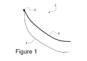
図1を参照すると、熱電対2は、1つの位置又は接合部8において接合された2つの異種金属4、6を含む。ゼーベック効果により、接合部8(図1)における温度の関数として、電圧が発生する。
Referring to FIG. 1, the
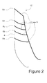
逆火検出(又は、検出すべき他の温度関連過渡信号)の場合に、火炎の正確な温度を測定することは、必要でない。逆火は、ガスタービン内の燃焼関連部品の複数位置において温度過渡信号を検出することによって検出して、それらの位置の任意の位置において温度が上昇した場合には何時でも作動を迅速に停止させることができるようにすることができる。図2を参照すると、並列熱電対接合部8a〜8eを備えた熱電対ネット(網)10が、2つの異種金属4、6によって形成される。熱電対ネット10は、該ネット10上の接合部8a〜8eのいずれかが温度変化、例えば温度上昇を受けた場合に、電圧変化を示す。
In the case of flashback detection (or other temperature related transient signal to be detected), it is not necessary to measure the exact temperature of the flame. Backfire is detected by detecting temperature transient signals at multiple locations of combustion-related components in the gas turbine, and quickly stops operation whenever the temperature rises at any of those locations Can be able to. Referring to FIG. 2, a
火炎事象において、火炎が接合部8a近くにある場合には、接合部8aは、正確なつまり最高の温度変化を測定することになる。火炎が接合部8e近くにある場合には、接合部8eは、より低い温度変化を測定することになるが、火炎がそれが発生すべきではない場所で発生しているかどうかを示すことになる変化を検出することになる。接合部8b〜8d近くの火炎は、接合部8aと接合部8eとの間の温度の変化を示すことになる。
In a flame event, if the flame is near the
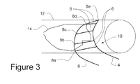
図3を参照すると、ネット10は、例えばバーナチューブ、キャップ又はライナなどのガスタービンの部品12上に配置して、それが発生するあらゆる場所における温度偏差を検出することができる。複数位置で発生する可能性がある逆火火炎14は、ネット10及び単一のモニタ(図示せず)によって検出することができる。
Referring to FIG. 3, the
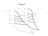
図4を参照すると、並列接合部8a〜8eの複数のネットは、互いに連結して、完成ネット16を形成することができる。ネット16は、単一のモニタ(図示せず)に接続することができる。モニタは、最も強い信号を読取って、ネット16上の任意の接合部における温度上昇を検出することになるようにすることになる。これにより、ハードウェアの大きな領域にわたり単一のモニタで検出することが可能になる。
Referring to FIG. 4, the plurality of nets of the
別の実施形態は、図5に示すように部品12の周りに螺旋状に巻いた連続抵抗温度検出器(RTD)又はワイヤ18を含むことができ、この連続抵抗温度検出器(RTD)又はワイヤ18は次に、該RTD又はワイヤ18に対する抵抗率変化を測定することによって、例えば逆火火炎14により生じた該RTD又はワイヤ18に沿ったあらゆる場所における温度変化を検出することができる。それに代えて、温度変化は、RTD又はワイヤ18によりもたらされたパルス信号の周波数における変化を検出することによって検出することができる。前述した1つ又は複数のネットと同様に、1つ又は複数のRTDのネットを使用することができることを理解されたい。例えば、第1のRTDは、第1の材料の複数のRTD素子を含むことができ、これら第1の材料の複数のRTD素子は、並列接合部として第2の材料の第2のRTD素子に接続することができる。
Another embodiment may include a continuous resistance temperature detector (RTD) or
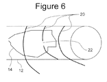
図6を参照すると、別の実例実施形態では、部品12の周りに低融点ワイヤ20を螺旋状に巻くことができる。温度の上昇は、低融点ワイヤ20に参照符号22における破損開放部を生じさせて、低耐熱性ワイヤ20を通しての信号の喪失に注目することによって温度上昇を検出することができるようにすることができる。
Referring to FIG. 6, in another example embodiment, a low
直列にした及び/又は並列にした熱電対接合部或いはRTD接合部の1つ又は複数のネットの使用により、部品損傷のリスクを減少させかつ/又はリスクを軽減させる方法を可能にすることによってガスタービンの作動性能を高めるのを可能にすることができる。直列にした及び/又は並列にした熱電対接合部或いはRTD接合部の1つ又は複数のネットの使用により、複数センサを必要としない高い信頼性の逆火検出方法を得ることができる。 Gas by allowing one or more nets of serial and / or parallel thermocouple junctions or RTD junctions to reduce and / or reduce the risk of component damage It may be possible to enhance the operational performance of the turbine. The use of one or more nets of thermocouple junctions or RTD junctions in series and / or in parallel can provide a reliable flashback detection method that does not require multiple sensors.
熱電対接合部及び/又はRTD接合部の1つ又は複数のネットは、燃焼ノズル、バーナチューブ、キャップ或いはライナで使用して、あらゆる温度偏差を検出しかつ該温度偏差に応答するのを可能にすることができる。熱電対接合部及び/又はRTD接合部の1つ又は複数のネットはまた、大きな温度偏差が懸案であるあらゆるその他の部品又は製品において使用することができる。 One or more nets of thermocouple junctions and / or RTD junctions can be used with combustion nozzles, burner tubes, caps or liners to detect and respond to any temperature deviations can do. One or more nets of thermocouple junctions and / or RTD junctions can also be used in any other component or product where large temperature deviations are a concern.
現時点で最も実用的かつ好ましい実施形態であると考えられるものに関して本発明を説明してきたが、本発明が開示した実施形態に限定されるべきものではなく、逆に、特許請求の範囲の技術思想及び技術的範囲内に含まれる様々な変更及び均等な構成を保護しようとするものであることを理解されたい。 Although the present invention has been described with respect to what is considered to be the most practical and preferred embodiments at the present time, the present invention should not be limited to the disclosed embodiments, and conversely, the technical ideas of the claims It should be understood that various modifications and equivalent arrangements included within the technical scope are intended to be protected.
2 熱電対
4 第1の金属
6 第2の金属
8 接合部
10 熱電対ネット
12 バンパチューブ、キャップ、ライナ
14 逆火火炎
16 熱電対ネット
18 抵抗温度検出器
20 低温ワイヤ
22 破損開放部
2
Claims (12)
第1の金属(4)と、
前記第1の金属とは異なる第2の金属(6)と
を備えており、
前記第1の金属が複数のワイヤを含みまた前記第2の金属がワイヤを含み、
前記第1の金属の複数のワイヤが、並列接合部(8)として前記第2の金属のワイヤに接続される、
温度検出器。 A temperature detector (10),
A first metal (4);
A second metal (6) different from the first metal,
The first metal includes a plurality of wires and the second metal includes a wire;
A plurality of wires of the first metal are connected to the second metal wires as parallel joints (8);
Temperature detector.
前記複数の抵抗温度検出器が複数の接合部において接続される、温度検出器。 A temperature detector including a plurality of resistance temperature detectors,
A temperature detector, wherein the plurality of resistance temperature detectors are connected at a plurality of junctions.
前記第1の材料の複数の抵抗温度検出器が、並列接合部として前記第2の材料の抵抗温度検出器に接続される、
請求項3記載の温度検出器。 The plurality of resistance temperature detectors includes a plurality of resistance temperature detectors of a first material and a second resistance temperature detector of a second material different from the first material;
A plurality of resistance temperature detectors of the first material are connected as parallel junctions to the resistance temperature detector of the second material;
The temperature detector according to claim 3.
複数の接合部(8)において互いに接続されかつ前記部品と接触状態になった第1の金属(4)及び該第1の金属とは異なる第2の金属(6)を備えた温度検出器(10)を準備するステップと、
任意の接合部において任意の電圧変化を検出するステップと
を含む方法。 A method for detecting a temperature change in a turbine component (12) comprising:
A temperature detector comprising a first metal (4) connected to each other and in contact with the component at a plurality of joints (8) and a second metal (6) different from the first metal ( 10) preparing steps;
Detecting any voltage change at any junction.
前記第1の金属の1以上のワイヤが、並列接合部として前記第2の金属の1以上のワイヤに接続される、請求項6記載の方法。 The first metal includes one or more wires and the second metal includes one or more wires;
The method of claim 6, wherein the one or more wires of the first metal are connected to the one or more wires of the second metal as parallel junctions.
1以上のワイヤ(18)の抵抗の変化によって或いは1以上のワイヤ(20)の断線によって生じた該1以上のワイヤ(18、20)を通る電流又はパルス信号における変化を検出するステップを
含む方法。 A method for detecting temperature in a turbine component comprising:
Detecting a change in current or pulse signal through the one or more wires (18, 20) caused by a change in resistance of the one or more wires (18) or by a break in the one or more wires (20). .
Applications Claiming Priority (1)
| Application Number | Priority Date | Filing Date | Title |
|---|---|---|---|
| US12/568,348 US8334749B1 (en) | 2009-09-28 | 2009-09-28 | Temperature detection in a gas turbine |
Publications (2)
| Publication Number | Publication Date |
|---|---|
| JP2011069352A true JP2011069352A (en) | 2011-04-07 |
| JP2011069352A5 JP2011069352A5 (en) | 2013-05-02 |
Family
ID=43705819
Family Applications (1)
| Application Number | Title | Priority Date | Filing Date |
|---|---|---|---|
| JP2010164414A Ceased JP2011069352A (en) | 2009-09-28 | 2010-07-22 | Temperature detection in gas turbine |
Country Status (5)
| Country | Link |
|---|---|
| US (1) | US8334749B1 (en) |
| JP (1) | JP2011069352A (en) |
| CN (1) | CN102032952A (en) |
| CH (1) | CH701849A2 (en) |
| DE (1) | DE102010036526A1 (en) |
Families Citing this family (2)
| Publication number | Priority date | Publication date | Assignee | Title |
|---|---|---|---|---|
| CN104019926A (en) * | 2014-06-13 | 2014-09-03 | 四川亚美动力技术有限公司 | Thermocouple matching box for detecting temperature between turbines of engine |
| CN114705312B (en) * | 2022-06-01 | 2022-09-02 | 中北大学 | Turbine blade surface temperature measuring method |
Citations (2)
| Publication number | Priority date | Publication date | Assignee | Title |
|---|---|---|---|---|
| JPH10317991A (en) * | 1997-05-15 | 1998-12-02 | Hitachi Ltd | gas turbine |
| JP2003057120A (en) * | 2001-08-10 | 2003-02-26 | Fujikura Ltd | Multi-point temperature measuring device |
Family Cites Families (22)
| Publication number | Priority date | Publication date | Assignee | Title |
|---|---|---|---|---|
| US3690974A (en) * | 1968-12-17 | 1972-09-12 | Toshinobu Kawazoe | Method for manufacturing a temperature detecting wire |
| US3966500A (en) * | 1973-04-25 | 1976-06-29 | Kernforschungsanlage Julich Gesellschaft Mit Beschrankter Haftung | Temperature-measuring device |
| US4228425A (en) * | 1978-02-06 | 1980-10-14 | Afg Industries, Inc. | Tamper-proof transparent security plate |
| US4224461A (en) * | 1978-08-18 | 1980-09-23 | General Electric Company | Ungrounded three wire thermocouple |
| US4490053A (en) * | 1983-04-15 | 1984-12-25 | Lockheed Missiles & Space Company, Inc. | Temperature threshold detector |
| GB9209368D0 (en) * | 1992-04-30 | 1992-06-17 | Wolf Adrian F | A method of making a flexible closure incorporating an alarm system |
| US5592149A (en) * | 1992-07-21 | 1997-01-07 | Alizi; Uri | Security fence |
| CN1081251A (en) * | 1993-05-15 | 1994-01-26 | 李臻 | Ordinary three-wire thermocouple thermometering system |
| US6180867B1 (en) | 1996-04-17 | 2001-01-30 | General Electric Company | Thermal sensor array and methods of fabrication and use |
| US5831511A (en) | 1996-07-11 | 1998-11-03 | General Electric Co. | Resistance temperature detector assembly and method of fabricating same |
| WO1999046823A1 (en) * | 1998-03-10 | 1999-09-16 | Edouard Serras | Method and device for making a plurality of thermocouples, and resulting thermoelectric converter |
| IL126007A (en) * | 1998-08-31 | 2002-07-25 | Hi G Tek Ltd | Electronic filament netting |
| US6213995B1 (en) * | 1999-08-31 | 2001-04-10 | Phelps Dodge High Performance Conductors Of Sc And Ga, Inc. | Flexible tubing with braided signal transmission elements |
| US6352362B2 (en) | 1999-09-14 | 2002-03-05 | General Electric Company | Method of preventing leakage of a fluid along and through an insulating jacket of a thermocouple |
| FR2817617A1 (en) * | 2000-12-01 | 2002-06-07 | Edouard Serras | PROCESS FOR MANUFACTURING THERMOELECTRIC CONVERTERS |
| US7394060B2 (en) * | 2004-05-03 | 2008-07-01 | Tamperproof Container Licensing Corp. | Tamper detection system having plurality of inflatable liner panels with optical couplers |
| GB0421742D0 (en) * | 2004-09-30 | 2004-11-03 | Ncr Int Inc | A penetration screen |
| US7608812B2 (en) * | 2004-11-05 | 2009-10-27 | Tamperproof Container Licensing Corp. | Tamper detection system |
| US7719400B1 (en) * | 2005-08-02 | 2010-05-18 | Rtd Company | Method and apparatus for flexible temperature sensor having coiled element |
| CN101485005A (en) * | 2006-04-24 | 2009-07-15 | 杰森·安德鲁·霍普金斯 | Improvements in thermoelectric generators |
| CN201421377Y (en) * | 2009-04-27 | 2010-03-10 | 绍兴春晖自动化仪表有限公司 | Armored thermocouple with same measuring point and multiple signal outputs |
| CN201440098U (en) * | 2009-07-10 | 2010-04-21 | 武汉钢铁(集团)公司 | Thermocouple with pairs of couple wires |
-
2009
- 2009-09-28 US US12/568,348 patent/US8334749B1/en not_active Expired - Fee Related
-
2010
- 2010-07-20 DE DE102010036526A patent/DE102010036526A1/en not_active Withdrawn
- 2010-07-22 JP JP2010164414A patent/JP2011069352A/en not_active Ceased
- 2010-07-23 CH CH01224/10A patent/CH701849A2/en not_active Application Discontinuation
- 2010-07-28 CN CN2010102464680A patent/CN102032952A/en active Pending
Patent Citations (2)
| Publication number | Priority date | Publication date | Assignee | Title |
|---|---|---|---|---|
| JPH10317991A (en) * | 1997-05-15 | 1998-12-02 | Hitachi Ltd | gas turbine |
| JP2003057120A (en) * | 2001-08-10 | 2003-02-26 | Fujikura Ltd | Multi-point temperature measuring device |
Also Published As
| Publication number | Publication date |
|---|---|
| US8334749B1 (en) | 2012-12-18 |
| DE102010036526A1 (en) | 2011-04-07 |
| CN102032952A (en) | 2011-04-27 |
| CH701849A2 (en) | 2011-03-31 |
Similar Documents
| Publication | Publication Date | Title |
|---|---|---|
| Roy et al. | Experimental study of rotating detonation combustor performance under preheat and back pressure operation | |
| Döbbeling et al. | 25 years of BBC/ABB/Alstom lean premix combustion technologies | |
| JP6262616B2 (en) | Gas turbine combustor | |
| JP4931024B2 (en) | Gas turbine combustor | |
| JP2010101309A (en) | Flame holding tolerant fuel and air premixer for gas turbine combustor | |
| JP5775319B2 (en) | Axial multistage premixed combustion chamber | |
| JP2010159739A (en) | System and method for detecting flame in fuel nozzle of gas turbine | |
| WO1996000364A1 (en) | Pilot injector for gas turbine engines | |
| EP3995741B1 (en) | Torch igniter with cooling system | |
| JP2011208929A (en) | Backfire detecting method of gas turbine combustor | |
| CN101922710A (en) | Burner flashback/flame holding detection by temperature detection | |
| Guo et al. | Combustion and emission performance of swirling-flow single trapped vortex combustor | |
| CN103090415B (en) | Burner and the method being used for supplying fuel to burner | |
| SE531133C2 (en) | Catalytic burner and control procedure | |
| Snyder et al. | Emission and performance of a lean-premixed gas fuel injection system for aeroderivative gas turbine engines | |
| JP2011069352A (en) | Temperature detection in gas turbine | |
| Cerutti et al. | Development Of An Hydrogen Fueled Gas Turbine Combustion System From Conceptual Through Full Scale Verification Test | |
| Ciardiello et al. | Ignition probability and lean ignition behavior of a swirled premixed bluff body stabilized annular combustor | |
| US20220136446A1 (en) | Temperature sensing for torch ignition systems | |
| Roy et al. | Characteristics of a non-premixed rotating detonation combustor using natural gas-hydrogen blend at elevated air-preheat temperature and backpressure | |
| JP3643499B2 (en) | Gas turbine combustion apparatus and flame reverse flow detection method thereof | |
| Xing et al. | Experimental investigation of a single trapped-vortex combustor with a slight temperature raise | |
| Lacy et al. | Temperature detection in a gas turbine | |
| CN106016355A (en) | Ignition device of ejection combustion device | |
| JP7413925B2 (en) | Temperature measuring device and burner |
Legal Events
| Date | Code | Title | Description |
|---|---|---|---|
| A521 | Request for written amendment filed |
Free format text: JAPANESE INTERMEDIATE CODE: A523 Effective date: 20130314 |
|
| A621 | Written request for application examination |
Free format text: JAPANESE INTERMEDIATE CODE: A621 Effective date: 20130314 |
|
| A977 | Report on retrieval |
Free format text: JAPANESE INTERMEDIATE CODE: A971007 Effective date: 20131211 |
|
| A131 | Notification of reasons for refusal |
Free format text: JAPANESE INTERMEDIATE CODE: A131 Effective date: 20131217 |
|
| A521 | Request for written amendment filed |
Free format text: JAPANESE INTERMEDIATE CODE: A523 Effective date: 20140313 |
|
| A01 | Written decision to grant a patent or to grant a registration (utility model) |
Free format text: JAPANESE INTERMEDIATE CODE: A01 Effective date: 20140729 |
|
| A045 | Written measure of dismissal of application [lapsed due to lack of payment] |
Free format text: JAPANESE INTERMEDIATE CODE: A045 Effective date: 20141125 |