JP2011069249A - Rotary compressor - Google Patents
Rotary compressor Download PDFInfo
- Publication number
- JP2011069249A JP2011069249A JP2009219278A JP2009219278A JP2011069249A JP 2011069249 A JP2011069249 A JP 2011069249A JP 2009219278 A JP2009219278 A JP 2009219278A JP 2009219278 A JP2009219278 A JP 2009219278A JP 2011069249 A JP2011069249 A JP 2011069249A
- Authority
- JP
- Japan
- Prior art keywords
- cylinder
- slit
- vane
- plate portion
- vane groove
- Prior art date
- Legal status (The legal status is an assumption and is not a legal conclusion. Google has not performed a legal analysis and makes no representation as to the accuracy of the status listed.)
- Pending
Links
Images


Landscapes
- Applications Or Details Of Rotary Compressors (AREA)
Abstract
【課題】プレート部の疲労破壊を抑制し、かつ、ベーンの片当たり、焼き付きを抑制することが可能なロータリコンプレッサを提供すること。
【解決手段】回転シャフト16を駆動する駆動部13と、この回転シャフト16に連結された圧縮機本体14と、がケーシング15内部に収納されて構成されたロータリコンプレッサであって、圧縮機本体14は、ケーシング15内部に設けられたシリンダ18と、このシリンダ18内を偏心回転するように設けられたローリングピストン19と、シリンダ18の上端面および下端面に設けられた軸受21、22と、からなる。シリンダ18には、シリンダ18、ローリングピストン19、および軸受21、22によって形成される圧縮室23を2分するベーン31が内部に挿入されたベーン溝27と、スリット28とが設けられる。スリット28は、このスリット28のベーン溝側側面の中央とシリンダ18の中心とを結ぶ直線とベーン溝27の軸とによって規定される角度が9°以上14°以下になるように形成される。
【選択図】図2To provide a rotary compressor capable of suppressing fatigue fracture of a plate portion and suppressing seizure of a vane per piece.
A rotary compressor is configured in which a drive unit 13 for driving a rotary shaft 16 and a compressor main body 14 coupled to the rotary shaft 16 are housed in a casing 15. Includes a cylinder 18 provided in the casing 15, a rolling piston 19 provided to rotate eccentrically in the cylinder 18, and bearings 21 and 22 provided on the upper end surface and the lower end surface of the cylinder 18. Become. The cylinder 18 is provided with a vane groove 27 into which a vane 31 that bisects a compression chamber 23 formed by the cylinder 18, the rolling piston 19, and the bearings 21 and 22 is inserted, and a slit 28. The slit 28 is formed such that an angle defined by a straight line connecting the center of the side surface of the vane groove side of the slit 28 and the center of the cylinder 18 and the axis of the vane groove 27 is 9 ° or more and 14 ° or less.
[Selection] Figure 2
Description
本発明は、ロータリコンプレッサに関し、特に、ロータリコンプレッサのシリンダの構造に関する。 The present invention relates to a rotary compressor, and more particularly to a structure of a cylinder of a rotary compressor.
エアコン等の空調機に使用される従来のロータリコンプレッサは、モータロータおよびモータステータからなる駆動部および、この駆動部に連結された圧縮機本体が、密閉容器であるケーシング内に収容されて構成されている。 A conventional rotary compressor used in an air conditioner such as an air conditioner is configured such that a drive unit including a motor rotor and a motor stator and a compressor main body connected to the drive unit are accommodated in a casing which is a sealed container. Yes.
駆動部において、モータステータはケーシングの内周面に固設されている。モータロータは、モータステータの内部に、回転シャフトの上端に固定されて配置されている。 In the drive unit, the motor stator is fixed to the inner peripheral surface of the casing. The motor rotor is disposed inside the motor stator and fixed to the upper end of the rotating shaft.
回転シャフトの下端部近傍は、圧縮機本体に連結されている。また、回転シャフトの下端部は、ケーシング内の底部に貯留された潤滑油に浸漬されている。 The vicinity of the lower end of the rotating shaft is connected to the compressor body. Moreover, the lower end part of the rotating shaft is immersed in the lubricating oil stored by the bottom part in a casing.
圧縮機本体は、シリンダ、ローリングピストン、クランク、第1の軸受、第2の軸受からなる。シリンダは、回転シャフトの回転中心軸を軸とする円筒形状であり、その外周面がケーシングの内壁に固着されている。 The compressor body includes a cylinder, a rolling piston, a crank, a first bearing, and a second bearing. The cylinder has a cylindrical shape with the rotation center axis of the rotation shaft as an axis, and the outer peripheral surface thereof is fixed to the inner wall of the casing.
クランクは、回転シャフトの下端部近傍に回転シャフトの回転中心軸と偏心して一体形成されている。また、ローリングピストンは、このクランクに嵌入されており、シリンダの内周面の一部に接触して収納されている。 The crank is integrally formed in the vicinity of the lower end portion of the rotary shaft so as to be eccentric from the rotation center axis of the rotary shaft. Further, the rolling piston is fitted into the crank and is accommodated in contact with a part of the inner peripheral surface of the cylinder.
第1の軸受は、シリンダの上端面に設けられている。同様に、第2の軸受は、シリンダの下端面に設けられている。そして、これらの第1、第2の軸受によって、シリンダの内周面とローリングピストンとの間に、シリンダ室が形成される。 The first bearing is provided on the upper end surface of the cylinder. Similarly, the second bearing is provided on the lower end surface of the cylinder. The first and second bearings form a cylinder chamber between the inner peripheral surface of the cylinder and the rolling piston.
また、シリンダには、上述のシリンダ室に連通する吸入管が接続形成されており、この吸入管から、圧縮室内に所望の冷媒が吸入される。 Further, a suction pipe communicating with the above-described cylinder chamber is connected to the cylinder, and a desired refrigerant is sucked into the compression chamber from the suction pipe.
さらに、シリンダには、上述の吸入管に連通する吸入路および吐出路が設けられており、さらに、これらの間には、ベーン溝が設けられている。 Further, the cylinder is provided with a suction path and a discharge path communicating with the above-described suction pipe, and further, a vane groove is provided between them.
上述の吐出路は、ケーシングの内部空間に開口する開口部と連通しており、圧縮室内の冷媒は、吐出路から、開口部を介してケーシング内に吐出される。なお、ケーシング内に吐出された冷媒は、ケーシングの上部に設けられた吐出管から、外部に吐出される。 The discharge path described above communicates with an opening that opens into the internal space of the casing, and the refrigerant in the compression chamber is discharged from the discharge path into the casing through the opening. In addition, the refrigerant | coolant discharged in the casing is discharged outside from the discharge pipe provided in the upper part of the casing.
ここで、ベーン溝は、シリンダの内周面において開口し、この開口から半径方向に向かって伸びるように形成されており、その端部は、穴部に連通している。さらに、このベーン溝および穴部は、シリンダの上端面から下端面にかけて貫通するように形成されている。 Here, the vane groove opens on the inner peripheral surface of the cylinder, and is formed so as to extend in the radial direction from the opening, and its end portion communicates with the hole portion. Further, the vane groove and the hole are formed so as to penetrate from the upper end surface to the lower end surface of the cylinder.
このベーン溝には、この溝の内部からシリンダ内にはみ出すようにベーンが挿入されている。このベーンは、一端が穴部に設けられたスプリングによって、ベーン溝に沿う方向に移動可能に支持されている。 A vane is inserted into the vane groove so as to protrude from the inside of the groove into the cylinder. The vane is supported so as to be movable in a direction along the vane groove by a spring having one end provided in the hole.
ベーンの他端は、ローリングピストンの外周面に常に当接している。これにより、上述のシリンダ室は、吸込み室と圧縮室とに分離されている。 The other end of the vane is always in contact with the outer peripheral surface of the rolling piston. Thereby, the above-described cylinder chamber is separated into a suction chamber and a compression chamber.
このような構成の従来のロータリ圧縮機において、ベーンは、高圧の圧縮室と低圧の吸込み室との間に介在する。従って、ベーンは、これらの圧力差によりベーン溝と吸入路との間のシリンダに片当たりしながらベーン溝に沿って摺動する。これにより、プレート部が磨耗し、疲労破壊されるという問題がある。 In the conventional rotary compressor having such a configuration, the vane is interposed between the high pressure compression chamber and the low pressure suction chamber. Therefore, the vane slides along the vane groove while being in contact with the cylinder between the vane groove and the suction path due to the pressure difference. Thereby, there exists a problem that a plate part is worn out and is destroyed by fatigue.
これに対し、シリンダのベーン溝と吸入路との間に、スリットが設けられた構成が知られている(特許文献1等参照)。このスリットは、シリンダの半径方向に向かってベーン溝と同様にして設けられている。このようにスリットを設けることにより、ベーン溝とスリットとの間のシリンダ(以降、この箇所をプレート部と称す)を弾性変形し易い構造にすることができる。従って、プレート部にかかる接触面圧を低下することができ、プレート部の磨耗による疲労破壊が抑制される。
On the other hand, a configuration in which a slit is provided between a vane groove and a suction path of a cylinder is known (see
しかし、本願発明者等は、シリンダに単にスリットを設けただけでは、プレート部の疲労破壊および、ベーンの片当たり、焼き付きを抑制することは困難であることを発見した。 However, the inventors of the present application have found that it is difficult to suppress the fatigue fracture of the plate portion and the vane piece and seizure by simply providing a slit in the cylinder.
例えば、ベーン溝の近くにスリットが形成された場合、プレート部の厚みが薄くなるため柔構造となり、ベーンの片当たり、焼き付きを抑制することができる。その結果、プレート部とベーンとの接触面積を大きくすることができるため、プレート部にかかる接触面圧を低減することができる。しかし、プレート部の機械的強度は低下するため、これによって疲労破壊し易くなるという問題がある。 For example, when a slit is formed near the vane groove, the thickness of the plate portion is reduced, so that a flexible structure is obtained, and seizure of the vane per piece can be suppressed. As a result, the contact area between the plate portion and the vane can be increased, so that the contact surface pressure applied to the plate portion can be reduced. However, since the mechanical strength of the plate portion is lowered, there is a problem that this facilitates fatigue failure.
これとは反対に、ベーン溝から遠くにスリットが形成された場合、プレート部の厚みが厚くなるため弾性変形し難い構造となる。従って、ベーンの片当たり、焼き付きを抑制することは困難となる。 On the other hand, when the slit is formed far from the vane groove, the plate portion becomes thick, so that it is difficult to be elastically deformed. Therefore, it is difficult to suppress seizure per vane piece.
そこで、本発明は、本願発明者等によって発見された問題に鑑みてなされたものであり、その目的は、プレート部の疲労破壊および、ベーンの片当たり、焼き付きを抑制することが可能なロータリコンプレッサを提供することにある。 Accordingly, the present invention has been made in view of the problems discovered by the inventors of the present application, and the object thereof is a rotary compressor capable of suppressing fatigue fracture of a plate portion and vane per piece and seizure. Is to provide.
本発明のロータリコンプレッサは、密閉されたケーシングと、このケーシングに収納された駆動部と、この駆動部により回転する回転シャフトと、この回転シャフトに連結され、前記ケーシングに収納された圧縮機本体と、からなり、前記圧縮機本体は、シリンダ室を形成するシリンダと、このシリンダ室の内周面の一部に接するように前記シリンダ室の内部に配置され、前記回転シャフトの回転により、前記回転シャフトの回転中心軸から偏心して前記シリンダ室内を回転するローリングピストンと、前記シリンダに設けられた冷媒の吸入部と吐出部との間の内周面において開口し、この開口から前記シリンダの半径方向に向かって、前記シリンダの上端面から下端面にかけて貫通するように設けられたベーン溝と、一端が前記ローリングピストンに接するように前記ベーン溝に挿入され、前記シリンダ室を吸込み室とに2分するベーンと、前記シリンダの前記吸入部と前記ベーン溝との間の内周面において開口し、この開口から前記シリンダの半径方向に向かって、前記シリンダの上端面から下端面にかけて貫通するように設けられたスリットと、を具備し、前記スリットの前記ベーン溝側の側面中央と前記シリンダの中心とを結ぶ直線と、前記ベーン溝の溝幅方向の中心とシリンダの中心とを結ぶ直線とによって規定されるスリットの角度が9°以上14°以下になるように前記スリットが設けられていることを特徴とするものである。 The rotary compressor of the present invention includes a sealed casing, a drive unit accommodated in the casing, a rotary shaft rotated by the drive unit, a compressor main body connected to the rotary shaft and accommodated in the casing, The compressor body is disposed inside the cylinder chamber so as to be in contact with a part of the inner peripheral surface of the cylinder forming the cylinder chamber and the cylinder chamber, and the rotation of the rotating shaft causes the rotation. An opening is formed in the inner peripheral surface between the rolling piston that is eccentric from the rotation center axis of the shaft and rotates in the cylinder chamber, and the refrigerant suction portion and the discharge portion provided in the cylinder, and the radial direction of the cylinder from the opening A vane groove provided so as to penetrate from the upper end surface to the lower end surface of the cylinder, and one end of the rolling A vane that is inserted into the vane groove so as to contact the stone and divides the cylinder chamber into a suction chamber and opens on an inner peripheral surface between the suction portion of the cylinder and the vane groove. A slit provided so as to penetrate from the upper end surface to the lower end surface of the cylinder in the radial direction of the cylinder, and connects the center of the side surface of the slit on the vane groove side and the center of the cylinder. The slit is provided such that an angle of the slit defined by a straight line and a straight line connecting the center of the vane groove in the groove width direction and the center of the cylinder is 9 ° or more and 14 ° or less. To do.
本発明によれば、プレート部に発生する応力を疲労強度限界より小さくし、かつ、プレート部が適当に弾性変形するように、シリンダに対してスリットを設けるため、プレート部の疲労破壊および、ベーンの片当たり、焼き付きを抑制することが可能なロータリコンプレッサを提供することができる。 According to the present invention, the stress generated in the plate portion is made smaller than the fatigue strength limit, and the slit is provided in the cylinder so that the plate portion is appropriately elastically deformed. It is possible to provide a rotary compressor capable of suppressing seizure per piece.
以下に、本実施形態に係るロータリコンプレッサについて説明する。 Below, the rotary compressor which concerns on this embodiment is demonstrated.
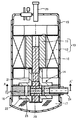
図1は、本実施形態に係るロータリコンプレッサの縦断面図である。図1に示すように、本実施形態のロータリコンプレッサは、円筒状のモータロータ11およびモータステータ12からなる駆動部13および、この駆動部13に連結された圧縮機本体14が、密閉容器であるケーシング15内に収容されて構成されている。
FIG. 1 is a longitudinal sectional view of a rotary compressor according to this embodiment. As shown in FIG. 1, the rotary compressor of this embodiment is a casing in which a
駆動部13のモータステータ12はケーシング15の内周面に固設されている。モータロータ11は回転シャフト16の上端部に固定されており、この状態でモータステータ12の内部に配置されている。
The
回転シャフト16の下端部近傍は、圧縮機本体14に連結されている。また、回転シャフト16の下端部は、ケーシング15内の底部に貯留された潤滑油17に浸漬されている。この潤滑油17は、回転シャフトの下端部に設けられたオイルポンプ(図示せず)によって、例えば、後述する第1、第2の軸受21、22と回転シャフト16との間、ベーン31とベーン溝27との間等の各摺動部分に供給される。
The vicinity of the lower end of the rotating
圧縮機本体14は、シリンダ18、ローリングピストン19、クランク20、第1の軸受21、第2の軸受22からなる。シリンダ18は、回転シャフト16の回転中心を軸とする略円筒形状であり、その外周面がケーシング15の内壁に固着され、内周部にシリンダ室23を形成している。
The
クランク20は、円柱状であり、回転シャフト16の下端部近傍に回転シャフト16の回転中心とは偏心して一体形成されている。また、ローリングピストン19は、円筒形状であり、クランク20に嵌入されている。このようなローリングピストン19は、シリンダ室23内周面の一部に接触してシリンダ室23内に収納されている。
The
第1の軸受21は、シリンダ18の上端面に設けられている。同様に、第2の軸受22は、シリンダ18の下端面に設けられている。そして、これらの第1、第2の軸受21、22によって、シリンダ18の内周面とローリングピストン19との間に、シリンダ室23が形成される。
The
また、シリンダ18には、シリンダ室23に連通する吸入管24が接続されている。
Further, a
図2は、図1の一点鎖線A−A´に沿った断面図である。図2に示すように、シリンダ18には、吸入路25、吐出路26、ベーン溝27およびスリット28がそれぞれ、シリンダ18の内周面に開口し、この開口部分からシリンダ18の半径方向に沿って外周面側に伸びるように設けられている。
FIG. 2 is a cross-sectional view taken along one-dot chain line AA ′ in FIG. As shown in FIG. 2, the
このうち、吸入路25は、図1に示される吸入管24に連通されており、冷媒は、吸入管24、吸入路25を介してシリンダ室23内に吸入される。
Among these, the
吐出路26は、図1に示されるケーシング15の内部空間に開口する開口部(図示せず)と連通しており、シリンダ室23内の冷媒は、吐出路26から、開口部(図示せず)を介してケーシング15内に吐出される。なお、ケーシング15内に吐出された冷媒は、図1に示すように、ケーシング15の上部に設けられた吐出管29から外部に吐出される。
The
ベーン溝27は、吸入路25と吐出路26との間に形成されている。このベーン溝27の端部は、穴部30に連通している。さらに、このベーン溝27および穴部30は、シリンダ18の上端面から下端面にかけて貫通するように形成されている。
The
このベーン溝27には、この溝27の内部からシリンダ室23内に突出すようにベーン31が挿入されている。このベーン31は、一端が穴部30に設けられたスプリング32によって、ベーン溝27に沿う方向に移動可能に支持されている。
A
ベーン31の他端は、ローリングピストン19の外周面に常に当接している。これにより、上述のシリンダ室23は、吸込み室23−1と圧縮室23−2とに分離されている。
The other end of the
スリット28は、ベーン溝27と吸入路25との間に設けられている。このスリット28は、ベーン溝27とスリット28との間のシリンダ18(以下、プレート部33と称す)の疲労破壊を抑制し、かつ、ベーン31の片当たり、焼き付きを抑制することが可能なように設けられている。
The
具体的には、スリット28は、以下に説明するように形成されている。すなわち、図2に示すように、ベーン溝27の溝幅方向の中心とシリンダ18の中心Oとを結ぶ一点鎖線Bと、スリット28のベーン溝側の側面中央bとシリンダ18の中心Oとを結ぶ破線Cと、によって形成される角度をΨとする(以下、このΨをスリット28の角度Ψと称す)。ここで、一点鎖線BをΨ=0とする。このようにスリット28の角度Ψを定義すると、スリット28は、この角度Ψが9°≦Ψ≦14°の範囲になるように形成されている。なお、このスリットの角度Ψの範囲は、以下に説明する解析により求められた範囲である。
Specifically, the
解析においては、プレート部33およびベーン31の表面状態が、混合潤滑状態であると考える。混合潤滑状態とは、ベーン31とプレート部33とが、互いの表面粗さによって、ある部分においては油膜を介して接触しており、他の部分においては直接接触している状態である。
In the analysis, the surface state of the
この状態に基づいて、まず、油膜による圧力pおよび直接接触による圧力pcによってプレート部33にかかる圧力分布を計算する。そして、プレート部33にかかる圧力分布とプレート部33の弾性変形量とを釣り合わせる。これにより、プレート部33に発生する引っ張り応力をスリット角Ψ毎に求めた。
Based on this state, first, it calculates the pressure distribution applied to the
油膜による圧力pは、修正Reynolds方程式である以下の式1により算出した。

また、直接接触による圧力pcは、Greenwood−Tripp理論に基づいて導かれたPatirとChengによる近似式である以下の式3により算出した。
また、上述の油膜による圧力pと直接接触による圧力pcとの総和と、プレート部33の弾性変形量との釣り合わせは、以下のように計算した。
Also, balancing of the sum of the pressure p c by direct contact with the pressure p due to the above-described oil film, an elastic deformation amount of the
まず、プレート部33を、図3に示されるFEMモデルのようにメッシュ状に各要素Mに分割し、上述の式1、式3から、プレート部33のベーン溝27側の表面(以下、プレート部33の表面と称す)上の節点の弾性変形量を有限要素法により求めた。
First, the
各節点の自由度分変位を{u}とすると、離散化された弾性変形式は式4のように示される。
この式4において、[C]は影響係数マトリックス、{f}は各節点に作用する外部荷重である。本解析において{f}は、プレート部33の表面における圧力分布(油膜による圧力pと直接接触による圧力pcとの和)に等価な節点荷重ベクトルである。
In Equation 4, [C] is an influence coefficient matrix, and {f} is an external load acting on each node. In this analysis {f} is an equivalent nodal loads vector (sum of the pressure p c by direct contact with the pressure p due to the oil film) pressure distribution in the surface of the
なお、式4は、式5に示される剛性方程式を変形させた式である。
従って、式4における影響係数マトリックス[C]は、式5における剛性係数マトリックス[K]の逆マトリックスである。なお、この剛性マトリックス[K]は、図3に示されるようなFEMモデル毎に異なるものであり、スリット角Ψを変えることは、剛性マトリックス[K]を変えることに相当する。
Therefore, the influence coefficient matrix [C] in Equation 4 is an inverse matrix of the stiffness coefficient matrix [K] in
以上のようにして、油膜による圧力pと直接接触による圧力pcとの総和と、プレート部33の弾性変形量との釣り合わせを計算した。
As described above, it was calculated and the sum of the pressure p c by direct contact with the pressure p due to the oil film, the balancing of the elastic deformation amount of the
なお、剛性マトリックス[K]は、図3に示されるようなFEMモデルの全要素Mについて要素剛性マトリックス[k]を計算し、共通節点の重ね合わせを行うことにより算出される。要素剛性マトリックス[k]は、以下の式6から算出される。
式6において、[B]は形状マトリックス、[D]は材料物性マトリックス、zはz軸方向、すなわち、図3に示されるFEMモデルの厚さ方向(図3の紙面に対して垂直方向)の座標である。 In Equation 6, [B] is the shape matrix, [D] is the material property matrix, z is the z-axis direction, that is, the thickness direction of the FEM model shown in FIG. 3 (perpendicular to the plane of FIG. 3). Coordinates.
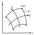
ここで、FEMモデルの各要素Mは、図4に示されるような四角形からなる。本解析においては、図4に示されるxy直交座標系における四角形の各頂点座標(x、y)を、図5に示されるように正規化されたξη座標系の座標(ξ、η)に変換する。この変換は、座標変換の関数Ni´を用いた以下の式7を用いて行われる。
また、要素M内の任意の点のx軸方向、y軸方向の変位をux、uyとし、節点iにおける変位を式8のように定義する。
![]()
![]()
ここで、内挿関数Niにて要素内の任意点の変位を節点変位で表すと式9のようになる。
なお、本解析において、上述の要素をアイソパラメトリック要素と考えると、式9における内挿関数Niは、式7における座標変換の関数Ni´と同一である。 In this analysis, when the above-described element is considered as an isoparametric element, the interpolation function N i in Expression 9 is the same as the function N i ′ of coordinate transformation in Expression 7.
内挿関数Niおよび、この関数の偏導関数は、式10に示される通りである。
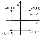
ここで、ξη座標系の要素M´が有する各頂点をmi(ξ、η)=m1(−1、−1)、m2(1、−1)、m3(1、1)、m4(−1、1)とすると、式10は、以下の式11のようになる。
以上に基づいて、式6に示される要素剛性マトリックス[k]は、以下の式12のように変換される。
ここで、[J]はJacobianマトリックスであり、[J]、det[J]は、以下の式13で示される。
また、[B]は形状マトリックス、[D]は材料物性マトリックスはそれぞれ、式14、式15で示される。
なお、式15において、νはポアソン比、Eはヤング率を示す。
In
以上のようにして、図3に示されるようなFEMモデルの全要素Mについて要素剛性マトリックス[k]を計算し、共通節点の重ね合わせを行うことにより剛性マトリックス[K]を算出する。 As described above, the element stiffness matrix [k] is calculated for all the elements M of the FEM model as shown in FIG. 3, and the stiffness matrix [K] is calculated by superimposing common nodes.
解析においては、まずスリット角Ψを規定して剛性マトリックス[K]を計算する。その後、上述したように、式1、式3を用いてプレート部33にかかる圧力分布を計算し、式4を用いてプレート部33にかかる圧力分布とプレート部33の弾性変形量とを釣り合わせる。これにより、プレート部33に発生する応力をスリット角Ψ毎に求めた。その結果を図6に示す。なお、解析条件は以下の通りである。
In the analysis, first, the stiffness angle [K] is calculated by defining the slit angle Ψ. Thereafter, as described above, the pressure distribution applied to the
シリンダ半径:36.5mm
ローリングピストン外径:30.6mm
ベーン溝長:20.0mm
ベーン表面粗さ:0.1μm(Rq)
ベーン溝表面粗さ:0.8μm(Rq)
スリット長:2.5mm
スリット半径:2.5mm
油の粘度:4.2e−3Pa・s
回転数:60Hz
冷媒:CO2
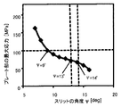
図6は、スリットの角度Ψ[deg]とプレート部33の最大応力[MPa]との関係を示すグラフである。図6より、スリット角Ψを大きくすると、プレート部33の最大応力が小さくなることがわかった。これは、スリット角Ψが大きくなる毎に、プレート部33の厚さが厚くなり、弾性変形し難い構造となるためである。
Cylinder radius: 36.5mm
Rolling piston outer diameter: 30.6mm
Vane groove length: 20.0mm
Vane surface roughness: 0.1 μm (R q )
Vane groove surface roughness: 0.8 μm (R q )
Slit length: 2.5mm
Slit radius: 2.5mm
Oil viscosity: 4.2e-3 Pa · s
Rotation speed: 60Hz
Refrigerant: CO 2
FIG. 6 is a graph showing the relationship between the slit angle ψ [deg] and the maximum stress [MPa] of the
さらに、スリットの角度Ψ[deg]とプレート部33の最大応力[MPa]との関係において、スリット角Ψが9°の点および14°の点に変曲点を有することが発見された。すなわち、スリット角Ψが9°より小さい場合、プレート部33の最大応力が急激に増大し、スリット角Ψが14°より大きい場合、プレート部33の最大応力が急激に減少することが発見された。
Furthermore, it was discovered that the slit angle Ψ has inflection points at a point of 9 ° and a point of 14 ° in the relationship between the angle Ψ [deg] of the slit and the maximum stress [MPa] of the
スリット角Ψが9°より小さい場合、プレート部33の最大応力が急激に増大しているが、これは、スリット角Ψが9°より小さくなると、プレート部33が急激に柔構造となるためである。従って、ベーン31の片当たり、焼きつきの抑制には有効である。しかし、プレート部33の疲労強度限界は一般に200[MPa]であることが知られており、本解析においては、マージンをとって疲労強度限界を100[MPa]と定めると、スリット角Ψが9°より小さい場合、プレート部33の最大応力が100[MPa]を超えてしまい、プレート部33の機械的強度が弱くなるため、疲労破壊されてしまう。
When the slit angle Ψ is smaller than 9 °, the maximum stress of the
一方で、スリット角Ψが14°より大きい場合、プレート部33の最大応力が急激に減少しているが、これは、スリット角Ψが14°より大きくなると、スリット28によるプレート部33の弾性変形効果が得られなくなることを意味する。すなわち、スリット角Ψが14°より大きい場合、ベーン31の片当たり、焼きつきを抑制する効果を期待することはできない。
On the other hand, when the slit angle ψ is larger than 14 °, the maximum stress of the
なお、上述の結果は、解析条件を変えてもほぼ同様の結果が得られた。 The above results were almost the same even when the analysis conditions were changed.
以上より、プレート部33は、この角度Ψが9°≦Ψ≦14°の範囲になるように形成されることにより、プレート部33の疲労破壊が抑制されるとともに、ベーン31の片当たり、焼きつきが抑制されることが分かった。
As described above, the
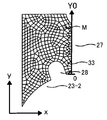
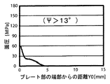
また、上述の解析により、プレート部33において最大応力が発生する箇所は、プレート部33の角度Ψとともに移動することが発見された。図7A乃至図7Cは、それぞれのスリット角Ψにおいて、プレート部33にかかる圧力分布を示しており、横軸に、プレート部33の端部からの距離[mm]、縦軸に面圧[MPa]を示している。ここでプレート部33の端部とは、プレート部33のうち、圧縮室23に接する位置を意味する。すなわち、図3に示すように、プレート部33の端部からの距離Y0[mm]は、プレート部33の端部をY0=0としたときのベーン溝27方向の位置を示す。
Further, it has been found from the above analysis that the portion where the maximum stress is generated in the
まず、プレート部33の角度Ψが13°より大きいとき、図7Aに示すように、プレート部33の端部において面圧が最大になっていることが分かる。
First, when the angle Ψ of the
しかし、プレート部33の角度Ψが13°になると、図7Bに示すように、プレート部33の端部にかかる面圧が図5Aと比較して低下するとともに、プレート部33の端部からおよそ2.5mmの点における面圧が、プレート部33の端部の面圧よりわずかに大きくなることが分かる。
However, when the angle ψ of the
さらに、プレート部33の角度Ψが13°より小さくなると、図7Cに示すように、プレート部33の端部からおよそ2.5mmの点において面圧が最大となっていることが分かる。
Further, when the angle Ψ of the
なお、この現象も、解析条件を変えてもほぼ同様の結果が得られた。 In this phenomenon, almost the same result was obtained even when the analysis conditions were changed.
このように、プレート部33の角度Ψを13°以下にすることにより、プレート部33の端部に大きな面圧がかかることを抑制できる。すなわち、ベーン31の片当たり、焼き付きをより効果的に抑制することができる。このように、プレート部33は、この角度Ψが9°≦Ψ≦13°の範囲になるように形成されることがより好ましい。
In this way, by setting the angle Ψ of the
以上に説明したロータリコンプレッサは、以下のように動作する。まず、モータステータ12によりモータロータ11に磁界を発生させる。すると、この磁界の作用により、モータロータ11に固定された回転シャフト16は回転する。このとき、回転シャフト16の下端部近傍に一体形成されたクランク20は、この回転シャフト16の回転中心軸から偏心して回転する。クランク20が回転すると、これに嵌入されたローリングピストン19は、シリンダ18内を偏心して回転する。
The rotary compressor described above operates as follows. First, a magnetic field is generated in the
ここで、例えばCO2からなる冷媒が吸入路25を介して吸込み室23−1に吸入される。吸込み室23−1は、ローリングピストン19が偏心回転し、吸入路25を通過すると圧縮室23−2に切換わる。圧縮室23−2はローリングピストン19の偏心回転とともに容積が縮小され、これに伴って圧縮室23−2内の冷媒が圧縮される。さらにローリングピストン19の偏心回転により圧縮室23−2内の冷媒の圧力が吐出圧力に到達すると、吐出路26に設けられた図示しない吐出弁が開き、冷媒が、吐出路26、開口部(図示せず)を介してケーシング15内に吐出され、さらにケーシング15上部に設けられた吐出管29から外部に吐出される。
Here, for example, a refrigerant made of CO 2 is sucked into the suction chamber 23-1 through the
以上に説明したロータリコンプレッサによれば、スリット28の角度Ψが9°≦Ψ≦14°の範囲になるようにスリット28が形成されているため、上述のシミュレーション結果から明らかなように、プレート部33の疲労破壊を抑制し、かつ、ベーン31の片当たり、焼きつきを抑制することができる。
According to the rotary compressor described above, the
なお、スリット28の角度Ψは9°≦Ψ≦13°の範囲になるように形成されることが、より好ましい。
It is more preferable that the angle ψ of the
以上に、本実施形態のロータリコンプレッサについて説明した。しかし、本発明は、上述の実施形態に限定されるものではなく、本発明の趣旨を逸脱しない範囲で様々に変形可能である。 The rotary compressor of this embodiment has been described above. However, the present invention is not limited to the above-described embodiment, and various modifications can be made without departing from the spirit of the present invention.
また、上述の実施形態においては、冷媒としてCO2が適用された。CO2は、圧縮室23−2において、例えば12MPa程度まで圧縮されるものである。このように、冷媒を極めて高圧に圧縮する場合には、本発明は特に有効である。しかし、例えば温室効果ガスであるHFC冷媒を冷媒として適用する場合、圧縮室23−2において4MPa程度までしか圧縮されないが、このような冷媒を適用した場合であっても、本発明は有効である。このように、本発明においては、適用される冷媒は限定されない。さらに、シリンダを複数有するロータリコンプレッサにも適用可能である。 In the above-described embodiment, CO 2 is applied as the refrigerant. CO 2 is compressed to, for example, about 12 MPa in the compression chamber 23-2. Thus, the present invention is particularly effective when the refrigerant is compressed to an extremely high pressure. However, for example, when an HFC refrigerant, which is a greenhouse gas, is applied as a refrigerant, the compression chamber 23-2 is compressed only to about 4 MPa, but the present invention is effective even when such a refrigerant is applied. . Thus, in the present invention, the applied refrigerant is not limited. Furthermore, the present invention can be applied to a rotary compressor having a plurality of cylinders.
11・・・モータロータ
12・・・モータステータ
13・・・駆動部
14・・・圧縮機本体
15・・・ケーシング
16・・・回転シャフト
17・・・潤滑油
18・・・シリンダ
19・・・ローリングピストン
20・・・クランク
21・・・第1の軸受
22・・・第2の軸受
23・・・シリンダ室
23−1・・・吸込み室
23−2・・・圧縮室
24・・・吸入管
25・・・吸入路
26・・・吐出路
27・・・ベーン溝
28・・・スリット
29・・・吐出管
30・・・穴部
31・・・ベーン
32・・・スプリング
33・・・プレート部
DESCRIPTION OF
Claims (2)
このケーシングに収納された駆動部と、
この駆動部により回転する回転シャフトと、
この回転シャフトに連結され、前記ケーシングに収納された圧縮機本体と、
を有し、
前記圧縮機本体は、シリンダ室を形成するシリンダと、
このシリンダ室の内周面の一部に接するように前記シリンダ室の内部に配置され、前記回転シャフトの回転により、前記回転シャフトの回転中心軸から偏心して前記シリンダ室内を回転するローリングピストンと、
前記シリンダに設けられた冷媒の吸入部と吐出部との間の内周面において開口し、この開口から前記シリンダの半径方向に向かって、前記シリンダの上端面から下端面にかけて貫通するように設けられたベーン溝と、
一端が前記ローリングピストンに接するように前記ベーン溝に挿入され、前記シリンダ室を吸込み室と圧縮室に2分するベーンと、
前記シリンダの前記吸入部と前記ベーン溝との間の内周面において開口し、この開口から前記シリンダの半径方向に向かって、前記シリンダの上端面から下端面にかけて貫通するように設けられたスリットと、
を具備し、
前記スリットの前記ベーン溝側の側面中央と前記シリンダの中心とを結ぶ直線と、前記ベーン溝の溝幅方向の中心とシリンダの中心とを結ぶ直線とによって規定されるスリットの角度が、9°以上14°以下になるように前記スリットが設けられていることを特徴とするロータリコンプレッサ。 A sealed casing;
A drive unit housed in the casing;
A rotating shaft that is rotated by the drive unit;
A compressor body connected to the rotating shaft and housed in the casing;
Have
The compressor body includes a cylinder forming a cylinder chamber;
A rolling piston that is disposed inside the cylinder chamber so as to be in contact with a part of the inner peripheral surface of the cylinder chamber and rotates in the cylinder chamber eccentrically from the rotation center axis of the rotation shaft by rotation of the rotation shaft;
An opening is formed in the inner peripheral surface between the refrigerant suction portion and the discharge portion provided in the cylinder, and the opening is provided from the opening toward the radial direction of the cylinder so as to penetrate from the upper end surface to the lower end surface of the cylinder. The vane groove formed,
A vane that is inserted into the vane groove so that one end is in contact with the rolling piston and divides the cylinder chamber into a suction chamber and a compression chamber;
A slit provided in the inner peripheral surface between the suction portion of the cylinder and the vane groove, and penetrating from the upper end surface to the lower end surface of the cylinder from the opening toward the radial direction of the cylinder. When,
Comprising
The angle of the slit defined by a straight line connecting the center of the side surface of the slit on the vane groove side and the center of the cylinder and a straight line connecting the center of the groove width direction of the vane groove and the center of the cylinder is 9 °. The rotary compressor is characterized in that the slit is provided so as to be 14 ° or less.
Priority Applications (1)
| Application Number | Priority Date | Filing Date | Title |
|---|---|---|---|
| JP2009219278A JP2011069249A (en) | 2009-09-24 | 2009-09-24 | Rotary compressor |
Applications Claiming Priority (1)
| Application Number | Priority Date | Filing Date | Title |
|---|---|---|---|
| JP2009219278A JP2011069249A (en) | 2009-09-24 | 2009-09-24 | Rotary compressor |
Publications (1)
| Publication Number | Publication Date |
|---|---|
| JP2011069249A true JP2011069249A (en) | 2011-04-07 |
Family
ID=44014754
Family Applications (1)
| Application Number | Title | Priority Date | Filing Date |
|---|---|---|---|
| JP2009219278A Pending JP2011069249A (en) | 2009-09-24 | 2009-09-24 | Rotary compressor |
Country Status (1)
| Country | Link |
|---|---|
| JP (1) | JP2011069249A (en) |
Cited By (2)
| Publication number | Priority date | Publication date | Assignee | Title |
|---|---|---|---|---|
| CN103573622A (en) * | 2013-10-31 | 2014-02-12 | 广东美芝制冷设备有限公司 | Rotating compressor and air cylinder thereof |
| CN115507026A (en) * | 2021-06-23 | 2022-12-23 | Lg电子株式会社 | Rotary compressor |
-
2009
- 2009-09-24 JP JP2009219278A patent/JP2011069249A/en active Pending
Cited By (3)
| Publication number | Priority date | Publication date | Assignee | Title |
|---|---|---|---|---|
| CN103573622A (en) * | 2013-10-31 | 2014-02-12 | 广东美芝制冷设备有限公司 | Rotating compressor and air cylinder thereof |
| CN103573622B (en) * | 2013-10-31 | 2016-06-29 | 广东美芝制冷设备有限公司 | Rotary compressor and cylinder thereof |
| CN115507026A (en) * | 2021-06-23 | 2022-12-23 | Lg电子株式会社 | Rotary compressor |
Similar Documents
| Publication | Publication Date | Title |
|---|---|---|
| CN105003302B (en) | Turbine engine | |
| JP2011220287A5 (en) | ||
| US9145890B2 (en) | Rotary compressor with dual eccentric portion | |
| CN105008722A (en) | Multi-cylinder rotary compressor | |
| JP6225045B2 (en) | Rotor and rotary fluid machinery | |
| JP5548187B2 (en) | Reciprocating compressor | |
| JP2011069249A (en) | Rotary compressor | |
| CN106351833B (en) | Compressor | |
| CN104747450B (en) | Hermetic type compressor | |
| JP6340964B2 (en) | Rotary compressor | |
| WO2021065037A1 (en) | Compressor | |
| JP6090379B2 (en) | Rotary compressor | |
| JP6019669B2 (en) | Rotary compressor | |
| JP2017008918A (en) | Volumetric capacity type machine | |
| JP5068359B2 (en) | Rolling piston compressor | |
| US20200056816A1 (en) | Refrigerant compressor and freezer including same | |
| JPWO2016151769A1 (en) | Rotary hermetic compressor | |
| JP2019039418A (en) | Rotary compressor | |
| JP2015158144A (en) | Rolling piston and rotary fluid machine | |
| JP3744533B2 (en) | Rotary compressor | |
| JP6131795B2 (en) | Rotary compressor | |
| JP5011963B2 (en) | Rotary fluid machine | |
| JP2008280871A (en) | Scotch yoke type oil-free compressor | |
| JP2020033873A (en) | Closed compressor and refrigerator having the same | |
| CN107131126A (en) | Double cylinder type closed compressors |