JP2011054433A - Waterproof connector - Google Patents
Waterproof connector Download PDFInfo
- Publication number
- JP2011054433A JP2011054433A JP2009202662A JP2009202662A JP2011054433A JP 2011054433 A JP2011054433 A JP 2011054433A JP 2009202662 A JP2009202662 A JP 2009202662A JP 2009202662 A JP2009202662 A JP 2009202662A JP 2011054433 A JP2011054433 A JP 2011054433A
- Authority
- JP
- Japan
- Prior art keywords
- electric wire
- wire
- housing
- electric
- waterproof connector
- Prior art date
- Legal status (The legal status is an assumption and is not a legal conclusion. Google has not performed a legal analysis and makes no representation as to the accuracy of the status listed.)
- Pending
Links
Images


Abstract
Description
本発明は、防水コネクタに関する。 The present invention relates to a waterproof connector.
ゴム栓を用いて防水を行う防水コネクタが広く知られている。例えば、下記特許文献のものは、ハウジングの後端部に形成した収容凹部にゴム栓を収容させ、このゴム栓を、収容凹部の内壁と電線の外周の双方に密着させることにより、コネクタを防水している。 Waterproof connectors that perform waterproofing using rubber plugs are widely known. For example, in the following patent document, a connector is waterproofed by housing a rubber plug in a housing recess formed at the rear end of the housing, and bringing the rubber plug into close contact with both the inner wall of the housing recess and the outer periphery of the electric wire. is doing.
ゴム栓の防水性能を高めるには、電線に対してゴム栓を周方向に均一に密着させることが好ましい。その一方、ハウジングから引き出された電線が何らからの拍子で径方向に引っ張られると、ゴム栓は引かれた方向に大きく変形する。そのため、電線に対するゴム栓の密着の仕方が周方向の各部位で不均一となり、シール性能を低下させる恐れがあった。 In order to improve the waterproof performance of the rubber plug, it is preferable that the rubber plug is uniformly adhered to the electric wire in the circumferential direction. On the other hand, when the electric wire drawn out from the housing is pulled in the radial direction with any beat, the rubber plug is greatly deformed in the drawn direction. For this reason, the method of tightly adhering the rubber plug to the electric wire becomes nonuniform in each portion in the circumferential direction, and the sealing performance may be deteriorated.
特に、近年では、銅電線に代わり、軽量化を目的にアルミ二ウム又はアルミニウム合金製の芯線を備えたアルミ線を使用する傾向にある。一般に、アルミ線は銅素線に比して柔軟性に欠け塑性変形し易い。そのため、そうしたアルミ線がひっぱれて変形すると、アルミ線に対するゴム栓の密着の仕方が不均一(場合によっては部分的に隙間が出来る)になり易く、対策が望まれていた。
本発明は上記のような事情に基づいて完成されたものであって、防水コネクタの防水性能を高めることを目的とする。
In particular, in recent years, there is a tendency to use an aluminum wire having a core wire made of aluminum or an aluminum alloy for the purpose of weight reduction in place of a copper electric wire. In general, aluminum wires lack flexibility and are easily plastically deformed compared to copper wires. For this reason, when such an aluminum wire is pulled and deformed, the rubber plug is intimately adhered to the aluminum wire (in some cases, a gap is partially formed), and a countermeasure has been desired.
The present invention has been completed based on the above circumstances, and an object thereof is to improve the waterproof performance of a waterproof connector.
本発明の防水コネクタは、電線を引き出す電線引出部を後端部に形成してなるハウジングと、前記電線の外周に嵌着され前記電線引出部の内壁に弾性的に接触するシール部材と、前記ハウジングのうち前記電線引出部が形成された後端部において前記シール部材の後方に位置して取り付けられて、前記電線引出部から引き出された電線の径方向への移動を規制する移動規制部材と、を備える。 The waterproof connector according to the present invention includes a housing in which a wire lead-out portion for pulling out a wire is formed at the rear end, a seal member that is fitted on the outer periphery of the wire and elastically contacts the inner wall of the wire lead-out portion, A movement restricting member that is attached to a rear end portion of the housing where the wire lead-out portion is formed and positioned behind the seal member and restricts movement of the electric wire drawn out from the wire lead-out portion in the radial direction; .
このようにしておけば、ハウジングから引き出された電線が径方向に引っ張られたとしても、電線の径方向への移動を移動規制部材が規制する。従って、電線のうち移動規制部材から先の部分には、電線を径方向に変位させるような力が作用せず、電線は真っ直ぐな直線形状を維持する。そのため、シール部材は何ら変形を起こさず、電線の外周に密着した状態を保つから、良好な防水性能を発揮することが可能となる。 If it does in this way, even if the electric wire pulled out from the housing is pulled by radial direction, a movement control member will control the movement to the radial direction of an electric wire. Therefore, a force that causes the electric wire to be displaced in the radial direction does not act on the portion of the electric wire that precedes the movement restricting member, and the electric wire maintains a straight linear shape. For this reason, the seal member does not deform at all, and maintains a state of being in close contact with the outer periphery of the electric wire, so that a good waterproof performance can be exhibited.
この発明の実施態様として、以下の構成とすることが好ましい。
・前記移動規制部材は、前記電線を挿通させる挿通孔を形成してなる基部と、前記挿通孔の孔壁に設けられ孔内を通る電線に当接する規制突起とを備える構成とする。
・前記規制突起を、前記挿通孔の孔壁において周方向に等間隔で複数個形成する。
As an embodiment of the present invention, the following configuration is preferable.
The movement restriction member includes a base formed with an insertion hole through which the electric wire is inserted, and a restriction protrusion provided on the hole wall of the insertion hole and abutting against the electric wire passing through the hole.
A plurality of the restriction protrusions are formed at equal intervals in the circumferential direction on the hole wall of the insertion hole.
このような構成としておけば、電線を挿通孔に通す時の抵抗を小さくすることが可能であり、また、電線が径方向のいずれの方向に引っ張られたとしても、それに伴う電線の移動を規制できる。 With such a configuration, it is possible to reduce the resistance when the electric wire is passed through the insertion hole, and even if the electric wire is pulled in any radial direction, the movement of the electric wire accompanying it is regulated. it can.
本発明によれば、防水コネクタの防水性能を高めることが出来る。 According to the present invention, the waterproof performance of the waterproof connector can be enhanced.
<実施形態1>
本発明の実施形態1を図1ないし図5を参照して説明する。
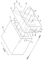
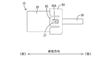
防水コネクタ10は、ハウジング20と、電線30と、ゴム栓(本発明の「シール部材」に相当)40と、電線ホルダ(本発明の「移動規制部材」に相当)50とを主体に構成されている。尚、以下の説明において、図2の左側(相手側コネクタに対する嵌合面側)を前側とし、図2の右側(電線の引き出し側)を後側として説明を行う。
<Embodiment 1>
A first embodiment of the present invention will be described with reference to FIGS.
The
ハウジング20は合成樹脂製であってブッロク型をなす。このハウジング20には前部側にキャビティ23が形成され、後端部に電線引出部25が形成されている。キャビティ23は電線30の先端部に装着された端子金具(図略)を収容する収容室として機能するものである。本実施形態では、キャビティ23をハウジング20の幅方向に2室形成してあり、ハウジング20に電線30が2本装着される構成となっている。
The
電線引出部25は、ハウジング20の後端面21に凹設されている。係る電線引出部25は、各キャビティ23に連通しており、電線引出部25を通じて各電線30がハウジング後方に引き出される構成となっている。
The
電線30は、アルミニウムまたはアルミニウム合金製の素線を複数本を撚り合せた撚り線によって芯線が形成され、この芯線の回りが合成樹脂製の絶縁被覆で覆われた構造となっている。
The
ゴム栓40は、ハウジング20の幅方向に長い横長な板形状をしている。係るゴム栓40には挿通孔42が1対設けられている。挿通孔42はハウジング20に形成された各キャビティ23に対応しており、各電線30がそれぞれ挿通される構成となっている。これら挿通孔42の孔径は電線30の外径より若干狭い設定にしてあり、ゴム栓40が電線30に対して密着するようになっている。
The
ゴム栓40は、電線引出部25に対して後方側から収容される構成となっている。ゴム栓40は電線引出部25に対して一回り大きな形状としてあり、電線引出部25に対してやや圧縮された状態で収容される構成となっている。以上のことから、ゴム栓40を電線引出部25に収容させると、ゴム栓40が電線引出部25の内壁と電線30の双方に隙間なく密着して、ハウジング20の後部をシールする構成となっている。
The
尚、上記したゴム栓40は、厚みが電線引出部25の深さ以下に設定してあり、電線引出部25の内部に収まるようになっている。
The
電線ホルダ50は合成樹脂製であって、ハウジング20の後端面21に相対する基部51と、基部51の外周に形成された側壁部61とを備えてなる。基部51はゴム栓40と同様にハウジング20の幅方向に長い横長な形状をしている。係る基部51には、挿通孔53が1対設けられている。
The
挿通孔53はハウジング20に形成された各キャビティ23に対応しており、各電線30がそれぞれ挿通される構成となっている。そして、図4に示すように、挿通孔53には周方向に等間隔で規制突起55が複数個(この実施形態では90度間隔で、4個)形成されている。これら規制突起55は挿通孔53の孔壁から孔中心に向かって突出しており、孔内を通る電線30の外周面に当接する。このような設定とすることで、孔内を通る電線30の径方向(図4中にて矢印Aで示す方向)への移動を、規制突起55により規制することが出来る。
The
側壁部61はハウジング20の4つの外周壁に対応して4面形成されている。そして、図1に示すように、電線ホルダ50の側壁部61のうち、幅方向の両側に位置する両側壁部61には、それぞれロック片65が形成されている。ロック片65は、その上下両部に形成したスリット66により撓み可能とされたものであり、中央部にはロック孔65Aが形成されている。その一方、ハウジング20のうち、幅方向の両側の外周壁にはロック孔65Aに対応してロック突27がそれぞれ形成されている。
Four
上記電線ホルダ50はハウジング20に対して後方側から被せ付けられ、ハウジング20側のロック突27にホルダ50側のロック片65が係止することで、ハウジング20に対して固定される構成となっている。
The
次に、上記防水コネクタ10の組み付け手順の一例を説明する。防水コネクタ10を組み付けるには、まず、電線ホルダ50とゴム栓40の各挿通孔53、43に電線30をそれぞれ通してやる。その後、電線30の先端に端子金具(図略)をかしめて固定する。そして、電線30の先端に端子金具を固定したら、あとは、電線30を後方からハウジング20に差し込み、電線30の先端に固定した各端子金具をハウジング20のキャビティに収容させる。
Next, an example of the assembly procedure of the
そして、上記した電線30の取り付け作業に続いて、ハウジング20の電線引出部25にゴム栓40を収容させ、その後、電線ホルダ50を、後方からハウジング20の後端部に被せて、電線ホルダ50の側壁部61に形成された各ロック片65を、ハウジング20のロック突27にそれぞれ係止させる。これにて、ハウジング20の後端部に電線ホルダ50が固定され、防水コネクタ10の組み付けが完了する。
Then, following the mounting operation of the
尚、ここで説明した組み付け手順はあくまで一例であり、例えば、ゴム栓40については、ハウジング20の電線引出部25に対して予め収容しておき、ゴム栓40の挿通孔43に、端子金具を取り付けた電線30を押し込みながら、電線30をハウジング20に組み付けるようにしてもよい。
Note that the assembly procedure described here is merely an example. For example, the
次に、上記防水コネクタ10の作用説明を行う。このものは、ハウジング20の後端部に取り付けた電線ホルダ50によって、ハウジング20から引き出された電線30の径方向の移動を規制する構造となっている。そのため、電線30が、図5に示すように径方向(図中では下方向)に引っ張られても、電線ホルダ50から先の部分には電線を径方向に変位させるような力が作用せず、電線30は真っ直ぐな直線形状を維持する。そのため、ゴム栓40は、何ら変形を起こさず、電線30の外周に対して密着した状態を保つから、良好な防水性能を発揮することが可能となる。
Next, the operation of the
また、このものでは、電線ホルダ50の挿通孔53に形成した規制突起55の先端を、電線30に当接させることにより、電線30の径方向に対する移動を規制する構造をとっている。このようにしておけば、電線30に対する接触面積がそれほど大きくならないから、電線30を電線ホルダ50の挿通孔53に通す時の抵抗が小さくなり、電線ホルダ50に対して電線30をスムーズに組み付け出来る。
Moreover, in this thing, the structure which controls the movement with respect to the radial direction of the
尚、規制突起55は周方向に等間隔で形成されているから、電線30が径方向のいずれの方向に引っ張られたとしても、それに伴う電線30の移動規制できる。
In addition, since the
また、このものでは、電線ホルダ50をハウジング20に固定すると、基部51がハウジング20の電線引出部25を閉止する構成となっている。そのため、電線ホルダ50によって電線30の移動規制と共に、ゴム栓40の抜け止めを併せて行うことが出来る。
In this case, when the
<実施形態2>
本発明の実施形態2を図6を参照して説明する。実施形態2は、図6に示すように、電線ホルダを基部51だけの構成とし、基部51をハウジング20の電線引出部25に嵌合させている。このようにしても、抜け止めは必要となるものの、ハウジング20に基部51を固定することが出来るから、実施形態1と同様に基部51に形成した挿通孔53の規制突起55により、電線30の径方向への移動を規制することが可能である。
<
A second embodiment of the present invention will be described with reference to FIG. In the second embodiment, as illustrated in FIG. 6, the electric wire holder includes only the
尚、実施形態2において、電線ホルダを除く他の部品は、実施形態1と同一であるため、これら部品には実施形態1と同一符号を付して説明を省略するものとする。 In the second embodiment, since the other parts except the electric wire holder are the same as those in the first embodiment, these parts are denoted by the same reference numerals as those in the first embodiment and the description thereof is omitted.
<実施形態3>
本発明の実施形態3を図7、図8を参照して説明する。
実施形態1では、電線引出部25から2本の電線30を一括して引き出す構成とし、そこに収容したゴム栓40によって、2本の電線30を一括してシールする防水コネクタ10を例示した(いわゆる一括シールタイプの防水コネクタ)。
<Embodiment 3>
A third embodiment of the present invention will be described with reference to FIGS.
In the first exemplary embodiment, the
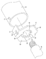
実施形態3では、防水コネクタを構成するハウジングの後部に、筒型の電線引出部70を各電線30に対応してそれぞれ構成している。そして、各電線引出部70の内部にゴム栓75をそれぞれ収容させて、各電線引出部70と各電線30との間を各ゴム栓75によって個別にシールする構造をとっている(いわゆる個別シールタイプの防水コネクタ)。尚、図7中では、防水コネクタを構成するハウジングのうち、電線引出部70のみを示してある。
In the third embodiment, a tubular wire lead-out
そして、このものでは、各電線引出部70に対応して電線ホルダ80を個別に取り付けて、各電線30の移動規制を各電線ホルダ80により個別に行う構成としている。
And in this thing, it is set as the structure which attaches the
電線ホルダ80は実施形態1で例示した電線ホルダ50と基本的な構成は同じであり、電線30を挿通させる挿通孔83を形成した基部81を備える。係る基部81は6角形をしており、その上下両縁部に側壁部91が一対形成されている。
The
各側壁部91にはロック孔91Aがそれぞれ形成されており、これを電線引出部70の外周後端寄りの位置に形成したロック突77に係止させることで、電線引出部70の後端に電線ホルダ50を固定できる構成となっている。
Each
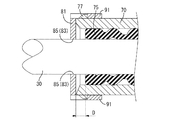
そして、挿通孔83には周方向に等間隔で規制突起85が複数個(この実施形態では4個)形成されている。これら規制突起85は挿通孔83の孔壁から孔中心に向かって突出しており、孔内を通る電線30の外周面に当接する。このような設定とすることで、孔内を通る電線30の径方向への移動を、規制突起85により規制することが出来る。
A plurality (four in this embodiment) of restricting
尚、この実施形態では、規制突起85が電線30を押さえる位置Pからゴム栓75の後端を一定距離Dだけ離している。言い換えれば、そうした設定になるように、電線引出部70の長さをある程度長めに設定してある。このような設定としておけば、距離が離れている分、ゴム栓75は電線30の変形の影響を受け難くなるので、防水性能が一層高まる。
In this embodiment, the rear end of the
<他の実施形態>
本発明は上記記述及び図面によって説明した実施形態に限定されるものではなく、例えば次のような実施形態も本発明の技術的範囲に含まれる。
<Other embodiments>
The present invention is not limited to the embodiments described with reference to the above description and drawings. For example, the following embodiments are also included in the technical scope of the present invention.
(1)上記実施形態1では、基部51の挿通孔53に形成した規制突起55を、孔内を通る電線30に当接させることに、電線の移動規制を行った。この発明は、電線30の径方向に対する移動を規制できればよく、例えば、挿通孔53の大きさを電線30と同じ径、又は電線30より少しだけ狭い径にして、電線30の外周に挿通孔53の孔壁そのものを接触させることで、電線の移動を規制する構成としても、無論よい。
(1) In the first embodiment, the movement of the electric wire is restricted by bringing the
(2)上記実施形態2では、基部(電線ホルダ)51とゴム栓40を別部品とした例を示したが、これら基部51とゴム栓40を2色成形により一体化することも可能である。
(2) In the second embodiment, the base part (electric wire holder) 51 and the
10…防水コネクタ
20…ハウジング
25…電線引出部
30…電線
40…ゴム栓(本発明の「シール部材」に相当)
50…電線ホルダ(本発明の「移動規制部材」に相当)
53…挿通孔
55…規制突起
DESCRIPTION OF
50 ... Electric wire holder (corresponding to "movement restricting member" of the present invention)
53 ...
Claims (3)
前記電線の外周に嵌着され前記電線引出部の内壁に弾性的に接触するシール部材と、
前記ハウジングのうち前記電線引出部が形成された後端部において前記シール部材の後方に位置して取り付けられて、前記電線引出部から引き出された電線の径方向への移動を規制する移動規制部材と、を備えた防水コネクタ。 A housing in which a wire lead-out portion for drawing out the wire is formed at the rear end;
A seal member that is fitted to the outer periphery of the electric wire and elastically contacts the inner wall of the electric wire lead portion;
A movement restricting member that is attached to the rear end of the housing where the wire lead-out portion is formed and is positioned behind the seal member and restricts the movement of the wire drawn from the wire lead-out portion in the radial direction. And waterproof connector with.
前記電線を挿通させる挿通孔を形成してなる基部と、
前記挿通孔の孔壁に設けられ、孔内を通る電線に当接する規制突起とを備えることを特徴とする請求項1に記載の防水コネクタ The movement restricting member is
A base formed with an insertion hole through which the electric wire is inserted;
The waterproof connector according to claim 1, further comprising a restriction protrusion provided on a hole wall of the insertion hole and abutting against an electric wire passing through the hole.
Priority Applications (1)
| Application Number | Priority Date | Filing Date | Title |
|---|---|---|---|
| JP2009202662A JP2011054433A (en) | 2009-09-02 | 2009-09-02 | Waterproof connector |
Applications Claiming Priority (1)
| Application Number | Priority Date | Filing Date | Title |
|---|---|---|---|
| JP2009202662A JP2011054433A (en) | 2009-09-02 | 2009-09-02 | Waterproof connector |
Publications (1)
| Publication Number | Publication Date |
|---|---|
| JP2011054433A true JP2011054433A (en) | 2011-03-17 |
Family
ID=43943221
Family Applications (1)
| Application Number | Title | Priority Date | Filing Date |
|---|---|---|---|
| JP2009202662A Pending JP2011054433A (en) | 2009-09-02 | 2009-09-02 | Waterproof connector |
Country Status (1)
| Country | Link |
|---|---|
| JP (1) | JP2011054433A (en) |
Cited By (6)
| Publication number | Priority date | Publication date | Assignee | Title |
|---|---|---|---|---|
| JP2015041535A (en) * | 2013-08-22 | 2015-03-02 | 矢崎総業株式会社 | Waterproof connector |
| CN104795673A (en) * | 2015-04-28 | 2015-07-22 | 余姚市惠美电器有限公司 | Electric vehicle charging connector assembly |
| JP2018006302A (en) * | 2016-07-08 | 2018-01-11 | 矢崎総業株式会社 | Connector |
| JP2020161239A (en) * | 2019-03-25 | 2020-10-01 | 日本圧着端子製造株式会社 | Retainer and electric connector |
| JP2022045095A (en) * | 2020-09-08 | 2022-03-18 | 矢崎総業株式会社 | Connector housing and wire harness |
| JP2022045094A (en) * | 2020-09-08 | 2022-03-18 | 矢崎総業株式会社 | Connector housing and wire harness |
Citations (3)
| Publication number | Priority date | Publication date | Assignee | Title |
|---|---|---|---|---|
| JP2006252888A (en) * | 2005-03-09 | 2006-09-21 | Sumitomo Wiring Syst Ltd | Connector and protection plug |
| JP2007287464A (en) * | 2006-04-17 | 2007-11-01 | Auto Network Gijutsu Kenkyusho:Kk | Wire holding structure, and wire holder |
| JP2009146768A (en) * | 2007-12-14 | 2009-07-02 | Sumitomo Wiring Syst Ltd | Wire holder |
-
2009
- 2009-09-02 JP JP2009202662A patent/JP2011054433A/en active Pending
Patent Citations (3)
| Publication number | Priority date | Publication date | Assignee | Title |
|---|---|---|---|---|
| JP2006252888A (en) * | 2005-03-09 | 2006-09-21 | Sumitomo Wiring Syst Ltd | Connector and protection plug |
| JP2007287464A (en) * | 2006-04-17 | 2007-11-01 | Auto Network Gijutsu Kenkyusho:Kk | Wire holding structure, and wire holder |
| JP2009146768A (en) * | 2007-12-14 | 2009-07-02 | Sumitomo Wiring Syst Ltd | Wire holder |
Cited By (6)
| Publication number | Priority date | Publication date | Assignee | Title |
|---|---|---|---|---|
| JP2015041535A (en) * | 2013-08-22 | 2015-03-02 | 矢崎総業株式会社 | Waterproof connector |
| CN104795673A (en) * | 2015-04-28 | 2015-07-22 | 余姚市惠美电器有限公司 | Electric vehicle charging connector assembly |
| JP2018006302A (en) * | 2016-07-08 | 2018-01-11 | 矢崎総業株式会社 | Connector |
| JP2020161239A (en) * | 2019-03-25 | 2020-10-01 | 日本圧着端子製造株式会社 | Retainer and electric connector |
| JP2022045095A (en) * | 2020-09-08 | 2022-03-18 | 矢崎総業株式会社 | Connector housing and wire harness |
| JP2022045094A (en) * | 2020-09-08 | 2022-03-18 | 矢崎総業株式会社 | Connector housing and wire harness |
Similar Documents
| Publication | Publication Date | Title |
|---|---|---|
| US9570899B2 (en) | Connector with rubber plug, retainer for retaining rubber plug and a guide formed on a rear part of the retainer for accommodating bending of wires | |
| CN101436736B (en) | Shield connector | |
| JP5394821B2 (en) | Waterproof plug and connector having the waterproof plug | |
| EP2369689B1 (en) | Electrical connector | |
| JP2012199051A (en) | Shield connector | |
| JP2014017119A (en) | Waterproof connector and wire seal | |
| JP2011054433A (en) | Waterproof connector | |
| CN109768419B (en) | Connector with a locking member | |
| JP2010205656A (en) | Waterproof plug, and wire harness having the same | |
| US10333246B2 (en) | Waterproof structure of connector | |
| JP2011154804A (en) | Cable connector | |
| JP5170013B2 (en) | Shield connector | |
| JP2014229376A (en) | Shield connector | |
| JP2011060452A (en) | Shield connector | |
| JP6195137B1 (en) | connector | |
| JP5879956B2 (en) | Connector and wire harness | |
| JP2015204260A (en) | Rubber plug fixing structure | |
| WO2021095475A1 (en) | Waterproof connector | |
| JP2006252888A (en) | Connector and protection plug | |
| JP2007087800A (en) | Shield connector | |
| WO2014192517A1 (en) | Waterproof connector | |
| JP5863181B2 (en) | connector | |
| JP2012038451A (en) | Terminal structure of electric wire | |
| JP2009110685A (en) | Watertight connector | |
| JP2014089806A (en) | Connector and seal member |
Legal Events
| Date | Code | Title | Description |
|---|---|---|---|
| A621 | Written request for application examination |
Free format text: JAPANESE INTERMEDIATE CODE: A621 Effective date: 20111222 |
|
| A131 | Notification of reasons for refusal |
Free format text: JAPANESE INTERMEDIATE CODE: A131 Effective date: 20130226 |
|
| A977 | Report on retrieval |
Free format text: JAPANESE INTERMEDIATE CODE: A971007 Effective date: 20130228 |
|
| A521 | Written amendment |
Free format text: JAPANESE INTERMEDIATE CODE: A523 Effective date: 20130410 |
|
| A02 | Decision of refusal |
Free format text: JAPANESE INTERMEDIATE CODE: A02 Effective date: 20130507 |