JP2011052891A - Air conditioner - Google Patents
Air conditioner Download PDFInfo
- Publication number
- JP2011052891A JP2011052891A JP2009201782A JP2009201782A JP2011052891A JP 2011052891 A JP2011052891 A JP 2011052891A JP 2009201782 A JP2009201782 A JP 2009201782A JP 2009201782 A JP2009201782 A JP 2009201782A JP 2011052891 A JP2011052891 A JP 2011052891A
- Authority
- JP
- Japan
- Prior art keywords
- air
- air conditioner
- stop command
- filter
- cleaning operation
- Prior art date
- Legal status (The legal status is an assumption and is not a legal conclusion. Google has not performed a legal analysis and makes no representation as to the accuracy of the status listed.)
- Granted
Links
- 238000004140 cleaning Methods 0.000 claims abstract description 85
- 239000000428 dust Substances 0.000 claims abstract description 27
- 238000004378 air conditioning Methods 0.000 claims abstract description 19
- 238000010981 drying operation Methods 0.000 claims abstract description 8
- 238000001816 cooling Methods 0.000 description 12
- 230000006870 function Effects 0.000 description 12
- 238000010438 heat treatment Methods 0.000 description 7
- 230000005540 biological transmission Effects 0.000 description 5
- 230000005611 electricity Effects 0.000 description 5
- 230000002354 daily effect Effects 0.000 description 4
- 230000003203 everyday effect Effects 0.000 description 4
- 238000009423 ventilation Methods 0.000 description 4
- CBENFWSGALASAD-UHFFFAOYSA-N Ozone Chemical compound [O-][O+]=O CBENFWSGALASAD-UHFFFAOYSA-N 0.000 description 2
- 230000001877 deodorizing effect Effects 0.000 description 2
- 238000010586 diagram Methods 0.000 description 2
- 238000005192 partition Methods 0.000 description 2
- 230000004044 response Effects 0.000 description 2
- 230000001954 sterilising effect Effects 0.000 description 2
- 238000004659 sterilization and disinfection Methods 0.000 description 2
- XLYOFNOQVPJJNP-UHFFFAOYSA-N water Substances O XLYOFNOQVPJJNP-UHFFFAOYSA-N 0.000 description 2
- 125000002066 L-histidyl group Chemical group [H]N1C([H])=NC(C([H])([H])[C@](C(=O)[*])([H])N([H])[H])=C1[H] 0.000 description 1
- 238000009825 accumulation Methods 0.000 description 1
- 238000007664 blowing Methods 0.000 description 1
- 239000003795 chemical substances by application Substances 0.000 description 1
- 238000001514 detection method Methods 0.000 description 1
- 230000000694 effects Effects 0.000 description 1
- 230000002093 peripheral effect Effects 0.000 description 1
- 238000005057 refrigeration Methods 0.000 description 1
- 238000007789 sealing Methods 0.000 description 1
- 239000000758 substrate Substances 0.000 description 1
- 239000000725 suspension Substances 0.000 description 1
Images


Abstract
Description
本発明は空気調和機に係り、特に運転停止後、毎回自動的にフィルタ掃除機構によりエアフィルタ清掃が実行される空気調和機に関する。 The present invention relates to an air conditioner, and more particularly to an air conditioner in which air filter cleaning is automatically executed by a filter cleaning mechanism every time after operation is stopped.
近年、エアフィルタ掃除を自動的に行うエアフィルタ掃除機構を備えた空気調和機が提供されている。 In recent years, air conditioners equipped with an air filter cleaning mechanism that automatically performs air filter cleaning have been provided.
この種の空気調和機は、室内機に設けたエアフィルタ掃除機構が、空気調和機の運転の停止に対応して、又は運転休止期間中のリモコン操作等に対応して自動的にエアフィルタに付着した埃等を掻き取り、吸引ノズルおよび排気管を通して室外へ排出するか、あるいは掻き取った埃をダストボックス内に収納することにより常にエアフィルタに埃が堆積されないようにしている(例えば、特許文献1参照)。 In this type of air conditioner, the air filter cleaning mechanism provided in the indoor unit automatically turns into an air filter in response to the stop of the operation of the air conditioner or in response to a remote control operation during the operation suspension period. The attached dust is scraped off and discharged to the outside through the suction nozzle and the exhaust pipe, or the scraped dust is stored in the dust box so that the dust is not always accumulated on the air filter (for example, patent document) 1).
しかしながら、特許文献1に記載の空気調和機は、フィルタ清掃運転時において、適切なフィルタ駆動制御を行うことができるが、フィルタ清掃運転の実行に対する考慮がなされていないため、空調運転終了時にフィルタ清掃運転が含まれる機内クリーニング運転を行うように設定されている空気調和機においては、使用者が運転終了のため、リモコンの停止指令ボタンを操作した場合、機内クリーニング運転が開始されるが、この状態を空気調和機が未だ運転を停止していないと間違え、あるいは、意識的に空気調和機の機内クリーニング運転を強制停止させるため、再度リモコンの停止指令ボタンを操作した場合において、機内クリーニング運転とともにフィルタ清掃運転が中止されてしまうため、エアフィルタに埃が付着した状態でもフィルタ清掃が行われず、エアフィルタの表面に埃が堆積して目詰まりを生じてしまい、清潔な状態で省エネ運転を行うことができないという問題がある。 However, although the air conditioner described in Patent Document 1 can perform appropriate filter drive control during the filter cleaning operation, the filter cleaning operation is not taken into consideration, so that the filter cleaning is performed at the end of the air conditioning operation. In an air conditioner that is set to perform an in-flight cleaning operation that includes operation, if the user operates the stop command button on the remote control to end the operation, the in-flight cleaning operation starts. If the air conditioner has not yet stopped operation, or if the air conditioner's in-machine cleaning operation is intentionally stopped, the remote control stop command button is operated again, the filter will be filtered along with the in-machine cleaning operation. The cleaning operation will be canceled, so even if dust is attached to the air filter Filter cleaning is not performed, will be clogged by dust deposited on the surface of the air filter, it is impossible to perform the energy saving operation in a clean condition.
本発明は上述した事情を考慮してなされたもので、使用者が機内クリーニング運転動作を空調運転が継続していると間違え、あるいは意識的に機内クリーニング運転を強制的に停止させるため、再度リモコンの停止指令ボタンを操作した場合でも、フィルタ清掃運転が中止されるのを回避し、エアフィルタに埃が堆積される前に毎回フィルタ清掃することにより、エアフィルタの目詰まりを防止し、常に清潔な状態で省エネ運転が行える空気調和機を提供することを目的とする。 The present invention has been made in consideration of the above-described circumstances. The user mistakes that the in-machine cleaning operation is continued in the air-conditioning operation or consciously forcibly stops the in-machine cleaning operation. Even when the stop command button is operated, the filter cleaning operation is prevented from being stopped, and the filter is cleaned every time before dust is deposited on the air filter, thereby preventing the air filter from being clogged and always clean. An object is to provide an air conditioner that can perform energy saving operation in a safe state.
上述した目的を達成するため、本発明に係る空気調和機は、エアフィルタに付着した埃を自動的に除去するエアフィルタ清掃機構を有する室内機、室外機、および前記室内機に空調運転の停止指令信号を送信する停止指令ボタンを有するリモコンと、空調運転の終了後にフィルタ清掃運転、機内の乾燥運転を含む機内クリーニング運転を実行する制御手段を備えた空気調和機において、前記制御手段は、空調運転中に前記リモコンの停止指令ボタンを操作した場合には、空調運転を終了すると共に前記機内クリーニング運転を実行したのち空気調和機の運転を停止する運転モードと、空調運転中に前記リモコンの停止指令ボタンを操作した後に再度停止指令ボタンを操作した場合には、前記機内クリーニング運転のフィルタ清掃運転のみを実行したのち空気調和機の運転を停止する運転モードを備えたことを特徴とする。 In order to achieve the above-described object, an air conditioner according to the present invention includes an indoor unit having an air filter cleaning mechanism that automatically removes dust adhering to an air filter, an outdoor unit, and a stop of air conditioning operation in the indoor unit. In an air conditioner comprising a remote controller having a stop command button for transmitting a command signal and a control means for executing an in-machine cleaning operation including a filter cleaning operation and an in-machine drying operation after the air-conditioning operation is completed, the control means includes air conditioning When the stop command button of the remote control is operated during operation, the air conditioning operation is terminated and the in-machine cleaning operation is performed, and then the operation of the air conditioner is stopped, and the remote control is stopped during the air conditioning operation. If the stop command button is operated again after operating the command button, only the filter cleaning operation of the in-machine cleaning operation is executed. Characterized by comprising a drive mode to stop the operation of the air conditioner After.
本発明に係る空気調和機によれば、エアフィルタに埃が堆積される前に毎回フィルタ清掃することにより、エアフィルタの目詰まりを防止し、常に清潔な状態で省エネ運転が行える空気調和機を提供することができる。 According to the air conditioner of the present invention, an air conditioner that prevents the air filter from being clogged by cleaning the filter every time before dust is deposited on the air filter, and that can always perform energy saving operation in a clean state. Can be provided.
本発明の一実施形態に係る空気調和機について図面を参照して説明する。 An air conditioner according to an embodiment of the present invention will be described with reference to the drawings.
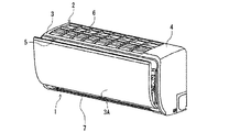
図1および図2に示すように、本実施形態の空気調和機は、室内機1と室外に設置される室外機60(図3)より構成される。 As shown in FIGS. 1 and 2, the air conditioner of the present embodiment includes an indoor unit 1 and an outdoor unit 60 (FIG. 3) installed outdoors.
室内機1は室内機本体2を備え、この室内機本体2は外郭筐体を構成する前面パネル3と、この前面パネル3に覆われ内部に配置される構成部品を取り付ける後本体組立4とから構成され、上下方向に対し幅方向に横長状をなす。
The indoor unit 1 includes an indoor unit
室内機本体2の前面側一部に前面吸込口5が開口され、この前面吸込口5に対向する前面パネル3には開閉駆動機構に支持される可動パネル3Aが嵌め込まれている。
A
室内機本体2の上部には上面吸込口6が設けられる。この上面吸込口6には枠状の桟が嵌め込まれていて、複数の空間部に仕切られている。すなわち、上面吸込口6は常時、全面的に開口された吸込部となっている。これに対して前面吸込口5は、突出した可動パネル3Aと前面パネル3との隙間が、実質的な吸込部となる。
An upper
さらに、室内機本体2の前面下部には吹出口7が開口され、この吹出口7には吹出ルーバー8a、8bが設けられる。
Furthermore, the
各吹出ルーバー8a、8bは、それぞれの回動姿勢によって吹出口7を開閉し、かつ運転条件に応じて熱交換空気の吹出方向を設定できるようになっている。
Each blow-
また、室内機本体2内には、前側熱交換器部9Aと後側熱交換器部9Bとで略逆V字状に形成される熱交換器9が配置される。前側熱交換器部9Aは前面パネル3と間隙を存してほぼ平行な湾曲状に形成され、前面吸込口5と上面吸込口6に対向する。後側熱交換器部9Bは直状に形成され、上面吸込口6と斜めに傾斜して対向する。
Further, in the indoor unit
熱交換器9を構成する前側熱交換器部9Aと後側熱交換器部9Bとの相互間に、室内送風機10が配置される。この室内送風機10は、室内機本体2の一側端のスペースに配置されたファンモータと、このファンモータの回転軸に一方の支軸が連結される横流ファンとから構成される。
An
さらに、前側熱交換器部9Aの下端部は前ドレンパン11a上に載り、後側熱交換器部9Bの下端部は後ドレンパン11b上に載る。前、後ドレンパン11a、11bは、それぞれの熱交換器部9A、9Bから滴下するドレン水を受け、図示しない排水ホースを介して外部に排水できるようになっている。
Furthermore, the lower end portion of the front
前、後ドレンパン11a、11bの一部側壁外面は室内送風機10に近接して設けられ、室内送風機10の横流ファンに対するノーズを構成している。前後ドレンパン11a、11bの側壁部分と吹出口7の各辺部との間は隔壁部材12によって連結され、この空間がノーズと吹出口7とを連通する吹出風路13となっている。
The outer surfaces of the side walls of the front and
一方、前面パネル3と熱交換器9との間に固定枠14が介在されていて、この固定枠14は取付け具を介して後本体組立4に取付けられる。固定枠14は、周囲枠体と補助枠体とから形成されていて、前面吸込口5と上面吸込口6に対向して開口する開口面積が確保されている。
On the other hand, a
固定枠14の前面部には、前面エアフィルタ15と、この内側に二次エアフィルタである空気清浄機ユニット16が取付けられる。すなわち、前面エアフィルタ15および空気清浄機ユニット16は、前面吸込口5と熱交換器9を構成する前側熱交換器部9Aとの間に介設される。
A
さらに、固定枠14の上面部には上面エアフィルタ17が取付けられる。この上面エアフィルタ17は、上面吸込口6と前側熱交換器部9Aの一部および後側熱交換器部9Bとの間に介設されることになる。
Further, an
空気清浄機ユニット16は、流通する空気中の埃に電荷を与える荷電側電極と、電荷を与えられた埃を捕捉する集塵側電極を備えている。各電極表面には、空気に含まれる臭いの成分を吸着する脱臭剤が塗布され、電気集塵機として集塵機能と脱臭機能を併せ有する。
The
一方、前面エアフィルタ15の上端と上面エアフィルタ17の前端との間に沿って、エアフィルタ清掃機構18が取付けられる。このエアフィルタ清掃機構18は、前面エアフィルタ15および上面エアフィルタ17の幅方向長さと同一の幅方向長さに形成され、前後方向にある程度の厚み寸法を有している。
On the other hand, an air
エアフィルタ清掃機構18は前面吸込口5と上面吸込口6との間の部位に配置されていて、前面パネル3における前面部と上面部とが交差する角部内となる。したがって、エアフィルタ清掃機構18は、前面パネル3と熱交換器9との間に必然的に形成されるデッドスペースに配置される。
The air
一方、エアフィルタ清掃機構18は、駆動部に機械的に連結される回転ブラシ19と、この回転ブラシ19を収容するとともに、埃受部を備えたダストボックス21とから構成される。
On the other hand, the air
回転ブラシ19は、駆動部(図示せず)によって回転駆動され、その毛先が進行してくる前面エアフィルタ15もしくは上面エアフィルタ17に接触するよう設けられ、回転ブラシ19が掻き落した埃をダストボックス21内に収納して、このダストボックス21の一端部に接続される排気ユニットにより、室内機から排出されるように構成する。
The rotating
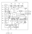
図3に示すように、室内機1の室内機制御装置には電気部品箱に収容されたメイン基板B1、室内機1の前面に取り付けられた表示基板B2、受光基板B3が設けられる。 As shown in FIG. 3, the indoor unit control device of the indoor unit 1 is provided with a main board B <b> 1 housed in an electrical component box, a display board B <b> 2 attached to the front surface of the indoor unit 1, and a light receiving board B <b> 3.
メイン基板B1にはMCU(マイクロコントローラ・ユニット)31をはじめ各種の回路が取り付けられ、MCU31は整流器などを備えた電源回路32を介して電源に接続される。
Various circuits including an MCU (microcontroller unit) 31 are attached to the main board B1, and the
MCU31はCPU、メモリなどを備え、CPUがROM及びRAMとデータのやりとりを行いながらROMに記憶されている制御プログラムを実行する。また、MCU31にはシリアル回路33が接続され、室外機60に搭載された圧縮機、室外送風機の運転を制御する室外機制御回路(図示せず)との信号の伝達を行う。
The
インバータ回路を含む室外機制御回路は整流回路のDC電圧をPWM制御して、DCをACに変換して圧縮機に内蔵された圧縮機モータを可変速駆動する。 The outdoor unit control circuit including the inverter circuit performs PWM control on the DC voltage of the rectifier circuit, converts DC into AC, and drives the compressor motor built in the compressor at a variable speed.
さらに、MCU31には、室内送風機10を駆動制御する駆動回路34が接続され、また、冷凍サイクルにおける室内熱交換器9の中間に介在され除湿弁として作用する二方弁351を駆動制御する駆動回路35が接続され、換気機構361のファンモータを駆動制御する駆動回路36が接続される。
Further, the
さらに、MCU31は、上下風向変更用の上ルーバー371、上下風向変更用の下ルーバー372、左右風向変更用の左右ルーバー373、吸込口前面に配置され前後方向に移動される開閉パネルの移動機構374をそれぞれ駆動制御する各駆動モータの駆動回路37が接続され、さらに、換気機構の通風路切換用のダンパー381、室内機に内蔵されたエアフィルタ清掃機構18において、このエアフィルタ清掃機構18のダストボックス21に溜まった埃を換気装置を利用して室外に排気する際にダストボックス21内のブラシが露出するフィルタ接触開口面を封鎖するよう移動させるシール機構382、上エアフィルタをエアフィルタ清掃機構18に往復移動させる移動機構383、前エアフィルタをエアフィルタ清掃機構18に往復移動させる移動機構384、エアフィルタ清掃機構18に内蔵され移動されるエアフィルタの表面に接触し回転してエアフィルタ表面の埃を掻き取るためのフィルタブラシ駆動装置385をそれぞれ駆動制御する駆動回路38が接続される。
In addition, the
表示基板B2は、室内機1の前面に設けられ、運転状態、運転モードを表示する表示部391が取り付けられ、この表示部391を駆動する駆動回路39を介してMCU31に接続される。
The display board B2 is provided on the front surface of the indoor unit 1, and a
さらに、受光基板B3は、ワイヤレスリモコンと信号のデータの受信発信を行う発信器と受信器を装着した回路部401が取り付けられ、このデータ受送信部401を制御する駆動回路40を介してMCU31に接続される。
Further, the light receiving substrate B3 is provided with a wireless remote controller, a transmitter for receiving and transmitting signal data, and a
またMCU31には、室内温度を検出するために、吸込口5の付近に設けた室内温度センサー41a、湿度センサー41b、吸込空気の汚れ度を検出する空清センサー42、前面パネルの開閉状態検知用のマイクロスイッチ43、エアフィルタの装着状態検知用のマイクロスイッチ44が接続される。
The
また、本空気調和機は、室内の使用者の手元に配置され、図4に示すようなリモコン50を備え、このリモコン50の操作により、室内機1に運転操作信号が送られ、この内容に基づき運転が制御される。
In addition, this air conditioner is arranged at the hand of the user in the room, and includes a
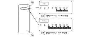
リモコン50は、上部に表示部51が設けられ、この表示部51には現在の月日時間表示部51a、タイマー運転時間帯表示部51b、運転モード表示部51c、設定温度表示部51dが設けられる。
The
中央部には運転モード設定ボタン部52が設けられ、運転モード設定ボタン部52には、冷房運転ボタン、除湿運転ボタン、暖房運転ボタン、停止ボタンB、自動運転ボタン、温度設定ボタン、運転モード表示部51cに表示される空気調和機の省エネ運転状態の表示内容を切り換える表示切換えボタン(「見エルネ」ボタン)、運転モード表示部51cに大きな文字で温度・湿度・電気代などの情報の表示を指示するボタン(「おしえて」ボタン)が設けられ、この「おしえて」ボタンは、1回押すと今回の運転時間、電気代を表示し、2回押すと今回のCO2排出量を表示し、3回押すと今月電気代を表示し、4回押すと現在の室温、湿度、外気温を表示し、5回押すと今日の積算電気代、昨日の積算電気代、一昨日の積算電気代の数値を表示し、6回押すと今日、昨日、一昨日の積算電気代を棒グラフで表示する。また、「見エルネ」ボタンは、押すごとに現在の空気調和機の運転電力(W)、換算電気代(円/h)などを切換えて表示する。
An operation mode
下部には、動作設定ボタン部53が設けられ、この動作設定ボタン部53には、快適気流ボタン、風向ボタン、風量ボタン、スイングボタン、空清(空気清浄)ボタン、入タイマーボタン、切タイマーボタン、戻ボタン、メニューボタン、取消ボタン、決定ボタンが設けられる。
An operation
また、リモコン50は内部にリモコン制御器55を備え、このリモコン制御器55は、時計機能、タイマー機能、表示部制御機能、室内機との制御情報に関する制御機能などのリモコン制御手段として機能するリモコンMCU56を含む制御回路、停止ボタンB(図4)を含む多数の入力ボタンおよび室内機向けリモコン側送受信回路57が搭載されている。これらの各部品は配線接続され、1枚のプリント基板上に搭載されている。
In addition, the
本空気調和機は、リモコン50で少なくとも、冷房運転モード、暖房運転モード、自動運転モードが選択可能となっている。
The air conditioner can select at least a cooling operation mode, a heating operation mode, and an automatic operation mode with the
各モードの運転は、室内機に設置された室内温度センサー41aが検出した室内温度と設定温度との差に基づき空気調和機の運転制御が行われる。
In the operation in each mode, the operation control of the air conditioner is performed based on the difference between the indoor temperature detected by the
冷房運転モードと暖房運転モードは、使用者が冷房或いは暖房を要望し、且つ希望の温度を設定して運転するものであり、リモコン50にて、希望する室内温度を設定し、運転スイッチを操作することで室内を冷房或いは暖房するものであり、この運転は、使用者の寒暑に対する感覚に応じて設定温度を上下調節して好みの温度に調節するもので、使用者の快適性を優先させる運転モードである。
The cooling operation mode and the heating operation mode are those in which the user requests cooling or heating and sets the desired temperature to operate. The
これに対し、自動運転モードは、予め空気調和機自体が、室外の温度や季節などの情報を考慮して、室内の快適性と省エネ性を考慮して、設定温度を自動的に決めるものである。 On the other hand, in the automatic operation mode, the air conditioner itself automatically determines the set temperature in consideration of indoor comfort and energy savings, taking into account information such as outdoor temperature and season. is there.
機内クリーニング運転は、エアフィルタを自動的に清掃するフィルタ清掃運転と、機内乾燥運転からなり、この機内乾燥運転は、冷房運転時には室内熱交換器を除湿或いは暖房運転モードで運転させて乾燥空気を室内機本体内に循環させ、暖房運転時には送風運転により室内機内の乾燥を行う。さらに空気清浄機ユニットを運転することで、オゾンによる室内機内の殺菌運転を行う。 The in-machine cleaning operation consists of a filter cleaning operation for automatically cleaning the air filter and an in-machine drying operation. In this in-machine drying operation, the indoor heat exchanger is operated in a dehumidifying or heating operation mode during cooling operation. It circulates in the main body of the indoor unit, and during the heating operation, the indoor unit is dried by blowing operation. Furthermore, by operating the air purifier unit, the indoor unit is sterilized by ozone.
キレイ設定はエアフィルタ清掃機構を強制的に運転して、エアフィルタの清掃を行う運転モードである。 The clean setting is an operation mode in which the air filter cleaning mechanism is forcibly operated to clean the air filter.
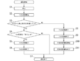
次に本空気調和機の動作について、図6に示すフィルタ清掃のフローチャート図に沿って説明する。冷房運転モードを例にとり説明する。 Next, operation | movement of this air conditioner is demonstrated along the flowchart figure of the filter cleaning shown in FIG. The cooling operation mode will be described as an example.
図3に示すように、リモコン50により、空気調和機を冷房運転させるため、使用者が快適に感じる希望する温度を温度設定ボタンにて設定して、冷房ボタンを操作すると、リモコン50に設定された温度が、設定温度として室内機1に送信される。また、リモコン50の設定温度表示部51dには設定温度が表示される。一方、設定温度はMCU31でメモリに記憶される。室内機1に設置された室内温度センサー41aが、室内機1に吸い込まれる空気の温度を検出し、設定温度との差に基づき空気調和機の冷房運転制御が行われる。
As shown in FIG. 3, in order to cool the air conditioner with the
使用者は、その運転状態により、室内温度が、自分の感覚より低い、或いは高いと感じた場合は、リモコン50の設定温度を高め或いは低めに変更すれば、リモコン50から、室内機1にその情報が送られ、設定温度が変更され、室内機1に配置されている室内温度センサー41aとの差により、冷房運転が行われ、希望の温度に調節される。
If the user feels that the room temperature is lower or higher than his / her sense depending on the operating state, the user can change the set temperature of the
冷房運転継続中に冷房運転を停止する場合、リモコン50の停止ボタンBを操作(1回目)する。停止ボタンBが操作されると、リモコンMCU56、リモコン側送受信回路57を介して室内機に信号が送られ、室内機のMCU31および室外機60の制御回路を介して、室内送風機10および、室外機60に搭載された圧縮機、室外送風機の運転を停止する(S1)。
When stopping the cooling operation while continuing the cooling operation, the stop button B of the
停止ボタンBが操作されて空気調和機の運転が停止されると、リモコンMCU56、リモコン側送受信回路57、室内機のMCU31として、室内機クリーン運転動作が開始され、エアフィルタ清掃機構18が動作し、フィルタ清掃運転が開始される(S2)。
When the stop button B is operated to stop the operation of the air conditioner, the indoor unit clean operation is started as the
室内機のMCU31は、リモコン50から再度停止ボタンBを操作(2回目)されることでの停止指令を受信したか否かを判断する(S3)。
室内機のMCU31が上記停止指令を受信した場合(Yes)、予めリモコンにより設定されているキレイ設定が「あり」か、否かを判断する(S4)。
ここで、キレイ設定は、上記のように再度の停止指令を受信した場合においてもエアフィルタ清掃機構18を強制的に運転して、両エアフィルタ15、16の清掃を行う運転モードである。
The
When the
Here, the clean setting is an operation mode in which the air
キレイ設定が「あり」の場合、フィルタ清掃運転は続行する(S5)。 If the clean setting is “Yes”, the filter cleaning operation continues (S5).
所定時間フィルタ清掃運転が行われた後、フィルタ清掃は終了する(S6)。 After the filter cleaning operation is performed for a predetermined time, the filter cleaning ends (S6).
フィルタ清掃が終了した後、空気調和機の運転は停止する(S7)。 After the filter cleaning is completed, the operation of the air conditioner is stopped (S7).
S3において、室内機のMCU31がリモコン50から再度停止ボタンBを操作(2回目)されることでの停止指令を受信していないと判断した場合(S3のNo)。
機内クリーニング運転が行われ、最初にフィルタ清掃運転が継続する(S8)。
所定時間フィルタ清掃運転行われた後、フィルタ清掃は終了する(S9)。
フィルタ清掃の終了後、機内乾燥運転が開始する(S10)。
機内クリーニング運転の次工程として機内乾燥運転が終了する(S11)。
機内乾燥運転が終了すると、機内クリーニング運転が終了する。
When it is determined in S3 that the
The in-machine cleaning operation is performed, and the filter cleaning operation is first continued (S8).
After the filter cleaning operation is performed for a predetermined time, the filter cleaning ends (S9).
After the filter cleaning is completed, the in-machine drying operation is started (S10).
The in-machine drying operation ends as the next step of the in-machine cleaning operation (S11).
When the in-machine drying operation ends, the in-machine cleaning operation ends.
なお、その後、オゾン発生機能を備えた空気清浄機ユニット16により、殺菌運転を実行させるように構成すれば、さらに、機内の殺菌清浄効果を高めることが出来る。
If the
機内クリーニング運転が終了した後、空気調和機の運転は停止する(S7)。 After the in-machine cleaning operation is completed, the operation of the air conditioner is stopped (S7).
また、上記S4において、室内機のMCU31はキレイ設定が「ない」の場合(S4のNo)には、再度停止ボタンBを操作(2回目)されることでの停止指令を受信したことでフィルタ清掃を含めた機内クリーニング運転を実行せずに空気調和機の運転は停止する(S7)。
Further, in S4, when the
上記リモコン50には、空気調和機を所定の時刻に運転、停止させるためのタイマー機能が備わっている。このリモコン50のタイマー機能は、入タイマー、切タイマーなどの操作ボタンを操作して、毎日の設定時刻に運転を開始、停止することが可能な構成を備え、このタイマー機能を設定することで、指令信号が室内機に送信された場合、開始時刻、停止時刻が制御装置31に記憶され、その後リモコンからの信号発信がなくても、毎日設定時刻に運転を開始、停止を行うように設定されている。
The
これにより、リモコンの電池切れやリモコン発信が室内機に届かない場所にある場合など、室内機がリモコンからの信号を受信できない状態にあっても毎日設定時刻に運転を開始、停止することができる。毎日タイマーは任意にありなしを設定できることにより、必要に応じてタイマーを毎日実施するかを選択できる。さらに、毎日タイマー設定中はリモコンから一定時間ごと(30分毎)にタイマー設定を送信することにより、停電時など室内機のタイマー設定がリセットされた場合でも毎日タイマーに復帰することができ、設定したとおりの動作を続けることができる。毎日タイマーによる運転停止時刻到達時は上記したクリーン運転を行う。またクリーン運転時に埃を排気装置により屋外に強制的に排出するか、機内に配置したダストボックス内に収納しておくかをユーザーが選択することができる。 This makes it possible to start and stop operation at the set time every day even when the indoor unit cannot receive a signal from the remote control, such as when the remote control is out of battery or the remote control transmission is out of reach of the indoor unit. . Since the daily timer can be set arbitrarily, it is possible to select whether the timer is to be executed daily as necessary. In addition, during the daily timer setting, by sending the timer setting from the remote control at regular intervals (every 30 minutes), even if the indoor unit timer setting is reset, such as during a power failure, the timer can be reset to the daily setting. You can continue to work as you did. When the operation stop time is reached by the timer every day, the above-mentioned clean operation is performed. In addition, the user can select whether dust is forcibly discharged to the outside by an exhaust device during clean operation or stored in a dust box arranged in the machine.
また、図7に示すように、リモコン50のタイマー運転時間帯表示部51bには、(a)タイマー設定なしの場合は、運転時間帯は表示されず、(b)タイマー運転が設定された場合は、例えば、6時にタイマーが入り(運転が開始)、9時にタイマーが切れる(運転停止)ことが、高さの異なるバーで表示される。バー表示することで視覚的にタイマー運転時間が見易くなり、また、高さを異ならすことでさらに見易くなる。図8にも同様の表示がなされ、(a)運転中で切タイマー21時の場合、(b)停止中で入タイマー6時の場合を示している。
Further, as shown in FIG. 7, the timer operation
上記のような空気調和機によれば、再度の停止指令を受信した場合においてもエアフィルタ清掃機構を強制的に運転して、エアフィルタの清掃を行う運転モードであるキレイ設定機能を備えることで、使用者が、空調運転停止時に行われる機内クリーニング運転を空気調和機が未だ運転を停止していないと間違え、あるいは、意識的に運転を停止させるため、再度リモコンの停止指令ボタンを操作した場合でも、フィルタ清掃運転が中止されてしまうことを防ぎ、エアフィルタを運転停止ごとにフィルタ清掃することによりフィルタの埃が堆積することによる目詰まりを防止でき、常に清潔な状態で省エネ運転を行うことができる。 According to the air conditioner as described above, even when a stop command is received again, the air filter cleaning mechanism is forcibly operated to provide a clean setting function that is an operation mode for cleaning the air filter. If the user mistakes the in-flight cleaning operation when the air-conditioning operation is stopped if the air conditioner has not stopped the operation yet, or if the user operates the stop command button on the remote control again to stop the operation consciously However, it is possible to prevent the filter cleaning operation from being stopped, and to prevent clogging caused by filter dust accumulation by cleaning the air filter every time the operation is stopped. Can do.
なお、上記空気調和機の動作を冷房運転モードを例にとり説明したが、暖房運転モードあるいは自動運転モードでも同様のステップで実行される。 Although the operation of the air conditioner has been described by taking the cooling operation mode as an example, the same operation is performed in the heating operation mode or the automatic operation mode.
1…室内機、2…室内機本体、3…前面パネル、3A…可動パネル、4…後本体組立、5…前面吸込口、6…上面吸込口、7…吹出口、8a、8b…吹出ルーバー、9…熱交換器、9A…前側熱交換器部、9B…後側熱交換器部、10…室内送風機、11a…前ドレンパン、11b…後ドレンパン、12…隔壁部材、13…吹出風路、14…固定枠、15…前面エアフィルタ、16…空気清浄機ユニット、17…上面エアフィルタ、18…エアフィルタ清掃機構、19…回転ブラシ、21…ダストボックス、31…MCU(マイクロコントローラ・ユニット)、32…電源回路、33…回路シリアル、34…駆動回路、35…駆動回路、351…二方弁、36…駆動回路、361…換気機構、37…駆動モータの駆動回路、371…上下風向変更用ルーバー、372…下側の上下風向変更用ルーバー、373…左右風向変更用ルーバー、374…開閉パネル移動機構、381…通風路切換用のダンパー、382…シール機構、383…移動機構、384…移動機構、385…フィルタブラシ駆動装置、38…駆動回路、39…駆動回路、391…表示部、40…駆動回路、401…データ受送信部、41a…室内温度センサー、41b…湿度センサー、42…空清センサー、43…マイクロスイッチ、44…マイクロスイッチ、50…リモコン、51…表示部、51a…月日時間表示部、51b…タイマー運転時間帯表示部、51c…運転モード表示部、51d…設定温度表示部、52…運転モード設定ボタン部、53…動作設定ボタン部、55…リモコン制御器、56…MCU、57…リモコン側送受信回路、60…室外機。
DESCRIPTION OF SYMBOLS 1 ... Indoor unit, 2 ... Indoor unit main body, 3 ... Front panel, 3A ... Movable panel, 4 ... Rear main body assembly, 5 ... Front suction port, 6 ... Upper surface suction port, 7 ... Outlet, 8a, 8b ... Outlet louver , 9 ... Heat exchanger, 9A ... Front heat exchanger part, 9B ... Rear heat exchanger part, 10 ... Indoor fan, 11a ... Front drain pan, 11b ... Rear drain pan, 12 ... Partition member, 13 ... Blowout air channel, DESCRIPTION OF
Claims (3)
前記制御手段は、空調運転中に前記リモコンの停止指令ボタンを操作した場合には、空調運転を終了すると共に前記機内クリーニング運転を実行したのち空気調和機の運転を停止する運転モードと、
空調運転中に前記リモコンの停止指令ボタンを操作した後に再度停止指令ボタンを操作した場合には、前記機内クリーニング運転のフィルタ清掃運転のみを実行したのち空気調和機の運転を停止する運転モードを
備えたことを特徴とする空気調和機。 An indoor unit having an air filter cleaning mechanism that automatically removes dust adhering to the air filter, an outdoor unit, a remote controller having a stop command button for transmitting a stop command signal for air conditioning operation to the indoor unit, and termination of the air conditioning operation In an air conditioner equipped with a control means for executing an in-machine cleaning operation including a filter cleaning operation and an in-machine drying operation later,
The control means, when operating the stop command button of the remote control during the air conditioning operation, the operation mode to stop the operation of the air conditioner after ending the air conditioning operation and executing the in-machine cleaning operation,
When the stop command button is operated again after operating the stop command button of the remote control during the air conditioning operation, an operation mode for stopping the operation of the air conditioner after performing only the filter cleaning operation of the in-machine cleaning operation is provided. An air conditioner characterized by that.
Priority Applications (1)
| Application Number | Priority Date | Filing Date | Title |
|---|---|---|---|
| JP2009201782A JP5237905B2 (en) | 2009-09-01 | 2009-09-01 | Air conditioner |
Applications Claiming Priority (1)
| Application Number | Priority Date | Filing Date | Title |
|---|---|---|---|
| JP2009201782A JP5237905B2 (en) | 2009-09-01 | 2009-09-01 | Air conditioner |
Publications (2)
| Publication Number | Publication Date |
|---|---|
| JP2011052891A true JP2011052891A (en) | 2011-03-17 |
| JP5237905B2 JP5237905B2 (en) | 2013-07-17 |
Family
ID=43942081
Family Applications (1)
| Application Number | Title | Priority Date | Filing Date |
|---|---|---|---|
| JP2009201782A Active JP5237905B2 (en) | 2009-09-01 | 2009-09-01 | Air conditioner |
Country Status (1)
| Country | Link |
|---|---|
| JP (1) | JP5237905B2 (en) |
Cited By (4)
| Publication number | Priority date | Publication date | Assignee | Title |
|---|---|---|---|---|
| CN104460636A (en) * | 2014-12-25 | 2015-03-25 | 李钢 | Concentrated air conditioner system controller |
| JP2015075302A (en) * | 2013-10-10 | 2015-04-20 | ダイキン工業株式会社 | Air conditioner |
| CN107708835A (en) * | 2015-09-06 | 2018-02-16 | 南京海威机械有限公司 | Powder dust separating device and the intelligence control system comprising the device |
| JP2020020557A (en) * | 2018-08-03 | 2020-02-06 | 三菱重工サーマルシステムズ株式会社 | Air conditioner |
Citations (3)
| Publication number | Priority date | Publication date | Assignee | Title |
|---|---|---|---|---|
| JP2004156901A (en) * | 2004-01-20 | 2004-06-03 | Toshiba Kyaria Kk | Air conditioner |
| JP2005106441A (en) * | 2003-10-02 | 2005-04-21 | Matsushita Electric Ind Co Ltd | Air conditioner |
| JP2008134004A (en) * | 2006-11-28 | 2008-06-12 | Toshiba Kyaria Kk | Indoor unit of air conditioner |
-
2009
- 2009-09-01 JP JP2009201782A patent/JP5237905B2/en active Active
Patent Citations (3)
| Publication number | Priority date | Publication date | Assignee | Title |
|---|---|---|---|---|
| JP2005106441A (en) * | 2003-10-02 | 2005-04-21 | Matsushita Electric Ind Co Ltd | Air conditioner |
| JP2004156901A (en) * | 2004-01-20 | 2004-06-03 | Toshiba Kyaria Kk | Air conditioner |
| JP2008134004A (en) * | 2006-11-28 | 2008-06-12 | Toshiba Kyaria Kk | Indoor unit of air conditioner |
Cited By (4)
| Publication number | Priority date | Publication date | Assignee | Title |
|---|---|---|---|---|
| JP2015075302A (en) * | 2013-10-10 | 2015-04-20 | ダイキン工業株式会社 | Air conditioner |
| CN104460636A (en) * | 2014-12-25 | 2015-03-25 | 李钢 | Concentrated air conditioner system controller |
| CN107708835A (en) * | 2015-09-06 | 2018-02-16 | 南京海威机械有限公司 | Powder dust separating device and the intelligence control system comprising the device |
| JP2020020557A (en) * | 2018-08-03 | 2020-02-06 | 三菱重工サーマルシステムズ株式会社 | Air conditioner |
Also Published As
| Publication number | Publication date |
|---|---|
| JP5237905B2 (en) | 2013-07-17 |
Similar Documents
| Publication | Publication Date | Title |
|---|---|---|
| CN101500618B (en) | Air cleaner | |
| JP4240115B2 (en) | Air conditioner | |
| JPH1114093A (en) | Air conditioner | |
| WO2007026706A1 (en) | Indoor machine of air conditioner | |
| JP2008134004A (en) | Indoor unit of air conditioner | |
| KR101783624B1 (en) | Heat exchange unit for air cleaning | |
| JP5237905B2 (en) | Air conditioner | |
| CN107270400A (en) | Air conditioner room unit and its control method with air-cleaning function | |
| JP4648208B2 (en) | Air conditioner indoor unit | |
| JP4866225B2 (en) | Air conditioner indoor unit | |
| JP2010048493A (en) | Air conditioner | |
| KR100883685B1 (en) | Air conditioner filter cleaning system | |
| CN205137723U (en) | Comfortable new trend purification all -in -one | |
| JP4417709B2 (en) | Air conditioner | |
| JP4878521B2 (en) | Air conditioner indoor unit | |
| JP4589243B2 (en) | Air conditioner indoor unit | |
| WO2007145254A1 (en) | Indoor unit for air conditioner | |
| JP2007170789A (en) | Air conditioner | |
| JP2002089940A (en) | Air conditioner | |
| JP2008045822A (en) | Indoor unit of air conditioner | |
| JP2002061916A (en) | Air conditioner | |
| KR19990038907A (en) | Intake Control Device and Method of Air Conditioner | |
| JP2008045824A (en) | Indoor unit of air conditioner | |
| JP2008057832A (en) | Indoor unit of air conditioner | |
| JP4401189B2 (en) | Air conditioner |
Legal Events
| Date | Code | Title | Description |
|---|---|---|---|
| A621 | Written request for application examination |
Free format text: JAPANESE INTERMEDIATE CODE: A621 Effective date: 20120326 |
|
| TRDD | Decision of grant or rejection written | ||
| A01 | Written decision to grant a patent or to grant a registration (utility model) |
Free format text: JAPANESE INTERMEDIATE CODE: A01 Effective date: 20130312 |
|
| A61 | First payment of annual fees (during grant procedure) |
Free format text: JAPANESE INTERMEDIATE CODE: A61 Effective date: 20130329 |
|
| R150 | Certificate of patent or registration of utility model |
Free format text: JAPANESE INTERMEDIATE CODE: R150 Ref document number: 5237905 Country of ref document: JP Free format text: JAPANESE INTERMEDIATE CODE: R150 |
|
| FPAY | Renewal fee payment (event date is renewal date of database) |
Free format text: PAYMENT UNTIL: 20160405 Year of fee payment: 3 |
|
| R250 | Receipt of annual fees |
Free format text: JAPANESE INTERMEDIATE CODE: R250 |
|
| R250 | Receipt of annual fees |
Free format text: JAPANESE INTERMEDIATE CODE: R250 |
|
| R250 | Receipt of annual fees |
Free format text: JAPANESE INTERMEDIATE CODE: R250 |
|
| R250 | Receipt of annual fees |
Free format text: JAPANESE INTERMEDIATE CODE: R250 |
|
| R250 | Receipt of annual fees |
Free format text: JAPANESE INTERMEDIATE CODE: R250 |
|
| R250 | Receipt of annual fees |
Free format text: JAPANESE INTERMEDIATE CODE: R250 |
|
| R250 | Receipt of annual fees |
Free format text: JAPANESE INTERMEDIATE CODE: R250 |