本願発明に係る携帯機器の1例である携帯電話機の斜視図である。FIG. 1 is a perspective view of a mobile phone which is an example of a mobile device according to the present invention.
図1の状態から第2の筐体を第1の筐体に対して90度時計回りに回転させた状態の平面図である。It is a top view in the state where the 2nd case was rotated 90 degrees clockwise with respect to the 1st case from the state of FIG.
図1の状態から第2の筐体を第1の筐体に対して90度反時計回り回転させた状態の平面図である。FIG. 6 is a plan view of a state in which the second housing is rotated 90 degrees counterclockwise with respect to the first housing from the state of FIG. 1;
図2と図3の状態から第2の筐体を第1の筐体に対してさらに時計回りと反時計回りに90度回転させた状態の平面図である。FIG. 9 is a plan view of a state in which the second housing is further rotated clockwise and counterclockwise 90 degrees with respect to the first housing from the states of FIGS. 2 and 3;
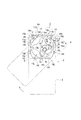
本発明に係る開閉装置の上半分の側の分解斜視図であり、想像線で囲った矢印aの部分は2倍に表示してある。FIG. 2 is an exploded perspective view of the upper half side of the switchgear according to the present invention, in which the part of the arrow a surrounded by an imaginary line is doubled.
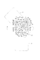
本発明に係る開閉装置の下半分の側の分解斜視図である。It is a disassembled perspective view of the lower half side of the switching device concerning the present invention.
第1の筐体と第2の筐体の閉成状態における開閉装置を示し、(a)はその平面図であり、(b)はその一部拡大平面図である。The switching device in the closed state of a 1st housing | casing and a 2nd housing | casing is shown, (a) is the top view, (b) is the partially expanded top view.
図7の状態から第2の筐体を第1の筐体に対して時計回りに45度回転させた状態における開閉装置の平面図である。FIG. 8 is a plan view of the switchgear in a state in which the second housing is rotated 45 degrees clockwise with respect to the first housing from the state of FIG. 7;
図8の状態から第2の筐体を第1の筐体に対してさらに時計回りに45度回転させた状態における開閉装置の平面図である。FIG. 9 is a plan view of the switchgear in a state where the second housing is further rotated clockwise by 45 degrees with respect to the first housing from the state of FIG. 8;
図9の状態から第2の筐体を第1の筐体に対してさらに時計回りに45度回転させた状態における開閉装置の平面図である。FIG. 10 is a plan view of the switchgear in a state where the second housing is further rotated clockwise by 45 degrees with respect to the first housing from the state of FIG. 9;
図10の状態から第2の筐体を第1の筐体に対してさらに時計回りに45度回転させた状態における開閉装置の平面図である。FIG. 11 is a plan view of the switchgear in a state where the second housing is further rotated clockwise by 45 degrees with respect to the first housing from the state of FIG. 10.
図7の状態から第2の筐体を第1の筐体に対して反時計回りに45度回転させた状態における開閉装置の平面図である。From the state of FIG. 7 against the second housing to the first housing is a plan view of a switchgear in a state rotated 45 degrees counterclockwise.
図12の状態から第2の筐体を第1の筐体に対してさらに反時計回りに45度回転させた状態における開閉装置の平面図である。FIG. 13 is a plan view of the switchgear in a state in which the second housing is further rotated 45 degrees counterclockwise with respect to the first housing from the state of FIG. 12;
図13の状態から第2の筐体を第1の筐体に対してさらに反時計回りに45度回転させた状態における開閉装置の平面図である。FIG. 14 is a plan view of the switchgear in a state where the second housing is further rotated 45 degrees counterclockwise with respect to the first housing from the state of FIG. 13;
図14の状態から第2の筐体を第1の筐体に対してさらに反時計回りに45度回転させた状態における開閉装置の平面図である。FIG. 15 is a plan view of the switchgear in a state in which the second housing is further rotated 45 degrees counterclockwise with respect to the first housing from the state of FIG. 14;
本発明に係る開閉装置を図7の状態で裏側から見た状態の平面図である。FIG. 8 is a plan view of the switchgear according to the present invention as viewed from the back in the state of FIG. 7;
本発明に係る開閉装置を図12の状態で裏側から見た状態の平面図である。It is the top view of the state which looked at the switchgear which concerns on this invention from the back side in the state of FIG.
本発明に係る開閉装置を図13の状態で裏側から見た状態の平面図である。FIG. 14 is a plan view of the switchgear according to the present invention as viewed from the back in the state of FIG. 13;
本発明に係る開閉装置を図14の状態で裏側から見た状態の平面図である。FIG. 15 is a plan view of the switchgear according to the present invention as viewed from the back in the state of FIG. 14;
本発明に係る開閉装置を図15の状態で裏側から見た状態の平面図である。FIG. 16 is a plan view of the switchgear according to the present invention as viewed from the back in the state of FIG. 15;
第2の筐体を第1の筐体に対して時計回りに180度回転させる時の回転規制手段の動作を説明するためのもので、(a)は180度回転直前の状態を示し、(b)は180度回転終了時の状態を示すものである。This is for explaining the operation of the rotation restricting means when rotating the second case 180 degrees clockwise with respect to the first case, where (a) shows a state just before the 180 degree rotation, b) shows the state at the end of the 180-degree rotation.
第2の筐体を第1の筐体に対して反時計回りに180度回転させる時の回転規制手段の動作を説明するためのもので、(a)は180度回転直前の状態を示し、(b)は180度回転終了時の状態を示すものである。This is for explaining the operation of the rotation restricting means when the second case is rotated 180 degrees counterclockwise with respect to the first case, and (a) shows a state immediately before the 180 degree rotation, (B) shows the state at the end of the 180-degree rotation.
本発明に係るスライド防止手段61の構成及びその動作を説明する説明図であり、第1の筐体と第2の筐体の閉成時の状態を示している。It is an explanatory view explaining composition and operation of slide prevention means 61 concerning the present invention, and shows the state at the time of closing of the 1st case and the 2nd case.
本発明に係るスライド防止手段61の構成及びその動作を説明する説明図であり、第2の筐体が第1の筐体に対して時計方向へ90度回転した状態を示している。It is an explanatory view explaining the composition and the operation of slide prevention means 61 concerning the present invention, and the state where the 2nd case rotated 90 degrees in the clockwise direction to the 1st case is shown.
本発明に係るスライド防止手段61の構成及びその動作を説明する説明図であり、第2の筐体が第1の筐体に対して反時計方向へ90度回転した状態を示している。It is an explanatory view explaining the composition and the operation of slide prevention means 61 concerning the present invention, and the state where the 2nd case rotated 90 degrees in the counterclockwise direction to the 1st case is shown.
本発明に係る回動支点調整手段の構成と動作を説明する説明図である。It is an explanatory view explaining composition and operation of rotation pivot adjustment means concerning the present invention.
本発明に係る開閉装置の回転円盤と小径円盤の部分の分解斜視図である。It is an exploded perspective view of a portion of a rotary disc and a small diameter disc of the switchgear according to the present invention.
本発明に係る開閉装置の回転規制手段の可動係止部材の部分の分解斜視図である。It is a disassembled perspective view of the part of the movable locking member of the rotation control means of the switch | opening-closing apparatus which concerns on this invention.
本発明に係る開閉装置のベース部材を示し、(a)は表面側から見た斜視図、(b)は裏側から見た斜視図、(c)は(a)のA−A線断面図である。The base member of the switch | opening-closing apparatus which concerns on this invention is shown, (a) is the perspective view seen from surface side, (b) is the perspective view seen from the back side, (c) is the AA sectional drawing of (a). is there.
本部発明に係る開閉装置の固定係止部材の斜視図である。It is a perspective view of the fixed locking member of the opening and closing device concerning the main part invention.
本部発明に係る開閉装置の固定部材を示し、(a)はその表面側から見た斜視図、(b)はその裏側から見た斜視図である。The fixing member of the switch | opening-closing apparatus which concerns on this invention is shown, (a) is the perspective view seen from the surface side, (b) is the perspective view seen from the back side.
本発明に係る開閉装置のアステロイド動作を説明するための説明図である。It is an explanatory view for explaining asteroid operation of a switching device concerning the present invention.
まず、図7の閉成状態から、第2の筐体4を第1の筐体3に対して水平方向で反時計回りの方向へ押すと、第2の筐体4は、左側の接合凹部6fへ落ち込んでいる固定係止部材14の変形取付ピン部14cを支点としつつ、回転シャフト9をも支点として水平方向の反時計方向へ回転するが、その際に回転シャフト9の回転につれて、図12に示したように、小径円盤8が回転シャフト9を支点として反時計方向へ偏心回転を行ない、同時に小径円盤8の偏心回転により回転円盤7は時計方向へ回転を促すことから、回転シャフト9の回転は定位置回転ではなく、図30に示したようなアステロイド曲線を描いて回転移動することになる。そして、図12に示したように、第2の筐体4の第1の筐体3に対する反時計回りの45度の回転角度で、弾性手段13は最も撓んだ状態にあり、旋回部材10は共に45度旋回した位置にある。そして、固定係止部材14の右側に位置するものは接合凹部6gを脱しているが、左側に位置するものは、その係合ピン部14bがベース部材6の接合凹部6fへ嵌入した状態のままである。この際に、固定係止部材14の左側に位置するものは、その変形取付ピン部14cと係合ピン部14bが、ガイド凸条部6kを挟持したままであるが、右側のものは、その変形取付ピン部14cと係合ピン部14bがガイド凸条部6jより脱出している。
First, when the second housing 4 is pushed in the counterclockwise direction in the horizontal direction with respect to the first housing 3 from the closed state of FIG. It rotates in the counterclockwise direction in the horizontal direction with the rotating shaft 9 also as a fulcrum while using the deformation mounting pin portion 14c of the fixed locking member 14 which has fallen to 6f as a fulcrum. As shown in FIG. 12, the small diameter disc 8 performs eccentric rotation in the counterclockwise direction with the rotation shaft 9 as a fulcrum, and at the same time, the rotation of the small diameter disc 8 promotes rotation in the clockwise direction. Is not a fixed position rotation, but is rotationally moved by drawing an asteroid curve as shown in FIG. Then, as shown in FIG. 12 , the elastic means 13 is in the most bent state at the counterclockwise 45 ° rotation angle of the second case 4 with respect to the first case 3, and the turning member 10 is Are both at a 45 degree turn. And although the thing located in the right side of the fixed locking member 14 takes out the joining recessed part 6g, the thing located in the left side is the state where the engagement pin part 14b was inserted in the joining recessed part 6f of the base member 6. It is. At this time, the one located on the left side of the fixed locking member 14 remains holding the guide ridges 6k while the deformation mounting pin portion 14c and the engagement pin portion 14b hold the guide protruding strip portion 6k. The deformed mounting pin portion 14c and the engagement pin portion 14b are separated from the guide ridges 6j.