JP2011031981A - Liquid pouring container and inner plug used for the same - Google Patents
Liquid pouring container and inner plug used for the same Download PDFInfo
- Publication number
- JP2011031981A JP2011031981A JP2009183258A JP2009183258A JP2011031981A JP 2011031981 A JP2011031981 A JP 2011031981A JP 2009183258 A JP2009183258 A JP 2009183258A JP 2009183258 A JP2009183258 A JP 2009183258A JP 2011031981 A JP2011031981 A JP 2011031981A
- Authority
- JP
- Japan
- Prior art keywords
- container
- liquid
- wall portion
- flow path
- support wall
- Prior art date
- Legal status (The legal status is an assumption and is not a legal conclusion. Google has not performed a legal analysis and makes no representation as to the accuracy of the status listed.)
- Granted
Links
Images


Abstract
Description
本発明は、液体注出容器及びこれに用いる中栓に関する。 The present invention relates to a liquid dispensing container and an inner stopper used therefor.
近年、洗浄液等の液体を収容した容器として、トリガーポンプを備えた容器、即ちレバーの操作によりポンプを作動させて、一定量の洗浄液等を取り出す液体注出容器が提案されている。この種の液体注出容器は、通常、内部の洗浄液等が少量となった場合に、内容液の補充ができるように構成されており、内容液の補充容器としては、経済性や使用後の廃棄の観点から軟質の樹脂製シートからなる包装体が多用されている。 In recent years, as a container for storing a liquid such as a cleaning liquid, a container having a trigger pump, that is, a liquid dispensing container for taking out a certain amount of cleaning liquid or the like by operating the pump by operating a lever has been proposed. This type of liquid dispensing container is usually configured so that the content liquid can be replenished when the amount of internal cleaning liquid becomes small. From the viewpoint of disposal, a package made of a soft resin sheet is often used.
上記の液体注出容器に内容液を補充する際には、トリガーポンプを容器本体から取り外す。一般に、トリガーポンプにはディップチューブが接続されているため、このディップチューブに付着している内容液により周囲を汚しやすい。
また、液体注出容器に内容液を補充する際には、当該液体注出容器の口部が小径であること、及び補充容器の液体注出口を開口状態に保持するのが難しい等の観点から、補充作業に熟練を要する。
When replenishing the liquid dispensing container with the content liquid, the trigger pump is removed from the container body. In general, since a dip tube is connected to the trigger pump, the surroundings are easily contaminated by the content liquid adhering to the dip tube.
In addition, when refilling the liquid dispensing container with the content liquid, from the viewpoints that the mouth of the liquid dispensing container has a small diameter and it is difficult to keep the liquid dispensing outlet of the refilling container open. , Skill is required for replenishment work.
そこで、従来、上記の液体注出容器への内容液の補充を容易なものとするため、ディップチューブを容器本体内に残した状態で、トリガーポンプを取り外すことができる液体注出容器が提案されている。
例えば、特許文献1には、注入窓を穿設した筒部材が係止片により口頸部に固定され、該筒部材の下方に液吸い上げ用のパイプが延設された液体噴射器が開示されている。
特許文献2には、液体注入用窓孔を穿設すると共に、内面に突条を周設した吊下げ筒が口頸部に固定され、該吊下げ筒の下方に吸上パイプが垂下された縦形ポンプ付き容器が開示されている。
特許文献3には、容器体口頚に連結部材が嵌着固定され、該連結部材に下部パイプが嵌着固定されたトリガー式液体噴出容器が開示されている。
特許文献4には、容器本体の口部に保持具が取り付けられ、該保持具に吸引パイプが取り付けられた容器用ポンプ体が開示されている。
特許文献5には、容器開口部に、内容液吸い上げパイプを保持するパイプホルダが装着されたポンプ付替容器が開示されている。
Therefore, conventionally, in order to facilitate the replenishment of the content liquid into the liquid dispensing container, a liquid dispensing container in which the trigger pump can be removed with the dip tube remaining in the container body has been proposed. ing.
For example,
In
Patent Document 5 discloses a pump replacement container in which a pipe holder for holding a content liquid suction pipe is attached to a container opening.
また、従来、補充操作を容易にする観点から、補充用容器の液体注出口に、液体注出容器のノズルを挿入して内容液の補充ができる容器が提案されている。
例えば、特許文献6には、パウチ容器に接合されたスパウト部材と、ボトル容器に固定された本体キャップとからなる容器連結具集合体が開示されている。
特許文献7には、パウチ本体にノズル受け部を設け、該ノズル受け部に弱シール部が設けられたパウチと、該ノズル受け部に差し込まれ弱シール部を開封する注出ノズルが設けられた容器とが開示されている。
Conventionally, from the viewpoint of facilitating the replenishment operation, there has been proposed a container that can be replenished with the content liquid by inserting the nozzle of the liquid dispensing container into the liquid dispensing outlet of the replenishing container.
For example,
In Patent Document 7, a nozzle receiving portion is provided in the pouch body, a pouch having a weak seal portion provided in the nozzle receiving portion, and a dispensing nozzle inserted into the nozzle receiving portion to open the weak seal portion are provided. A container is disclosed.
しかしながら、特許文献1〜5の技術では、取り外した注出体により周囲を汚すことは防げるものの、内容液補充容器の開口部の開口状態を維持することが困難であるため、補充作業の煩雑さを十分に解消できていない。
また、特許文献6〜7の技術では、容器本体側に設けられたスパイク針部や注出ノズル(以下、総じて注出ノズルという)を通じて、内容液を容器本体に補充することとなる。このため、比較的、大径の注出ノズルが設けられた液体注出容器には適用できるものの、小径の注出ノズルが設けられた液体注出容器では、内容液の補充に長時間を要し、補充作業が煩雑となる。特に、ディップチューブが設けられた液体注出容器では、ディップチューブを通じて容器本体に内容液を補充することは困難である。
そこで、本発明は、容器の形態等に制限されず、液体注出容器への内容液の補充を容易とする中栓及びこれを用いた液体注出容器を目的とする。
However, in the techniques of
Further, in the techniques of
Therefore, the present invention is not limited to the form of the container and the like, and an object thereof is an inner plug that facilitates replenishment of the liquid content into the liquid dispensing container and a liquid dispensing container using the same.
本発明の中栓は、内容液を収容する容器本体を有する容器の中栓であって、前記容器本体の口部に嵌合可能な筒状の主壁部と、該主壁部の下部に連設された底壁部と、前記主壁部の内方に位置し、前記底壁部から上方に突出するように設けられた支持壁部とを備え、前記主壁部の内方かつ前記底壁部の上方に、上下方向の第一の流路が設定されると共に、該第一の流路を囲んで第二の流路が設定され、前記支持壁部は、前記第一の流路を囲んで又は該第一の流路を中に挟んで対向する位置に設けられ、前記第一の流路と前記第二の流路とが、水平方向に向いて連通されると共に、前記底壁部に、前記容器本体と前記第一の流路とを連通する第一の連通孔及び前記容器本体と前記第二の流路とを連通する第二の連通孔が形成されていることを特徴とする。
前記支持壁部は、筒状であり、前記支持壁部には、前記第一の流路と前記第二の流路とを連通する開口部が形成されていてもよく、前記支持壁部は、その上端面が傾斜面とされていることが好ましい。
前記支持壁部は、前記底壁部から上方に突出する2以上の突出壁からなり、前記第一の流路と前記第二の流路とは、前記突出壁間の間隙により連通されていてもよい。
前記支持壁部の上端には、内容液を補充する際に対象となる内容液補充容器を破断するための刃部が形成されていることが好ましい。
The inner stopper of the present invention is an inner stopper of a container having a container main body for containing the content liquid, and has a cylindrical main wall portion that can be fitted into the mouth portion of the container main body, and a lower portion of the main wall portion. A bottom wall portion provided continuously, and a support wall portion located inward of the main wall portion and provided so as to protrude upward from the bottom wall portion; and inward of the main wall portion and the A first flow path in the vertical direction is set above the bottom wall, and a second flow path is set around the first flow path, and the support wall is formed with the first flow path. It is provided at a position surrounding the path or facing the first flow path, and the first flow path and the second flow path communicate in a horizontal direction, and A first communication hole that communicates the container body and the first flow path and a second communication hole that communicates the container body and the second flow path are formed in the bottom wall portion. Special To.
The support wall may be cylindrical, and the support wall may be formed with an opening that communicates the first flow path and the second flow path. The upper end surface is preferably an inclined surface.
The support wall portion includes two or more projecting walls projecting upward from the bottom wall portion, and the first flow path and the second flow path are communicated by a gap between the projecting walls. Also good.
It is preferable that an upper end of the support wall is formed with a blade portion for breaking a content liquid replenishing container which is a target when the content liquid is replenished.
本発明の液体注出容器は、本発明の前記中栓と、内容液を収容する容器本体と、前記内容液を前記容器本体外へ注出する注出体とを有し、該注出体には、前記容器本体と嵌合するための装着キャップ、及び前記内容液を前記注出体に導く導入部が設けられ、該導入部は、前記第一の連通孔と液密に接続されていることを特徴とする。
前記注出体は、レバーの操作により内容液を吐出するトリガーポンプであり、前記第一の連通孔には、前記容器本体の内底部に向かって垂下するディップチューブが液密に接続されていることが好ましい。前記導入部と、前記第一の連通孔とを接続する接続部材が設けられ、該接続部材には、前記導入部と嵌合する導入口、前記第一の連通孔と嵌合する接続管、及び、前記導入口と前記接続管とを連通する流路が形成されていてもよい。前記中栓には、前記注出体と嵌合する第一の嵌合部と、前記容器本体と嵌合する第二の嵌合部とが設けられ、前記中栓と前記容器本体との嵌合強度は、前記中栓と前記注出体との嵌合強度より高いことが好ましい。
The liquid dispensing container of the present invention includes the inner plug of the present invention, a container main body that contains the content liquid, and a pouring body that pours the content liquid out of the container main body. Is provided with a mounting cap for fitting with the container body and an introduction part for guiding the content liquid to the extraction body, and the introduction part is liquid-tightly connected to the first communication hole. It is characterized by being.
The pouring body is a trigger pump that discharges the content liquid by operating a lever, and a dip tube that hangs down toward the inner bottom of the container body is liquid-tightly connected to the first communication hole. It is preferable. A connection member that connects the introduction portion and the first communication hole is provided, and the connection member includes an introduction port that fits the introduction portion, a connection pipe that fits the first communication hole, And the flow path which connects the said inlet and the said connecting pipe may be formed. The inner plug is provided with a first fitting portion for fitting with the extraction body and a second fitting portion for fitting with the container main body, and the fitting between the inner plug and the container main body is provided. The combined strength is preferably higher than the fitting strength between the inner plug and the extraction body.
本発明の中栓によれば、第一の流路を囲んで又は第一の流路を中に挟んで対向する位置に支持壁部が、設けられ、第一の流路と第二の流路とは水平方向に連通されているため、容器の形態等に制限されず、液体注出容器への補充作業を容易にできる。
前記支持壁部を筒状とすることで、内容液を補充する際に、内容液補充容器の開口部への挿入が容易である。
支持壁部の上端面を傾斜面とすることで、内容液補充容器の破断が容易である。
支持壁部を底壁部から上方に突出する2以上の突出壁とすることで、内容液をより円滑に補充できる。
支持壁部の上端に刃部を形成することで、内容液補充容器の破断が容易である。
According to the inner plug of the present invention, the support wall is provided at a position that surrounds the first flow path or faces the first flow path therebetween, and the first flow path and the second flow path are provided. Since it is communicated with the path in the horizontal direction, it is not limited to the form of the container and the like, and the refilling operation to the liquid dispensing container can be facilitated.
By making the support wall part cylindrical, when the content liquid is replenished, it can be easily inserted into the opening of the content liquid replenishment container.
By making the upper end surface of the support wall portion an inclined surface, the content liquid replenishing container can be easily broken.
By making the support wall part into two or more projecting walls projecting upward from the bottom wall part, the content liquid can be replenished more smoothly.
By forming the blade portion at the upper end of the support wall portion, the content liquid replenishing container can be easily broken.
また、本発明の液体注出容器によれば、本発明の中栓を備えているため、内容液の補充作業が容易である。
加えて、ディップチューブが中栓に接続されているため、注出体を容器本体から取り外した際に、内容液で周囲を汚すことがない。
中栓に、第一の嵌合部と第二の嵌合部とを設け、中栓と容器本体との嵌合強度を中栓と注出体との嵌合強度より高くすることで、中栓が装着された注出体を容器本体に嵌合した際に、中栓は容器本体に移行し固定される。このため、容器本体への中栓の取り付け作業が容易となり、液体注出容器の生産性の向上が図れる。
Further, according to the liquid dispensing container of the present invention, since the inner plug of the present invention is provided, the replenishment work of the content liquid is easy.
In addition, since the dip tube is connected to the inner plug, the surroundings are not soiled with the content liquid when the dispenser is removed from the container body.
The inner plug is provided with a first fitting portion and a second fitting portion, and the fitting strength between the inner plug and the container body is higher than the fitting strength between the inner plug and the dispenser. When the pouring body fitted with the stopper is fitted to the container body, the inner stopper is moved to the container body and fixed. For this reason, it becomes easy to attach the inner stopper to the container body, and the productivity of the liquid dispensing container can be improved.
(第一の実施形態)
以下、本発明の第一の実施形態に係る液体注出容器を図1〜2を参照して説明する。
図1に示すように、液体注出容器1は、内容液が収容された容器本体3と、内容液を容器本体3の外へ注出する注出体2と、注出体2を口部30に装着する装着キャップ20と、口部30に嵌合された中栓4と、中栓4に接続され容器本体3の内底部に垂下するディップチューブ6とを備えている。
(First embodiment)
Hereinafter, a liquid dispensing container according to a first embodiment of the present invention will be described with reference to FIGS.
As shown in FIG. 1, the
容器本体3は、上部が口部30となっており、口部30の外周面には雄ネジが形成されている。
The upper part of the
本実施形態における注出体2は、トリガーポンプである。注出体2には、内容液を吐出する吐出口14が設けられ、吐出口14の下方には、レバー16が設けられている。注出体2の内部には、シリンダ11が設けられ、シリンダ11内には、レバー16と連動し、上下に摺動するピストン10が設けられている。シリンダ11には、内容液をシリンダ11に導入する導入部12が接続され、導入部12は、後述する中栓4の第一の連通孔52と、液密かつ着脱自在に嵌合されている。
この注出体2は、レバー16の操作により、ピストン10を摺動させて導入部12で内容液を吸い上げ、吸い上げた内容液を吐出口14から吐出する機構とされている。
The
The
装着キャップ20は、中央部が円形に開口された天壁部22と、天壁部22の外周縁から下方に向けて延設されると共に、内周面に雌ネジが形成された下筒部24とを備えている。この装着キャップ20は、外周面に雄ネジが形成された口部30を有する容器本体3に装着される。
The mounting
中栓4は、例えば、ポリエチレン、ポリエチレンテレフタレート、ポリプロピレン、塩化ビニル、シリコンエラストマー、ウレタン等、通常、液体注出容器等に用いられる材質を成形してなるものである。
図2(a)〜(f)に示すように、中栓4は、口部30と嵌合する略円筒形の主壁部40と、主壁部40の下部に連設された底壁部50とを備えるものである。主壁部40の上端周縁には、フランジ42が設けられている。底壁部50の略中央には、容器本体3内の内容液が流通する第一の連通孔52が形成され、該第一の連通孔52の外側には、第二の連通孔56が形成されている。
底壁部50は、図2(b)に示すように、第一の連通孔52を形成する環状底壁部53と、環状底壁部53から主壁部40へ向かって放射状に延びる帯状底壁部51により構成されている。
The
As shown in FIGS. 2 (a) to 2 (f), the
2B, the
帯状底壁部51上には、主壁部40の内方に、底壁部50から上方に突出する支持壁部60が、第一の連通孔52を囲むように設けられている。支持壁部60は、その軸線が主壁部40の軸線と同一である略円筒形とされ、支持壁部60の上端面は、略水平とされている。図2(d)に示すように、支持壁部60の底壁部50上の高さH2は、主壁部40の高さH1より低くされている。即ち、支持壁部60は、中栓4を容器本体3の口部30に嵌合した状態にて、支持壁部60の上端が口部30から突出しない形状とされている。
支持壁部60の下方には、支持壁部60の内外を連通する矩形の開口部62が帯状底壁部51間に形成されている。
中栓4の主壁部40内において、支持壁部60で囲まれた領域は、上下方向の第一の流路とされ、支持壁部60と主壁部40とで囲まれた領域は、上下方向の第二の流路とされている。そして、第一の流路と第二の流路とは、開口部62により水平方向に連通されている。
On the belt-like
Below the
In the
底壁部50には、環状底壁部53から下方に延びる内容液流通管54が設けられている。図1に示すように、この内容液流通管54にディップチューブ6の一端を挿入することで、第一の連通孔52とディップチューブ6とが液密に接続される。
The
次に、液体注出容器1への内容液の補充方法を説明する。
まず、装着キャップ20を螺脱し、注出体2を容器本体3から取り外す。この段階で、ディップチューブ6は、中栓4と共に容器本体3内に残存した状態である。
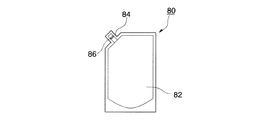
次いで、補充用内容液が収容された内容液補充容器の一部を開口する。この内容液補充容器としては、例えば、図3に示す内容液補充容器80が挙げられる。
内容液補充容器80は、可撓性フィルムを成形して得られる袋本体82に、その一部から突出する矩形の注出部材84が設けられたものである。注出部材84の途中には、剥離可能な仕切りシール部86が設けられている。
Next, a method for replenishing the liquid into the
First, the mounting
Next, a part of the content liquid replenishing container containing the replenishing content liquid is opened. An example of the content liquid replenishment container is a content
The content
注出部材84は、図4(a)に示すように、注出部材84を開口した際の外径D1が、主壁部40の内径d1より小さく、かつ、注出部材84を開口した際の内径D2が、支持壁部60の外径d2よりも大きいものとされている。注出部材84は、このような大きさであることで、支持壁部60と嵌合され、補充用内容液を溢さずに口部30から充填することができる。
As shown in FIG. 4A, when the pouring
補充用内容液の補充にあたっては、図4(a)に示すように、内容液補充容器80の注出部材84の一部を切断して開口し、注出口88とする。次いで、注出口88を開き、注出部材84に支持壁部60を挿入する。支持壁部60は、注出部材84に挿入されると、注出部材84を広げるように作用し、仕切りシール部86を剥離させ、注出部材84に補充用内容液の流路を形成する。そして、図4(b)に示すように、注出部材84と支持壁部60とが嵌合された状態となる。
注出部材84に流路が形成されると、袋本体82内の補充用内容液は、前記流路を流通し、主に支持壁部60内に流入する。そして、図2(f)に示すように、補充用内容液は、矢印Aの流れで支持壁部60内に流入し、次いで開口部62を通過して支持壁部60外へ流出する。支持壁部60外に流出した補充用内容液は、第二の連通孔56を流下し、容器本体3内に補充される。また、容器本体3内の空気は、矢印Bのように、第二の連通孔56から容器本体3外へ排出される。
When the replenishment content liquid is replenished, as shown in FIG. 4A, a part of the dispensing
When the flow path is formed in the dispensing
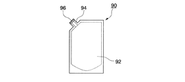
また、例えば、内容液補充容器としては、図5に示すような内容液補充容器90が挙げられる。
内容液補充容器90は、可撓性フィルムを成形して得られる袋本体92に、その一部から突出した略円筒形の注出部材94が設けられたものである。注出部材94は、その端面が薄膜96により封止されている。注出部材94は、注出部材84と同様に、その外径が主壁部40の内径よりも小さく、内径が支持壁部60の外径より大きいものとされている。
内容液の補充にあたっては、内容液補充容器90の薄膜96を支持壁部60に押し付ける。そして、薄膜96を破断させ、注出部材94に支持壁60を挿入する。こうして、補充用内容液は、注出部材94を流通し、支持壁部60内に流入する。支持壁部60に流入した補充用内容液は、開口部62、第二の連通孔56とを順に流通し、容器本体3に充填される。
Further, for example, the content
The content
In replenishing the content liquid, the
このように、本実施形態の液体注出容器は、支持壁部と注出部材とを嵌合した状態で、内容液を補充できる。このため、補充用内容液を溢すことなく、液体注出容器に補充することができると共に、注出部材の注出口を開口状態に維持しながら内容液を補充できる。
さらに、この液体注出容器によれば、支持壁部に開口部が形成されているため、支持壁部内に流入した補充用内容液を支持壁部外へ速やかに流出させ、流出した補充用内容液を第二の連通孔から容器本体内へ充填できる。即ち、図2(f)の矢印Aのように内容液が流通することで、第一の連通孔から内容液を補充するのに比べ、補充作業を格段に円滑なものとすることができる。
Thus, the liquid pouring container of this embodiment can replenish the content liquid in a state in which the support wall portion and the pouring member are fitted. For this reason, it is possible to replenish the liquid dispensing container without overflowing the replenishing content liquid, and it is possible to replenish the content liquid while maintaining the dispensing outlet of the dispensing member in an open state.
Further, according to this liquid dispensing container, since the opening is formed in the support wall, the replenishment content liquid that has flowed into the support wall is quickly drained out of the support wall, and the replenishment content that has flowed out. The liquid can be filled into the container body from the second communication hole. That is, when the content liquid flows as indicated by an arrow A in FIG. 2 (f), the replenishment operation can be made much smoother than when the content liquid is replenished from the first communication hole.
本実施形態の液体注出容器は、中栓にディップチューブが接続されており、注出体を容器本体から取り外した際に、ディップチューブを容器本体内に残すことができる。このため、ディップチューブに付着している内容液により、周囲を汚すことがない。 In the liquid dispensing container of the present embodiment, the dip tube is connected to the inner plug, and when the dispensing body is removed from the container body, the dip tube can be left in the container body. For this reason, the content liquid adhering to the dip tube does not stain the surroundings.
(第二の実施形態)
以下、本発明の第二の実施形態に係る液体注出容器を図6〜7を参照して説明する。
なお、説明の便宜上、吐出口14が設けられている方(図6の向かって左側)を前方、その反対側(図6の向かって右側)を後方として説明する。
図6に示すように、液体注出容器100は、内容液が収容された容器本体3と、内容液を容器本体3の外へ注出する注出体102と、注出体102を口部30に装着する装着キャップ20と、口部30に嵌合された中栓104と、注出体102と中栓104とを接続する接続部材120と、中栓104に接続され容器本体3の内底部に垂下するディップチューブ6とを備えている。
(Second embodiment)
Hereinafter, the liquid extraction container according to the second embodiment of the present invention will be described with reference to FIGS.
For convenience of explanation, the direction where the
As shown in FIG. 6, the
本実施形態における注出体102は、トリガーポンプである。注出体102の内部には、いわゆる横型のシリンダ111が設けられ、シリンダ111内には、レバー16と連動し、前後に摺動するピストン110が設けられている。シリンダ111には、内容液をシリンダ111に導入する導入部112が接続され、導入部112は、通液路113及び後述する接続部材120の導入口122と液密に接続されている。注出体102の下方には、後述する第一の嵌合部142と嵌合する注出体嵌合部118が設けられている。
この注出体102は、レバー16の操作により、ピストン110を摺動させて導入部112からシリンダ111内に内容液を吸い上げる。続くレバー16の操作により、シリンダ111内に吸い上げた内容液を、通液路113を流通させ吐出口14から吐出する機構とされている。
なお、このような横型のシリンダ111が設けられたトリガーポンプでは、導入部112が、装着キャップ20の軸線より後方に位置するように設けられている。
The
The
In the trigger pump provided with such a
図7(a)〜(f)に示すように、接続部材120は、略円柱形の本体121と、本体121の下方に延設された略円筒形の接続管124とで概略構成されている。本体121には、導入部112が挿入され嵌合する導入口122と、本体121を上下に貫通する空気孔128が形成されている。この空気孔128は、内容液を導入部112に吸い上げる際に、空気を流通させるために設けられたものである。本体121には、導入口122と接続管124の内部とを連通する接続部材流路126が形成され、接続管124は、中栓104の第一の連通孔52と液密かつ着脱自在に嵌合されている。
As shown in FIGS. 7A to 7F, the
図6に示すように、中栓104の主壁部40には、フランジ42の下方の内周面に、注出体嵌合部118と嵌合する第一の嵌合部142が設けられ、フランジ42の下方の外周面に口部30と嵌合する第二の嵌合部144が設けられている。そして、第一の嵌合部142と第二の嵌合部144とは、第二の嵌合部144と口部30との嵌合強度が、第一の嵌合部142と注出体嵌合部118との嵌合強度よりも高くなるように設定されている。
As shown in FIG. 6, the
次に、液体注出容器100への内容液の補充方法を説明する。
まず、装着キャップ20を螺脱し、注出体102を容器本体3から取り外す。この段階で、ディップチューブ6は、中栓104と共に容器本体3内に残存した状態である。加えて、接続部材120は、注出体102と共に容器本体3から取り外される。このように、口部30に中栓104が露出した状態で、第一の実施形態と同様に内容液補充容器から内容液を補充する。
Next, a method of replenishing the liquid content into the
First, the mounting
本実施形態の液体注出容器によれば、接続部材が設けられているため、導入部が、第一の連通孔とずれた位置に設けられていても、導入部と第一の連通孔とを液密に接続できる。そして、レバーを操作すると、容器本体の内容液は、ディップチューブ、内容液流通管、接続管、接続部材流路、導入口、導入部の順に流通し、注出体に導かれる。 According to the liquid dispensing container of the present embodiment, since the connection member is provided, even if the introduction part is provided at a position shifted from the first communication hole, the introduction part and the first communication hole Can be liquid-tightly connected. When the lever is operated, the content liquid in the container body flows in the order of the dip tube, the content liquid distribution pipe, the connection pipe, the connection member flow path, the introduction port, and the introduction part, and is guided to the extraction body.
本実施形態の液体注出容器は、中栓に第一の嵌合部と第二の嵌合部とが設けられているため、液体注出容器の製造時において、容器本体への中栓の装着が容易である。この点について、図8を用いて説明する。図8(a)は、容器本体3に装着キャップ20を螺合する前の状態を示す液体注出容器100の破断図である。図8(b)は、容器本体3に装着キャップ20を螺合し、再度、装着キャップ20を螺脱した後の状態を示す液体注出容器100の破断図である。
In the liquid dispensing container according to the present embodiment, the first fitting portion and the second fitting portion are provided in the inner stopper. Therefore, when the liquid dispensing container is manufactured, Easy to install. This point will be described with reference to FIG. FIG. 8A is a cutaway view of the
まず、図8(a)に示すように、導入部112を導入口122に挿入して、注出体102に接続部材120を接続する。接続管124を第一の連通孔52に挿入すると共に、第一の嵌合部142と注出体嵌合部118とを嵌合させる。さらに、内容液流通管54にディップチューブ6を挿入する。こうして、接続部材120と中栓104とが装着キャップ20内で注出体102に接続されたスプレーキャップ体101と、容器本体3とを準備する。
次いで、容器本体3内に内容液を充填した後、装着キャップ20を容器本体3に螺合して、スプレーキャップ体101を容器本体3に接続する。装着キャップ20を容器本体3に螺合すると、中栓104は、口部30に嵌め込まれ、第二の嵌合部144により口部30と強く嵌合される。
中栓104を口部30に嵌合した後、装着キャップ20を容器本体3から螺脱する。装着キャップ20を螺脱すると、第二の嵌合部144と容器本体3との嵌合強度が、第一の嵌合部142と注出体嵌合部118との嵌合強度よりも高いため、中栓104は注出体102から離脱し、口部30に嵌合した状態で残される。
First, as shown in FIG. 8A, the
Next, after filling the
After fitting the
このように、中栓に第一の嵌合部と第二の嵌合部とを設け、かつ、第二の嵌合部と容器本体との嵌合強度を第一の嵌合部と注出体との嵌合強度より高くすることで、液体注出容器の製造の効率化を図ることができる。 In this way, the inner plug is provided with the first fitting portion and the second fitting portion, and the fitting strength between the second fitting portion and the container body is extracted from the first fitting portion. By making it higher than the fitting strength with the body, it is possible to increase the efficiency of manufacturing the liquid dispensing container.
(その他の実施形態)
本発明は、上述の実施形態に限定されるものではない。
上述の実施形態では、中栓の上端面が略水平とされているが、例えば、図9(a)〜(f)に示す中栓204のように、支持壁部260の上端面262を傾斜面としてもよい。
図9(d)に示すように、この中栓204は、水平線Qと上端面262に沿った斜線Pとで角度θを形成するように、上端面262に傾斜面が形成された支持壁部260を有するものである。角度θは特に限定されないが、15〜75°程度とされる。このように、支持壁部260の上端面262を傾斜面とすることで、例えば、内容液補充容器80から液体注出容器に内容液を補充する際、注出部材84への支持壁部260の挿入が容易となる。加えて、仕切りシール部86の剥離を容易とすることができる。
また、例えば、内容液補充容器90から液体注出容器に内容液を補充する際、注出部材94に設けられた薄膜96を容易に破断し、支持壁部260を注出部材94に挿入することができる。
(Other embodiments)
The present invention is not limited to the embodiment described above.
In the above-described embodiment, the upper end surface of the inner plug is substantially horizontal. For example, the
As shown in FIG. 9 (d), the
For example, when the content liquid is replenished from the content
上述の実施形態では、支持壁部が略円筒形とされているが、支持壁部は、内容液補充容器の注出口を開口状態に支持できるものであればよい。例えば、図10(a)〜(f)に示す中栓304のように、帯状底壁部51と略同等の幅の支持壁部360が、各帯状底壁部51上に立設されたものであってもよい。即ち、各支持壁部360は、第一の連通孔52を中に挟み、対向して立設された突出壁である。この中栓304の主壁部40内において、4つの支持壁部360で囲まれた領域は、上下方向の第一の流路とされ、該第一の流路の外側は、上下方向の第二の流路とされている。そして、各支持壁部360間の間隙により、第一の流路と第二の流路とが、水平方向に連通されている。
このような支持壁部360とすることで、内容液を補充する際、第一の流路から第二の流路へ内容液を速やかに流通させ、補充作業のさらなる円滑化が図れる。
In the above-described embodiment, the support wall portion is substantially cylindrical, but the support wall portion only needs to be able to support the spout of the content liquid replenishing container in an open state. For example, like the
By using such a
また、例えば、支持壁部の形状は、角筒形、円筒や角筒の一部にスリットが設けられた形状、横断面が略半円形や略馬蹄形とされ支持壁部の一部が開口された形状等であってもよい。
なお、支持壁部の強度を高める観点から、支持壁部は、中栓4(図2)や中栓204(図9)のような略円筒形とされることが好ましい。
In addition, for example, the shape of the support wall portion is a rectangular tube shape, a shape in which a cylinder or a portion of the square tube is provided with a slit, a cross section is substantially semicircular or substantially horseshoe-shaped, and a part of the support wall portion is opened. The shape may be different.
From the viewpoint of increasing the strength of the support wall portion, the support wall portion is preferably substantially cylindrical, such as the inner plug 4 (FIG. 2) and the inner plug 204 (FIG. 9).
支持壁部の上端には、刃部が形成されていてもよい。例えば、中栓4(図2)の支持壁60の上端周縁部に、鋸刃状、又は上方に向かうに従ってその厚さが減少する形状の刃部を形成してもよい。また、例えば、中栓304(図10)の支持壁部360を先鋭なものとしてもよい。
このように、支持壁部の上端に刃部を形成することで、例えば、内容液補充容器90から液体注出容器に内容液を補充する際、注出部材94に設けられた薄膜96を容易に破断し、支持壁部を注出部材94に挿入することができる。
A blade portion may be formed at the upper end of the support wall portion. For example, a saw blade shape or a blade portion whose thickness decreases as it goes upward may be formed on the peripheral edge of the upper end of the
In this way, by forming the blade portion at the upper end of the support wall portion, for example, when the content liquid is replenished from the content
上述の実施形態では、注出体がトリガーポンプとされているが、本発明はこれに限定されず、例えば、口部に装着されたノズル部を押し下げ、内容液を注出するポンプ方式の注出体等、公知の注出体を用いることができる。ただし、本発明は、内容液の吸い上げに、小さい口径のディップチューブを用いるトリガーポンプが装着された液体注出容器に好適である。 In the above-described embodiment, the dispenser is a trigger pump, but the present invention is not limited to this. For example, a pump-type dispenser that pushes down the nozzle portion attached to the mouth portion and dispenses the content liquid. A known pouring body such as a bodily body can be used. However, the present invention is suitable for a liquid dispensing container equipped with a trigger pump that uses a dip tube having a small diameter for sucking up the content liquid.
上述の実施形態では、主壁部40が略円筒形とされているが、主壁部40の形状は口部30の形状に合わせて設定でき、例えば、角筒形等であってもよい。
In the above-described embodiment, the
上述の実施形態では、支持壁部60及び支持壁部260の開口部62が略矩形とされているが、開口部62の形状はこれに限定されず、円形、楕円形、スリット状等とされていてもよい。
In the above-described embodiment, the
上述の実施形態では、底壁部50に第二の連通孔56が4つ形成されているが、第二の連通孔56の数量はこれに限定されず、1〜3つでもよいし、5つ以上であってもよい。
In the above-described embodiment, four second communication holes 56 are formed in the
1、100 液体注出容器
2、102 注出体
3 容器本体
4、104、204、304 中栓
6 ディップチューブ
12、112 導入部
20 装着キャップ
40 主壁部
50 底壁部
52 第一の連通孔
54 内容液流通管
56 第二の連通孔
60、260、360 支持壁部
62 開口部
120 接続部材
122 導入口
124 接続管
126 接続部材流路
142 第一の嵌合部
144 第二の嵌合部
262 上端面
DESCRIPTION OF SYMBOLS 1,100 Liquid pouring container 2,102 Pouring
Claims (9)
前記容器本体の口部に嵌合可能な筒状の主壁部と、該主壁部の下部に連設された底壁部と、前記主壁部の内方に位置し、前記底壁部から上方に突出するように設けられた支持壁部とを備え、
前記主壁部の内方かつ前記底壁部の上方に、上下方向の第一の流路が設定されると共に、該第一の流路を囲んで第二の流路が設定され、
前記支持壁部は、前記第一の流路を囲んで又は該第一の流路を中に挟んで対向する位置に設けられ、
前記第一の流路と前記第二の流路とが、水平方向に向いて連通されると共に、
前記底壁部に、前記容器本体と前記第一の流路とを連通する第一の連通孔及び前記容器本体と前記第二の流路とを連通する第二の連通孔が形成されていることを特徴とする中栓。 An inner stopper of a container having a container body for containing a content liquid,
A cylindrical main wall portion that can be fitted to the mouth of the container body, a bottom wall portion that is continuously provided at a lower portion of the main wall portion, and an inner wall of the main wall portion, the bottom wall portion And a support wall provided so as to protrude upward from
A first flow path in the vertical direction is set inside the main wall part and above the bottom wall part, and a second flow path is set around the first flow path,
The support wall portion is provided at a position that surrounds the first flow path or faces the first flow path therebetween,
The first channel and the second channel are communicated in the horizontal direction,
A first communication hole that communicates the container main body and the first flow path and a second communication hole that communicates the container main body and the second flow path are formed in the bottom wall portion. An inside plug characterized by that.
前記支持壁部には、前記第一の流路と前記第二の流路とを連通する開口部が形成されていることを特徴とする、請求項1に記載の中栓。 The support wall is cylindrical,
The inside plug according to claim 1, wherein an opening that communicates the first flow path and the second flow path is formed in the support wall portion.
前記第一の流路と前記第二の流路とは、前記突出壁間の間隙により連通されていることを特徴とする、請求項1に記載の中栓。 The support wall portion includes two or more protruding walls protruding upward from the bottom wall portion,
The inner plug according to claim 1, wherein the first flow path and the second flow path are communicated by a gap between the protruding walls.
該注出体には、前記容器本体と嵌合するための装着キャップ、及び前記内容液を前記注出体に導く導入部が設けられ、
該導入部は、前記第一の連通孔と液密に接続されていることを特徴とする、液体注出容器。 It has an inside stopper given in any 1 paragraph of Claims 1-5, a container main part which stores contents liquid, and a pouring body which pours out the contents liquid outside the container main part,
The pouring body is provided with a mounting cap for fitting with the container body, and an introduction part for guiding the content liquid to the pouring body,
The liquid dispensing container, wherein the introduction portion is liquid-tightly connected to the first communication hole.
前記第一の連通孔には、前記容器本体の内底部に向かって垂下するディップチューブが液密に接続されていることを特徴とする、請求項6に記載の液体注出容器。 The dispenser is a trigger pump that discharges the content liquid by operating a lever,
The liquid dispensing container according to claim 6, wherein a dip tube that hangs down toward the inner bottom portion of the container main body is liquid-tightly connected to the first communication hole.
該接続部材には、前記導入部と嵌合する導入口、前記第一の連通孔と嵌合する接続管、及び、前記導入口と前記接続管とを連通する流路が形成されていることを特徴とする、請求項6又は7に記載の液体注出容器。 A connecting member for connecting the introduction part and the first communication hole is provided;
The connection member is formed with an introduction port that fits into the introduction part, a connection tube that fits into the first communication hole, and a flow path that communicates the introduction port and the connection tube. The liquid dispensing container according to claim 6 or 7, characterized in that:
前記中栓と前記容器本体との嵌合強度は、前記中栓と前記注出体との嵌合強度より高いことを特徴とする請求項6〜8のいずれか1項に記載の液体注出容器。 The inner plug is provided with a first fitting portion that fits with the extraction body, and a second fitting portion that fits with the container body,
The liquid pouring according to any one of claims 6 to 8, wherein the fitting strength between the inner plug and the container body is higher than the fitting strength between the inner plug and the extraction body. container.
Priority Applications (1)
| Application Number | Priority Date | Filing Date | Title |
|---|---|---|---|
| JP2009183258A JP5315163B2 (en) | 2009-08-06 | 2009-08-06 | Liquid pouring container and inner stopper used therefor |
Applications Claiming Priority (1)
| Application Number | Priority Date | Filing Date | Title |
|---|---|---|---|
| JP2009183258A JP5315163B2 (en) | 2009-08-06 | 2009-08-06 | Liquid pouring container and inner stopper used therefor |
Publications (2)
| Publication Number | Publication Date |
|---|---|
| JP2011031981A true JP2011031981A (en) | 2011-02-17 |
| JP5315163B2 JP5315163B2 (en) | 2013-10-16 |
Family
ID=43761454
Family Applications (1)
| Application Number | Title | Priority Date | Filing Date |
|---|---|---|---|
| JP2009183258A Active JP5315163B2 (en) | 2009-08-06 | 2009-08-06 | Liquid pouring container and inner stopper used therefor |
Country Status (1)
| Country | Link |
|---|---|
| JP (1) | JP5315163B2 (en) |
Cited By (4)
| Publication number | Priority date | Publication date | Assignee | Title |
|---|---|---|---|---|
| JP2014069871A (en) * | 2012-09-28 | 2014-04-21 | Yoshino Kogyosho Co Ltd | Sealed cap for double container, and double container having the sealed cap |
| JP5789061B1 (en) * | 2015-01-23 | 2015-10-07 | 株式会社ハタ | Refill container and pump container |
| JP2017132535A (en) * | 2016-01-29 | 2017-08-03 | 株式会社吉野工業所 | Discharge container |
| JP2020029286A (en) * | 2018-08-22 | 2020-02-27 | 花王株式会社 | container |
Citations (4)
| Publication number | Priority date | Publication date | Assignee | Title |
|---|---|---|---|---|
| JPH0642711U (en) * | 1992-11-16 | 1994-06-07 | 東洋製罐株式会社 | Pumps and pump replacement containers |
| JPH09193954A (en) * | 1996-01-16 | 1997-07-29 | Toyo Seikan Kaisha Ltd | Container connection piece assembly |
| JP2003054606A (en) * | 2001-06-07 | 2003-02-26 | Shigeru Yamana | Straightening plug |
| JP2004182261A (en) * | 2002-11-29 | 2004-07-02 | Yoshino Kogyosho Co Ltd | Pump for container |
-
2009
- 2009-08-06 JP JP2009183258A patent/JP5315163B2/en active Active
Patent Citations (4)
| Publication number | Priority date | Publication date | Assignee | Title |
|---|---|---|---|---|
| JPH0642711U (en) * | 1992-11-16 | 1994-06-07 | 東洋製罐株式会社 | Pumps and pump replacement containers |
| JPH09193954A (en) * | 1996-01-16 | 1997-07-29 | Toyo Seikan Kaisha Ltd | Container connection piece assembly |
| JP2003054606A (en) * | 2001-06-07 | 2003-02-26 | Shigeru Yamana | Straightening plug |
| JP2004182261A (en) * | 2002-11-29 | 2004-07-02 | Yoshino Kogyosho Co Ltd | Pump for container |
Cited By (4)
| Publication number | Priority date | Publication date | Assignee | Title |
|---|---|---|---|---|
| JP2014069871A (en) * | 2012-09-28 | 2014-04-21 | Yoshino Kogyosho Co Ltd | Sealed cap for double container, and double container having the sealed cap |
| JP5789061B1 (en) * | 2015-01-23 | 2015-10-07 | 株式会社ハタ | Refill container and pump container |
| JP2017132535A (en) * | 2016-01-29 | 2017-08-03 | 株式会社吉野工業所 | Discharge container |
| JP2020029286A (en) * | 2018-08-22 | 2020-02-27 | 花王株式会社 | container |
Also Published As
| Publication number | Publication date |
|---|---|
| JP5315163B2 (en) | 2013-10-16 |
Similar Documents
| Publication | Publication Date | Title |
|---|---|---|
| JP4283679B2 (en) | Foam dispenser and housing therefor and storage holder therefor | |
| US20100096414A1 (en) | Refillable Bottle Having Pour-Through Dispenser | |
| TW201722798A (en) | Refillable container | |
| EP3367861B1 (en) | Dispenser | |
| JP5315163B2 (en) | Liquid pouring container and inner stopper used therefor | |
| CN107531055A (en) | Printing-fluid container | |
| CN106457837A (en) | Ink cartridge, for inkjet printer, enabling refilling of ink by user | |
| JP2019051981A (en) | Pump dispenser mounting structure for bag container | |
| JP2010274993A (en) | Dispensing container | |
| JP5489755B2 (en) | Pouring cap | |
| JP5851158B2 (en) | Pouring cap | |
| JP6587550B2 (en) | Discharge container | |
| JP2011031944A (en) | Refill container and discharge container | |
| JP5806051B2 (en) | Pouring cap | |
| JP7203549B2 (en) | discharge cap | |
| GB2456230A (en) | A liquid spray container having a second opening for pouring/filling | |
| JP5977535B2 (en) | Pouring cap | |
| JP5415342B2 (en) | Refill receptacle for refill | |
| JP6341589B2 (en) | Liquid dispensing container | |
| JP2012116525A (en) | Liquid discharging container | |
| JP5823254B2 (en) | Refill container | |
| JP2005350107A (en) | Pump type liquid jet container | |
| JP2018070162A (en) | Ink replenishment method, ink replenishment container and ink tank | |
| JP2007055659A (en) | Dispenser container | |
| WO2020054587A1 (en) | Conduit adaptor for pump dispenser |
Legal Events
| Date | Code | Title | Description |
|---|---|---|---|
| A621 | Written request for application examination |
Free format text: JAPANESE INTERMEDIATE CODE: A621 Effective date: 20120718 |
|
| A977 | Report on retrieval |
Free format text: JAPANESE INTERMEDIATE CODE: A971007 Effective date: 20130605 |
|
| TRDD | Decision of grant or rejection written | ||
| A01 | Written decision to grant a patent or to grant a registration (utility model) |
Free format text: JAPANESE INTERMEDIATE CODE: A01 Effective date: 20130611 |
|
| A61 | First payment of annual fees (during grant procedure) |
Free format text: JAPANESE INTERMEDIATE CODE: A61 Effective date: 20130708 |
|
| R150 | Certificate of patent or registration of utility model |
Free format text: JAPANESE INTERMEDIATE CODE: R150 Ref document number: 5315163 Country of ref document: JP Free format text: JAPANESE INTERMEDIATE CODE: R150 |
|
| S531 | Written request for registration of change of domicile |
Free format text: JAPANESE INTERMEDIATE CODE: R313531 |
|
| R350 | Written notification of registration of transfer |
Free format text: JAPANESE INTERMEDIATE CODE: R350 |