JP2011028531A - Magnetic ink character reading apparatus - Google Patents
Magnetic ink character reading apparatus Download PDFInfo
- Publication number
- JP2011028531A JP2011028531A JP2009173919A JP2009173919A JP2011028531A JP 2011028531 A JP2011028531 A JP 2011028531A JP 2009173919 A JP2009173919 A JP 2009173919A JP 2009173919 A JP2009173919 A JP 2009173919A JP 2011028531 A JP2011028531 A JP 2011028531A
- Authority
- JP
- Japan
- Prior art keywords
- magnetic
- character
- detection means
- ink character
- magnetic sensor
- Prior art date
- Legal status (The legal status is an assumption and is not a legal conclusion. Google has not performed a legal analysis and makes no representation as to the accuracy of the status listed.)
- Pending
Links
Images


Landscapes
- Character Input (AREA)
- Character Discrimination (AREA)
Abstract
Description
本発明は、手形等の原稿から磁気文字情報を読取る磁気インク文字読取装置に関する。 The present invention relates to a magnetic ink character reading device that reads magnetic character information from a document such as a bill.
手形・小切手等の有価証券(以下、これらを一括して手形と呼ぶ)を分類整理する為に、手形の所定位置に磁気インクによって印字されたMICR文字を磁気的若しくは光学的に読み取る方法が一般的に行われている。 In order to sort and organize securities such as bills and checks (hereinafter collectively referred to as bills), a general method is to magnetically or optically read MICR characters printed with magnetic ink at predetermined positions on bills. Has been done.
例えば、銀行等の金融機関では、手形等に印字されているMICR文字を読み取る事によって銀行別・口座別・金額別・支払日別等に基づく分類を行っている。種類毎に分類された手形は、手形交換所に持ち込まれる。また、代わりに手形交換所に他銀行から持ち込まれた自行の手形を持ち帰り、各支店毎や、口座毎に同じように分類し夫々に合わせて処理を行っている。 For example, a financial institution such as a bank performs classification based on banks, accounts, amounts, payment dates, etc. by reading MICR characters printed on bills. The bills classified by type are brought to the bill exchange. Instead, they bring their own bills brought from other banks to the bill exchange office, classify them in the same way for each branch and account, and process them accordingly.
このような手形の一連の処理は、利用者から手形を預かって処理を終えるまでに1日ほどで行わなければならず、迅速な処理を求められる作業である。その為、多くの銀行では各支店で手形の処理を行わず、手形を専門的に扱う部署(例えば集中センタ)を設けている。集中センタでは大量の手形を一括して高速処理する為に比較的大型な手形専用のMICR文字の読み取り装置を導入して処理を行っている。 Such a series of bill processing must be performed in about one day before the bill is received from the user and the processing is completed, and is a task requiring quick processing. For this reason, many banks do not process bills at each branch, but have a department (for example, a centralized center) that specializes in bills. In the centralized center, a relatively large MICR character reader for exclusive use of bills is introduced and processed in order to process a large amount of bills at a high speed.
しかし、昨今では、通信技術の発達により各支店で手形の画像情報やMICR文字情報を含めた個別情報を画像読み取り装置等によって電子ファイルとして取込み、集中センタに電子ファイルを先に伝送し、集中センタでは電子ファイルの個別情報を元に金額の支払処理等を済ませるように業務形態が変わってきている。 However, in recent years, with the development of communication technology, individual information including bill image information and MICR character information is captured as an electronic file by an image reader at each branch, and the electronic file is transmitted to the central center first. However, the business form has changed so that payment processing of the amount of money is completed based on the individual information of the electronic file.
このように電子データを利用して処理を行えば、顧客から受け取った手形をその日のうちに集中センタに集める必要が無くなるので、集中センタと各支店とを1日に何度も往復させていた手形の運搬業務を減らせ、銀行は手形の処理コストを削減させる事が出来る。また、手形が集中センタに到達する前に処理を行う事ができるので、処理が迅速にできる。そこで、このような業務形態を円滑に支障無く実現する為に正確に手形に印字されているMICR文字を読み取ることが求められている。 If processing is performed using electronic data in this way, bills received from customers do not need to be collected in the centralized center on the same day, so the centralized center and each branch have been reciprocated many times a day. Banks can reduce bill handling and reduce bill processing costs. In addition, since the bills can be processed before reaching the centralized center, the processing can be performed quickly. Therefore, it is required to accurately read the MICR characters printed on the bill in order to realize such a business form smoothly and without hindrance.
その為、MICR文字の読み取りに関する技術が従来から種々提案されており、例えば特許文献1には、磁気センサで得られる磁気読取信号のレベルが均一に上昇又は減少した場合の解決方法が述べられている。また、例えば特許文献2には、手形の経年変化や印字品質に差異があることによって起こる問題の解決方法が述べられている。
For this reason, various techniques related to MICR character reading have been proposed. For example,
しかしながら磁気インク文字読み取り装置は、MICR文字の磁気読取信号の強度が、十分に信頼できる水準でありながら、実際の文字と一致しない場合(誤読)や、何等かの原因で文字を判別できない場合(未読)に問題となる。 However, the magnetic ink character reading device has a sufficiently reliable level of MICR character magnetic reading signal, but does not match the actual character (misread), or cannot determine the character for some reason ( Unread) is a problem.
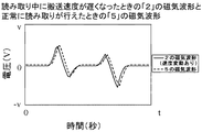
通常の磁気インク文字読み取り装置は単一トラックの磁気センサが検出した磁気データに対して、辞書テーブルに保持されているデータを比較することで、文字の判別を行い、その結果を出力する。図4は、E13Bフォントの一部である「2」と「5」について、通常の単一トラックの磁気センサで読み取った際の磁気波形の一例を示している。実線で示された波形が「2」の波形、点線で示された波形が「5」の波形である。縦軸は出力電圧値であり、横軸は時間の経過を表す。磁気インク文字読み取り装置は、図4に示したような波形を解析することにより、認識結果を得る。ところで、図4で示した「2」と「5」は、E13Bにて非常に似た波形を持つ文字として知られている。この2つの波形において違うのは、ピーク位置(尾根、谷の部分)の時間軸の差のみである。磁気インク文字読み取り装置は、この時間軸の差を比較し、認識結果を出力する。 A normal magnetic ink character reading device compares characters held in a dictionary table with magnetic data detected by a single track magnetic sensor, thereby determining characters and outputting the result. FIG. 4 shows an example of a magnetic waveform when “2” and “5”, which are part of the E13B font, are read by a normal single-track magnetic sensor. The waveform indicated by the solid line is the waveform “2”, and the waveform indicated by the dotted line is the waveform “5”. The vertical axis represents the output voltage value, and the horizontal axis represents the passage of time. The magnetic ink character reading device obtains a recognition result by analyzing the waveform as shown in FIG. Incidentally, “2” and “5” shown in FIG. 4 are known as characters having very similar waveforms in E13B. The only difference between these two waveforms is the difference in the time axis of the peak positions (ridges and valleys). The magnetic ink character reading device compares the time axis difference and outputs a recognition result.
しかしながら、「2」の読み取り途中に搬送速度が遅くなった場合、「2」の磁気波形は図5に示すように、ピーク位置(尾根、谷の部分)が「5」の磁気波形と非常に似た波形となる。したがって、速度変動により図5に示すように間延びした「2」の磁気読取波形になると、磁気インク文字読み取り装置は、「2」の文字であるのに、「5」の文字と判別してしまい、誤読が発生する。同様に、「5」の読み取り中に搬送速度が速くなった場合にも、「2」の文字と誤読する可能性がある。 However, when the conveyance speed is reduced during the reading of “2”, the magnetic waveform of “2” is very different from the magnetic waveform of “5” in the peak position (ridges and valleys) as shown in FIG. Similar waveform. Accordingly, when the magnetic reading waveform of “2” extended as shown in FIG. 5 due to the speed fluctuation is obtained, the magnetic ink character reading device determines that it is the character of “5” although it is the character of “2”. Misreading occurs. Similarly, when the conveyance speed increases during reading “5”, there is a possibility that the character “2” is misread.
次に、磁気インク文字読取装置で未読が起こる例を以下で説明する。上記で述べた誤読を起こす場合の例と同様に、文字の読み取り中に搬送速度が変動すると、得られる磁気波形のピーク位置が変動する。磁気インク文字読取装置は、磁気波形のピーク位置を解析して文字を判別するため、辞書データに保持されているデータの中に、得られた磁気波形と一致するものがない場合は未読となる。 Next, an example in which unreading occurs in the magnetic ink character reading device will be described below. Similar to the above-described example of misreading, if the conveyance speed fluctuates during character reading, the peak position of the obtained magnetic waveform fluctuates. Since the magnetic ink character reader analyzes the peak position of the magnetic waveform and discriminates the character, it is unread if there is no data that matches the obtained magnetic waveform in the data held in the dictionary data. .
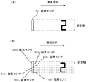
この誤読と未読が発生するという課題の解決のため、複数個の磁気センサを手形の搬送方向に対して直交させて配置し、各磁気センサの走査幅を単一トラックの磁気センサから構成されるものと比べて小さくし、MICR文字を各磁気センサが部分的に走査することを想定すると、図6(A)が「2」の磁気波形、図6(B)が「5」の磁気波形となる。それぞれの磁気センサで読み取った磁気波形同士を比較すると異なる特徴があることがわかる。これらの特徴から文字を判別できると考えられるが、磁気センサの数だけ文字判別処理を行うことになり、判別にかかる処理時間が増加し、磁気インク文字読み取り装置の読み取り処理速度が低下する可能性がある。 In order to solve the problem of misreading and unreading, a plurality of magnetic sensors are arranged perpendicular to the bill conveyance direction, and the scanning width of each magnetic sensor is composed of a single track magnetic sensor. Assuming that each magnetic sensor partially scans the MICR characters with a smaller size than that of FIG. 6, FIG. 6A shows a magnetic waveform of “2”, and FIG. Become. When the magnetic waveforms read by the respective magnetic sensors are compared, it can be seen that there are different characteristics. Although it is considered that characters can be distinguished from these features, character discrimination processing is performed as many as the number of magnetic sensors, which may increase the processing time required for the discrimination and reduce the reading processing speed of the magnetic ink character reader There is.
本発明の目的は、手形に印字されている磁気情報を正確に読み取ることができる磁気インク文字読み取り装置を提供することにある。また、高速の磁気インク文字読み取り装置を提供することにある。 An object of the present invention is to provide a magnetic ink character reading device capable of accurately reading magnetic information printed on a bill. Another object is to provide a high-speed magnetic ink character reading device.
上記目的を達成するために、本発明の磁気インク文字読取装置は、シートを搬送路に搬送させるための搬送手段と、前記搬送路に搬送されたシートに印字されている磁気印字情報を検出するための単一の磁気センサを有する第1検出手段と、前記磁気印字情報を検出するための複数の磁気センサを有する第2検出手段と、前記第2検出手段による検出を行うか否かを前記第1検出手段の検出結果に基づき判断する判断手段を有することを特徴とする。 In order to achieve the above object, a magnetic ink character reader according to the present invention detects conveyance means for conveying a sheet to a conveyance path and magnetic printing information printed on the sheet conveyed to the conveyance path. First detection means having a single magnetic sensor for detection, second detection means having a plurality of magnetic sensors for detecting the magnetic printing information, and whether to perform detection by the second detection means It has a judging means for judging based on the detection result of the first detecting means.
また、本発明の磁気インク文字読取装置は、シートを搬送路に搬送させるための搬送手段と、前記搬送路に搬送されたシートに印字されている磁気印字情報を検出するための単一の磁気センサを有する第1検出手段と、前記磁気印字情報を検出するための複数の磁気センサを有する第2検出手段と、前記第1検出手段による検出と、前記第2検出手段による検出とのどちらを行うかをユーザ設定に基づき判断する判断手段を有することを特徴とする。 The magnetic ink character reader according to the present invention includes a conveying means for conveying a sheet to a conveying path, and a single magnet for detecting magnetic printing information printed on the sheet conveyed to the conveying path. Which of the first detection means having a sensor, the second detection means having a plurality of magnetic sensors for detecting the magnetic print information, the detection by the first detection means, and the detection by the second detection means It is characterized by having a judgment means for judging whether to do based on user setting.
本発明によれば、複数の磁気センサで磁気インク文字の判別を行うため、磁気インク文字を読み取る際の誤読・未読を低減できる。また、単一の磁気センサを用いた第1検出手段と複数の磁気センサを用いた第2検出手段を両方有する場合は、搬送速度の変動等によって、単一の磁気センサによる検出手段からの判別が誤読・未読を起こす可能性が高くても、複数の磁気センサを使用して検出を行うよう設定でき、磁気インク文字を読み取る際の誤読・未読を低減できる。 According to the present invention, since magnetic ink characters are discriminated by a plurality of magnetic sensors, it is possible to reduce misreading / unreading when reading magnetic ink characters. In addition, when both the first detection means using a single magnetic sensor and the second detection means using a plurality of magnetic sensors are provided, discrimination from the detection means by a single magnetic sensor due to fluctuations in the conveyance speed, etc. Even if there is a high possibility of misreading / unreading, it can be set to detect using a plurality of magnetic sensors, and misreading / unreading when reading magnetic ink characters can be reduced.
また、単一の磁気センサを用いた第1検出手段と複数の磁気センサを用いた第2検出手段とを併用して判別を行う場合は、磁気インク文字を読み取る際の誤読・未読を低減でき、かつ、単一の磁気センサを用いた第1検出手段による検出に近い読取速度で処理を行うことができる。 In addition, when the determination is performed using both the first detection unit using a single magnetic sensor and the second detection unit using a plurality of magnetic sensors, erroneous reading / unreading when reading magnetic ink characters can be reduced. In addition, the processing can be performed at a reading speed close to the detection by the first detection means using a single magnetic sensor.
以下に例示する本発明の実施の形態について図面を参照しながら説明する。以下の実施例では、MICR文字(磁気印字情報)をE13Bのフォントとして説明する。図7に、E13Bフォントの文字の一覧を示す。 Embodiments of the present invention exemplified below will be described with reference to the drawings. In the following examples, MICR characters (magnetic printing information) are described as E13B fonts. FIG. 7 shows a list of characters in the E13B font.
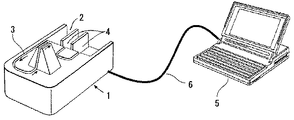
図2は本発明による磁気インク文字読取装置の第1の実施例の外観を示す斜視図である。磁気インク文字読取装置1には、手形(シート)を積載する為のホッパー部2が設けられている。3は手形を搬送する搬送路であり、ホッパー部2から排出口4まで溝状に形成されている。ホッパー部2に積載された手形は、図示しない搬送機構により1枚ずつ搬送路3を通り、搬送路中に設けられた磁気センサにより磁気情報が読み取られる。なお、排出口4は2箇所設けられ、正常にMICR文字を読めたかどうかの振り分け条件に応じて手形は2つの排出口4に振り分けられる。また、磁気インク文字読取装置1は、ホストPC5とUSBケーブルやSCSIケーブル等のケーブル6を介して接続されている。
FIG. 2 is a perspective view showing the appearance of the first embodiment of the magnetic ink character reader according to the present invention. The magnetic
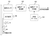
図8は本発明の磁気インク文字読取処理部の構成を示すブロック図である。搬送路3上には、搬送路の上流から、紙検知センサ10、永久磁石100、磁気センサ101、図1(B)のように配置された6個の磁気センサ201a〜201fの順番で配置されている。搬送方向Dは手形90の搬送方向を示す。磁気センサ101、磁気センサ201a〜201fとしては磁気ヘッド、磁気抵抗素子、磁気インピーダンス素子、ホール素子等が使用可能である。永久磁石100は、磁気センサ101、磁気センサ201a〜201fによって読み取られるMICR文字の磁化方向を整えるためのものであり、磁気信号のS/N比を出来るだけ良くする磁化方向に、搬送路3を搬送されてきた手形90に印字されているMICR文字の磁化を揃える。なお、永久磁石100はMICR文字の磁化を行うのが目的である為、電磁石を用いても構わない。図9は手形の一例を示す。手形90には、図9に示すように所定の領域91にMICR文字等が磁気インクや磁気トナーによって印字されている。
FIG. 8 is a block diagram showing the configuration of the magnetic ink character reading processing unit of the present invention. On the conveyance path 3, the paper detection sensor 10, the permanent magnet 100, the
本発明の実施例に係る磁気インク文字読取動作を図10のフローチャートを用いて説明する。本処理は磁気インク文字読取装置を制御する不図示のCPUにおいて実行されるソフトウエアによって実現しているが、その一部又は全てをハードウエアによって実現するようにしてもよい。はじめに、ホストPC5から、ケーブル6を介して手形の読み取り指示を行うと本処理が開始される。手形の読み取り指示の際に、ユーザは、読み取り処理速度を重視して単一の磁気センサを用いてMICR文字の認識を行うか、読み取った文字の信頼性を重視して複数の磁気センサを用いてMICR文字の認識を行うかをユーザ設定しておくものとする。本処理を開始すると、手形90を搬送路3上の図示しない搬送手段によって搬送し、紙検知センサ10によって、手形90の先端を検知する。
The magnetic ink character reading operation according to the embodiment of the present invention will be described with reference to the flowchart of FIG. This processing is realized by software executed by a CPU (not shown) that controls the magnetic ink character reading device, but part or all of the processing may be realized by hardware. First, when a bill reading instruction is issued from the
処理を開始した磁気インク文字読み取り装置1の不図示のCPUは、ユーザがホストPC5にて設定した設定情報に基づき単一の磁気センサ(第1検出手段)101を使用するか複数の磁気センサ(第2検出手段)201a〜201fを使用するかをステップS1001で判断(判断手段)し、単一の磁気センサを使用する設定であれば、ステップS1002〜S1004の処理を行い、複数の磁気センサを使用する設定であれば、ステップS1005〜S1007を行うように分岐する。
The CPU (not shown) of the magnetic ink
まず、単一の磁気センサを用いるようにユーザにより設定された場合の処理について説明する。搬送された手形90は永久磁石100を通過する際にMICR文字が磁化され、その後、磁気センサ101に到達する。ステップS1002では、手形90に印字されているMICR文字が通過する際に起きる磁束の変化を磁気ヘッド等の磁気センサ101で検知し、磁束の変化に対応して出力した出力信号に対して、増幅処理、フィルタ処理、AD変換を磁気データ処理部102で行い、AD変換後の磁気データを磁気データ判別部(第1検出手段)301で保持する。なお、磁気インピーダンス素子等のセンサでは、磁束の量に略比例した出力信号となるが、出力信号を微分して磁束の変化に対応した出力信号である磁気ヘッド等の出力信号波形に合わせてもよいし、そのままの波形を磁気インピーダンス素子等のセンサ用の基準波形と比較してもよい。
First, processing when the user sets to use a single magnetic sensor will be described. When the conveyed
ステップS1003では、ステップS1002で磁気データ判別部301に保持した磁気センサ101の出力信号に基づく磁気データ処理部102からのAD変換後の磁気データを一文字ごとに切り分ける。一文字ごとの切り分け方は、例えば特開平03−216781号公報に開示されているE13Bフォントの文字の先頭端読取り方法のように、文字の先頭端に対応する信号が必ず正ピークから始まることを利用して、文字の先頭を検出し、さらにサンプリング周期から文字幅を算出する方法がある。ただし、文字の切り分け方法は、他の方法を使用してもかまわない。
In step S1003, the magnetic data after AD conversion from the magnetic
不図示のCPU(比較手段、判別手段)はステップS1004では、ステップS1003で一文字ごとに切り分けた磁気データと辞書テーブル302に保持しているデータを比較することで、文字を判別する。本実施例で用いているE13Bフォントのそれぞれの文字は、磁気センサで読み取ったときに得られる波形を8等分に分割すると、磁気波形のピーク位置が異なるブロックに存在するように構成されている。そこで、文字の判別は、切り分けられた一文字分の幅を時間軸に対して8等分に分割し、磁気波形のピーク位置がどのブロックに存在するかを辞書テーブル302と比較し、判別する方法を用いる。 In step S1004, a CPU (not shown) (comparison means, discrimination means) discriminates characters by comparing the magnetic data segmented for each character in step S1003 with the data held in the dictionary table 302. Each character of the E13B font used in this embodiment is configured such that when the waveform obtained when read by the magnetic sensor is divided into eight equal parts, the peak position of the magnetic waveform exists in different blocks. . Therefore, the character is discriminated by dividing the width of one character divided into eight equal parts with respect to the time axis, and comparing with which block the peak position of the magnetic waveform exists in the dictionary table 302. Is used.
ステップS1008では、磁気データ判別部301からの判別結果を出力する。ステップS1009では、正常にMICR文字を読み取れたかどうかにより手形90を2つの排紙口に振り分け、読み取り処理を終了する。
In step S1008, the determination result from the magnetic
次に、複数の磁気センサ(第2検出手段)201a〜201fを用いるように設定された場合の処理について説明する。搬送された手形90は、永久磁石100を通過する際にMICR文字が磁化され、磁気センサ101を通過後、磁気センサ201a〜201fに到達する。
Next, processing in a case where setting is made to use a plurality of magnetic sensors (second detection means) 201a to 201f will be described. When the conveyed
ステップS1005では、手形90に印字されているMICR文字が通過する際に起きる磁束の変化を複数の磁気センサ201a〜201fで検知し、各磁気センサが検知した磁束の変化に対してそれぞれ、増幅処理、フィルタ処理、AD変換を磁気データ処理部202a〜202fで行い、AD変換後の各データを磁気データ判別部(第2検出手段)301で保持する。ステップS1006では、ステップS1005で磁気データ判別部301に保持した磁気センサ201a〜201fの出力信号に基づく磁気データ処理部202a〜202fからのAD変換後の磁気データを一文字ごとにそれぞれ切り分ける。一文字ごとの切り分け方は、前述のステップS1003で述べたものと同様の処理を各磁気データに対して行う。
In step S1005, a change in magnetic flux that occurs when the MICR characters printed on the
不図示のCPU(比較手段、判別手段)はステップS1007では、ステップS1006で一文字ごとに切り分けた各磁気データと辞書テーブル302に保持しているデータを比較することで、文字を判別する。文字判別方法は、前述のステップS1004で述べたものと同様の、以下のような処理を各磁気データに対して行う。 In step S1007, a CPU (not shown) (comparison means, discrimination means) discriminates characters by comparing each magnetic data segmented for each character in step S1006 with data held in the dictionary table 302. In the character discrimination method, the following processing similar to that described in step S1004 is performed on each magnetic data.
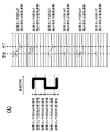
図6に6個の磁気センサを搬送方向に対して直交させて配置したときの「2」と「5」を読み取った時の各磁気センサから得られる磁気波形の例を示す。図6(A)が「2」の磁気波形、図6(B)が「5」の磁気波形であり、それぞれの磁気センサで読み取った磁気波形同士を比較すると異なる特徴があることがわかる。 FIG. 6 shows an example of a magnetic waveform obtained from each magnetic sensor when “2” and “5” are read when six magnetic sensors are arranged orthogonal to the transport direction. FIG. 6A shows the magnetic waveform “2” and FIG. 6B shows the magnetic waveform “5”. It can be seen that the magnetic waveforms read by the respective magnetic sensors have different characteristics.
具体的には、「2」の磁気波形は、磁気センサ201aから得られた磁気波形の初めのピーク(図6(A)のg地点)と磁気センサ201eから得られた磁気波形の初めのピーク(図6(A)のi地点)の時間軸の位置が同じであり、磁気センサ201bから得られた磁気波形の初めのピーク(図6(A)のh地点)の時間軸の位置が、gおよびi地点と異なる。それに対して、「5」の磁気波形は、磁気センサ201aから得られた磁気波形の初めのピーク(図6(B)のj地点)と磁気センサ201bから得られた磁気波形の初めのピーク(図6(B)のk地点)の時間軸の位置が同じであり、磁気センサ201eから得られた磁気波形の初めのピーク(図6(A)のl地点)の時間軸の位置が、jおよびk地点と異なる。このように、複数の磁気センサで読み取ると、単一の磁気センサで読み取る場合とは異なる磁気波形の特徴が表れ、正確な読み取りが可能となる。
Specifically, the magnetic waveform of “2” includes the first peak of the magnetic waveform obtained from the
ステップS1008では、磁気データ判別部301からの判別結果を出力する。ステップS1009では、正常にMICR文字を読み取れたかどうかにより手形90を2つの排紙口に振り分け、読取処理を終了する。
In step S1008, the determination result from the magnetic
このように、単一の磁気センサ101からのMICR文字認識と複数の磁気センサ201a〜201fからのMICR文字認識ができる磁気インク文字読み取り装置において、磁気センサ101からのMICR文字認識を行うか、磁気センサ201a〜201fからのMICR文字認識を行うかを設定できることによって、読み取り処理速度を重視した処理を行うか、読み取った文字の信頼性を重視した処理を行うかを任意にユーザが設定できる磁気インク文字読取装置を実現することができる。
In this way, in the magnetic ink character reader that can recognize the MICR characters from the single
本発明の第2の実施例に係る磁気インク文字読み取りの動作を図11のフローチャートを用いて説明する。なお、磁気インク文字読み取り装置1の基本的構成は実施例1と同様である。
The magnetic ink character reading operation according to the second embodiment of the present invention will be described with reference to the flowchart of FIG. The basic configuration of the magnetic ink
はじめに、ホストPC5から、ケーブル6を介して手形の読み取り指示があると磁気インク文字読み取り装置1は本処理を開始する。処理を開始した磁気インク文字読み取り装置1は、手形90を搬送路3上の図示しない搬送手段によって搬送する。そして、手形90の先端が紙検知センサ10によって検知され、永久磁石100を通過する際にMICR文字が磁化され、その後、手形90は磁気センサ101に到達する。次に、手形90に印字されているMICR文字が通過する際に起きる磁束の変化を磁気センサ101で検知し、磁束の変化に対応して出力した出力信号に対して、増幅処理、フィルタ処理、AD変換を磁気データ処理部102で行い、ステップS2001ではAD変換後のデータを磁気データ判別部301で保持する。なお実施例1で述べた変形例と同様に、磁束の変化ではなく、磁束の量に略比例した出力信号となる磁気センサを用いてもよい。
First, when there is a bill reading instruction from the
手形90は、磁気センサ101を通過後、磁気センサ201a〜201fに到達するので、手形90に印字されているMICR文字が通過する際に起きる磁束の変化を複数の磁気センサ201a〜201fで検知し、各磁気センサが検知した磁束の変化に対してそれぞれ、増幅処理、フィルタ処理、AD変換を磁気データ処理部202a〜202fで行い、ステップS2002では、AD変換後の各データを磁気データ判別部301で保持する。
Since the
ステップS2003では、ステップS2001で磁気データ判別部301に保持した磁気センサ101の出力信号に基づく磁気データ処理部102からのAD変換後の磁気データを一文字ごとに切り分ける。一文字ごとの切り分け方は、例えば特開平03−216781
号公報に開示されたE13Bフォントの文字の先頭端読取り方法のように、文字の開始が必ず正ピークから始まることを利用して、文字の先頭を検出し、さらにサンプリング周期から文字幅を算出することで、切り分けを行う。ただし、文字の切り分け方法は、他の方法を使用してもかまわない。
In step S2003, the magnetic data after AD conversion from the magnetic
As in the E13B font character leading edge reading method disclosed in Japanese Patent Publication No. Gazette, using the fact that the character start always starts from the positive peak, the character head is detected, and the character width is calculated from the sampling period. In this way, the carving is performed. However, other methods may be used for character separation.
ステップS2004では、ステップS2003で一文字ごとに切り分けた磁気データと辞書テーブル302に保持(記憶)しているデータを比較することで、文字を判別する。本実施例で用いているE13Bフォントのそれぞれの文字は、磁気センサで読み取ったときに得られる波形を時間軸方向に8等分に分割すると、磁気波形のピーク位置が異なるブロックに存在するように構成されている。そこで、文字の判別は、切り分けられた一文字分の幅を時間軸に対して8等分に分割し、磁気波形のピーク位置がどのブロックに存在するかを辞書テーブル302と比較し、判別する方法を用いる。 In step S2004, the character is discriminated by comparing the magnetic data carved for each character in step S2003 with the data held (stored) in the dictionary table 302. Each character of the E13B font used in this example is such that when the waveform obtained when read by the magnetic sensor is divided into eight equal parts in the time axis direction, the peak position of the magnetic waveform exists in different blocks. It is configured. Therefore, the character is discriminated by dividing the width of one character divided into eight equal parts with respect to the time axis, and comparing with which block the peak position of the magnetic waveform exists in the dictionary table 302. Is used.
不図示のCPU(判断手段)はステップS2005では、磁気センサ101で読み取った磁気波形による文字判別結果(検出結果)から、ステップS2006およびS2007の処理を行うかどうかの判断を、比較処理部303で行う。ステップS2006およびS2007を行う場合の判断基準は、磁気センサ101からの読み取りによる文字判別の結果として、MICR文字のフォントE13Bにおける「2」と「5」のように磁気波形が類似している文字であると判断したときと、未読のときである。不図示のCPU(判断手段)で行うこの判断のために、磁気波形が類似している文字は、あらかじめ比較処理部303に登録しておく。こうすることで、磁気波形が類似している特定の文字ではなく、かつ未読でないと判断したときは、ステップS2006およびS2007の処理を省略しステップS2008に進む。
In step S2005, a CPU (not shown) (not shown) determines whether to perform the processes in steps S2006 and S2007 from the character discrimination result (detection result) based on the magnetic waveform read by the
ステップS2005で磁気波形が類似している文字であるか、または未読であった場合は、ステップS2006およびS2007の処理を行う。ステップS2006では、ステップS2002で磁気データ判別部301に保持した磁気センサ201a〜201fの出力信号に基づく磁気データ処理部202a〜202fからのAD変換後の磁気データを一文字ごとにそれぞれ切り分ける。一文字ごとの切り分け方は、前述のステップS2003で述べたものと同様の処理を各磁気データに対して行う。
In step S2005, if the magnetic waveform is similar or unread, the processes in steps S2006 and S2007 are performed. In step S2006, the magnetic data after AD conversion from the magnetic
不図示のCPU(判別手段)はステップS2007では、ステップS2006で一文字ごとに切り分けた各磁気データと辞書テーブル302に保持しているデータを比較することで、文字を判別する。文字判別方法は、前述のステップS1007で述べたものと同様の処理を各磁気データに対して行う。 In step S2007, a CPU (not shown) (not shown) discriminates characters by comparing each magnetic data segmented for each character in step S2006 with data held in the dictionary table 302. In the character discrimination method, processing similar to that described in step S1007 is performed on each magnetic data.
ステップS2008では、ステップS2005での判断結果として、磁気波形の類似している文字と判断されておらず、かつ未読でない場合には、磁気センサ101からの判別結果を出力し、それ以外の場合には、磁気センサ201a〜201fからの判別結果を出力する。ステップS2009では、正常にMICR文字を読み取れたかどうかや、MICR文字による記述内容により手形90を2つの排紙口に振り分け、読み取り処理を終了する。
In step S2008, if the determination result in step S2005 is not determined to be a character with a similar magnetic waveform and is not unread, the determination result from the
MICR文字に対して全幅にわたって接触可能な幅を有する第1磁気センサ及び第2磁気センサをずらして設置し、一方をMICR文字に対して全幅(第1の所定領域)にわたって接触可能な位置に、他方をMICR文字の一部分(第2の所定領域)にわたって接触可能な位置に設置してもよい。両者の出力の差からMICR文字を判別可能であり、その方法は前述した方法に準じて行うようにすればよい。また、第1磁気センサ及び第2磁気センサの一方をMICR文字の略半分又はそれ以下(第1の所定領域)に接触可能な位置に設置し、他方をMICR文字の他の略半分又はそれ以下(第2の所定領域)に接触可能な位置に設置するようにしてもよい。なお、MICR文字に対して全幅にわたって接触可能な位置以外の位置に設置する磁気センサの幅は適宜狭めてもよい。 The first magnetic sensor and the second magnetic sensor having a width that can be contacted over the entire width with respect to the MICR character are installed by being shifted, and one of the magnetic sensors is placed at a position where the entire width (first predetermined region) can be contacted with respect to the MICR character. You may install the other in the position which can contact over a part (2nd predetermined area | region) of a MICR character. The MICR character can be discriminated from the difference between the two outputs, and the method may be performed in accordance with the method described above. Also, one of the first magnetic sensor and the second magnetic sensor is installed at a position where it can contact approximately half or less of the MICR character (first predetermined region), and the other is approximately half or less of the other MICR character. You may make it install in the position which can contact (2nd predetermined area | region). Note that the width of the magnetic sensor installed at a position other than the position where the entire width of the MICR character can be touched may be appropriately reduced.
なお、上記各実施例の構成要素を他の実施例に併用してもよい。各実施例においてMICR文字の判別等の処理や判断を磁気インク文字読取装置に接続されたホストPC等の外部装置で行うようにしてもよい。この場合、磁気インク文字読取装置と外部装置を含むシステムが本発明の磁気インク文字読取装置に相当する。 In addition, you may use the component of said each Example together with another Example. In each embodiment, processing such as MICR character determination and the like may be performed by an external device such as a host PC connected to the magnetic ink character reading device. In this case, a system including a magnetic ink character reading device and an external device corresponds to the magnetic ink character reading device of the present invention.
上記各実施例で説明したように、単一の磁気センサ101からの出力によるMICR文字認識と複数の磁気センサ201a〜201fからの出力によるMICR文字認識ができる磁気インク文字読取装置において、搬送速度の変動等によって、単一の磁気センサ101からの出力によるMICR文字認識で誤読や未読が起こりやすい状況でも、磁気センサ201a〜201fからのMICR文字認識を必要に応じて行うことで、誤読や未読を低減することができ、かつ、磁気センサ201a〜201fからのMICR文字認識が不要な場合は行わないため、従来の処理速度に近い磁気インク文字読取装置を実現することができる。
As described in the above embodiments, in a magnetic ink character reading apparatus capable of recognizing MICR characters by output from a single
1 磁気インク文字読取装置
2 ホッパー部
3 搬送路
4 排出口
5 ホストPC
6 ケーブル
10 紙検知センサ
90 手形
91 磁気文字印字エリア
100 永久磁石
101 磁気センサ
102 磁気データ処理部
103 磁気データ判別部
104 辞書データ
201a 磁気センサ
201b 磁気センサ
201c 磁気センサ
201d 磁気センサ
201e 磁気センサ
201f 磁気センサ
202a 磁気データ処理部
202b 磁気データ処理部
202c 磁気データ処理部
202d 磁気データ処理部
202e 磁気データ処理部
202f 磁気データ処理部
301 磁気データ判別部
302 辞書データ
303 比較処理部
DESCRIPTION OF
6 Cable 10
Claims (5)
前記搬送路に搬送されたシートに印字されている磁気印字情報を検出するための単一の磁気センサを有する第1検出手段と、
前記磁気印字情報を検出するための複数の磁気センサを有する第2検出手段と、
前記第2検出手段による前記複数の磁気センサの出力に基づく前記磁気印字情報の検出を行うか否かを前記第1検出手段の検出結果に基づき判断する判断手段を有すること
を特徴とする磁気インク文字読取装置。 Conveying means for conveying the sheet to the conveying path;
First detection means having a single magnetic sensor for detecting magnetic print information printed on a sheet conveyed to the conveyance path;
Second detection means having a plurality of magnetic sensors for detecting the magnetic printing information;
Magnetic ink, comprising: a determination unit configured to determine, based on a detection result of the first detection unit, whether to detect the magnetic print information based on outputs of the plurality of magnetic sensors by the second detection unit. Character reader.
前記搬送路に搬送されたシートに印字されている磁気印字情報を検出するための単一の磁気センサを有する第1検出手段と、
前記磁気印字情報を検出するための複数の磁気センサを有する第2検出手段と、
前記第1検出手段による前記磁気印字情報の検出と、前記第2検出手段による前記複数の磁気センサの出力に基づく前記磁気印字情報の検出とのどちらを行うかをユーザ設定に基づき判断する判断手段を有すること
を特徴とする磁気インク文字読み取り装置。 Conveying means for conveying the sheet to the conveying path;
First detection means having a single magnetic sensor for detecting magnetic print information printed on a sheet conveyed to the conveyance path;
Second detection means having a plurality of magnetic sensors for detecting the magnetic printing information;
Judgment means for judging whether to detect the magnetic print information by the first detection means or to detect the magnetic print information based on outputs of the plurality of magnetic sensors by the second detection means. A magnetic ink character reading device comprising:
を特徴とする請求項1に記載の磁気インク文字読取装置。 2. The magnetic print information is detected by the second detection unit with respect to the magnetic ink character when the first detection unit detects that the magnetic ink character is a specific character. The magnetic ink character reading device described in 1.
前記磁気印字情報を検出するための複数の磁気センサを有する第2検出手段と、
を有する磁気インク文字読取装置の制御方法であって、
前記第2検出手段による前記複数の磁気センサの出力に基づく前記磁気印字情報の検出を行うか否かを前記第1検出手段の検出結果に基づき判断する判別工程、を有することを特徴とする磁気インク文字読取装置の制御方法。 A first detecting unit having a single magnetic sensor for detecting magnetic printing information printed on the sheet conveyed to the conveying path;
Second detection means having a plurality of magnetic sensors for detecting the magnetic printing information;
A method for controlling a magnetic ink character reader having
And a determining step of determining whether to detect the magnetic print information based on the outputs of the plurality of magnetic sensors by the second detection means based on the detection result of the first detection means. Ink character reader control method.
Priority Applications (1)
| Application Number | Priority Date | Filing Date | Title |
|---|---|---|---|
| JP2009173919A JP2011028531A (en) | 2009-07-27 | 2009-07-27 | Magnetic ink character reading apparatus |
Applications Claiming Priority (1)
| Application Number | Priority Date | Filing Date | Title |
|---|---|---|---|
| JP2009173919A JP2011028531A (en) | 2009-07-27 | 2009-07-27 | Magnetic ink character reading apparatus |
Publications (1)
| Publication Number | Publication Date |
|---|---|
| JP2011028531A true JP2011028531A (en) | 2011-02-10 |
Family
ID=43637203
Family Applications (1)
| Application Number | Title | Priority Date | Filing Date |
|---|---|---|---|
| JP2009173919A Pending JP2011028531A (en) | 2009-07-27 | 2009-07-27 | Magnetic ink character reading apparatus |
Country Status (1)
| Country | Link |
|---|---|
| JP (1) | JP2011028531A (en) |
Cited By (2)
| Publication number | Priority date | Publication date | Assignee | Title |
|---|---|---|---|---|
| JP2018521477A (en) * | 2015-07-10 | 2018-08-02 | グルプラグGulplug | Electrical outlet assembly using electrical cutting method |
| WO2022018442A1 (en) * | 2020-07-21 | 2022-01-27 | Macon Management and Design Ltd | A magnetic pattern recognition sensor |
-
2009
- 2009-07-27 JP JP2009173919A patent/JP2011028531A/en active Pending
Cited By (3)
| Publication number | Priority date | Publication date | Assignee | Title |
|---|---|---|---|---|
| JP2018521477A (en) * | 2015-07-10 | 2018-08-02 | グルプラグGulplug | Electrical outlet assembly using electrical cutting method |
| WO2022018442A1 (en) * | 2020-07-21 | 2022-01-27 | Macon Management and Design Ltd | A magnetic pattern recognition sensor |
| GB2597443A (en) * | 2020-07-21 | 2022-02-02 | Macon Man And Design Ltd | A magnetic pattern recognition sensor |
Similar Documents
| Publication | Publication Date | Title |
|---|---|---|
| US8180137B2 (en) | Comparison of optical and magnetic character data for identification of character defect type | |
| JP2011227636A (en) | Character string recognition apparatus and character string recognition method | |
| JPWO2004081887A1 (en) | Paper sheet identification method and paper sheet identification apparatus | |
| EP2963621B1 (en) | Apparatus and method for recognizing media, financial device | |
| JP7018129B2 (en) | Paper leaf processing equipment and paper leaf processing method | |
| JP5502111B2 (en) | Paper sheet identification device and paper sheet identification method | |
| US9582713B2 (en) | Apparatus and method for recognizing media and financial device | |
| JP4880953B2 (en) | Paper sheet thickness discrimination device | |
| EP2431951A2 (en) | Sheet processing apparatus and sheet processing method | |
| JP2011028531A (en) | Magnetic ink character reading apparatus | |
| US8761487B2 (en) | Methods of operating an image-based check processing system to detect a double feed condition of checks and an apparatus therefor | |
| JP2017199326A (en) | Character reading device | |
| JP5697556B2 (en) | Paper sheet processing equipment | |
| US9129175B2 (en) | Recording media processing device, control method of a recording media processing device, and computer-readable recording medium | |
| JP4332414B2 (en) | Paper sheet handling equipment | |
| CN116092230B (en) | Ticket false identifying method and system | |
| US9047530B2 (en) | Recording media processing device, control method of a recording media processing device, and computer-readable recording medium storing a program | |
| EP4276780A1 (en) | Method of recognizing magnetic ink characters in atm | |
| US10652413B1 (en) | System and method for page set separation based on identifier on scanned page | |
| KR20090073681A (en) | Apparatus for magnetic ink character recognition and method for operating the same | |
| JP2011186848A (en) | Paper sheet processor and paper sheet processing method | |
| JP2004295359A (en) | Apparatus and method for reading magnetic data | |
| JP4654113B2 (en) | Paper sheet processing equipment | |
| JP2010079725A (en) | Magnetic ink character reader | |
| JP2004310346A (en) | Magnetic information reading method and device |