JP2011027196A - Ground-buried pressure resistant synthetic resin pipe - Google Patents
Ground-buried pressure resistant synthetic resin pipe Download PDFInfo
- Publication number
- JP2011027196A JP2011027196A JP2009174811A JP2009174811A JP2011027196A JP 2011027196 A JP2011027196 A JP 2011027196A JP 2009174811 A JP2009174811 A JP 2009174811A JP 2009174811 A JP2009174811 A JP 2009174811A JP 2011027196 A JP2011027196 A JP 2011027196A
- Authority
- JP
- Japan
- Prior art keywords
- pipe
- synthetic resin
- resistant synthetic
- pressure
- underground
- Prior art date
- Legal status (The legal status is an assumption and is not a legal conclusion. Google has not performed a legal analysis and makes no representation as to the accuracy of the status listed.)
- Pending
Links
Images


Abstract
Description
本発明は、上水管、下水(排水)管等に主として用いられる管に係り、より詳しくは、軽量で可撓性を有し、且つ十分な耐圧強度を備え、比較的口径の大きな下水道本管の更生の自立管工法にも使用できる地中埋設用耐圧合成樹脂管に関する。 The present invention relates to a pipe mainly used for a water pipe, a sewage (drainage) pipe, and the like, and more specifically, a sewer main having a relatively large diameter, being light and flexible, having sufficient pressure resistance. The present invention relates to a pressure-resistant synthetic resin pipe for underground burial that can be used in the self-supporting pipe construction method for rehabilitation of the earth.
下水道事業に多く使用されているコンクリート管については、近年、硫化水素による腐食が深刻化しており、耐用年数に満たない管でも漏水等の問題が発生している。現在採用されている老朽化した既設管の復旧工事の手法(管更生工法)としては、開削による既設管の取替え工事以外に、非開削の管更生工法として、光硬化工法や熱硬化工法、やや小径のフレキシブルな合成樹脂管を挿通し、管同士の隙間にモルタル等の充填材を注入して既設管と一体化させる工法などが挙げられるが、これら従来の管更生工法はいずれも手間やコストが掛かっていた。 In recent years, corrosion caused by hydrogen sulfide has become serious for concrete pipes that are widely used in sewerage projects, and even pipes that have less than their useful lives have problems such as water leakage. As a method for restoring existing pipes that have already been used (pipe rehabilitation method), in addition to exchanging existing pipes by excavation, non-open-cutting pipe rehabilitation methods such as photo-curing method and heat-curing method are used. There is a method of inserting a flexible synthetic resin pipe with a small diameter and injecting a filler such as mortar into the gap between the pipes to integrate it with the existing pipe, but these conventional pipe rehabilitation methods are both labor and cost It was hanging.
これに対し、本発明者は先に、既設管の内部に地中埋設用耐圧合成樹脂管を挿通し、管同士の隙間を両端部のみ封止してその他の中間部は充填材を埋め込まずにそのまま隙間がある状態とし、挿通した管自体を更生管として機能させる管更生工法(自立管工法)を提案している(特許文献1参照)。このような自立管工法に用いる管には、既設管が崩壊した後も十分な耐圧強度を有する自立性が要求される。同文献においては、このような自立管工法に適した更生管として、螺旋波形状の合成樹脂壁部の山部内側面に金属製補強線を同じく螺旋状に付設し、管壁内周側に内管壁を設けて山部との間に閉塞空間を形成した地中埋設用合成樹脂管をも提案している。このような管によれば、可撓性を有すると同時に、前記金属製補強線により可撓性を阻害することなく耐圧強度を高めることができる。 On the other hand, the present inventor first inserts a pressure-resistant synthetic resin tube for underground burial into the existing tube, seals the gap between the tubes only at both ends, and does not bury the filler in the other intermediate portions. A pipe rehabilitation method (self-supporting pipe construction method) is proposed in which there is a gap as it is and the inserted tube itself functions as a rehabilitation pipe (see Patent Document 1). The pipe used for such a self-supporting pipe construction method is required to have a self-supporting property having sufficient pressure resistance even after the existing pipe collapses. In this document, as a rehabilitation pipe suitable for such a self-supporting pipe construction method, a metal reinforcing wire is also spirally attached to the inner surface of the mountain portion of the synthetic resin wall part having a spiral wave shape, and the inner wall is formed on the inner peripheral side of the pipe wall. We have also proposed a synthetic resin pipe for underground use in which a closed space is formed between the pipe wall and the mountain. According to such a tube, it has flexibility, and at the same time, the pressure strength can be increased without impeding flexibility by the metal reinforcing wire.
しかしながら、上記特許文献1記載の地中埋設用合成樹脂管は、口径が大きくなるにしたがい耐圧強度が低下し、比較的口径の大きな自立管工法の更生管としては使用し難いという課題がある。狭いマンホール等から既設管へ引き込まれる更生管には、高い可撓性が要求されるため、通常、更生管自体に十分な耐圧強度を持たせることが困難である。このため、一般的な管構更生工法では、モルタル等の充填材で既設管と完全に一体化させ、これにより耐圧強度を維持している。自立管工法では、更生管に上記可撓性と同時に自立性を有する耐圧強度が要求されるため、更生管の開発は非常に難しい。
However, the underground synthetic resin pipe described in
そこで、本発明が前述の状況に鑑み、解決しようとするところは、優れた可撓性を有するとともに、口径が大きくなっても十分な耐圧強度を維持でき、比較的口径が大きい下水道本管などの自立管工法の更生管としても好適な地中埋設用耐圧合成樹脂管を提供する点にある。 Therefore, in view of the above-mentioned situation, the present invention is to solve the problem of having excellent flexibility and maintaining sufficient pressure resistance even when the caliber is increased, such as a sewer main having a relatively large caliber, etc. It is the point which provides the pressure-resistant synthetic resin pipe for underground burial suitable also as a rehabilitation pipe | tube of this self-supporting pipe construction method.
本発明者は、かかる現況に鑑み、鋭意検討した結果、高強度を有する地中埋設用耐圧合成樹脂管として公知の管であるが、内面がほぼフラットの本体部の外周側に補強凸部を螺旋状に設け、この補強凸部に金属薄板製の金属帯板を同じく螺旋状に配設した管に着目した。この管は、上水管、下水(排水)管等に主として用いられる管であり、金属帯板を配した螺旋状の補強凸部の存在により十分な耐圧強度を有し、本体部の材料を比較的柔らかい樹脂とすることである程度の可撓性を持たせているが、この可撓性は狭いマンホール等から既設管へ引き込まれる更生管に要求される高い可撓性を有しておらず、更生管としては従来用いられていない。本発明者は、この地中埋設用耐圧合成樹脂管の耐圧強度向上の要の構成部分である補強凸部の素材について、本来の耐圧強度の向上を担う部分の素材として矛盾するが、比較的柔らかい樹脂を用いることで、耐圧強度を十分に維持しつつ、全体の可撓性を著しく高めることができ、下水道本管などの自立管工法の更生管として好適に用いることができることを見出し、本発明を完成するに至った。 As a result of diligent examination in view of the present situation, the present inventor is a known pipe as a pressure-resistant synthetic resin pipe for underground burial having high strength, but a reinforcing convex part is provided on the outer peripheral side of the main body part whose inner surface is substantially flat. Attention was paid to a tube provided in a spiral shape and a metal strip made of a thin metal plate disposed in a spiral shape on the reinforcing convex portion. This pipe is mainly used for water pipes, sewage (drainage) pipes, etc., and has sufficient pressure resistance due to the presence of spiral reinforcing projections with metal strips. However, this flexibility does not have the high flexibility required for rehabilitation pipes drawn into existing pipes from narrow manholes, It has not been used as a rehabilitation tube. The present inventor contradicts the material of the reinforced convex portion, which is an essential component for improving the pressure strength of the underground pressure-resistant synthetic resin pipe, as the material of the portion responsible for the improvement of the original pressure strength, By using a soft resin, the overall flexibility can be remarkably enhanced while maintaining sufficient pressure strength, and it can be suitably used as a rehabilitation pipe for self-standing pipe construction methods such as sewer mains. The invention has been completed.
すなわち本発明は、内面がほぼフラットの本体部の外周側に補強凸部を螺旋状に設けてなる合成樹脂製の管壁を備え、且つ該管壁の前記補強凸部に金属薄板製の金属帯板を同じく螺旋状に配設してなる地中埋設用耐圧合成樹脂管において、前記金属帯板を有する補強凸部が、低密度ポリエチレン樹脂よりなることを特徴とする地中埋設用耐圧合成樹脂管を構成した。 That is, the present invention includes a synthetic resin tube wall having a spirally provided reinforcing convex portion on the outer peripheral side of a main body portion whose inner surface is substantially flat, and the reinforcing convex portion of the tube wall is made of a metal thin plate. A pressure-resistant synthetic resin tube for underground burying in which strips are similarly arranged in a spiral shape, wherein the reinforcing convex part having the metal strip is made of low-density polyethylene resin. A resin tube was constructed.
ここで、前記金属帯板が、外側に湾出した形状で前記補強凸部の形状に沿って配されるアーチ部と、その両側端部を管軸方向に略L字状に屈曲させて前記本体部側に配される一対の脚部とよりなるものが好ましい。 Here, the metal strip is bent in an approximately L shape in the tube axis direction with an arch portion arranged along the shape of the reinforcing convex portion in a shape protruding to the outside, and the both ends. What consists of a pair of leg part distribute | arranged to the main-body part side is preferable.
また、前記管壁の本体部が、同じく低密度ポリエチレン樹脂よりなるものが好ましい。 Moreover, it is preferable that the main body portion of the tube wall is made of a low density polyethylene resin.
また、既設管の内部に管を挿通し、既設管と挿通した管の隙間を両端部のみ封止してその他の中間部は充填材を埋め込まずにそのまま隙間がある状態として、挿通した管自体を更生管として機能させる管更生工法における前記挿通される管(更生管)としての用途に用いられるものが好ましい実施例である。 Also, the tube itself is inserted into the existing tube, the gap between the existing tube and the inserted tube is sealed only at both ends, and the other intermediate portion is left without any filling material, and there is a gap as it is. What is used for the use as the said pipe | tube (rehabilitation pipe | tube) penetrated in the pipe rehabilitation method which functions as a rehabilitation pipe | tube is a preferable Example.
以上にしてなる本願発明に係る地中埋設用耐圧合成樹脂管は、口径が大きくなっても十分な耐圧強度を維持できる優れた強度を備えるとともに、狭いマンホール等から既設管へ引き込まれる更生管としても使用できる優れた可撓性を備えることから、上水管や下水(排水)管として好適であることは勿論のこと、特に、比較的口径が大きい下水道本管などの自立管工法の更生管としても好適に使用することができる。また、従来の合成樹脂管の管厚を大きくして耐圧強度を高めたものと比較しても軽量で材料コストも安く、可撓性にも優れるため作業性に優れた管を提供できる。 The underground pressure-resistant synthetic resin pipe according to the present invention as described above has excellent strength capable of maintaining sufficient pressure-resistant strength even when the diameter is increased, and as a rehabilitation pipe drawn into an existing pipe from a narrow manhole or the like. As a rehabilitating pipe for self-standing pipe construction methods such as a sewer main pipe with a relatively large diameter, it is of course suitable for use as a water pipe or sewage (drainage) pipe. Can also be suitably used. In addition, compared with a conventional synthetic resin pipe having an increased thickness and increased pressure resistance, it is light in weight, has a low material cost, and is excellent in flexibility, so that a pipe excellent in workability can be provided.
次に、本発明の実施形態を添付図面に基づき詳細に説明する。 Next, embodiments of the present invention will be described in detail with reference to the accompanying drawings.
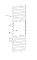
本発明に係る地中埋設用耐圧合成樹脂管1は、図1に示すように、内面がほぼフラットの本体部2の外周側に補強凸部3を螺旋状に設けた合成樹脂製の管壁10を備え、該管壁10の補強凸部3に、図2の拡大断面図に示すように金属薄板製の金属帯板4が同じく螺旋状に配設された構造を有している。そして、本発明は、前記金属帯板4を有する補強凸部3を、低密度ポリエチレン樹脂より構成したことを特徴としている。
As shown in FIG. 1, the underground pressure-resistant
より具体的には、本体部2を形成する平帯状の合成樹脂帯をその両側縁部分を重合させながら順次螺旋状に巻回し、その外周面上に、下向開放の略V字形ないしU字形でその両
開放端部をそれぞれ横方向に向けて突出させた突出縁を有する形状とした帯状の部分成形体を、その山部の内面に金属製補強線を融着一体化させながら順次、螺旋状に巻回し、前記突出縁を互いに重畳するようにして、前記本体部2の表面上に補強凸部3を一体的に融着して構成されている。補強凸部3の形状は上記した略V字形に限定されず、略コ字形な
どその他の形状に成形してもよい。また、本発明はこのような成形方法に何ら限定されず、例えば、部分成形体を左方の横外方突出縁を長く延長した構造とし、当該突出縁部分が補強凸部3の管軸側の周口部を閉塞し、連続した本体部2を構成する構造としてもよい。
More specifically, a flat strip-shaped synthetic resin band forming the
本体部2は、内面が略直円筒状に形成され、多少の凹凸波形を有するものとしてもよい。本発明では、補強凸部3に低密度ポリエチレン樹脂を用いている。本体部2には、ポリエチレンやポリプロピレン等のポリオレフィン系や塩化ビニル系等の合成樹脂が用いられるが、その他合成ゴムや軟質樹脂を用いてもよい。特に耐薬品性の点からポリエチレン樹脂を用いることが好ましく、より具体的には、本体部2も同じく低密度ポリエチレン樹脂を用いることが好ましい。勿論、その他の合成樹脂で構成することもできる。本体部2と補強凸部3をいずれも低密度ポリエチレン樹脂とすれば、両者の密着度が向上するとともに、両者を分けて成形することなく一体で効率よく押出成形することが可能となる。
The
金属帯板4は、図2に示すように、外側に湾出した形状で補強凸部3の形状に沿って配されるアーチ部40と、その両側端部を管軸方向に略L字状に屈曲させて本体部2側に配される一対の脚部41とを備えた金属薄板より構成されている。金属薄板は、小孔のない金属板以外に、板面に多数の小孔を貫設したパンチング板等でもよく、材料はステンレス薄板や鋼薄板のほか、鉄板を使用してもよく、そのほかの金属薄板を用いてもよい。
As shown in FIG. 2, the
この金属帯板4は、補強凸部3を形成する上記部分成形体に予め内装されるか、部分成形体の内側又は外側に付着一体化させた状態で本体部2表面に融着することにより、補強凸部3を構成している。金属帯板4を金属薄板の表裏に合成樹脂製の被覆層を備えたラミネート金属板としたうえで上記部分成形体に付着一体化させることが好ましい。また、部分成形体の代わりに、当該ラミネート金属板よりなる金属帯板4自体を補強凸部3としてもよい。ラミネート金属板を用いる場合における被覆層は、密着度の点から合成樹脂壁部と同様の素材で構成することが好ましく、例えばポリエチレン樹脂、ポリプロピレン樹脂等のポリオレフイン系樹脂からなるものが好ましい。特に低密度ポリエチレン樹脂からなるものとすれば、補強凸部3の部分成形体や本体部2の樹脂と同じに設定でき、密着度が向上するとともに、上記のとおり金属帯板4自体を補強凸部3として構成することが可能となる。
The
補強凸部3は、複数列設けてもよく、この場合、そのうちの一部の列にのみ金属帯板4を設けてもよい。また、補強凸部3のピッチは、従来の同様の構造の管に比べて広めに設定し、可撓性をより高めたものが好ましい実施例である。
The reinforcing
次に、図3及び図4に基づき、本実施形態の地中埋設用耐圧合成樹脂管1を用いた管更生工法について説明する。
Next, based on FIG.3 and FIG.4, the pipe renovation method using the underground pressure-resistant
本例では、マンホール81、82間に下水道本管(ヒューム管)である既設管9が設けられており、これを更生する方法を説明する。尚、本発明に係る地中埋設用耐圧合成樹脂管1は、このような下水道等の本管以外に枝管や家の宅桝と下水本管の間の管、その他の既設管の更生に広く適用できることは勿論である。既設管9の更生のため、地中埋設用耐圧合成樹脂管1を既設管9内に一方のマンホール81側から内部に挿通し、両管の隙間については、排水が流入しないように、両端部91、92のみ封止する管口処理だけで済み、両管を完全に一体化する必要はない。
In this example, the existing
即ち、その他の中間部93は、従来の工法であればモルタル等の充填材を充填して既設管9と更生管とを一体化させる必要があったが、本発明の地中埋設用耐圧合成樹脂管1は、それ自体優れた耐圧強度を有しており、既設管9が破損しても土圧を支持する十分な耐久性を有している為、そのまま隙間がある状態とし、地中埋設用耐圧合成樹脂管1自体を独立の排水管として機能させることができるのである。
That is, the other
端部の封止は、本例では、図4に示すようにソケット部材7を装着して、隙間端部をきわめて容易に封止可能とされている。ソケット部材7は、地中埋設用耐圧合成樹脂管1の端部外周に螺合して既設管9との隙間を塞ぐ筒状部70と、既設管9の端面91aに当接するフランジ部71とより構成されており、筒状部70の内周面には、地中埋設用耐圧合成樹脂管1の管壁外面に螺合するネジ溝70bが設けられている。他端部は、隙間に充填材を部分的に詰めて水密状に封止される。このソケット部材7を排水上流のマンホール側に装着すれば、施工が容易であるとともに排水の隙間への浸入を確実に防止できる。本例のような自立管工法によれば、このようなソケット部材7を用いた簡単な端部の封止のみで管更生を行うことができ、工期短縮、経費削減に貢献でき、本発明に係る地中埋設用耐圧合成樹脂管1を自立管工法の更生管として用いることで、狭いマンホール内においても端部の封止作業を効率よく行うことができる。
In this example, the end portion is sealed by attaching the
以上、本発明の実施形態について説明したが、本発明はこうした実施例に何ら限定されるものではなく、本発明の要旨を逸脱しない範囲において種々なる形態で実施し得ることは勿論である。 Although the embodiments of the present invention have been described above, the present invention is not limited to these embodiments, and can of course be implemented in various forms without departing from the gist of the present invention.
1 地中埋設用耐圧合成樹脂管
2 本体部
3 補強凸部
4 金属帯板
7 ソケット部材
9 既設管
10 管壁
40 アーチ部
41 脚部
70 筒状部
70b ネジ溝
71 フランジ部
81 マンホール
91 端部
91a 端面
93 中間部
DESCRIPTION OF
Claims (4)
前記金属帯板を有する補強凸部が、低密度ポリエチレン樹脂よりなることを特徴とする地中埋設用耐圧合成樹脂管。 A tube wall made of synthetic resin is provided on the outer peripheral side of the main body portion having a substantially flat inner surface, and a reinforcing resin spirally provided on the outer peripheral side, and a metal strip made of a thin metal plate is also spiraled on the reinforcing convex portion of the tube wall. In the underground pressure-resistant synthetic resin pipe arranged in a shape,
A pressure-resistant synthetic resin tube for underground embedment, wherein the reinforcing convex part having the metal strip is made of low-density polyethylene resin.
Priority Applications (1)
| Application Number | Priority Date | Filing Date | Title |
|---|---|---|---|
| JP2009174811A JP2011027196A (en) | 2009-07-27 | 2009-07-27 | Ground-buried pressure resistant synthetic resin pipe |
Applications Claiming Priority (1)
| Application Number | Priority Date | Filing Date | Title |
|---|---|---|---|
| JP2009174811A JP2011027196A (en) | 2009-07-27 | 2009-07-27 | Ground-buried pressure resistant synthetic resin pipe |
Publications (1)
| Publication Number | Publication Date |
|---|---|
| JP2011027196A true JP2011027196A (en) | 2011-02-10 |
Family
ID=43636173
Family Applications (1)
| Application Number | Title | Priority Date | Filing Date |
|---|---|---|---|
| JP2009174811A Pending JP2011027196A (en) | 2009-07-27 | 2009-07-27 | Ground-buried pressure resistant synthetic resin pipe |
Country Status (1)
| Country | Link |
|---|---|
| JP (1) | JP2011027196A (en) |
Cited By (1)
| Publication number | Priority date | Publication date | Assignee | Title |
|---|---|---|---|---|
| JP6084743B1 (en) * | 2016-08-05 | 2017-02-22 | 東拓工業株式会社 | Continuous production method of resin metal composite pipe |
Citations (5)
| Publication number | Priority date | Publication date | Assignee | Title |
|---|---|---|---|---|
| JPS6479492A (en) * | 1988-08-25 | 1989-03-24 | Shiro Kanao | Pressure-resistant synthetic resin pipe for underground burying |
| JPH0611076A (en) * | 1992-02-25 | 1994-01-21 | Shiro Kanao | Pressure proof helical corrugated pipe |
| JPH06174154A (en) * | 1992-12-09 | 1994-06-24 | Shiro Kanao | Pressure proof synthetic resin pipe |
| JP2006177496A (en) * | 2004-12-24 | 2006-07-06 | Inoac Corp | Corrugated tube |
| JP2008303970A (en) * | 2007-06-07 | 2008-12-18 | Kanaflex Corporation | Ground-buried pressure resistant synthetic resin pipe and pipe reclaiming technique using the same |
-
2009
- 2009-07-27 JP JP2009174811A patent/JP2011027196A/en active Pending
Patent Citations (5)
| Publication number | Priority date | Publication date | Assignee | Title |
|---|---|---|---|---|
| JPS6479492A (en) * | 1988-08-25 | 1989-03-24 | Shiro Kanao | Pressure-resistant synthetic resin pipe for underground burying |
| JPH0611076A (en) * | 1992-02-25 | 1994-01-21 | Shiro Kanao | Pressure proof helical corrugated pipe |
| JPH06174154A (en) * | 1992-12-09 | 1994-06-24 | Shiro Kanao | Pressure proof synthetic resin pipe |
| JP2006177496A (en) * | 2004-12-24 | 2006-07-06 | Inoac Corp | Corrugated tube |
| JP2008303970A (en) * | 2007-06-07 | 2008-12-18 | Kanaflex Corporation | Ground-buried pressure resistant synthetic resin pipe and pipe reclaiming technique using the same |
Cited By (2)
| Publication number | Priority date | Publication date | Assignee | Title |
|---|---|---|---|---|
| JP6084743B1 (en) * | 2016-08-05 | 2017-02-22 | 東拓工業株式会社 | Continuous production method of resin metal composite pipe |
| WO2018025454A1 (en) * | 2016-08-05 | 2018-02-08 | 東拓工業株式会社 | Method for continuously producing resin-metal composite pipe, and resin-metal composite pipe resulting from said production method |
Similar Documents
| Publication | Publication Date | Title |
|---|---|---|
| WO2012014336A1 (en) | Pipeline regeneration pipe | |
| JP2011027196A (en) | Ground-buried pressure resistant synthetic resin pipe | |
| CN112879682A (en) | Spiral winding composite underground pipeline | |
| KR100426405B1 (en) | Drainage channel pipe connection device, especially facilitating use in curved part according to structure of construction spot | |
| JP2006316539A (en) | Repairing structure of existing pipe | |
| JP5588255B2 (en) | Pipe line rehabilitation pipe | |
| JP2008303970A (en) | Ground-buried pressure resistant synthetic resin pipe and pipe reclaiming technique using the same | |
| JP3176082U (en) | Pipeline rehabilitation pipe | |
| KR20120126257A (en) | A coupler for connecting drain pipe | |
| JP2011027197A (en) | Pressure tube for fluid | |
| KR101086666B1 (en) | One-touch connector for double wall pipe | |
| KR101641114B1 (en) | Manholes equipped with pipe connectors | |
| JP5567917B2 (en) | Cable conduit | |
| KR970009012B1 (en) | Reinforcement plastic pipe | |
| JP2021011904A (en) | Underground burial fiber compound resin pipe, pipe regeneration structure and pipe regeneration method | |
| KR101904311B1 (en) | Angle control type concrete manhole of flow velocity holding structure | |
| KR102268285B1 (en) | Leak preventive T shaped corrugated socket assembly | |
| KR100915950B1 (en) | method for connecting a tube of underground cable to the other | |
| KR100598898B1 (en) | Connector of sewage pipe for houses | |
| JP3199492B2 (en) | Spiral tube for existing pipe lining | |
| CN210510602U (en) | Socket joint formula drain pipe | |
| KR102268287B1 (en) | Leak preventive corrugated socket assembly | |
| KR20190045632A (en) | pipe connector | |
| JP2006274535A (en) | Repair structure of existing pipeline | |
| KR20210130573A (en) | Concrete manhole that can maintain the flow rate |
Legal Events
| Date | Code | Title | Description |
|---|---|---|---|
| RD03 | Notification of appointment of power of attorney |
Free format text: JAPANESE INTERMEDIATE CODE: A7423 Effective date: 20110325 |
|
| RD04 | Notification of resignation of power of attorney |
Free format text: JAPANESE INTERMEDIATE CODE: A7424 Effective date: 20110328 |
|
| RD04 | Notification of resignation of power of attorney |
Free format text: JAPANESE INTERMEDIATE CODE: A7424 Effective date: 20110328 |
|
| A621 | Written request for application examination |
Free format text: JAPANESE INTERMEDIATE CODE: A621 Effective date: 20120720 |
|
| A977 | Report on retrieval |
Free format text: JAPANESE INTERMEDIATE CODE: A971007 Effective date: 20130823 |
|
| A131 | Notification of reasons for refusal |
Free format text: JAPANESE INTERMEDIATE CODE: A131 Effective date: 20130910 |
|
| A02 | Decision of refusal |
Free format text: JAPANESE INTERMEDIATE CODE: A02 Effective date: 20140128 |