JP2011025026A - Exercise apparatus - Google Patents
Exercise apparatus Download PDFInfo
- Publication number
- JP2011025026A JP2011025026A JP2010155300A JP2010155300A JP2011025026A JP 2011025026 A JP2011025026 A JP 2011025026A JP 2010155300 A JP2010155300 A JP 2010155300A JP 2010155300 A JP2010155300 A JP 2010155300A JP 2011025026 A JP2011025026 A JP 2011025026A
- Authority
- JP
- Japan
- Prior art keywords
- support plate
- movement
- support
- instrument
- track
- Prior art date
- Legal status (The legal status is an assumption and is not a legal conclusion. Google has not performed a legal analysis and makes no representation as to the accuracy of the status listed.)
- Pending
Links
Images


Classifications
-
- A—HUMAN NECESSITIES
- A63—SPORTS; GAMES; AMUSEMENTS
- A63B—APPARATUS FOR PHYSICAL TRAINING, GYMNASTICS, SWIMMING, CLIMBING, OR FENCING; BALL GAMES; TRAINING EQUIPMENT
- A63B22/00—Exercising apparatus specially adapted for conditioning the cardio-vascular system, for training agility or co-ordination of movements
- A63B22/20—Exercising apparatus specially adapted for conditioning the cardio-vascular system, for training agility or co-ordination of movements using rollers, wheels, castors or the like, e.g. gliding means, to be moved over the floor or other surface, e.g. guide tracks, during exercising
- A63B22/201—Exercising apparatus specially adapted for conditioning the cardio-vascular system, for training agility or co-ordination of movements using rollers, wheels, castors or the like, e.g. gliding means, to be moved over the floor or other surface, e.g. guide tracks, during exercising for moving a support element in reciprocating translation, i.e. for sliding back and forth on a guide track
- A63B22/203—Exercising apparatus specially adapted for conditioning the cardio-vascular system, for training agility or co-ordination of movements using rollers, wheels, castors or the like, e.g. gliding means, to be moved over the floor or other surface, e.g. guide tracks, during exercising for moving a support element in reciprocating translation, i.e. for sliding back and forth on a guide track in a horizontal plane
-
- A—HUMAN NECESSITIES
- A63—SPORTS; GAMES; AMUSEMENTS
- A63B—APPARATUS FOR PHYSICAL TRAINING, GYMNASTICS, SWIMMING, CLIMBING, OR FENCING; BALL GAMES; TRAINING EQUIPMENT
- A63B21/00—Exercising apparatus for developing or strengthening the muscles or joints of the body by working against a counterforce, with or without measuring devices
- A63B21/06—User-manipulated weights
- A63B21/0609—User-manipulated weights consisting of loosely interconnected elements for progressively changing weight, e.g. heavy chains
-
- A—HUMAN NECESSITIES
- A63—SPORTS; GAMES; AMUSEMENTS
- A63B—APPARATUS FOR PHYSICAL TRAINING, GYMNASTICS, SWIMMING, CLIMBING, OR FENCING; BALL GAMES; TRAINING EQUIPMENT
- A63B21/00—Exercising apparatus for developing or strengthening the muscles or joints of the body by working against a counterforce, with or without measuring devices
- A63B21/06—User-manipulated weights
- A63B21/0618—User-manipulated weights moving in a horizontal plane without substantial friction, i.e. using inertial forces
-
- A—HUMAN NECESSITIES
- A63—SPORTS; GAMES; AMUSEMENTS
- A63B—APPARATUS FOR PHYSICAL TRAINING, GYMNASTICS, SWIMMING, CLIMBING, OR FENCING; BALL GAMES; TRAINING EQUIPMENT
- A63B21/00—Exercising apparatus for developing or strengthening the muscles or joints of the body by working against a counterforce, with or without measuring devices
- A63B21/06—User-manipulated weights
- A63B21/062—User-manipulated weights including guide for vertical or non-vertical weights or array of weights to move against gravity forces
- A63B21/0626—User-manipulated weights including guide for vertical or non-vertical weights or array of weights to move against gravity forces with substantially vertical guiding means
- A63B21/0628—User-manipulated weights including guide for vertical or non-vertical weights or array of weights to move against gravity forces with substantially vertical guiding means for vertical array of weights
-
- A—HUMAN NECESSITIES
- A63—SPORTS; GAMES; AMUSEMENTS
- A63B—APPARATUS FOR PHYSICAL TRAINING, GYMNASTICS, SWIMMING, CLIMBING, OR FENCING; BALL GAMES; TRAINING EQUIPMENT
- A63B22/00—Exercising apparatus specially adapted for conditioning the cardio-vascular system, for training agility or co-ordination of movements
- A63B22/0002—Exercising apparatus specially adapted for conditioning the cardio-vascular system, for training agility or co-ordination of movements involving an exercising of arms
- A63B22/001—Exercising apparatus specially adapted for conditioning the cardio-vascular system, for training agility or co-ordination of movements involving an exercising of arms by simultaneously exercising arms and legs, e.g. diagonally in anti-phase
- A63B22/0012—Exercising apparatus specially adapted for conditioning the cardio-vascular system, for training agility or co-ordination of movements involving an exercising of arms by simultaneously exercising arms and legs, e.g. diagonally in anti-phase the exercises for arms and legs being functionally independent
-
- A—HUMAN NECESSITIES
- A63—SPORTS; GAMES; AMUSEMENTS
- A63B—APPARATUS FOR PHYSICAL TRAINING, GYMNASTICS, SWIMMING, CLIMBING, OR FENCING; BALL GAMES; TRAINING EQUIPMENT
- A63B22/00—Exercising apparatus specially adapted for conditioning the cardio-vascular system, for training agility or co-ordination of movements
- A63B22/0025—Particular aspects relating to the orientation of movement paths of the limbs relative to the body; Relative relationship between the movements of the limbs
- A63B2022/0038—One foot moving independently from the other, i.e. there is no link between the movements of the feet
-
- A—HUMAN NECESSITIES
- A63—SPORTS; GAMES; AMUSEMENTS
- A63B—APPARATUS FOR PHYSICAL TRAINING, GYMNASTICS, SWIMMING, CLIMBING, OR FENCING; BALL GAMES; TRAINING EQUIPMENT
- A63B22/00—Exercising apparatus specially adapted for conditioning the cardio-vascular system, for training agility or co-ordination of movements
- A63B22/0025—Particular aspects relating to the orientation of movement paths of the limbs relative to the body; Relative relationship between the movements of the limbs
- A63B2022/0041—Particular aspects relating to the orientation of movement paths of the limbs relative to the body; Relative relationship between the movements of the limbs one hand moving independently from the other hand, i.e. there is no link between the movements of the hands
-
- A—HUMAN NECESSITIES
- A63—SPORTS; GAMES; AMUSEMENTS
- A63B—APPARATUS FOR PHYSICAL TRAINING, GYMNASTICS, SWIMMING, CLIMBING, OR FENCING; BALL GAMES; TRAINING EQUIPMENT
- A63B22/00—Exercising apparatus specially adapted for conditioning the cardio-vascular system, for training agility or co-ordination of movements
- A63B22/20—Exercising apparatus specially adapted for conditioning the cardio-vascular system, for training agility or co-ordination of movements using rollers, wheels, castors or the like, e.g. gliding means, to be moved over the floor or other surface, e.g. guide tracks, during exercising
- A63B22/201—Exercising apparatus specially adapted for conditioning the cardio-vascular system, for training agility or co-ordination of movements using rollers, wheels, castors or the like, e.g. gliding means, to be moved over the floor or other surface, e.g. guide tracks, during exercising for moving a support element in reciprocating translation, i.e. for sliding back and forth on a guide track
- A63B2022/206—Exercising apparatus specially adapted for conditioning the cardio-vascular system, for training agility or co-ordination of movements using rollers, wheels, castors or the like, e.g. gliding means, to be moved over the floor or other surface, e.g. guide tracks, during exercising for moving a support element in reciprocating translation, i.e. for sliding back and forth on a guide track on a curved path
Landscapes
- Health & Medical Sciences (AREA)
- General Health & Medical Sciences (AREA)
- Physical Education & Sports Medicine (AREA)
- Life Sciences & Earth Sciences (AREA)
- Biophysics (AREA)
- Orthopedic Medicine & Surgery (AREA)
- Cardiology (AREA)
- Vascular Medicine (AREA)
- Rehabilitation Tools (AREA)
Abstract
Description
本発明は運動器具に関する。 The present invention relates to exercise equipment.
例えばフィットネスおよびボディトーニングのレベルを向上させるために身体の様々な部位の運動を行うのに使用するための様々な形態の運動器具が一般に知られている。 Various forms of exercise equipment are generally known for use in performing exercises on various parts of the body, for example to improve fitness and body toning levels.
脚の運動を行うための、大抵は複雑である様々な種類の器具を含む、既知の形態の運動器具が、公共のジムおよび個人ジムで一般に利用可能である。 Known forms of exercise equipment are generally available in public and private gyms, including various types of equipment that are usually complex for performing leg exercises.
しかし、また、場合によってはより効率的であり、時間を節約でき、費用対効率の高い運動動作のために、最近では家庭環境での運動が普及している。 However, in some cases, exercise in the home environment has recently become widespread for more efficient, time-saving, and cost-effective exercise operations.
しかし、既知の器具の多くは、家庭環境に適するものではなく、不要に複雑であり嵩張ることがあり、したがって使用しないときにその既知の器具を場所を取らずに整然と収納しておくのは容易ではない。 However, many of the known appliances are not suitable for the home environment and can be unnecessarily complex and bulky, so it is easy to store the known appliances neatly without taking up space when not in use is not.
さらに、様々な形態の脚のための運動器具がフレーム構造を含み、これらのフレーム構造は、容易には解体できず、家庭環境で収納するとき、および実際に使用するときには邪魔になることがある。 In addition, exercise equipment for various forms of legs includes frame structures, which cannot be easily disassembled and can be disturbing when stored in a home environment and in actual use. .
本発明の目的は、既知のそのような器具に勝る利点を有する、脚のための運動器具を提供することである。 It is an object of the present invention to provide an exercise device for the legs that has advantages over known such devices.
特に、本発明の目的は、脚のための運動器具であって、構造および操作が比較的単純であり、それにもかかわらず、様々な使用者が行うことができる運動動作の質を改良し、さらなる利点として、比較的コンパクトであり、使用しないときに簡単に収納することができる運動器具を提供することである。 In particular, the object of the present invention is an exercise device for the legs, which is relatively simple in structure and operation and nevertheless improves the quality of the exercise movement that can be performed by various users, A further advantage is to provide an exercise device that is relatively compact and can be easily stored when not in use.
本発明の第1の態様によれば、隣接する平行の移動通路に沿った往復運動のために構成された1対の支持プレートと、前記支持プレートを支持する支持面を設ける手段とを備える運動器具であって、支持プレートが、往復運動の間にその支持面に沿って移動し、その支持面がさらに、移動通路を画定するように働き、少なくとも部分的に、移動通路用の傾斜を画定する、運動器具が提供される。 According to a first aspect of the present invention, a movement comprising a pair of support plates configured for reciprocation along adjacent parallel movement paths and means for providing a support surface for supporting said support plates An instrument, wherein the support plate moves along its support surface during reciprocating movement, the support surface further serving to define a movement path, at least partially defining a slope for the movement path An exercise device is provided.
有利には、移動通路を画定するように働き、支持プレートがその上で移動する、支持プレート用の支持手段を提供することによって、特にコンパクトかつ単純な運動器具を提供することができ、その運動器具は、以下でさらに詳細に検討するように、使用者が必要に応じて運動動作を変更および強化するのを可能にするように、さらなる適合を簡単に可能にする。 Advantageously, it is possible to provide a particularly compact and simple exercise device, by providing a support means for the support plate, which acts to define a movement path and on which the support plate moves, The instrument simply allows further adaptations to allow the user to change and enhance the exercise behavior as needed, as will be discussed in more detail below.
有利には、傾斜は、湾曲した傾斜を含むことができ、かつ/またはさらに、中心部分から少なくとも移動通路の一端部に向かって上方向に延在することができる。 Advantageously, the slope may include a curved slope and / or may further extend upward from the central portion toward at least one end of the travel path.
さらなる利点として、傾斜は、移動通路の中心部分から移動通路の各端部それぞれまで上方向に延在する傾斜した領域を含むことができる。 As a further advantage, the slope can include a sloped area extending upwardly from the central portion of the travel path to each end of the travel path.
次いで、移動通路によって示される傾斜は、有利には、浅いくぼんだ形態を示すことができる。 The slope indicated by the movement path can then advantageously exhibit a shallow dip.
支持面を設ける手段は、有利には、トラックを画定する手段を含むことができ、支持プレートが、そのトラックに沿って移動するように構成される。 The means for providing a support surface may advantageously include means for defining a track, the support plate being configured to move along the track.
当然、任意の適切な軸受け、軸受け面、車輪またはキャスタ手段を、必要に応じて支持面上で支持プレートの移動を可能にするために設けることができることを理解されたい。 Of course, it should be understood that any suitable bearing, bearing surface, wheel or caster means may be provided to allow movement of the support plate over the support surface as required.
実際に、支持プレートの係合構成を受けるための、または支持プレート内で受けられる係合構成をもたらすための、1つまたは複数のトラックの一部として支持面を設けることができる。 Indeed, the support surface can be provided as part of one or more tracks to receive the engagement configuration of the support plate or to provide an engagement configuration received within the support plate.
有利には、各支持プレートに関して別々のトラックを設けることができ、それらのトラックはそれぞれの組のレールを備えることができる。 Advantageously, separate tracks may be provided for each support plate, and the tracks may comprise a respective set of rails.
好ましくは、当然、こうしたレールは、概して平行の構成で延在する。 Preferably, of course, such rails extend in a generally parallel configuration.
器具はさらに、前記傾斜を上る方向の各支持プレートの動きに抵抗する手段を含むことができる。 The instrument may further include means for resisting movement of each support plate in the direction up the slope.
こうした動きに抵抗する前記手段は、弾性、摩擦および/または以下で参照するように重力の影響を利用することができる。 Said means for resisting such movements can take advantage of elasticity, friction and / or the effects of gravity as referred to below.
特定の一構成では、各支持プレートは、移動通路に沿った移動の少なくとも一部の間に少なくとも部分的にウェートを持ち上げるようにして、少なくとも一時的に器具のウェート部分と係合するように構成することができる。 In one particular configuration, each support plate is configured to at least partially engage the weight portion of the instrument, at least partially so as to lift the weight during at least a portion of movement along the movement path. can do.
具体的には、前記ウェート機構はさらに、前記移動通路の少なくとも一部に沿って移動するように構成することができ、同様に、前記ウェート機構を、移動通路を画定する前記トラックと係合するように設けることができる。 In particular, the weight mechanism may be further configured to move along at least a portion of the travel path, and similarly engages the weight mechanism with the track defining the travel path. Can be provided.
具体的には、各支持プレートの各移動通路の各端部に、別々のウェート機構を設けることができる。したがって、このようにして、4個の別々のウェート機構が設けられることになる。 Specifically, a separate weight mechanism can be provided at each end of each movement path of each support plate. Thus, four separate weight mechanisms are thus provided.
理解されるように、ウェート機構は、取り外し可能に支持プレートと係合するように構成することができ、それにより、支持プレートが移動通路の一部分を移動する間にのみ移動する。 As will be appreciated, the weight mechanism can be configured to removably engage the support plate so that it moves only while the support plate moves a portion of the travel path.
任意のこうしたウェート機構を、延長アームによって支持プレートに当接するか、またはそれと係合するように構成することができる。 Any such weighting mechanism can be configured to abut or engage the support plate by the extension arm.
有利には、各ウェート機構を、傾斜を上って移動する間に支持プレートと係合するように構成することができる。 Advantageously, each weight mechanism can be configured to engage the support plate while moving up the ramp.
さらに、支持プレートを、傾斜を下る移動の一部の間にウェート機構から離れるように構成することができる。 Further, the support plate can be configured to leave the weight mechanism during a portion of the downhill movement.
当然、このようにしてウェート機構の下方向への傾斜の移動を拘束するように器具内に手段を設けることができ、したがって、そのまたは各ウェート機構に提供される往復運動のストロークは、移動通路に沿った各支持プレートの可能性のあるストローク移動よりずっと小さい。 Of course, means can be provided in the instrument to constrain the downward tilt movement of the weight mechanism in this way, and therefore the reciprocating stroke provided to that or each weight mechanism can be Is much less than the possible stroke movement of each support plate along.
次いで、各ウェート機構を、移動通路の端部領域で往復運動するように構成することができる。 Each weight mechanism can then be configured to reciprocate in the end region of the travel path.
当然、ウェート機構自体を、使用者が運動動作中にトレーニングを行うウェートを簡単に変更できるように構成することができ、そのため、ウェート機構は、1組の簡単に積層できるウェートを含むことができる。 Of course, the weight mechanism itself can be configured so that the user can easily change the weight to be trained during exercise, so the weight mechanism can include a set of easily stackable weights. .
さらに、または代替として、ウェート機構は、そのウェートを増加および/または変更するための液体または粒子状物質を受けるように構成された少なくとも1つの容器を含むことができる。 Additionally or alternatively, the weighting mechanism can include at least one container configured to receive a liquid or particulate material to increase and / or modify the weight.
上記に記載したように、摩擦でもかつ/または弾性でも支持プレートの動きに抵抗するウェート機構以外の手段を設けることができ、こうした適切な数および位置の代替の構成を上記で説明したウェート構成の適位置に設けることができる。 As described above, means other than a weight mechanism that resists movement of the support plate, whether friction and / or elasticity, can be provided, and such an appropriate number and location of alternative configurations of the weight configurations described above. It can be provided at an appropriate position.
理解されるように、支持プレートは、それぞれの左および右フットプレートを備えることができる。器具は、使用者がフットプレート上に立っているときに把持するように構成されたハンドルバーおよび/またはハンドグリップ手段を含むこともできる。 As will be appreciated, the support plate may comprise a respective left and right foot plate. The instrument can also include a handlebar and / or handgrip means configured to grip when the user is standing on the footplate.
さらなる特徴として、移動通路に対する支持プレートの傾斜角度を変更するように、移動通路に対して各支持プレートを移動させることができる。 As a further feature, each support plate can be moved relative to the travel path to change the tilt angle of the support plate relative to the travel path.
さらに、支持プレートとトラックとの間の分離距離を変更することができ、必要な場合は、動きの通路の上を移動する間にフットプレートとトラックとの間で何らかの形態の楕円の動きを実現することができる。 In addition, the separation distance between the support plate and the track can be changed, and if necessary, realize some form of elliptical movement between the foot plate and the track while moving over the movement path can do.
支持プレートの向きのこうした変化が可能になると、有利には、器具によって利用可能な運動動作の範囲がさらに広くなる。 When such a change in the orientation of the support plate is possible, advantageously the range of motion movements available by the instrument is further increased.
前記支持面に対するフットプレートの相対移動をさらに制御するために、各フットプレートを必要に応じて弾性および/または枢動取り付け手段に積極的に結合することができる。 In order to further control the relative movement of the footplate relative to the support surface, each footplate can be positively coupled to elastic and / or pivotal attachment means as required.
本発明のさらなる特徴として、器具はハンドルバーおよび/またはハンドグリップ手段を含むことができ、そのハンドルバーおよび/またはハンドグリップ手段は、移動通路の一端部の領域に設けられ、使用者が支持プレート上に膝をつくときに把持されるように構成される。 As a further feature of the present invention, the instrument can include handlebars and / or handgrip means, the handlebars and / or handgrip means being provided in the region of one end of the travel path and allowing the user to support the support plate. Configured to be gripped when kneeling up.
したがって、支持プレートを膝プレートとして構成することができる。 Therefore, the support plate can be configured as a knee plate.
理解されるように、上記で言及したハンドルバーおよびハンドグリップを、その向きおよび/または配置を変更するように着脱可能かつ調節可能にすることができる。 As will be appreciated, the handlebars and handgrips referred to above can be made removable and adjustable to change their orientation and / or placement.
本明細書では以後、単に例として添付図面を参照して本発明をさらに説明する。 Hereinafter, the present invention will be further described by way of example only with reference to the accompanying drawings.
まず図1を見ると、本発明の一実施形態による運動器具の概略図が側面図で示されている。 Turning first to FIG. 1, a schematic diagram of an exercise device according to one embodiment of the present invention is shown in side view.
理解されるように、その器具は、使用者の脚の運動を行うように構成されており、そのため脚に関する動作要素しか図示していない。 As will be appreciated, the instrument is configured to perform a movement of the user's leg, so that only the operating elements relating to the leg are shown.
すなわち、図1に概略的に示す器具は、概して、使用者の手で把持する何らかの形態の支持手段も含むが、明確にするために、これは図面に示していない。 That is, the instrument schematically shown in FIG. 1 generally also includes some form of support means that is grasped by the user's hand, but this is not shown in the drawing for clarity.
図1に、脚のための運動器具10を示す。その運動器具10は、長手方向に浅くくぼんだ支持部材12を備え、その支持部材12は、上方向に湾曲した端部領域16、18に隣接して配置された中心領域14を有する。
FIG. 1 shows an
器具10は、床に配置したときに使用するように構成され、そのため安定脚部構成20、22を含む。
The
1対の支持プレート24、26が、支持面12に取り付けられており、矢印Aの方向で浅いくぼんだトラックに沿った往復運動を可能にするように、移動可能に支持面12と全体的に係合される。
A pair of
図示の実施形態では、移動通路に沿った各支持プレート24、26に関する最大ストロークは、支持部12の全長である。
In the illustrated embodiment, the maximum stroke for each
したがって、支持部12が各フットプレート24、26に関する移動通路を画定するように働くことを理解されたい。これを図2を参照して例示する。
Thus, it should be understood that the
ここで、図1の器具の平面図が示されており、図1から、事実上、支持部12が2つのトラック12A、12Bを画定し、それらのトラック12A、12Bが各フットプレート24、26に関する、隣接する平行な長手方向の移動通路を画定するように働くことを見ることができる。図示の実施形態では共通の支持部が2つのトラック12A、12Bを画定するが、当然、別々の支持手段がそれぞれのトラック12A、12Bを画定するように働くことができることを理解されたい。
Here, a plan view of the device of FIG. 1 is shown, from FIG. 1, the
運動動作中に、使用者が、フットプレート24、26のそれぞれ1つに足をそれぞれ置き、次いで、各トラック12A、12Bそれぞれに沿って、理想的には図2に矢印Bで示すようにトラック12A、12Bの全範囲に沿って、フットプレート24、26を前後に付勢してそれらのフットプレートを摺動させる。こうした移動は、一方のフットプレートが前方に移動しもう一方が後方に移動するように、概して反対である。したがって、図2に示すようにフットプレート24がトラック12Bの左端に向かって移動するときは、フットプレート26は図2に示すようにトラック12Aに向かって移動する。
During the exercise operation, the user places his feet on each one of the
こうした運動動作の間に、使用者の胴体は、概して支持部12の中心部分14の上方で静止したままである。
During these movements, the user's torso generally remains stationary above the
トラック12A、12Bを画定する浅いくぼんだ支持部12が設けられると、特にコンパクトな構成が可能になり、それにより簡単な収納が容易に可能になる。
The provision of a shallow and
当然、任意の形態の傾斜面を部分的であっても必要に応じて設けることができる限り、本発明が図1および図2を参照して例示された実施形態の詳細に制限されないことを理解されたい。 Of course, it should be understood that the present invention is not limited to the details of the embodiment illustrated with reference to FIGS. 1 and 2 as long as any form of inclined surface can be provided, if necessary, as required. I want to be.
次に図3を見ると、本発明の別の実施形態による脚のための運動器具の同様の概略側面図が示されている。 Turning now to FIG. 3, a similar schematic side view of an exercise device for a leg according to another embodiment of the present invention is shown.
同様の平行な隣接するトラックが、ウェート機構32、36が設けられる上方向に湾曲した端部領域30、34を有する支持部28によって設けられる限り、浅いくぼんだ形態の図3の器具は、図1および図2の器具と同様である。
As long as a similar parallel adjacent track is provided by a
さらに詳細には、ウェート機構32は、複数のウェート要素38をその上に積層することができる支持プレートを備え、その支持プレートは、アーム40を介して緩衝器42に動作可能に結合される。その緩衝器42は、以下でさらに詳細に説明するように、フットプレートの一方と係合するように配置される。
More particularly, the
支持部28の端部34と関連するウェート機構36は、同様に、アーム46を介して緩衝器48に接続された支持手段および関連の積層したウェート要素44を含む。その緩衝器48は、やはり以下でさらに詳細に説明するように、フットプレートの一方と係合するように配置される。
The
ウェート機構38、44が設けられると、運動動作中に使用者が消費するトレーニングの量が増加する。1対のフットプレート50、52それぞれの移動がそのストロークの端に近づくと、それぞれのフットプレート50および52は、ウェート要素38、44を外側に、重要なことには上側にも移動させるように、緩衝器42、48を介してウェート機構32、36と係合する。ウェート要素38、44のこうした移動により、運動動作中に使用者が必要とするトレーニングの量が増加し、当然その量は、各機構32、36内に適切な数のウェート要素38、44を積層することによって変更することができる。
Providing
特定の一実施形態では、こうしたウェート機構32、36は、各トラックの端部に向かって設けられ、そのため、フットプレートがそれぞれトラックの傾斜を下に戻り始めるときに、ウェート機構32、36のそれぞれの緩衝器42、48から離れて、ウェートが傾斜に沿ったフットプレートの下方向への移動を助ける働きをしない。
In one particular embodiment, these
したがって、有利には、各ウェート機構32、36の往復運動の範囲を制限するための拘束手段が設けられ、その拘束手段を、支持部28の各端部領域30、34によって与えられる傾斜を下るウェート機構32、36の移動を遅くするように構成することもできる。
Thus, advantageously, a restraining means is provided for limiting the range of reciprocation of each of the
当然、利用するのが摩擦抵抗でも弾性抵抗でも、各傾斜を上る各フットプレート50、52の移動に抵抗しようと努める任意の適切な手段を必要に応じて設けることができる限り、本発明が前述の実施形態の詳細に制限されないことを理解されたい。積層したウェートを採用する図示の例は、多くの可能性のうち1つを含むに過ぎない。 Of course, the present invention is as described above as long as any suitable means can be provided as needed to resist the movement of each footplate 50, 52 up the respective slope, whether frictional or elastic. It should be understood that the present invention is not limited to the details of the embodiments. The illustrated example employing stacked weights includes only one of many possibilities.
図4を参照して図3の実施形態をさらに示す。図4では、各フットプレート50、52が、移動通路に沿って各ストロークの最端まで移動し、それにより、強化した運動動作の一部としてそれぞれのウェート機構を外側かつ上側に移動することを見ることができる。 With reference to FIG. 4, the embodiment of FIG. 3 is further illustrated. In FIG. 4, each footplate 50, 52 is moved along the movement path to the extreme end of each stroke, thereby moving the respective weight mechanism outward and upward as part of an enhanced motion motion. Can see.
次に図5を見ると、図4の器具の平面図が示されており、その図では、一方のトラックに、対になったウェート機構38A、44A、関連のアーム40A;46A、およびそれに関連する緩衝器42A;48Aが設けられることがさらに示され、同様の対のウェート機構38B;44Bならびにそれぞれのアーム40B、48Bおよび緩衝器42B;48Bが同様に、2つのトラックのうちもう一方に関して示されている。
Turning now to FIG. 5, a plan view of the instrument of FIG. 4 is shown, in which one track includes a pair of
したがって、この実施形態では、フットプレート50、52の動きに抵抗する4つの別々の手段が設けられ、移動通路の各端部に1つの手段があり、その手段は、前に移動しても後ろに移動しても、傾斜を上る方向への各フットプレート50、52の移動が各ウェート機構それぞれによって特定される追加の抵抗に対して作用するように働く。
Thus, in this embodiment, four separate means are provided that resist movement of the
次に図6を見ると、支持機構54が管状のトラック構成として形成された、使用時の本発明の実施形態がさらに概略的に示されており、対になったウェート機構56、58がそれぞれ、端部に緩衝器を有する同様の管状の支持アームによってフットプレートと係合するように働く。
Turning now to FIG. 6, there is further schematically shown an embodiment of the present invention in use in which the
最後に図7を見ると、各フットプレートが、支持トラックに対する傾斜角度を変更するように各支持トラックに関して枢動するように配置された本発明の実施形態が示されている。 Finally, referring to FIG. 7, there is shown an embodiment of the present invention in which each foot plate is arranged to pivot with respect to each support track so as to change the tilt angle relative to the support track.
このような枢動は、必要な場合は、移動通路上を進行する間にフットプレートの楕円の動きを可能にするように、結合した状態で弾性的に実現することができる。任意の適切な支持結合手段を設けることができ、各支持トラックに関するフットプレートの傾斜を変えることに加えて、同様に、各トラックからのフットプレートの分離距離を変更することができる。 Such pivoting can be realized elastically in a coupled state, if necessary, so as to allow the elliptical movement of the footplate while traveling on the travel path. Any suitable support coupling means can be provided, and in addition to changing the inclination of the footplate with respect to each support track, the separation distance of the footplate from each track can be changed as well.
それにより、支持トラック60および関連するフットプレート62、64によって、図7に概略的に示すように、さらなる範囲の運動を行うことが可能になる。
Thereby, the
次に図8を見ると、本発明のさらに別の実施形態による運動器具の斜視図が示されている。 Turning now to FIG. 8, a perspective view of an exercise device according to yet another embodiment of the present invention is shown.
図8の実施形態による運動器具66は、実質的に管状のフレーム部材を備え、そのフレーム部材は、実質的に平行の管状トラック68、70であり、それらのトラック68、70はフレーム床支持部72と74との間で延在し、それらのフレーム床支持部72と74はトラック68、70のそれぞれの端部領域に設けられる。
The
直立したハンドルバー構成76が、床支持部72によって画定される器具の一端で上方向に延在し、器具66の使用者が器具上に立っているときに掴むハンドグリップを呈するように配置される。
An
以下に続く考察から理解されるように、ハンドルバー延長部76の配置もしくは向きおよび/または高さを必要に応じて変更することができ、実際に、必要な場合はハンドルバー構成76を器具66から完全に取り除くことができる。
As will be appreciated from the discussion that follows, the placement or orientation and / or height of the
器具のうち直立したハンドルバー構成76から離れた方の端部には、1対の横方向に延在するハンドグリップ78、80があり、それらのハンドグリップ78、80の配置および/または向きを同様に必要に応じて変更することができ、やはり、実際に、器具66のフレームに取り外し可能に取り付けることができる。
At the end of the instrument away from the
同様に本発明のこの実施形態の以下に続く考察から理解すべきであるように、ハンドグリップ78、80は、使用者が器具上で膝をついているときに把持するように構成され、したがって、本発明のこの特定の実施形態は、脚のための運動器具および/または腹筋もしくはコア・マッスルの運動を行う器具を呈する手段を備えることができる限り、実際に適合可能である。
Similarly, as should be understood from the following discussion of this embodiment of the invention, the
当然、図8の実施形態に示すハンドルバーおよびハンドグリップの様々な形態および構成を、当然、前の図面に関して検討したように、本発明の前の実施形態に組み込むことができることを理解されたい。 Of course, it should be understood that the various forms and configurations of the handlebar and handgrip shown in the embodiment of FIG. 8 can, of course, be incorporated into previous embodiments of the invention, as discussed with respect to the previous drawings.
それぞれのトラック68、70の長手方向の範囲に沿って単純に動くように配置されたそれぞれの対の支持プレート84、82が、各トラック68、70に固定的であるが移動可能に支持される。
Each pair of
様々なハンドルバーおよびハンドグリップ機構76、78、80を設けることから理解されるように、支持プレート82、84は、必要に応じてフットプレートおよび/または膝プレート/支持部として機能することができる。
As will be appreciated from the provision of various handlebar and
それぞれの対のウェート86、88が、各支持プレート82、84に関連し、それらのウェート86、88の往復運動を、必要に応じて、同様にそれぞれのトラック68、70によって案内することができ、それらのウェート86、88を、支持プレート82、84と係合するように構成することができ、それにより、支持プレート82、84がトラックに沿って通る間に移動する。
Each pair of
ウェート86、88の構成、およびフットプレート82とのそれらの関係は、さらに図8の器具の側面図である図9を参照することによって示される。
The configuration of the
ここで、各ウェート86、88が、支持プレート82の方向に延在するそれぞれの延長アーム87、89によって支持されることが理解できよう。
Here, it can be seen that each
各ウェート86、88は、設定された質量を含むことができるか、または好ましくは、選択的な量の流体または粒子状物質を受けるように構成された容器を備えることができ、それらの流体または粒子状物質は容器のウェートを増大するように働く。実際に、こうした複数のウェートを設けることができ、それぞれの係合構成によって、さらに、支持プレート82、84を動かすときに器具の使用者が移動させるウェートの量を増やすように、それらのウェートを図9に示すウェート86、88上に積層するように構成することができる。
Each
前に説明した本発明の実施形態と同様に、ウェート86、88が支持プレート82と係合してそれにより移動する形を考察するときに様々な構成をもたらすことができる。
As with the previously described embodiments of the present invention, various configurations can be provided when considering the manner in which the
すなわち、特に図9を参照すると、支持プレート82は、支持プレート82を図9内で左に移動させるときに、同様にウェート86をその図の左に移動させるように、ウェート86および/またはその延長アーム87と当接または係合するように配置することができるが、同時に、ウェート88が図9に示す位置に残るように、支持プレート82とウェート88および延長アーム89との間の係合を解放することができる。次いで、支持プレート82が浅いくぼんだトラックを下って図面の右に移動して図9に示す位置に戻るときに、ウェート86は同様に、図9に示す中心位置に達するときまで下方向に戻るように移動し、それにより、ウェート86およびその延長アーム87と支持プレート82との係合が解放され、次いで支持プレート82は、延長アーム89を介してウェート88と係合して、支持プレート82が図9の右に浅いくぼんだトラック68を上るようにさらに移動するときに、ウェートによってもたらされる抵抗に対して作用する。
That is, with particular reference to FIG. 9, when the
当然、代替形態として、トラック68に沿った全範囲の前後移動の間に、支持プレート82を、ウェート86、88の両方と係合するように保持することができる。さらに、ウェート86、88および/またはそのそれぞれの延長アーム87、89の一方を、そこから取り外すように、器具に取り外し可能に係合することができ、必要な運動動作の間に、使用者は、図9に示すウェート86、88の一方によってもたらされる抵抗に対してトレーニングしなければならないだけである。
Of course, as an alternative, the
当然、図8および図9を参照して示した実施形態がコンパクトな形態の器具を提供することが理解されよう。しかし、必要な場合は、ウェート86、88と支持プレート82との間の距離を増大するように、ある程度長い延長アーム87、89を設けることができ、これは、各ウェート86、88がそれを通って移動する高さを増大するように働くことができ、それにより運動動作中に使用者が行うトレーニングの量が増大する。上記で説明したように、脚の運動動作中に、使用者が支持プレート82上に立ち、したがってその支持プレート82がフットプレートとして機能し、安定性を向上させるために、使用者は、安定的かつ固定的に脚の運動動作を行うように上方向に延在するハンドルバー構成76の上側領域を把持することができる。代替形態として、使用者が腹筋およびコア・マッスルの運動をしたい場合は、概してハンドグリップ78、80に面した方向で支持プレート82、84上に膝をつくことができ、ハンドグリップ78、80は、「膝プレート」82、84を前後に、すなわち浅いくぼんだトラック68、70に沿って図9に示すように左右方向に移動させる際に、使用者が腹筋/コア・マッスルの運動を行うときに当然使用者の手で把持される。さらに、実際に運動器具に取り外し可能に取り付けられるように構成された直立したハンドルバー構成76ができるように、運動ウェート機構86、88を必要に応じて含むかまたは取り外すことができる。
Of course, it will be appreciated that the embodiments shown with reference to FIGS. 8 and 9 provide a compact form of the instrument. However, if necessary, a somewhat
したがって、図8および図9に示すような単純でコンパクトな器具によって様々な運動を行うことができる。また、必要に応じて液体または粒子状材料を「充填」できるウェート機構86、88を採用することによって、様々な運動動作のために様々なウェートを用意することができる。
Therefore, various movements can be performed by a simple and compact instrument as shown in FIGS. Also, different weights can be prepared for different movements by employing
しかし、図8および図9に示すようなウェート機構を、同様に、先行する実施形態に関して検討し、重力抵抗ではなく摩擦抵抗を採用するような、他の適切な形態の抵抗誘発手段によって補うかまたはそれと交換することができることを理解されたい。 However, should the weight mechanism as shown in FIGS. 8 and 9 be similarly supplemented by other suitable forms of resistance-inducing means, such as considering the preceding embodiments and employing frictional resistance rather than gravity resistance? Or it can be exchanged for it.
次に図10および図11を見ると、本発明のさらに別の実施形態による運動器具90の後側斜視図および前側斜視図が示されている。理解されるように、ベース・ユニットを形成するクレードル・フレーム92が共通であり、そのベース・ユニット上に足掛けおよび関連のウェートが移動可能に取り付けられる点で、全体の構成は図8に示す実施形態とある程度同様である。クレードル・フレーム92の一端部には直立した支持部94が設けられ、その支持部94の上端には、様々なハンド・レスト/ハンドルバー構成96〜102が設けられる。2組のこうした構成が図示されており、第1の構成は単純な静止した中心ハンドルバー構成96を備える。第2の構成は、図では実質的に上方向に延在するように示される、細長い1対の左/右ハンドグリップ98、100を備える。本発明のこの実施形態の1つの特別な特徴は、ハンドグリップ98、100が直立した支持部94に全体的に接続される様式である。枢動接続部は円筒形コネクタ102を備え、その円筒形コネクタ102により、各ハンドグリップ98、100が互いに独立的に往復枢動動作を行うことが可能になる。必要な場合は、円筒形コネクタ102内に偏倚手段を含むことができ、そのためこうした枢動は、こうした偏倚によって影響を受けるか、またはそれに対抗して行うことができる。さらに、円筒形コネクタ102により、ハンドグリップ98、100の「静止」位置を枢動調整することができる。図10および図11では、ハンドグリップ98および100の「静止」位置は実質的に垂直であり、そのため器具をハンドルバー構成に向けて80使用するときに、フット・レストを自動的に摺動するように、円筒形コネクタ102周りの「前後」の往復運動が可能になる。
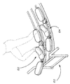
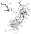
Turning now to FIGS. 10 and 11, there are shown a rear perspective view and a front perspective view of an
必要に応じて、また必要なときに、円筒形コネクタ102による単一のユニットと同様にハンドグリップ98、100を回転させることができ、そのため、「静止」時に実質的に水平な方向に延在し、異なる運動動作を行うときに使用者による「上下」移動が可能になり、そのため、例えば、使用者が上記で述べたのとは反対の方向に向くこともできる。
The
当然、本発明が前述の実施形態の詳細に制限されないことを理解されたい。 Of course, it should be understood that the invention is not limited to the details of the foregoing embodiments.
記載のように、各傾斜それぞれを上る支持プレートの上方向の動きに抵抗する任意の適切な手段を設けることができ、移動通路の範囲、および構成を画定する任意の適切な形態のトラック/支持機構を設けることができる。当然、様々な実施形態に関して示した様々な特徴を、必要に応じて任意の適切な形および組み合わせで組み合わせることができる。 As described, any suitable means can be provided that resists upward movement of the support plate up each slope, and any suitable form of track / support that defines the extent and configuration of the travel path. A mechanism can be provided. Of course, the various features shown for the various embodiments can be combined in any suitable form and combination as desired.
10 運動器具
12 支持部材、支持面
12A トラック
12B トラック
14 中心領域
16 端部領域
18 端部領域
20 安定脚部構成
22 安定脚部構成
24 支持プレート、フットプレート
26 支持プレート、フットプレート
30 端部領域
32 ウェート機構
34 端部領域
36 ウェート機構
38 ウェート要素
38B ウェート機構
38A ウェート機構
40 アーム
40A アーム
40B アーム
42 緩衝器
42A 緩衝器
42B 緩衝器
44 ウェート要素
44A ウェート機構
44B ウェート機構
46 アーム
46A アーム
46B アーム
48 緩衝器
48A 緩衝器
48B 緩衝器
50 フットプレート
52 フットプレート
54 支持機構
56 ウェート機構
58 ウェート機構
60 支持トラック
62 フットプレート
64 フットプレート
66 運動器具
68 管状トラック
70 管状トラック
72 フレーム床支持部
74 フレーム床支持部
76 ハンドルバー構成、ハンドグリップ機構、ハンドルバー延長部
78 ハンドグリップ、ハンドグリップ機構
80 ハンドグリップ、ハンドグリップ機構
82 支持プレート、フットプレート
84 支持プレート
86 ウェート
87 延長アーム
88 ウェート
89 延長アーム
90 運動器具
92 クレードル・フレーム
94 直立した支持部
96〜102 ハンド・レスト/ハンドルバー構成
98 ハンドグリップ
100 ハンドグリップ
102 円筒形コネクタ
A 矢印
B 矢印
DESCRIPTION OF
Claims (22)
Applications Claiming Priority (2)
| Application Number | Priority Date | Filing Date | Title |
|---|---|---|---|
| GBGB0912979.2A GB0912979D0 (en) | 2009-07-27 | 2009-07-27 | Exercise apparatus |
| GBGB0919328.5A GB0919328D0 (en) | 2009-07-27 | 2009-11-04 | Exercise apparatus |
Publications (2)
| Publication Number | Publication Date |
|---|---|
| JP2011025026A true JP2011025026A (en) | 2011-02-10 |
| JP2011025026A5 JP2011025026A5 (en) | 2013-08-01 |
Family
ID=41066841
Family Applications (1)
| Application Number | Title | Priority Date | Filing Date |
|---|---|---|---|
| JP2010155300A Pending JP2011025026A (en) | 2009-07-27 | 2010-07-07 | Exercise apparatus |
Country Status (8)
| Country | Link |
|---|---|
| US (1) | US20110021325A1 (en) |
| EP (1) | EP2281609A1 (en) |
| JP (1) | JP2011025026A (en) |
| CN (1) | CN101966381A (en) |
| AU (1) | AU2010202659A1 (en) |
| CA (1) | CA2709142A1 (en) |
| GB (2) | GB0912979D0 (en) |
| TW (1) | TW201114459A (en) |
Families Citing this family (10)
| Publication number | Priority date | Publication date | Assignee | Title |
|---|---|---|---|---|
| US9061191B2 (en) | 2010-01-11 | 2015-06-23 | Craig Sidley | Push-pass technique and system for training soccer players |
| US8702539B2 (en) * | 2010-01-11 | 2014-04-22 | Craig S. Sidley | Push-pass technique and system for training soccer players |
| CZ23050U1 (en) * | 2011-09-15 | 2011-12-12 | Kubická@Lucie | Strengthening machine |
| US20150031478A1 (en) * | 2013-07-23 | 2015-01-29 | Miles Alden-Dunn | Soccer Training Device |
| US9486668B2 (en) * | 2014-10-21 | 2016-11-08 | Ronald Williams | Weight stack pushup exercise device |
| GB201604565D0 (en) | 2016-03-17 | 2016-05-04 | Enanef Ltd | Exercise apparatus |
| US10493349B2 (en) | 2016-03-18 | 2019-12-03 | Icon Health & Fitness, Inc. | Display on exercise device |
| US10625137B2 (en) | 2016-03-18 | 2020-04-21 | Icon Health & Fitness, Inc. | Coordinated displays in an exercise device |
| US10625114B2 (en) | 2016-11-01 | 2020-04-21 | Icon Health & Fitness, Inc. | Elliptical and stationary bicycle apparatus including row functionality |
| USD989894S1 (en) * | 2022-11-08 | 2023-06-20 | Gavin Edward Hamer | Sliding exercise and measurement device |
Citations (7)
| Publication number | Priority date | Publication date | Assignee | Title |
|---|---|---|---|---|
| US3627315A (en) * | 1968-11-26 | 1971-12-14 | Walter Marcyan | Leg developing device |
| US3866914A (en) * | 1971-05-24 | 1975-02-18 | Boswell Bruce | Variable weight resistance football training device |
| US4619454A (en) * | 1985-05-30 | 1986-10-28 | Walton Ronald A | Leg conditioner for leg split type exercise |
| JPS6272662U (en) * | 1985-10-25 | 1987-05-09 | ||
| JPH07250918A (en) * | 1993-09-30 | 1995-10-03 | Gary D Piaget | Stride movement apparatus provided with orbit curved upward |
| JP2001309993A (en) * | 2000-04-28 | 2001-11-06 | Omron Corp | Exercise appliance |
| JP2006526456A (en) * | 2003-06-05 | 2006-11-24 | フレックシペド アクチスカベット | Physical exercise equipment and footrest platform for use with this equipment |
Family Cites Families (6)
| Publication number | Priority date | Publication date | Assignee | Title |
|---|---|---|---|---|
| US5217420A (en) * | 1990-01-18 | 1993-06-08 | Water Products Research Co. | Exercise apparatus for underwater use |
| US5064190A (en) * | 1990-02-23 | 1991-11-12 | Holt Peter P | Cross-country skiing and exercising machine |
| US5855538A (en) * | 1997-04-08 | 1999-01-05 | Argabright; John | Leg extension machine with upwardly curved tracks |
| US7658698B2 (en) * | 2006-08-02 | 2010-02-09 | Icon Ip, Inc. | Variable stride exercise device with ramp |
| GB0816453D0 (en) * | 2008-09-09 | 2008-10-15 | Enanef Ltd | Leg exerciser device |
| US7931568B1 (en) * | 2009-11-05 | 2011-04-26 | Asia Regent Limited | Ski exercising apparatus |
-
2009
- 2009-07-27 GB GBGB0912979.2A patent/GB0912979D0/en not_active Ceased
- 2009-11-04 GB GBGB0919328.5A patent/GB0919328D0/en not_active Ceased
-
2010
- 2010-06-18 EP EP10166577A patent/EP2281609A1/en not_active Withdrawn
- 2010-06-25 AU AU2010202659A patent/AU2010202659A1/en not_active Abandoned
- 2010-07-07 CA CA2709142A patent/CA2709142A1/en not_active Abandoned
- 2010-07-07 JP JP2010155300A patent/JP2011025026A/en active Pending
- 2010-07-19 TW TW099123619A patent/TW201114459A/en unknown
- 2010-07-26 US US12/843,709 patent/US20110021325A1/en not_active Abandoned
- 2010-07-27 CN CN2010102413481A patent/CN101966381A/en active Pending
Patent Citations (7)
| Publication number | Priority date | Publication date | Assignee | Title |
|---|---|---|---|---|
| US3627315A (en) * | 1968-11-26 | 1971-12-14 | Walter Marcyan | Leg developing device |
| US3866914A (en) * | 1971-05-24 | 1975-02-18 | Boswell Bruce | Variable weight resistance football training device |
| US4619454A (en) * | 1985-05-30 | 1986-10-28 | Walton Ronald A | Leg conditioner for leg split type exercise |
| JPS6272662U (en) * | 1985-10-25 | 1987-05-09 | ||
| JPH07250918A (en) * | 1993-09-30 | 1995-10-03 | Gary D Piaget | Stride movement apparatus provided with orbit curved upward |
| JP2001309993A (en) * | 2000-04-28 | 2001-11-06 | Omron Corp | Exercise appliance |
| JP2006526456A (en) * | 2003-06-05 | 2006-11-24 | フレックシペド アクチスカベット | Physical exercise equipment and footrest platform for use with this equipment |
Also Published As
| Publication number | Publication date |
|---|---|
| GB0919328D0 (en) | 2009-12-23 |
| US20110021325A1 (en) | 2011-01-27 |
| EP2281609A1 (en) | 2011-02-09 |
| TW201114459A (en) | 2011-05-01 |
| AU2010202659A1 (en) | 2011-02-10 |
| CN101966381A (en) | 2011-02-09 |
| CA2709142A1 (en) | 2011-01-27 |
| GB0912979D0 (en) | 2009-09-02 |
Similar Documents
| Publication | Publication Date | Title |
|---|---|---|
| JP2011025026A (en) | Exercise apparatus | |
| US10010747B2 (en) | Rowing exercise device and method of using same | |
| AU2015363271B9 (en) | Exercise apparatus | |
| US5531658A (en) | Exercise device for building and rehabilitating waist | |
| US5967944A (en) | Cross-training exercise apparatus | |
| US7476188B2 (en) | Torso exercise device | |
| US20160346599A1 (en) | Exercise Machine with Multiple Exercising Modes | |
| US20040097335A1 (en) | Exercise apparatus simulating skating motions | |
| US9339686B2 (en) | High knees exercise apparatus | |
| US7435207B2 (en) | Collapsible and storable apparatus for exercising core muscles | |
| US11213717B2 (en) | Power rowing machine with pivoting weight arm | |
| US20090318274A1 (en) | Balance trainer | |
| US9233277B1 (en) | Exercise bench methods and apparatus | |
| AU2015298560B2 (en) | Standup paddle board core activator | |
| JP5213086B1 (en) | Exercise assistance device | |
| CN212395733U (en) | Multi-functional physical training ware | |
| NZ728783B2 (en) | Standup paddle board core activator |
Legal Events
| Date | Code | Title | Description |
|---|---|---|---|
| A521 | Written amendment |
Free format text: JAPANESE INTERMEDIATE CODE: A523 Effective date: 20130618 |
|
| A621 | Written request for application examination |
Free format text: JAPANESE INTERMEDIATE CODE: A621 Effective date: 20130618 |
|
| A977 | Report on retrieval |
Free format text: JAPANESE INTERMEDIATE CODE: A971007 Effective date: 20140228 |
|
| A131 | Notification of reasons for refusal |
Free format text: JAPANESE INTERMEDIATE CODE: A131 Effective date: 20140318 |
|
| A02 | Decision of refusal |
Free format text: JAPANESE INTERMEDIATE CODE: A02 Effective date: 20140902 |