JP2011022019A - Object detection device - Google Patents
Object detection device Download PDFInfo
- Publication number
- JP2011022019A JP2011022019A JP2009167682A JP2009167682A JP2011022019A JP 2011022019 A JP2011022019 A JP 2011022019A JP 2009167682 A JP2009167682 A JP 2009167682A JP 2009167682 A JP2009167682 A JP 2009167682A JP 2011022019 A JP2011022019 A JP 2011022019A
- Authority
- JP
- Japan
- Prior art keywords
- scale
- light
- detection device
- lever portion
- lever
- Prior art date
- Legal status (The legal status is an assumption and is not a legal conclusion. Google has not performed a legal analysis and makes no representation as to the accuracy of the status listed.)
- Pending
Links
Images


Abstract
Description
この発明は、対象物の有無、大きさ又は移動量を検出する装置に関する。 The present invention relates to an apparatus for detecting the presence / absence, size, or movement amount of an object.
印刷機、スキャナ、自動改札機、自動販売機、ATMなどの機械においては、用紙、切符、紙幣などの取り扱い対象物の有無、大きさ又は移動量を供給または排出の過程で検出することが要請される。 For machines such as printing presses, scanners, automatic ticket gates, vending machines, ATMs, etc., it is required to detect the presence, size, or amount of movement of handling objects such as paper, tickets, and banknotes during the supply or discharge process. Is done.
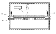
この種の検出装置として、用紙の供給路に対向して配置された上下のローラとLED及びPSDを備えたもの、並びにLED及びPSDに代えてレバーと、レバーの後端に取り付けられた反射板と、反射板に向かって発光するとともに反射光を受光するフォトセンサとを備えたものが知られている(特許文献1[従来技術]欄)。前者は、図11に示すように常時はバネ103によって上ローラ101が下ローラ102に近づく方向に付勢されており、用紙の通過時にバネ103の復元力に抗して用紙の厚み分だけ上ローラ101が下ローラ102から遠ざかり、上ローラ101の変位量をLEDとPSDとで光学的に検知するものである。後者は、図12に示すようにレバー104が支点に揺動可能に固定されていて、レバー104の先端が上ローラ101の軸に連結されており、常時はバネ103によってレバー104が上ローラ101を下ローラ102に近づける方向に付勢されており、用紙の通過に伴って揺動するレバー104後端の変位量をフォトセンサ105で検知するものである。
This type of detection device includes an upper and lower roller disposed facing a paper supply path, an LED and a PSD, a lever instead of the LED and PSD, and a reflector attached to the rear end of the lever. And a photosensor that emits light toward the reflector and receives the reflected light is known (Patent Document 1 [Prior Art] column). As shown in FIG. 11, the former is normally urged by the
また、これを改良し、図13に示すようにレバー104後端を複数の枝106に分岐させたり、レバー後端を扇形にして放射状のスリットを設けたりして、フォトインタラプタの光が通過する枝やスリットの数をもって検知するようにしたものも知られている(特許文献1[実施形態])。更にまた、前記上ローラの如く検出対象物の当接に伴って直接的に変位する要素や、前記レバーの如く間接的に変位する要素の変位量を測定する手段として公知のロータリーエンコーダ(特許文献2)を用いた装置も知られている(特許文献3及び4)。
Further, by improving this, as shown in FIG. 13, the rear end of the
しかし、特許文献1の[従来技術]欄に記載の第一番目の装置は、PSD自体が高価であるうえに、上ローラに反りが生じないように高い精度で加工する必要があることから、製造コストが著しく高い。第二番目の装置は、使用中にフォトセンサが汚れた場合に変位量を誤検知する可能性がある。
特許文献1の[実施形態]欄に記載の装置では、使用する紙厚が0.05〜0.3mm程度の範囲とすると、紙厚にて紙の種類を特定するには0.01mm以下の分解能を必要とするところ、0.01mm以下の幅のスリットや枝を形成することは困難である。また、特許文献3及び4に記載の装置では、平坦面と傾斜面とが透過性材料にて周方向に交互に形成されて位相格子をなす円盤状のスケールがエンコーダに用いられており、装置を小型化できないし、スケールの組み付け時にバラツキが生じる。
それ故、この発明の課題は、検出精度及び分解能に優れて小型化可能な検出装置を低コストで提供することにある。
However, since the first device described in the [Prior Art] column of
In the apparatus described in the [Embodiment] column of
Therefore, an object of the present invention is to provide a detection device that is excellent in detection accuracy and resolution and that can be miniaturized at low cost.
その課題を解決するために、この発明の検出装置は、
対象物の有無、大きさ又は移動量を検出する装置であって、
光透過性樹脂からなり、対象物と当接可能な接点を有し、対象物の当接に伴って前記接点が変位するレバー部と、
レバー部と同一材料にて一体成形され、レバー部の変位に応じて変位可能で、多数の遮光領域と透光領域とが変位方向に交互に形成されたスケール部と、
スケール部に光を照射する光源と、
スケール部を透過した光を受光する受光器と
を備えることを特徴とする。
In order to solve the problem, the detection device of the present invention is:
A device that detects the presence, size, or amount of movement of an object,
A lever portion made of a light-transmitting resin, having a contact that can come into contact with an object, and the contact being displaced with the contact of the object;
A scale part that is integrally formed of the same material as the lever part, can be displaced according to the displacement of the lever part, and in which a large number of light-shielding areas and translucent areas are alternately formed in the displacement direction;
A light source for irradiating the scale with light;
And a light receiver that receives light transmitted through the scale portion.
この発明の検出装置によれば、対象物がレバー部の接点に当接すると、レバー部が変位し、その変位に応じてスケール部が変位する。そして、スケール部を透過した光によって形成されるパルス列に基づいて変位量を検出する。PSDのような高価な部品は必要でない。スケール部は、遮光領域と透光領域とはプリズム加工、粗面処理、印刷などの手段で形成可能であるので、これらの領域を0.01mm以下の間隔で高精度に形成することができ、分解能に優れる。また、受光器は受光の有無だけを判定できればよいから、少々の曇りや汚れが存在しても誤検知することはない。そして、レバー部とスケール部とが一体成形されているので、レバー部とスケール部との間を中継する部材が無く小型であり、しかも組み付け時にレバー部とスケール部との相対位置が製造時から変動することがなく、組み付けに伴うバラツキが少ない。 According to the detection device of the present invention, when the object comes into contact with the contact of the lever portion, the lever portion is displaced, and the scale portion is displaced according to the displacement. Then, the displacement amount is detected based on the pulse train formed by the light transmitted through the scale portion. Expensive parts such as PSD are not required. Since the scale part can be formed by means such as prism processing, rough surface treatment, printing, etc., the light shielding region and the light transmitting region, these regions can be formed with high accuracy at intervals of 0.01 mm or less, Excellent resolution. Further, since the light receiver only needs to be able to determine the presence or absence of light reception, it will not be erroneously detected even if there is a little cloudiness or dirt. And since the lever part and the scale part are integrally molded, there is no member that relays between the lever part and the scale part, and it is compact, and the relative position between the lever part and the scale part when assembled is from the time of manufacture. There is no fluctuation, and there is little variation with assembly.
前記対象物の大きさとは、例えば対象物の厚み又は対象物表面の凹凸レベルである。
更に、前記レバー部及びスケール部を支持する回転軸を備え、前記レバー部及びスケール部は回転軸より互いに異なる径方向に延びているようにすることで、スケール部の変位量を接点のそれに比例させやすくして検出精度を向上させることができる。この構成において、前記レバー部及びスケール部が、互いに180°ではない角度をなす径方向に延びるようにすると、一層小型化できる。
The size of the object is, for example, the thickness of the object or the unevenness level of the object surface.
Furthermore, a rotation shaft for supporting the lever portion and the scale portion is provided, and the lever portion and the scale portion extend in different radial directions from the rotation shaft, so that the displacement amount of the scale portion is proportional to that of the contact point. It is possible to improve the detection accuracy. In this configuration, if the lever portion and the scale portion extend in a radial direction that forms an angle other than 180 °, the size can be further reduced.
前記回転軸を備える構成において、前記回転軸を回転可能に支持する軸受け部を有し、前記スケール部、光源及び受光器を収納する容器を更に備えると好ましい。レバー部とスケール部が一体成形されているので、容器も小型である。更に好ましくは、レバー部を対象物に圧接させる弾性体を備え、レバー部及びスケール部のいずれかが、前記容器と係り合って弾性体の復元力に抗してレバー部を所定の角度に決めるストッパーを一体的に有するものである。これにより、対象物が存在しないときはストッパーが容器と係り合うことにより、レバー部が基準となる角度に保たれ、対象物が存在するときはその大きさや移動量に応じて弾性体の復元力に抗してレバー部が変位するからである。 In the configuration including the rotating shaft, it is preferable that the rotating shaft further includes a bearing portion that rotatably supports the rotating shaft, and a container that houses the scale portion, the light source, and the light receiver. Since the lever part and the scale part are integrally formed, the container is also small. More preferably, an elastic body that presses the lever portion against the object is provided, and either the lever portion or the scale portion engages with the container and determines the lever portion at a predetermined angle against the restoring force of the elastic body. It has a stopper integrally. As a result, when the object is not present, the stopper is engaged with the container, so that the lever portion is kept at a reference angle, and when the object is present, the restoring force of the elastic body according to the size and the moving amount. This is because the lever portion is displaced against this.
尚、レバー部とスケール部とが異なる材料で成形される場合は、スケール部がレバー部と結合するように光透過性樹脂にて成形される。例えばレバー部を金属で形成し、その後、スケール部がレバー部と一体成形されてもよいし、両者を個別に成形した後、スケール部及びレバー部の一方が他方に圧入されてもよい。 When the lever portion and the scale portion are formed of different materials, the lever portion and the scale portion are formed of a light transmissive resin so that the scale portion is coupled to the lever portion. For example, the lever portion may be formed of metal, and then the scale portion may be integrally formed with the lever portion, or after both are individually formed, one of the scale portion and the lever portion may be press-fitted into the other.
検出精度及び分解能に優れて小型化可能な検出装置を低コストで提供できるので、大小様々な機械における供給・排出過程において、対象物を正確に検出することができる。 Since a detection device that is excellent in detection accuracy and resolution and can be miniaturized can be provided at a low cost, an object can be accurately detected in the supply / discharge process in various machines.
−実施形態1−
以下、この発明を実施形態に基づいて具体的に説明する。図1〜3は第一の実施形態の検出装置をそれぞれ別の方向から眺めた斜視図、図4は同検出装置の回転軸に平行な鉛直方向断面図、図5は同検出装置に適用されている内ホルダー、コネクター及び基板を示す斜視図、図6は同検出装置に適用されているスケール一体型レバーを示す正面図である。
Hereinafter, the present invention will be specifically described based on embodiments. 1 to 3 are perspective views of the detection device of the first embodiment viewed from different directions, FIG. 4 is a vertical sectional view parallel to the rotation axis of the detection device, and FIG. 5 is applied to the detection device. FIG. 6 is a front view showing a scale-integrated lever applied to the detection device.
検出装置1は、用紙の厚みを検出する装置であって、図1〜図4に示すように平面視で略十字形で上方に突出して主要部品収納空間が設けられた外ホルダー2、外ホルダー2の下面に固定された回路基板3、受光素子4、コリメートレンズ5、発光素子6及びスケール一体型レバー7を備える。
The
スケール一体型レバー7は、全体が光透過性樹脂からなり、図6に示すようにレバー部71、スケール部72、回転軸73及びストッパー74が回転軸73部分を除いて厚さ 1.3mm程度の板状に一体成形されたものである。スケール一体型レバー7の輪郭は、正面視で互いに直交する二辺a、b、これらの二辺のうち一辺aと平行で辺aよりも短い辺c、及び辺aと辺cとを結ぶ斜めの辺dとからなる略台形をなす。そして、辺aと辺dとが交差する角にほぼ辺dに沿って延びるようにレバー部71が形成され、辺bと辺cとが交差する角に辺cに沿って延びるようにストッパー74が形成されている。レバー部71の周面は、先端に向かうほどに辺dの延長線から離れて辺bに近づくように滑らかに曲がっており、検出対象となる用紙との接点を形成している。
The scale-integrated
回転軸73は、辺dの中間部に前記板状部分の両面に直交するように突出した円柱状をなしている。従って、レバー部71とストッパー74とは回転軸73を間にして互いにほぼ対角位置にある。また、辺aと辺bとが交差する角の付近には、回転軸73を中心とする周方向に等間隔に交互に配列した多数の遮光領域と透光領域とからなるスケール部72が形成されている。スケール部72を設ける手段としては、図7に図6のXX断面図として示すように、前記板状部分の一方の主面に形成された透光領域72aとしての水平の滑面と遮光領域72bとしての非水平の滑面とからなるプリズム(図7(a)及び(b))でもよいし、透光領域72aとしての水平の滑面の隣に遮光材料を印刷するか粗面処理をするかして遮光領域72b(図7(c))としてもよい。
The rotating
回転軸73は、外ホルダー2の上端にある軸受け部21にレバー部71が上でスケール部72が下になるように支持されている。回転軸73の外周面には回転軸73をレバー部71が上に付勢される方向に復元力が働くコイルバネ75が取り付けられている。そして、その復元力はストッパー74が外ホルダー2と係り合うことにより抑制されて、レバー部71の前記接点と回転軸73とを結ぶ線が水平に対してほぼ30度の傾きとなるように保たれている。スケール部72の両端の透光領域72aまたは遮光領域72bは、この線から100〜150度回転した位置にある。
The
回路基板3上には、図4及び図5に示すようにU字形の内ホルダー8とコネクタ31が取り付けられ、内ホルダー8の一方の側に受光素子4、他方の側にレンズ5及び発光素子6がそれぞれ収納されている。内ホルダー8を挟んでコネクタ31と反対側の回路基板3の端部には位置決め用のボス孔32が形成され、これに外ホルダー2のボス(図示省略)が嵌合することにより、スケール部72がレンズ5と対向するように外ホルダー2に対する内ホルダー8の位置が決められている。回路基板3の下面はカバー33で覆われている。
A U-shaped
検出装置1は、外ホルダー2の下面両側に形成された2つの位置決めボス22、22を印刷機械の位置決め用ボス孔に嵌合し、外ホルダー2におけるコネクタ31と反対側端部に形成されたねじ孔23と印刷機械のねじ孔に止めねじをねじ嵌合することによって、印刷機械に固定されて使用される。
The
図8は、検出装置1の使用時の動作を示す図である。用紙が存在せずレバー部71の最高位が基準面と接しているとき(図中、実線の位置)から、供給されてくる用紙Kに押されてレバー部71の最高位がΔt低下したとする(図中、破線の位置)。レバー部71の最高位から回転軸73の中心までの長さをL、そのときのレバー部71の水平に対する角度をそれぞれθ、回転軸73の中心からスケール部72の光軸中心までの長さをJ、レバー部71の変位に伴うスケール部72の微小変位量をΔdとする。レバー部71の最高位が常にできる限り基準面に対する一つの垂線V上に存在するように設計することにより、相似の関係から、L:Δt/cosθ=J:Δdとなり、Δt=Δd(1/J)Lcosθが導かれる。レバー部71の最高位から回転軸73の中心までの長さ及びレバー部71の水平に対する角度は、いずれも変数であるが、レバー部71の最高位の低下に伴うLの減少とともにcosθが増加するから、互いに相殺しあう。従って、(1/J)Lcosθはほぼ一定値を保つ。その結果、ΔtとΔdが比例する。
FIG. 8 is a diagram illustrating an operation when the
この検出装置1によれば、図略の供給ローラにて供給される用紙がレバー部71の接点に当接すると、レバー部71が変位し、その変位量にほぼ比例してスケール部72が変位する。そして、発光素子6から発せられてスケール部72の透光領域を透過した光が受光素子4で受光される。受光素子4の表面が少々曇ったり汚れたりしていても受光できれば支障ない。受光素子4は2ch内蔵されていて、透光領域72aと遮光領域72bのピッチを0.0423mmとすると、8逓倍することにより分解能が0.0053mmのパルス信号を出力する。そして、レバー部71とスケール部72とが一体成形されているので、レバー部71とスケール部72との間を中継する部材が無く小型であり、しかも組み付け時にレバー部71とスケール部72との相対位置が製造時から変動することがなく、組み付けに伴うバラツキが少ない。供給ローラは供給さえできれば足り、高精度に表面を仕上げる必要は無い。
According to this
−実施形態2−
第二の実施形態の検出装置では、図9に示すようにレバー部71とスケール部72との角度を180°より大きくすることにより、鉛直方向に移動する対象物の検出も可能とされている。この場合、スケール一体型レバー7を実施形態1のものと交換するだけでよい。
Embodiment 2
In the detection device of the second embodiment, as shown in FIG. 9, the object moving in the vertical direction can be detected by making the angle between the
−実施形態3−
第三の実施形態の検出装置は、図10に示すように対象物の移動方向をレバー部71の変位方向とほぼ一致させたもので、対象物の移動速度の検出に好適である。
As shown in FIG. 10, the detection device of the third embodiment has the moving direction of the object substantially coincident with the displacement direction of the
1 検出装置
2 外ホルダー
3 回路基板
4 受光素子
5 レンズ
6 発光素子
7 スケール一体型レバー
71 レバー部
72 スケール部
73 回転軸
74 ストッパー
75 コイルバネ
DESCRIPTION OF
Claims (14)
光透過性樹脂からなり、対象物と当接可能な接点を有し、対象物の当接に伴って前記接点が変位するレバー部と、
レバー部と同一材料にて一体成形され、レバー部の変位に応じて変位可能で、多数の遮光領域と透光領域とが変位方向に交互に形成されたスケール部と、
スケール部に光を照射する光源と、
スケール部を透過した光を受光する受光器と
を備えることを特徴とする検出装置。 A device that detects the presence, size, or amount of movement of an object,
A lever portion made of a light-transmitting resin, having a contact that can come into contact with an object, and the contact being displaced with the contact of the object;
A scale part that is integrally formed of the same material as the lever part, can be displaced according to the displacement of the lever part, and in which a large number of light-shielding areas and translucent areas are alternately formed in the displacement direction;
A light source for irradiating the scale with light;
A detection device comprising: a light receiver that receives light transmitted through the scale unit.
対象物と当接可能な接点を有し、対象物の当接に伴って前記接点が変位するレバー部と、
レバー部と結合するように光透過性樹脂にて成形され、レバー部の変位に応じて変位可能で、多数の遮光領域と透光領域とが変位方向に交互に形成されたスケール部と、
スケール部に光を照射する光源と、
スケール部を透過した光を受光する受光器と
を備えることを特徴とする検出装置。 A device that detects the presence, size, or amount of movement of an object,
A lever portion having a contact capable of abutting against an object, wherein the contact is displaced as the object abuts;
A scale portion formed of a light-transmitting resin so as to be coupled to the lever portion, displaceable in accordance with the displacement of the lever portion, and a plurality of light-shielding regions and light-transmitting regions formed alternately in the displacement direction;
A light source for irradiating the scale with light;
A detection device comprising: a light receiver that receives light transmitted through the scale unit.
Priority Applications (1)
| Application Number | Priority Date | Filing Date | Title |
|---|---|---|---|
| JP2009167682A JP2011022019A (en) | 2009-07-16 | 2009-07-16 | Object detection device |
Applications Claiming Priority (1)
| Application Number | Priority Date | Filing Date | Title |
|---|---|---|---|
| JP2009167682A JP2011022019A (en) | 2009-07-16 | 2009-07-16 | Object detection device |
Publications (1)
| Publication Number | Publication Date |
|---|---|
| JP2011022019A true JP2011022019A (en) | 2011-02-03 |
Family
ID=43632234
Family Applications (1)
| Application Number | Title | Priority Date | Filing Date |
|---|---|---|---|
| JP2009167682A Pending JP2011022019A (en) | 2009-07-16 | 2009-07-16 | Object detection device |
Country Status (1)
| Country | Link |
|---|---|
| JP (1) | JP2011022019A (en) |
Cited By (1)
| Publication number | Priority date | Publication date | Assignee | Title |
|---|---|---|---|---|
| JP2015205775A (en) * | 2014-04-10 | 2015-11-19 | 株式会社リコー | Sheet material discrimination device and image formation device |
Citations (10)
| Publication number | Priority date | Publication date | Assignee | Title |
|---|---|---|---|---|
| JPS5622911A (en) * | 1979-08-02 | 1981-03-04 | Matsushita Electric Ind Co Ltd | Detecting method for linear displacement of linear motion body |
| JPS61164110A (en) * | 1985-01-16 | 1986-07-24 | Nissan Motor Co Ltd | Rotational angle detecting device |
| JPS62218809A (en) * | 1986-02-07 | 1987-09-26 | ランク・テイラ−・ホブソン・リミテツド | Device for measuring surface profile of workpiece |
| JPH0432713A (en) * | 1990-05-29 | 1992-02-04 | Kubota Corp | Position detector |
| JPH06288703A (en) * | 1993-04-06 | 1994-10-18 | Nippon Steel Corp | Shaft center position detecting method for cylindrical article |
| JPH07151534A (en) * | 1993-11-30 | 1995-06-16 | Kofu Nippon Denki Kk | Paper sheet thickness detecting mechanism |
| JPH1190799A (en) * | 1997-09-11 | 1999-04-06 | Toyoda Mach Works Ltd | Machine tool for crank pin machining and machining method for crank pin |
| JP2001227989A (en) * | 2000-02-17 | 2001-08-24 | Seiko Epson Corp | Optical scale |
| JP2003294401A (en) * | 2002-03-29 | 2003-10-15 | Canon Inc | Displacement detector and image forming apparatus |
| JP2007178235A (en) * | 2005-12-27 | 2007-07-12 | Kodenshi Corp | Rotary encoder for motor and its manufacturing method |
-
2009
- 2009-07-16 JP JP2009167682A patent/JP2011022019A/en active Pending
Patent Citations (10)
| Publication number | Priority date | Publication date | Assignee | Title |
|---|---|---|---|---|
| JPS5622911A (en) * | 1979-08-02 | 1981-03-04 | Matsushita Electric Ind Co Ltd | Detecting method for linear displacement of linear motion body |
| JPS61164110A (en) * | 1985-01-16 | 1986-07-24 | Nissan Motor Co Ltd | Rotational angle detecting device |
| JPS62218809A (en) * | 1986-02-07 | 1987-09-26 | ランク・テイラ−・ホブソン・リミテツド | Device for measuring surface profile of workpiece |
| JPH0432713A (en) * | 1990-05-29 | 1992-02-04 | Kubota Corp | Position detector |
| JPH06288703A (en) * | 1993-04-06 | 1994-10-18 | Nippon Steel Corp | Shaft center position detecting method for cylindrical article |
| JPH07151534A (en) * | 1993-11-30 | 1995-06-16 | Kofu Nippon Denki Kk | Paper sheet thickness detecting mechanism |
| JPH1190799A (en) * | 1997-09-11 | 1999-04-06 | Toyoda Mach Works Ltd | Machine tool for crank pin machining and machining method for crank pin |
| JP2001227989A (en) * | 2000-02-17 | 2001-08-24 | Seiko Epson Corp | Optical scale |
| JP2003294401A (en) * | 2002-03-29 | 2003-10-15 | Canon Inc | Displacement detector and image forming apparatus |
| JP2007178235A (en) * | 2005-12-27 | 2007-07-12 | Kodenshi Corp | Rotary encoder for motor and its manufacturing method |
Cited By (1)
| Publication number | Priority date | Publication date | Assignee | Title |
|---|---|---|---|---|
| JP2015205775A (en) * | 2014-04-10 | 2015-11-19 | 株式会社リコー | Sheet material discrimination device and image formation device |
Similar Documents
| Publication | Publication Date | Title |
|---|---|---|
| JP5192717B2 (en) | Flat top reflective optical encoder | |
| US9429513B2 (en) | Sensor apparatus and image forming apparatus incorporating same | |
| JP5072337B2 (en) | Optical displacement sensor and adjustment method thereof | |
| JP4785044B2 (en) | Reflective optical sensor and method for detecting surface roughness of measurement surface | |
| JP2007155467A (en) | Light beam scanner | |
| US10094684B2 (en) | Method of manufacturing rotary scale, rotary scale, rotary encoder, driving apparatus, image pickup apparatus and robot apparatus | |
| US11627229B2 (en) | Original reading apparatus | |
| JP6420846B2 (en) | Optical rotary encoder | |
| JP3725843B2 (en) | Reflective sensor | |
| KR100633817B1 (en) | Liquid accommodation container | |
| JP4793786B2 (en) | pointing device | |
| JP6571733B2 (en) | Angle measuring device for specifying rotation angle | |
| JP2011022019A (en) | Object detection device | |
| JP5108330B2 (en) | pointing device | |
| JP4057293B2 (en) | Document presence / absence detection sensor and document size detection sensor | |
| JP3723006B2 (en) | End face detection device | |
| US20050200599A1 (en) | Optical pointing device | |
| JP4515199B2 (en) | Translucent member used in optical sensor device | |
| JP2911762B2 (en) | Paper edge detection device | |
| US20030230703A1 (en) | Optical object discriminating apparatus, processing system and transport processing system | |
| JP3998644B2 (en) | Position detection device | |
| JP7330917B2 (en) | Optical scanning device and image forming device | |
| JP2007071781A (en) | Reflection type photosensor, travel object speed detector, and imaging forming device | |
| JP2000065950A (en) | Photosensor unit | |
| EP3492882B1 (en) | Liquid level detection sensor and specimen testing apparatus |
Legal Events
| Date | Code | Title | Description |
|---|---|---|---|
| A621 | Written request for application examination |
Free format text: JAPANESE INTERMEDIATE CODE: A621 Effective date: 20120713 |
|
| A977 | Report on retrieval |
Free format text: JAPANESE INTERMEDIATE CODE: A971007 Effective date: 20130412 |
|
| A131 | Notification of reasons for refusal |
Free format text: JAPANESE INTERMEDIATE CODE: A131 Effective date: 20130507 |
|
| A521 | Written amendment |
Free format text: JAPANESE INTERMEDIATE CODE: A523 Effective date: 20130611 |
|
| A131 | Notification of reasons for refusal |
Free format text: JAPANESE INTERMEDIATE CODE: A131 Effective date: 20140128 |
|
| A02 | Decision of refusal |
Free format text: JAPANESE INTERMEDIATE CODE: A02 Effective date: 20140603 |