JP2011007985A - Digital camera body and digital camera - Google Patents
Digital camera body and digital camera Download PDFInfo
- Publication number
- JP2011007985A JP2011007985A JP2009150680A JP2009150680A JP2011007985A JP 2011007985 A JP2011007985 A JP 2011007985A JP 2009150680 A JP2009150680 A JP 2009150680A JP 2009150680 A JP2009150680 A JP 2009150680A JP 2011007985 A JP2011007985 A JP 2011007985A
- Authority
- JP
- Japan
- Prior art keywords
- digital camera
- image
- imaging unit
- optical member
- focus
- Prior art date
- Legal status (The legal status is an assumption and is not a legal conclusion. Google has not performed a legal analysis and makes no representation as to the accuracy of the status listed.)
- Pending
Links
Images


Landscapes
- Focusing (AREA)
- Automatic Focus Adjustment (AREA)
- Studio Devices (AREA)
Abstract
Description
本発明は、動画撮影機能を有するデジタルカメラ本体およびデジタルカメラに関する。 The present invention relates to a digital camera body having a moving image shooting function and a digital camera.
従来、デジタルカメラのAF動作は、AFモジュールによる測距情報に基づいて撮影レンズを移動して合焦させている。 Conventionally, in an AF operation of a digital camera, a photographing lens is moved and focused based on distance measurement information by an AF module.
また、撮像素子を光軸に沿って移動させてAF動作を行う合焦方法が提案されている(例えば、特許文献1参照)。 Further, a focusing method for performing an AF operation by moving the image sensor along the optical axis has been proposed (for example, see Patent Document 1).
しかし、動画撮影時に撮影レンズを移動してAF動作を行うと、レンズ駆動音も録音されてしまう。そのため、雑音防止対策として、レンズ駆動機構を静音構造にする必要がある。ところが、既にユーザが所有している交換式レンズの場合、駆動機構がレンズ内に組み込まれているため、静音化が困難である。 However, if the AF operation is performed by moving the taking lens during moving image shooting, the lens driving sound is also recorded. Therefore, it is necessary to make the lens driving mechanism a silent structure as a noise prevention measure. However, in the case of an interchangeable lens already owned by the user, it is difficult to reduce the noise because the drive mechanism is incorporated in the lens.
また、特許文献1のように撮像素子を移動してAF動作を行う場合は、レンズ位置が不確定なため、コントラスト検出に必要な撮像素子の移動量が大きくなってしまう。 Further, when the AF operation is performed by moving the image sensor as in Patent Document 1, the lens position is indeterminate, and the amount of movement of the image sensor necessary for contrast detection becomes large.
本発明の課題は、動画撮影時に雑音の少ない動画撮影を実行することのできるデジタルカメラ本体およびデジタルカメラを提供することである。 An object of the present invention is to provide a digital camera body and a digital camera that can perform moving image shooting with less noise during moving image shooting.
本発明は、以下のような解決手段により前記課題を解決する。なお、理解を容易にするために、本発明の実施形態に対応する符号を付して説明するが、これに限定されるものではない。
請求項1に記載の発明は、光学部材(31)により形成される被写体像を動画撮影可能な撮像部(15)と、前記被写体像を前記撮像部(15)に合焦させるため、前記光学部材(31)の光軸に沿って前記撮像部(15)を移動させる駆動部材(17)と、所定位置に保持された前記光学部材(31)に対して、前記駆動部材(17)により前記撮像部(15)を移動して合焦させる制御手段(40)とを備えたことを特徴とするデジタルカメラ本体である。
請求項2に記載の発明は、請求項1に記載のデジタルカメラ本体であって、動画撮影時に録音するマイク(26)を備えたことを特徴とするデジタルカメラ本体である。
請求項3に記載の発明は、請求項1又は2に記載のデジタルカメラ本体であって、前記撮像部(15)は、静止画撮影または動画撮影を切り換えて実行可能であることを特徴とするデジタルカメラ本体である。
請求項4に記載の発明は、請求項1〜3のいずれか1項に記載のデジタルカメラ本体であって、前記制御手段(40)は、無限遠合焦位置に保持された前記光学部材(31)に対して、前記撮像部(15)を、前記光学部材(31)が無限遠合焦位置にあるとき被写体像が結像する像面位置を前端として移動させることを特徴とするデジタルカメラ本体である。
請求項5に記載の発明は、光学部材(31)と、前記光学部材(31)により形成される被写体像を動画撮影可能な撮像部(15)と、前記被写体像を前記撮像部(15)に合焦させるため、前記光学部材(31)の光軸に沿って前記撮像部(15)を移動させる駆動部材(17)と、所定位置に保持された前記光学部材(31)に対して、前記駆動部材(17)により前記撮像部(15)を移動して合焦させる制御手段(40)とを備えたことを特徴とするデジタルカメラである。
請求項6に記載の発明は、請求項5に記載のデジタルカメラであって、動画撮影時に録音するマイク(26)を備えたことを特徴とするデジタルカメラである。
請求項7に記載の発明は、請求項5又は6に記載のデジタルカメラであって、前記撮像部(15)は、静止画撮影または動画撮影を切り換えて実行可能であることを特徴とするデジタルカメラである。
請求項8に記載の発明は、請求項5〜7のいずれか1項に記載のデジタルカメラであって、前記制御手段(40)は、動画撮影時に、無限遠合焦位置に保持された前記光学部材(31)に対して、前記撮像部(15)を、前記光学部材(31)が無限遠合焦位置にあるとき被写体像が結像する像面位置を前端として移動させることを特徴とするデジタルカメラである。
請求項9に記載の発明は、請求項7に記載のデジタルカメラであって、前記制御手段(40)は、静止画撮影時に、所定位置に保持された前記撮像部(15)に対して、前記光学部材(31)を移動させて合焦させることを特徴とするデジタルカメラである。
請求項10に記載の発明は、請求項9に記載のデジタルカメラであって、前記制御手段(40)は、像面位置に保持された前記撮像部(15)に対して、前記光学部材(31)を、前記撮像部(15)が像面位置にあるとき無限遠の被写体像が結像する無限遠合焦位置を後端として移動させることを特徴とするデジタルカメラである。
請求項11に記載の発明は、請求項7に記載のデジタルカメラであって、前記制御手段(40)は、動画撮影時には、無限遠合焦位置に保持された前記光学部材(31)に対して、前記駆動部材(17)により前記撮像部(15)を、前記光学部材(31)が無限遠合焦位置にあるとき被写体像が結像する像面位置を前端として移動させて合焦させ、また、静止画撮影時には、前記像面位置に保持された前記撮像部(15)に対して、前記光学部材(31)を、前記撮像部(15)が像面位置にあるとき無限遠の被写体像が結像する前記無限遠合焦位置を後端として移動させて合焦させることを特徴とするデジタルカメラである。
The present invention solves the above problems by the following means. In addition, in order to make an understanding easy, although the code | symbol corresponding to embodiment of this invention is attached | subjected and demonstrated, it is not limited to this.
According to the first aspect of the present invention, an imaging unit (15) capable of capturing a moving subject image formed by the optical member (31) and the optical unit for focusing the subject image on the imaging unit (15). The drive member (17) moves the imaging unit (15) along the optical axis of the member (31) and the optical member (31) held at a predetermined position by the drive member (17). A digital camera body comprising a control means (40) for moving and focusing the image pickup section (15).
According to a second aspect of the present invention, there is provided the digital camera body according to the first aspect, further comprising a microphone (26) for recording during moving image shooting.
A third aspect of the present invention is the digital camera main body according to the first or second aspect, wherein the imaging unit (15) can switch and execute still image shooting or moving image shooting. It is a digital camera body.
Invention of Claim 4 is a digital camera main body of any one of Claims 1-3, Comprising: The said control means (40) is the said optical member (Holded at an infinite focus position). 31) The digital camera, wherein the image pickup unit (15) is moved with the image plane position on which the subject image is formed as the front end when the optical member (31) is at the infinite focus position. It is the main body.
The invention according to
A sixth aspect of the present invention is the digital camera according to the fifth aspect, further comprising a microphone (26) for recording during moving image shooting.
A seventh aspect of the present invention is the digital camera according to the fifth or sixth aspect, wherein the imaging unit (15) can execute switching between still image shooting and moving image shooting. It is a camera.
Invention of Claim 8 is a digital camera of any one of Claims 5-7, Comprising: The said control means (40) is hold | maintained at the infinity in-focus position at the time of video recording. The imaging unit (15) is moved relative to the optical member (31) with the image plane position where the subject image is formed as the front end when the optical member (31) is at an infinite focus position. It is a digital camera.
A ninth aspect of the present invention is the digital camera according to the seventh aspect, wherein the control means (40) is arranged for the imaging unit (15) held at a predetermined position during still image shooting. The digital camera is characterized in that the optical member (31) is moved and focused.
A tenth aspect of the present invention is the digital camera according to the ninth aspect, wherein the control means (40) is arranged such that the optical member (15) is located with respect to the imaging unit (15) held at an image plane position. 31) is a digital camera characterized in that when the imaging unit (15) is at the image plane position, the infinite focus position where an infinite subject image is formed is moved as a rear end.
The invention according to
本発明によれば、動画撮影時に雑音の少ない動画撮影を実行することのできるデジタルカメラ本体およびデジタルカメラを提供することができる。 ADVANTAGE OF THE INVENTION According to this invention, the digital camera main body and digital camera which can perform video recording with few noises at the time of video recording can be provided.
以下、図面を参照して、本発明の実施形態について説明する。なお、以下に示す各図には、説明と理解を容易にするために、xyz直交座標系を設けた。この座標系では、撮影者が光軸Aを水平として横長の画像を撮影する場合のカメラの位置(以下、通常の撮影位置という)において撮影者から見て左側に向かう方向をxプラス方向とする。また、通常の撮影位置において上側に向かう方向をyプラス方向とする。さらに、通常の撮影位置において被写体に向かう方向をzプラス方向とする。 Embodiments of the present invention will be described below with reference to the drawings. Each figure shown below is provided with an xyz orthogonal coordinate system for easy explanation and understanding. In this coordinate system, the direction toward the left as viewed from the photographer at the position of the camera when the photographer shoots a horizontally long image with the optical axis A horizontal (hereinafter referred to as a normal photographing position) is the x plus direction. . Also, the direction toward the upper side at the normal photographing position is the y plus direction. Furthermore, the direction toward the subject at the normal shooting position is the z plus direction.
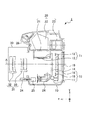
図1、図2は、本発明によるデジタルカメラの第1実施形態を示す概略的構成図であり、図1は静止画撮影時、図2は動画撮影時の状態である。 1 and 2 are schematic configuration diagrams showing a first embodiment of a digital camera according to the present invention. FIG. 1 shows a state during still image shooting, and FIG. 2 shows a state during moving image shooting.
このデジタルカメラ1はデジタル一眼レフカメラであり、カメラ本体(カメラボディ)10と、カメラ本体10に着脱自在に装着されるレンズ鏡筒30とを備えている。
The digital camera 1 is a digital single-lens reflex camera, and includes a camera body (camera body) 10 and a
カメラ本体10は、ミラー部11、シャッター14、撮像部15、モニタ19、ファインダ部20、AFモジュール24、AFモータ25、マイク26を備えている。
The
ミラー部11は、第1ミラー12、第2ミラー13を備え、図1に示すミラーダウン状態と、図2に示すミラーアップ状態とが切り換えられるものである。ミラーダウン状態にあるとき、第1ミラー12は、後述する撮影レンズ31の後部から出射される被写体光を、ファインダ部20へ反射させる反射ミラーである。第2ミラー13は、第1ミラー12の反射面の一部に設けられた半透過ミラーを透過した被写体光を、AFモジュール24へ反射させる反射ミラーである。
The
シャッター14は、図示しない複数のシャッタ羽根群を備え、後述するレリーズスイッチ48等による撮影指示に応じて、ミラー部11が図2に示すミラーアップ状態に跳ね上げられるのと同期してシャッタ羽根群を開閉させ、撮像部15に被写体光を入射する。
The
撮像部15は、撮像素子16、アクチュエータ17、撮像素子規制部材18を備えている。撮像素子16は、CCD、CMOS等の固体撮像素子であり、入射した被写体光を電気的な画像信号に変換して、後述する画像処理部42,43,44へ出力する。アクチュエータ17は、例えば超音波モータ等の駆動部材であり、撮像素子16を支持して光軸A方向(z方向)に沿って移動させる。撮像素子規制部材18は、アクチュエータ17が移動させる撮像素子16の移動方向前端(z方向前端)を規制する。
The
モニタ(画像表示部)19は、カメラ本体10の後部に設けられ、撮像部15で撮影した被写体像や、操作に関連した情報等を表示する液晶ディスプレイである。
The monitor (image display unit) 19 is a liquid crystal display that is provided at the rear of the
ファインダ部20は、ファインダスクリーン21、ペンタプリズム22、アイピース23を備えている。ファインダスクリーン21は、ミラー部11がミラーダウン状態にあるとき、第1ミラー12から反射される被写体光を入射して結像するためのスクリーンである。ペンタプリズム22は、ファインダスクリーン21によって結像された被写体光をアイピース23へと出射する多角形のプリズムである。アイピース23は、ペンタプリズム42から出射された被写体光が入射する位置に配置された接眼光学系である。
The
AFモジュール24は、ミラー部11がミラーダウン状態にあるとき、第2ミラー13から反射される被写体光を入射して、被写体とデジタルカメラ1との焦点を合わせるための演算処理を行い、その結果に応じてAFモータ25用の駆動信号を出力するものである。
When the
一方、レンズ鏡筒30は、撮影レンズ(光学部材)31、合焦レンズ駆動機構34を備えている。撮影レンズ31は、固定レンズ32、合焦レンズ33を備えている。固定レンズ32は、レンズ鏡筒30のフレームに固定されたレンズ群であり、合焦レンズ33は、レンズ鏡筒30のフレームに対して光軸A方向に沿って移動可能に取り付けられたレンズ群である。
On the other hand, the
合焦レンズ駆動機構34は、レンズ鏡筒30がカメラ本体10に装着されたとき、AFモータ25と駆動連結される。そして、AFモジュール24の出力信号に基づいてAFモータ25が駆動することで、合焦レンズ駆動機構34が合焦レンズ33を光軸A方向(z方向)に沿って移動させる。
The focusing
図3は、静止画撮影時の撮影レンズ31と撮像素子16との位置関係を示す。
FIG. 3 shows the positional relationship between the photographing
撮像素子16の位置は、図3(a)、(b)が像面位置(通常のデジタルカメラにおける撮像素子の位置)、図3(c)、(d)がそれより後方位置である。また、撮影レンズ31の位置は、図3(a)、(c)、(d)が無限遠合焦位置(被写体位置が無限遠の場合に合焦する位置)、図3(b)がそれより前方位置である。
As for the position of the
図3(a)、(b)が、通常のデジタルカメラにおいて被写体位置がそれぞれ無限遠、近距離の場合の撮影レンズと撮像素子との位置関係であり、本実施形態でも、静止画撮影時には、撮影レンズ31と撮像素子16との位置関係を図3(a)、(b)に示すように設定する。
FIGS. 3A and 3B show the positional relationship between the photographing lens and the image sensor when the subject position is infinity and short distance in a normal digital camera. The positional relationship between the
すなわち、図3(a)に示すように、撮像素子16が所定位置(像面位置)、被写体位置が無限の場合は、撮影レンズ31の移動により合焦可能である。また、図3(b)に示すように、撮像素子16が所定位置(像面位置)、被写体位置が近距離の場合は、撮影レンズ31の移動により合焦可能である。
That is, as shown in FIG. 3A, when the
これに対し、図3(c)に示すように、撮像素子16が所定の像面位置と異なり、被写体位置が無限の場合は、撮影レンズ31を無限位置に移動しても合焦不可能である。また、図3(d)に示すように、撮像素子16が所定の像面位置と異なり、被写体位置が近距離の場合は、撮影レンズ31の移動により合焦可能である。
On the other hand, as shown in FIG. 3C, when the
一般に、撮影レンズと撮像素子とは所定の相互間位置となるように設計されているため、例えば図3(c)に示すように、撮像素子が所定の像面位置とは異なる位置に配置されると、合焦のために設計された撮影レンズの設計移動範囲から外れてしまい、撮影レンズの移動では合焦が不可能になる場合がある。つまり、撮影レンズ31の設計範囲どおりの移動で撮像素子16に合焦させるためには、撮像素子16は所定位置(像面位置)に保持される必要がある。
In general, since the photographic lens and the image sensor are designed to have a predetermined mutual position, for example, as shown in FIG. 3C, the image sensor is arranged at a position different from the predetermined image plane position. In this case, the photographic lens designed for focusing may be out of the design movement range, and the photographic lens may not be able to focus when the photographic lens is moved. That is, in order to focus on the
図4は、動画撮影時の撮影レンズ31と撮像素子16との位置関係を示す。
FIG. 4 shows the positional relationship between the photographing
撮像素子16の位置は、図4(a)が像面位置(通常のデジタルカメラにおける撮像素子の位置)、図4(b)がそれより後方位置、図4(c)が像面位置より前方位置である。また、撮影レンズ31の位置は、図4(a)、(b)が無限遠合焦位置(被写体位置が無限遠の場合に合焦する位置)、図4(c)がそれより前方位置である。
As for the position of the
本実施形態では、動画撮影時には、撮影レンズ31と撮像素子16との位置関係を図4(a)、(b)に示すように設定する。
In this embodiment, at the time of moving image shooting, the positional relationship between the shooting
すなわち、図4(a)に示すように、撮影レンズ31が所定の位置(無限遠合焦位置)、被写体位置が無限の場合は、撮像素子16が所定の像面位置に位置することで合焦可能である。また、図4(b)に示すように、撮影レンズ31が所定の位置(無限遠合焦位置)、被写体位置が近距離の場合は、撮像素子16が像面位置(通常のデジタルカメラにおける撮像素子の位置)から後方へ移動することで合焦可能である。
That is, as shown in FIG. 4A, when the photographing
これに対し、図4(c)に示すように、撮影レンズ31の位置が不確定であると、被写体位置が無限の場合、撮像素子16を像面位置から前方へ移動することで合焦可能ではあるが、撮像素子16の移動範囲が拡大してしまう。
On the other hand, as shown in FIG. 4C, when the position of the photographing
このように、撮影レンズの位置が不確定な場合、コントラストAFを行うには撮像素子を広範囲で移動させる必要がある。これにより合焦するまでの時間が長くなる。また、撮像素子を広範囲で移動させるスペースを確保するため、カメラのサイズが大きくなってしまう。 As described above, when the position of the photographing lens is indeterminate, it is necessary to move the image sensor over a wide range in order to perform contrast AF. As a result, the time until focusing is increased. In addition, the camera size is increased in order to secure a space for moving the image pickup device over a wide range.
図5に示すように、カメラ本体10は、デジタルカメラ1全体の動作を制御する制御手段(カメラ制御部)40を備え、カメラ制御部40はCPUで構成されている。カメラ制御部(カメラCPU)40には、撮像素子駆動回路41、ASIC(画像処理回路)44が接続されている。
As shown in FIG. 5, the
撮像素子駆動回路41は、カメラCPU40からの信号により撮像素子16を駆動させ、これにより、撮像素子16は、撮影像に基づいて光電変換信号を出力する。撮像素子16の出力信号が入力されるAFE(Analog Front End)回路42は、撮像素子16の出力信号に対してアナログ処理をする。AFE回路42の出力信号が入力されるA/Dコンバータ43は、撮影アナログ信号をデジタル信号に変換する。A/Dコンバータ43の出力信号が入力されるASIC44は、入力信号に対して所定の画像処理を行う。
The image
また、カメラCPU40には、画像表示回路45、動画モードスイッチ46、AFスイッチ47、レリーズ/動画スイッチ48が接続されている。
The
ASIC44で画像処理された撮影・ライブビュー画像は、画像表示回路45を経て、LCD等のモニタ19により表示される。動画モードスイッチ46は、静止画/動画撮影の切り換えをするスイッチである。AFスイッチ47は、これをオンするとAFモジュール24が測光・測距を行うスイッチである。レリーズ/動画スイッチ48は、これをオンすると静止画撮影を行うスイッチである。動画モードに設定されているときは、動画撮影を開始する。
The photographed / live view image processed by the
さらに、カメラCPU40には、AF回路51、AFレンズ駆動回路52、ミラー駆動回路53、シャッター駆動回路54、アクチュエータ駆動回路55が接続されている。
Further, an AF circuit 51, an AF
AF回路51は、AFモジュール24からの信号により位相差AFを行う。AFレンズ駆動回路52は、位相差AFによる情報で合焦レンズ(AFレンズ)33を合焦位置に移動させる。動画モードでは合焦レンズ33を所定位置に移動させる。ミラー駆動回路53は、第1ミラー12、第2ミラー13を図1に示すミラーダウン状態または、図2に示すミラーアップ状態に切り換える。シャッター駆動回路54は、シャッター14の開閉を制御する。アクチュエータ駆動回路55は、撮像素子16を移動させるアクチュエータ17を制御する。
The AF circuit 51 performs phase difference AF based on a signal from the
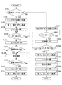
図6は、カメラCPU40の動作を示すフローチャートである。まず、動画撮影モードについて説明する。
FIG. 6 is a flowchart showing the operation of the
ステップS101において、動画撮影モードスイッチ46がオンされるか否かを判定する。 In step S101, it is determined whether or not the moving image shooting mode switch 46 is turned on.
動画撮影モードスイッチ46がオンされた場合(ステップS101のYES)、ステップS102において、合焦レンズ33が所定位置すなわち無限遠合焦位置に移動する。すなわち、AFモータ25が回転することで、合焦レンズ駆動機構34により合焦レンズ33を無限遠合焦位置に移動させる。合焦レンズ33が無限遠合焦位置にある状態を図2に示す。
When the moving image shooting mode switch 46 is turned on (YES in step S101), in step S102, the focusing
ステップS103において、第1ミラー12、第2ミラー13が撮影光学系から退避する。ミラー部11(第1ミラー12、第2ミラー13)が撮影光学系から退避した位置にある状態(ミラーアップ状態)を図2に示す。
In step S103, the
ステップS104において、シャッター14が開いて撮像素子16が露出する。この状態(シャッター14が開き撮像素子16が露出した状態)は、後述するステップS110において、シャッター14が閉まるまで継続する。
In step S104, the
ステップS105において、AFスイッチ47がオンされるか否かを判定することで、AFスイッチ47がオンされるまで待つ。 In step S105, it is determined whether or not the AF switch 47 is turned on to wait until the AF switch 47 is turned on.
AFスイッチ47がオンされると(ステップS105のYES)、ステップS106において、撮像素子16が移動してコントラストAFにより合焦する。すなわち、アクチュエータ17が駆動して、合焦レンズ33が無限遠合焦位置にある撮影レンズ31を通った被写体像が撮像素子16に合焦するように、撮像素子16を移動させる。アクチュエータ17として例えば超音波モータを用いることで、AF用駆動音(撮像素子16を移動させるための駆動音)を減少させた動画撮影が可能になる。
When the AF switch 47 is turned on (YES in step S105), in step S106, the
ステップS107において、動画スイッチ48がオンされるか否かを判定する。動画スイッチ48がオンされなければ(ステップS107のNO)、ステップS105に戻って、再びAFスイッチ47がオンされるのを待つ。 In step S107, it is determined whether or not the moving image switch 48 is turned on. If the moving image switch 48 is not turned on (NO in step S107), the process returns to step S105 to wait for the AF switch 47 to be turned on again.
動画スイッチ48がオンされると(ステップS107のYES)、ステップS108において、動画撮影を開始する。すなわち、撮像素子16により動画を撮影するとともに、マイク26により録音も行う。
When the moving image switch 48 is turned on (YES in step S107), moving image shooting is started in step S108. That is, a moving image is taken by the
ステップS109において、動画スイッチ48がオフされるか否かを判定する。動画スイッチ48がオフされなければ(ステップS109のNO)、オフされるまで動画撮影を続ける。 In step S109, it is determined whether or not the moving image switch 48 is turned off. If the moving image switch 48 is not turned off (NO in step S109), moving image shooting is continued until the moving image switch 48 is turned off.
動画スイッチ48がオフされると(ステップS109のYES)、ステップS110において、シャッター14が閉まり、動画撮影を終了する。すなわち、撮像素子16による動画の撮影を終了するとともに、マイク26による録音も終了する。
When the moving image switch 48 is turned off (YES in step S109), the
ステップS111において、第1ミラー12、第2ミラー13が復帰する。ミラー部11(第1ミラー12、第2ミラー13)が撮影光学系に復帰した位置にある状態(ミラーダウン状態)を図1に示す。
In step S111, the
つぎに、静止画撮影モードについて説明する。 Next, the still image shooting mode will be described.
ステップS101において、動画撮影モードスイッチ46がオフされた場合(ステップS101のNO)、ステップS201において、撮像素子16を所定位置(通常カメラの像面位置)に移動する。すなわち、アクチュエータ17の駆動により、撮像素子16を所定の像面位置(通常のデジタルカメラにおける撮像素子の位置)に移動させる。撮像素子16は、撮像素子規制部材18によってそれ以上は移動できず、これにより像面位置に保持される。
If the moving image shooting mode switch 46 is turned off in step S101 (NO in step S101), the
ステップS202において、AFスイッチ47がオンされるか否かを判定することで、AFスイッチ47がオンされるまで待つ。 In step S202, it is determined whether or not the AF switch 47 is turned on to wait until the AF switch 47 is turned on.
AFスイッチ47がオンされると(ステップS202のYES)、ステップS203において、位相差AFにより合焦する。すなわち、撮影レンズ31からの撮影光束は、ハーフミラーである第1ミラー12により反射される光学ファインダー光束と、第1ミラー12を透過し第2ミラー13により反射される焦点検出光束とに分割される。
When the AF switch 47 is turned on (YES in step S202), focusing is performed by phase difference AF in step S203. That is, the photographing light beam from the photographing
光学ファインダー光束は、ファインダ部20のファインダスクリーン21、ペンタプリズム22、アイピース23を順次透過する。これにより、撮影者は被写体を目で見て確認することができる。
The optical finder light flux sequentially passes through the
一方、焦点検出光束は、AFモジュール24に導かれて、位相差AFによる測距値が演算される。この測距値に基づいてAFモータ25が回転し、合焦レンズ駆動機構34により合焦レンズ33を移動させて合焦する。
On the other hand, the focus detection light beam is guided to the
ステップS204において、レリーズスイッチ48がオンされるか否かを判定する。レリーズスイッチ48がオンされなければ(ステップS204のNO)、ステップS202に戻って、再びAFスイッチ47がオンされるのを待つ。 In step S204, it is determined whether or not the release switch 48 is turned on. If the release switch 48 is not turned on (NO in step S204), the process returns to step S202 to wait for the AF switch 47 to be turned on again.
レリーズスイッチ48がオンされると(ステップS204のYES)、ステップS205において、第1ミラー12、第2ミラー13が撮影光学系から退避する。すなわち、ミラー部11(第1ミラー12、第2ミラー13)が一時的にミラーアップ状態になる。
When the release switch 48 is turned on (YES in step S204), the
ステップS206において、シャッター14が一時的に開いて撮像素子16が一時的に露出する。
In step S206, the
ステップS207において、撮像素子16により静止画を撮影する。
In step S207, a still image is photographed by the
ステップS208において、シャッター14が閉まり、静止画撮影を終了する。すなわち、撮像素子16による静止画の撮影を終了する
In step S208, the
ステップS209において、第1ミラー12、第2ミラー13が復帰する。すなわち、ミラー部11(第1ミラー12、第2ミラー13)がミラーダウン状態に復帰する。
In step S209, the
以上、第1実施形態によると、以下の効果を有する。 As described above, the first embodiment has the following effects.
(1)動画撮影モードでは合焦レンズ33を所定位置(無限ピント位置)に移動・保持し、撮像素子16をアクチュエータ17で移動させてコントラストAFにより合焦する。これにより、雑音の少ない動画撮影が可能になる。また、撮像素子の移動量が減り、合焦時間が短縮する。
(1) In the moving image shooting mode, the focusing
(2)静止画撮影モードでは撮像素子16を所定位置(従来撮像位置)に移動・保持し、合焦レンズ33を移動させて位相差AFにより合焦する。これにより、合焦レンズ33の合焦範囲が狭くなる不具合がなくなる。
(2) In the still image shooting mode, the
[変形形態]
以上、説明した実施形態に限定されることなく、以下に示すような種々の変形や変更が可能であり、それらも本発明の範囲内である。
[Deformation]
The present invention is not limited to the above-described embodiment, and various modifications and changes as described below are possible, and these are also within the scope of the present invention.
第1実施形態では、カメラ本体10と、カメラ本体10に着脱自在に装着されるレンズ鏡筒30とを備えたデジタルカメラ1によって本発明を構成した。しかし、これに限らず、レンズ鏡筒30が装着されていないカメラ本体10によって、本発明を構成してもよい。
In the first embodiment, the present invention is configured by the digital camera 1 including the
なお、第1実施形態及び変形形態は、適宜組み合わせて用いることもできるが、詳細な説明は省略する。また、本発明は以上説明した各実施形態によって限定されることはない。 In addition, although 1st Embodiment and modification can also be used in combination suitably, detailed description is abbreviate | omitted. Further, the present invention is not limited by the embodiments described above.
1:デジタルカメラ、10:カメラ本体(カメラボディ)、11:ミラー部、12:第1ミラー、13:第2ミラー、14:シャッター、15:撮像部、16:撮像素子、17:アクチュエータ、18:撮像素子規制部材、19:モニタ(画像表示部)、20:ファインダ部、21:ファインダスクリーン、22:ペンタプリズム、23:アイピース、24:AFモジュール、25:AFモータ、26:マイク、30:レンズ鏡筒、31:撮影レンズ(光学部材)、32:固定レンズ、33:合焦レンズ、34:合焦レンズ駆動機構、40:制御手段(カメラ制御部,カメラCPU)、41:撮像素子駆動回路、42:AFE(Analog Front End)回路、43:A/Dコンバータ、44:ASIC(画像処理回路)、45:画像表示回路、46:動画モードスイッチ、47:AFスイッチ、48:レリーズ/動画スイッチ、51:AF回路、52:AFレンズ駆動回路、53:ミラー駆動回路、54:シャッター駆動回路、55:アクチュエータ駆動回路 1: digital camera, 10: camera body (camera body), 11: mirror unit, 12: first mirror, 13: second mirror, 14: shutter, 15: imaging unit, 16: imaging device, 17: actuator, 18 : Imaging element regulating member, 19: monitor (image display unit), 20: finder unit, 21: finder screen, 22: pentaprism, 23: eyepiece, 24: AF module, 25: AF motor, 26: microphone, 30: Lens barrel, 31: photographing lens (optical member), 32: fixed lens, 33: focusing lens, 34: focusing lens driving mechanism, 40: control means (camera control unit, camera CPU), 41: imaging element driving Circuit: 42: AFE (Analog Front End) circuit, 43: A / D converter, 44: ASIC (image processing circuit), 45: Image display circuit, 46: Motion Image mode switch, 47: AF switch, 48: Release / Movie switch, 51: AF circuit, 52: AF lens drive circuit, 53: Mirror drive circuit, 54: Shutter drive circuit, 55: Actuator drive circuit
Claims (11)
前記被写体像を前記撮像部に合焦させるため、前記光学部材の光軸に沿って前記撮像部を移動させる駆動部材と、
所定位置に保持された前記光学部材に対して、前記駆動部材により前記撮像部を移動して合焦させる制御手段とを備えたこと
を特徴とするデジタルカメラ本体。 An imaging unit capable of capturing a moving image of a subject image formed by an optical member;
A driving member that moves the imaging unit along the optical axis of the optical member to focus the subject image on the imaging unit;
A digital camera body comprising: a control unit configured to move and focus the imaging unit by the driving member with respect to the optical member held at a predetermined position.
動画撮影時に録音するマイクを備えたことを特徴とするデジタルカメラ本体。 The digital camera body according to claim 1,
Digital camera body with a microphone for recording during movie shooting.
前記撮像部は、静止画撮影または動画撮影を切り換えて実行可能であることを特徴とするデジタルカメラ本体。 The digital camera body according to claim 1 or 2,
The digital camera body characterized in that the imaging unit can switch between still image shooting and moving image shooting.
前記制御手段は、無限遠合焦位置に保持された前記光学部材に対して、前記撮像部を、前記光学部材が無限遠合焦位置にあるとき被写体像が結像する像面位置を前端として移動させることを特徴とするデジタルカメラ本体。 The digital camera body according to any one of claims 1 to 3,
The control means uses the imaging unit as a front end with respect to the optical member held at the infinity in-focus position with an image plane position where a subject image is formed when the optical member is at the infinity in-focus position. A digital camera body characterized by being moved.
前記光学部材により形成される被写体像を動画撮影可能な撮像部と、
前記被写体像を前記撮像部に合焦させるため、前記光学部材の光軸に沿って前記撮像部を移動させる駆動部材と、
所定位置に保持された前記光学部材に対して、前記駆動部材により前記撮像部を移動して合焦させる制御手段とを備えたこと
を特徴とするデジタルカメラ。 An optical member;
An imaging unit capable of capturing a moving image of a subject image formed by the optical member;
A driving member that moves the imaging unit along the optical axis of the optical member to focus the subject image on the imaging unit;
A digital camera comprising: control means for moving the imaging unit with the driving member to focus on the optical member held at a predetermined position.
動画撮影時に録音するマイクを備えたことを特徴とするデジタルカメラ。 The digital camera according to claim 5,
A digital camera with a microphone for recording during movie recording.
前記撮像部は、静止画撮影または動画撮影を切り換えて実行可能であることを特徴とするデジタルカメラ。 The digital camera according to claim 5 or 6,
The digital camera according to claim 1, wherein the imaging unit can switch between still image shooting and moving image shooting.
前記制御手段は、動画撮影時に、無限遠合焦位置に保持された前記光学部材に対して、前記撮像部を、前記光学部材が無限遠合焦位置にあるとき被写体像が結像する像面位置を前端として移動させることを特徴とするデジタルカメラ。 The digital camera according to any one of claims 5 to 7,
The control means provides an image plane on which the subject image is formed when the optical member is at the infinite focus position with respect to the optical member held at the infinite focus position during moving image shooting. A digital camera that is moved with its position at the front end.
前記制御手段は、静止画撮影時に、所定位置に保持された前記撮像部に対して、前記光学部材を移動させて合焦させることを特徴とするデジタルカメラ。 The digital camera according to claim 7,
The digital camera according to claim 1, wherein the control unit moves the optical member to focus on the imaging unit held at a predetermined position during still image shooting.
前記制御手段は、像面位置に保持された前記撮像部に対して、前記光学部材を、前記撮像部が像面位置にあるとき無限遠の被写体像が結像する無限遠合焦位置を後端として移動させることを特徴とするデジタルカメラ。 The digital camera according to claim 9,
The control means moves the optical member behind the imaging unit held at the image plane position, and an infinite focus position where an infinite subject image is formed when the imaging unit is at the image plane position. A digital camera characterized by being moved as an end.
前記制御手段は、
動画撮影時には、無限遠合焦位置に保持された前記光学部材に対して、前記駆動部材により前記撮像部を、前記光学部材が無限遠合焦位置にあるとき被写体像が結像する像面位置を前端として移動させて合焦させ、また、
静止画撮影時には、前記像面位置に保持された前記撮像部に対して、前記光学部材を、前記撮像部が像面位置にあるとき無限遠の被写体像が結像する前記無限遠合焦位置を後端として移動させて合焦させる
ことを特徴とするデジタルカメラ。 The digital camera according to claim 7,
The control means includes
At the time of moving image shooting, with respect to the optical member held at the infinity in-focus position, the image pickup unit is driven by the driving member, and the image plane position on which the subject image is formed when the optical member is at the infinity in-focus position Move as the front end to focus,
At the time of still image shooting, the infinity focusing position where the optical member is formed on the imaging unit held at the image plane position, and an infinite subject image is formed when the imaging unit is at the image plane position. A digital camera characterized in that the camera is moved as a rear end to be focused.
Priority Applications (1)
| Application Number | Priority Date | Filing Date | Title |
|---|---|---|---|
| JP2009150680A JP2011007985A (en) | 2009-06-25 | 2009-06-25 | Digital camera body and digital camera |
Applications Claiming Priority (1)
| Application Number | Priority Date | Filing Date | Title |
|---|---|---|---|
| JP2009150680A JP2011007985A (en) | 2009-06-25 | 2009-06-25 | Digital camera body and digital camera |
Publications (1)
| Publication Number | Publication Date |
|---|---|
| JP2011007985A true JP2011007985A (en) | 2011-01-13 |
Family
ID=43564737
Family Applications (1)
| Application Number | Title | Priority Date | Filing Date |
|---|---|---|---|
| JP2009150680A Pending JP2011007985A (en) | 2009-06-25 | 2009-06-25 | Digital camera body and digital camera |
Country Status (1)
| Country | Link |
|---|---|
| JP (1) | JP2011007985A (en) |
Cited By (1)
| Publication number | Priority date | Publication date | Assignee | Title |
|---|---|---|---|---|
| JP2019079466A (en) * | 2017-10-27 | 2019-05-23 | トヨタ自動車株式会社 | Imaging apparatus |
-
2009
- 2009-06-25 JP JP2009150680A patent/JP2011007985A/en active Pending
Cited By (2)
| Publication number | Priority date | Publication date | Assignee | Title |
|---|---|---|---|---|
| JP2019079466A (en) * | 2017-10-27 | 2019-05-23 | トヨタ自動車株式会社 | Imaging apparatus |
| US10880487B2 (en) | 2017-10-27 | 2020-12-29 | Toyota Jidosha Kabushiki Kaisha | Imaging apparatus having automatically adjustable imaging direction |
Similar Documents
| Publication | Publication Date | Title |
|---|---|---|
| JP2004264832A (en) | Imaging apparatus and lens arrangement | |
| JP2008157979A (en) | Digital camera | |
| JP2005086669A (en) | Camera | |
| JPWO2011064980A1 (en) | Imaging device and camera body | |
| JP5433145B2 (en) | Camera system and camera body | |
| KR101476652B1 (en) | Digital photographing apparatus, method for controlling the digital photographing apparatus, and recording medium storing program to implement the method | |
| JP5341214B2 (en) | Camera system | |
| JP2005128092A (en) | Camera | |
| JP2009069170A (en) | Photographing device and control method of photographing device | |
| JP2009036985A (en) | Photographing device and control method for photographing device | |
| JP2005064699A (en) | Camera | |
| JP5040498B2 (en) | camera | |
| JP2009086490A (en) | Imaging apparatus | |
| JP2017118212A (en) | Imaging apparatus | |
| JP2010145495A (en) | Camera system | |
| JP2013174635A (en) | Focus adjustment device and optical equipment | |
| JP2011007985A (en) | Digital camera body and digital camera | |
| JP5038448B2 (en) | camera | |
| JP2009048123A (en) | Photographing equipment and method of controlling same | |
| JP3027022B2 (en) | Camera with panorama shooting function | |
| JP2009036987A (en) | Photographing device and control method for photographing device | |
| JP2007258978A (en) | Digital single-lens relex camera | |
| JP2004109831A (en) | Optical equipment | |
| JP2010016762A (en) | Camera | |
| JP2009038589A (en) | Imaging apparatus |