JP2011003258A - Optical pickup and optical disk device - Google Patents
Optical pickup and optical disk device Download PDFInfo
- Publication number
- JP2011003258A JP2011003258A JP2009147836A JP2009147836A JP2011003258A JP 2011003258 A JP2011003258 A JP 2011003258A JP 2009147836 A JP2009147836 A JP 2009147836A JP 2009147836 A JP2009147836 A JP 2009147836A JP 2011003258 A JP2011003258 A JP 2011003258A
- Authority
- JP
- Japan
- Prior art keywords
- light beam
- optical disc
- reproduction
- recording
- optical
- Prior art date
- Legal status (The legal status is an assumption and is not a legal conclusion. Google has not performed a legal analysis and makes no representation as to the accuracy of the status listed.)
- Pending
Links
Images


Classifications
-
- G—PHYSICS
- G11—INFORMATION STORAGE
- G11B—INFORMATION STORAGE BASED ON RELATIVE MOVEMENT BETWEEN RECORD CARRIER AND TRANSDUCER
- G11B7/00—Recording or reproducing by optical means, e.g. recording using a thermal beam of optical radiation by modifying optical properties or the physical structure, reproducing using an optical beam at lower power by sensing optical properties; Record carriers therefor
- G11B7/08—Disposition or mounting of heads or light sources relatively to record carriers
- G11B7/09—Disposition or mounting of heads or light sources relatively to record carriers with provision for moving the light beam or focus plane for the purpose of maintaining alignment of the light beam relative to the record carrier during transducing operation, e.g. to compensate for surface irregularities of the latter or for track following
- G11B7/0908—Disposition or mounting of heads or light sources relatively to record carriers with provision for moving the light beam or focus plane for the purpose of maintaining alignment of the light beam relative to the record carrier during transducing operation, e.g. to compensate for surface irregularities of the latter or for track following for focusing only
-
- G—PHYSICS
- G11—INFORMATION STORAGE
- G11B—INFORMATION STORAGE BASED ON RELATIVE MOVEMENT BETWEEN RECORD CARRIER AND TRANSDUCER
- G11B7/00—Recording or reproducing by optical means, e.g. recording using a thermal beam of optical radiation by modifying optical properties or the physical structure, reproducing using an optical beam at lower power by sensing optical properties; Record carriers therefor
- G11B7/12—Heads, e.g. forming of the optical beam spot or modulation of the optical beam
- G11B7/135—Means for guiding the beam from the source to the record carrier or from the record carrier to the detector
- G11B7/1362—Mirrors
-
- G—PHYSICS
- G11—INFORMATION STORAGE
- G11B—INFORMATION STORAGE BASED ON RELATIVE MOVEMENT BETWEEN RECORD CARRIER AND TRANSDUCER
- G11B7/00—Recording or reproducing by optical means, e.g. recording using a thermal beam of optical radiation by modifying optical properties or the physical structure, reproducing using an optical beam at lower power by sensing optical properties; Record carriers therefor
- G11B7/12—Heads, e.g. forming of the optical beam spot or modulation of the optical beam
- G11B7/135—Means for guiding the beam from the source to the record carrier or from the record carrier to the detector
- G11B7/1365—Separate or integrated refractive elements, e.g. wave plates
-
- G—PHYSICS
- G11—INFORMATION STORAGE
- G11B—INFORMATION STORAGE BASED ON RELATIVE MOVEMENT BETWEEN RECORD CARRIER AND TRANSDUCER
- G11B7/00—Recording or reproducing by optical means, e.g. recording using a thermal beam of optical radiation by modifying optical properties or the physical structure, reproducing using an optical beam at lower power by sensing optical properties; Record carriers therefor
- G11B7/24—Record carriers characterised by shape, structure or physical properties, or by the selection of the material
-
- G—PHYSICS
- G11—INFORMATION STORAGE
- G11B—INFORMATION STORAGE BASED ON RELATIVE MOVEMENT BETWEEN RECORD CARRIER AND TRANSDUCER
- G11B7/00—Recording or reproducing by optical means, e.g. recording using a thermal beam of optical radiation by modifying optical properties or the physical structure, reproducing using an optical beam at lower power by sensing optical properties; Record carriers therefor
- G11B2007/0003—Recording, reproducing or erasing systems characterised by the structure or type of the carrier
- G11B2007/0009—Recording, reproducing or erasing systems characterised by the structure or type of the carrier for carriers having data stored in three dimensions, e.g. volume storage
- G11B2007/0013—Recording, reproducing or erasing systems characterised by the structure or type of the carrier for carriers having data stored in three dimensions, e.g. volume storage for carriers having multiple discrete layers
-
- G—PHYSICS
- G11—INFORMATION STORAGE
- G11B—INFORMATION STORAGE BASED ON RELATIVE MOVEMENT BETWEEN RECORD CARRIER AND TRANSDUCER
- G11B7/00—Recording or reproducing by optical means, e.g. recording using a thermal beam of optical radiation by modifying optical properties or the physical structure, reproducing using an optical beam at lower power by sensing optical properties; Record carriers therefor
- G11B7/24—Record carriers characterised by shape, structure or physical properties, or by the selection of the material
- G11B7/2403—Layers; Shape, structure or physical properties thereof
- G11B7/24035—Recording layers
- G11B7/24038—Multiple laminated recording layers
Abstract
Description
本発明は、光ピックアップ及び光ディスク装置に関し、例えば光ビームを用いて記録媒体に情報を記録し、また光ビームを用いて当該記録媒体から当該情報を再生する光ディスク装置に適用して好適なものである。 The present invention relates to an optical pickup and an optical disc apparatus, and is suitable for application to an optical disc apparatus that records information on a recording medium using a light beam and reproduces the information from the recording medium using a light beam, for example. is there.
従来、光ディスク装置においては、CD(Compact Disc)、DVD(Digital Versatile Disc)及びBlu−ray Disc(登録商標、以下BDと呼ぶ)等、光ディスクに対して光ビームを照射し、その反射光を読み取ることにより情報を再生するようになされたものが広く普及している。 2. Description of the Related Art Conventionally, in an optical disc apparatus, a light beam is irradiated onto an optical disc such as a CD (Compact Disc), a DVD (Digital Versatile Disc), and a Blu-ray Disc (registered trademark, hereinafter referred to as BD), and the reflected light is read. Thus, information that can be reproduced is widely used.
かかる光ディスク装置では、音楽コンテンツや映像コンテンツ等の各種コンテンツ、或いはコンピュータ用の各種データ等のような種々の情報を光ディスクに記録するようになされている。特に近年では、映像の高精細化や音楽の高音質化等により情報量が増大し、また1枚の光ディスクに記録するコンテンツ数の増加が要求されているため、当該光ディスクのさらなる大容量化が求められている。 In such an optical disc apparatus, various kinds of information such as various contents such as music contents and video contents, or various data for a computer are recorded on the optical disc. In particular, in recent years, the amount of information has increased due to higher definition of video and higher sound quality of music, and an increase in the number of contents to be recorded on one optical disc has been demanded. It has been demanded.
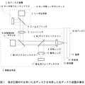
そこで、図1に示すような、蛍光記録材料を記録層に用いた体積型記録媒体の光ディスク10を利用した光ディスク装置1が検討されている(非特許文献1参照)。 Therefore, an optical disc apparatus 1 using a volume recording medium optical disc 10 using a fluorescent recording material as a recording layer as shown in FIG. 1 has been studied (see Non-Patent Document 1).
光ディスク装置1は、サーボ制御のためのサーボ光学系2と、情報の記録又は再生のための情報光学系3とを有している。 The optical disc apparatus 1 has a servo optical system 2 for servo control and an information optical system 3 for recording or reproducing information.
光ディスク装置1は、サーボ光学系2のサーボ用レーザダイオード4から波長約780[nm]のレーザ光でなる赤外光ビームを出射させ、ビームスプリッタ5、リレーレンズ6、第1ダイクロイックミラー7、第2ダイクロイックミラー8、対物レンズ9を介して光ディスク10に照射する。 The optical disc apparatus 1 emits an infrared light beam of a laser beam having a wavelength of about 780 [nm] from the servo laser diode 4 of the servo optical system 2, and the beam splitter 5, the relay lens 6, the first dichroic mirror 7, the first The optical disk 10 is irradiated through the two-dichroic mirror 8 and the objective lens 9.
第1ダイクロイックミラー7は光ビームの波長により透過率及び反射率が異なる、いわゆる波長選択性を有しており、赤外光ビームをほぼ100[%]の割合で反射し、他の波長の光ビームをほぼ100[%]の割合で透過させるようになされている。このため第1ダイクロイックミラー7は、赤外光ビームを反射する。 The first dichroic mirror 7 has so-called wavelength selectivity in which the transmittance and reflectance differ depending on the wavelength of the light beam, reflects the infrared light beam at a rate of approximately 100 [%], and emits light of other wavelengths. The beam is transmitted at a rate of approximately 100 [%]. Therefore, the first dichroic mirror 7 reflects the infrared light beam.
また第2ダイクロイックミラー8は、赤色光ビーム及び赤外光ビームをほぼ100[%]の割合で透過させ、他の波長の光ビームをほぼ100[%]の割合で反射するようになされている。このため第2ダイクロイックミラー8は、赤外光ビームを透過させる。 The second dichroic mirror 8 transmits a red light beam and an infrared light beam at a rate of approximately 100 [%] and reflects light beams of other wavelengths at a rate of approximately 100 [%]. . For this reason, the second dichroic mirror 8 transmits the infrared light beam.
光ディスク10は、基板11と、情報を記録するための記録層12と、光ビームを反射する反射膜13とを有している。 The optical disk 10 includes a substrate 11, a recording layer 12 for recording information, and a reflective film 13 for reflecting a light beam.
記録層12は蛍光記録材料でなり、高い光強度の光ビームを照射されるとその焦点付近において光化学反応が起き、蛍光を発しやすい構造となることで、記録マークが形成されるようになされている。また記録層12において光化学反応が起こった箇所は、光ビームを照射されると、当該照射された光ビームとは異なる波長の光ビームを発生する。 The recording layer 12 is made of a fluorescent recording material, and when irradiated with a light beam with a high light intensity, a photochemical reaction occurs near the focal point, and a structure that easily emits fluorescence is formed, so that a recording mark is formed. Yes. When a photochemical reaction occurs in the recording layer 12, when a light beam is irradiated, a light beam having a wavelength different from that of the irradiated light beam is generated.
続いて光ディスク装置1は、光ディスク10の反射膜13から反射された反射光ビームを、対物レンズ9、第2ダイクロイックミラー8、第1ダイクロイックミラー7、リレーレンズ6を介してビームスプリッタ5へ入射させる。 Subsequently, the optical disc apparatus 1 causes the reflected light beam reflected from the reflective film 13 of the optical disc 10 to enter the beam splitter 5 via the objective lens 9, the second dichroic mirror 8, the first dichroic mirror 7, and the relay lens 6. .
ビームスプリッタ5は反射光ビームの一部を反射し、サーボ用フォトディテクタ14に照射する。サーボ用フォトディテクタ14は検出領域を有しており、検出した光量に応じて検出信号を生成する。 The beam splitter 5 reflects a part of the reflected light beam and irradiates the servo photodetector 14. The servo photo-detector 14 has a detection area, and generates a detection signal according to the detected light amount.
光ディスク装置1は当該検出信号に基づき、図示しないアクチュエータにより対物レンズ9を移動させ、トラッキング制御及びフォーカス制御を行う。 Based on the detection signal, the optical disc apparatus 1 moves the objective lens 9 by an actuator (not shown) to perform tracking control and focus control.
光ディスク装置1は情報を記録する際、情報光学系2のレーザダイオード15から高い光強度でなる波長約660[nm]の赤色光ビームを出射させ、第1ダイクロイックミラー7、第2ダイクロイックミラー8、対物レンズ9を介して光ディスク10の記録層11に照射して記録マークを形成する。 When recording information, the optical disc apparatus 1 emits a red light beam having a wavelength of about 660 [nm] with high light intensity from the laser diode 15 of the information optical system 2, and the first dichroic mirror 7, second dichroic mirror 8, A recording mark is formed by irradiating the recording layer 11 of the optical disc 10 through the objective lens 9.
一方光ディスク装置1は情報を再生する際、情報光学系2のレーザダイオード15から、記録をする際よりも低い光強度でなる赤色光ビームを出射させ、第1ダイクロイックミラー7、第2ダイクロイックミラー8、対物レンズ9を介して赤色光ビームを光ディスク10の記録層11に照射する。 On the other hand, when reproducing information, the optical disk apparatus 1 emits a red light beam having a light intensity lower than that at the time of recording from the laser diode 15 of the information optical system 2, and the first dichroic mirror 7 and the second dichroic mirror 8. The recording layer 11 of the optical disk 10 is irradiated with a red light beam through the objective lens 9.
記録層11は、記録マークに光ビームが照射されると、照射された光ビームとは異なる波長の再生光ビームを発生する。 When the recording layer 11 is irradiated with a light beam, the recording layer 11 generates a reproduction light beam having a wavelength different from that of the irradiated light beam.
光ディスク装置1は、再生光ビームを、対物レンズ9を介して第2ダイクロイックミラー8に入射させる。第2ダイクロイックミラー8は、赤色光ビームとは波長が異なる再生光ビームを反射し、集光レンズ16により集光して再生用フォトディテクタ17に入射させる。 The optical disc apparatus 1 causes the reproduction light beam to enter the second dichroic mirror 8 through the objective lens 9. The second dichroic mirror 8 reflects a reproduction light beam having a wavelength different from that of the red light beam, collects it by the condenser lens 16, and makes it incident on the reproduction photodetector 17.
フォトディテクタ17は検出領域を有しており、検出した光量に応じて再生検出信号を生成する。 The photodetector 17 has a detection area, and generates a reproduction detection signal according to the detected light amount.
光ディスク装置1は当該再生検出信号に基づき、再生検出信号に対して所定の復調処理や復号化処理等を施すことにより再生情報を生成する。 The optical disc apparatus 1 generates reproduction information by performing predetermined demodulation processing, decoding processing, and the like on the reproduction detection signal based on the reproduction detection signal.
図1に示したように、光ディスク装置1においては情報の記録又は再生のための情報光学系3とは別に、フォーカス制御等のサーボ制御を行うためにサーボ光学系2を有している。 As shown in FIG. 1, the optical disc apparatus 1 includes a servo optical system 2 for performing servo control such as focus control, in addition to the information optical system 3 for recording or reproducing information.
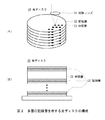
一方光ディスクを大容量化する手法の一つとして、図2に示すような、対物レンズ21により集光された光ビームにより記録マークが作成される記録層22を中間層23で挟み込んだ構造でなる、多層の記録層を有する光ディスク20も検討されている。(非特許文献2参照)。 On the other hand, as one method for increasing the capacity of an optical disk, a recording layer 22 in which a recording mark is created by a light beam condensed by an objective lens 21 is sandwiched between intermediate layers 23 as shown in FIG. Also, an optical disc 20 having a multi-layered recording layer has been studied. (Refer nonpatent literature 2).
光ディスク20における記録層22は、記録用の光ビームを照射されることで光の屈折率を変化させる材料により構成され、記録用光のビームの焦点付近の屈折率が変化することで、記録マークが形成されるようになされている。 The recording layer 22 in the optical disc 20 is made of a material that changes the refractive index of light by being irradiated with a recording light beam, and the recording mark is changed by changing the refractive index near the focal point of the recording light beam. Is formed.
しかしながらこのような光ディスク20を用いた光ディスク装置においても、光ディスク装置1(図1)と同様に、情報の記録又は再生のための情報光学系とは別に、フォーカス制御等のサーボ制御を行うためにサーボ光学系が必要であった。このため光ディスク20を用いた光ディスク装置においては、装置の構成が複雑になってしまっていた。 However, in such an optical disc apparatus using the optical disc 20, as in the optical disc apparatus 1 (FIG. 1), servo control such as focus control is performed separately from the information optical system for recording or reproducing information. A servo optical system was necessary. For this reason, in the optical disk apparatus using the optical disk 20, the structure of the apparatus has become complicated.
本発明は以上の点を考慮してなされたもので、蛍光記録材料を記録層に用いた光ディスクに対して、簡易な構成によりフォーカス制御を行う光ピックアップ及び光ディスク装置を提案しようとするものである。 The present invention has been made in consideration of the above points, and intends to propose an optical pickup and an optical disc apparatus that perform focus control with a simple configuration with respect to an optical disc using a fluorescent recording material as a recording layer. .
かかる問題を解決するため本発明の光ディスク装置においては、光ビームを出射する光源と、光源から光ビームが照射されると情報を表す記録マークの有無に応じて光ビームとは異なる波長の再生光ビームを発生する蛍光記録材料でなる記録層と、当該記録層に隣接し光ビームを反射する反射部とを有する光ディスクに、光ビームの焦点を合わせる対物レンズと、光ディスクの反射部により反射された、光ビームと同等の波長でなる反射光ビームを、再生光ビームから分離する波長選択素子と、波長選択素子により分離された反射光ビームを受光し位置検出信号を生成する反射光検出器と、位置検出信号に基づき、光ビームの光軸方向に関する光ビームの焦点と記録層とのずれを表すフォーカスエラー信号を生成する信号処理部と、フォーカスエラー信号に基づき、対物レンズを光ディスクへ離接する方向へ移動させるレンズ移動部とを設けるようにした。 In order to solve such a problem, in the optical disc apparatus of the present invention, a reproduction light having a wavelength different from that of the light beam according to the presence or absence of a light source that emits a light beam and a recording mark that represents information when the light beam is irradiated from the light source. An optical disk having a recording layer made of a fluorescent recording material that generates a beam and a reflecting portion that reflects the light beam adjacent to the recording layer is reflected by an objective lens that focuses the light beam and the reflecting portion of the optical disc. A wavelength selection element that separates the reflected light beam having the same wavelength as the light beam from the reproduction light beam, a reflected light detector that receives the reflected light beam separated by the wavelength selection element and generates a position detection signal; A signal processing unit that generates a focus error signal indicating a deviation between the focal point of the light beam and the recording layer in the optical axis direction of the light beam based on the position detection signal; Based on the error signal, and to provide a lens moving unit that moves in the direction of contact away the objective lens to the optical disc.
この光ディスク装置では、光ディスクに記録された情報を再生するための光ビームを出射する光源と同一の光源から出射された光ビームに基づき、フォーカス制御を行うことができる。 In this optical disc apparatus, focus control can be performed based on a light beam emitted from the same light source that emits a light beam for reproducing information recorded on the optical disc.
本発明によれば、光ディスクに記録された情報を再生するための光ビームを出射する光源と同一の光源から出射された光ビームに基づき、フォーカス制御を行うことができる。かくして本発明は、蛍光記録材料を記録層に用いた光ディスクに対して、簡易な構成によりフォーカス制御を行う光ピックアップ及び光ディスク装置を実現できる。 According to the present invention, focus control can be performed based on a light beam emitted from the same light source that emits a light beam for reproducing information recorded on an optical disc. Thus, the present invention can realize an optical pickup and an optical disc apparatus that perform focus control with a simple configuration on an optical disc using a fluorescent recording material as a recording layer.
以下、発明を実施するための形態(以下実施の形態とする)について説明する。なお、説明は以下の順序で行う。
1.実施の形態
2.他の実施の形態
Hereinafter, modes for carrying out the invention (hereinafter referred to as embodiments) will be described. The description will be given in the following order.
1. Embodiment 2. FIG. Other embodiments
<1.実施の形態>
[1−1.光ディスクの構成]
まず、本発明において光情報記録媒体として用いられる光ディスク100について説明する。図3(A)に外観図を示すように、光ディスク100は、全体として従来のCD、DVD及びBDと同様に直径約120[mm]の円盤状に構成されており、中央部分に孔部100Hが形成されている。
<1. Embodiment>
[1-1. Configuration of optical disc]
First, an optical disc 100 used as an optical information recording medium in the present invention will be described. As shown in the external view in FIG. 3A, the optical disc 100 as a whole is formed in a disk shape having a diameter of about 120 [mm], similar to the conventional CD, DVD and BD, and has a hole 100H at the center. Is formed.
また光ディスク100は、図3(B)に断面図を示すように、情報を記録するための記録層101とスペーサとしての中間層102とが交互に重ね合わされ、さらに基板103及び104により当該記録層101及び中間層102を両面から挟むように構成されている。 Further, as shown in the cross-sectional view of FIG. 3B, the optical disc 100 has a recording layer 101 for recording information and an intermediate layer 102 as a spacer alternately stacked. 101 and the intermediate layer 102 are sandwiched from both sides.
基板103及び104は、例えばポリカーボネイトやガラス等の材料により構成されており、いずれも一面から入射される光をその反対面へ高い透過率で透過させるようになされている。また基板103及び104は、ある程度の強度を有しており、記録層101及び中間層102を保護する役割も担うようになされている。 The substrates 103 and 104 are made of, for example, a material such as polycarbonate or glass, and both of them transmit light incident from one surface to the opposite surface with high transmittance. The substrates 103 and 104 have a certain level of strength, and also serve to protect the recording layer 101 and the intermediate layer 102.
中間層102は、基板103及び104と同様に、一面から入射される光をその反対面へ高い透過率で透過させるようになされている。 Similar to the substrates 103 and 104, the intermediate layer 102 transmits light incident from one surface to the opposite surface with high transmittance.
記録層101は、高い光強度の光ビームを照射されるとその焦点付近において2光子吸収反応が起き、蛍光を発しやすい構造となることで記録マークが形成される蛍光記録材料でなり、波長約405[nm]でなる青色光ビームに反応するようになされている。 The recording layer 101 is a fluorescent recording material in which a recording mark is formed by a two-photon absorption reaction that occurs near the focal point when irradiated with a light beam having a high light intensity and has a structure that easily emits fluorescence. It is designed to respond to a blue light beam of 405 [nm].
記録層101は上記記録マークに青色光ビームを照射されると、いわゆるストークスシフトにより、当該青色光ビームよりも長い波長でなる再生光ビームを発生する。 When the recording mark 101 is irradiated with a blue light beam, the recording layer 101 generates a reproduction light beam having a longer wavelength than the blue light beam by a so-called Stokes shift.
また光ディスク100は、記録層101と中間層102との境界面であり記録層101の片面の基板103側に、反射層としての反射膜105が形成されている。反射膜105は波長選択性を有していない誘電体多層膜等でなり、照射された光ビームを例えば1[%]の割合で反射する。 In the optical disc 100, a reflective film 105 as a reflective layer is formed on the substrate 103 side on one side of the recording layer 101, which is a boundary surface between the recording layer 101 and the intermediate layer. The reflective film 105 is made of a dielectric multilayer film or the like that does not have wavelength selectivity, and reflects the irradiated light beam at a rate of 1 [%], for example.
また反射膜105は、トラッキングサーボ用の案内溝を形成しており、具体的には、一般的なBD−R(Recordable)ディスク等と同様のランド及びグルーブにより螺旋状のトラックを形成している。このトラックには、所定の記録単位ごとに一連の番号でなるアドレスが付されており、情報を記録又は再生するトラックを当該アドレスにより特定し得るようになされている。 Further, the reflective film 105 forms a guide groove for tracking servo. Specifically, a spiral track is formed by lands and grooves similar to a general BD-R (Recordable) disk or the like. . This track is given an address consisting of a series of numbers for each predetermined recording unit, and the track on which information is recorded or reproduced can be specified by the address.
なお反射膜105(すなわち記録層101と中間層102との境界面)には、案内溝に代えてピット等が形成され、或いは案内溝とピット等とが組み合わされていても良い。 Note that pits or the like may be formed on the reflective film 105 (that is, the boundary surface between the recording layer 101 and the intermediate layer 102) instead of the guide grooves, or the guide grooves and pits may be combined.
この反射膜105は、基板103側から光ビームが照射された場合、これを当該基板103側へ反射する。以下、このとき反射された光ビームを反射光ビームと呼ぶ。 When a light beam is irradiated from the substrate 103 side, the reflection film 105 reflects the light toward the substrate 103 side. Hereinafter, the light beam reflected at this time is referred to as a reflected light beam.
この反射光ビームは、例えば光ディスク装置において、目標とするトラック(以下目標トラックと呼ぶ)に対して、所定の対物レンズ47により集光された光ビームの焦点Fを合わせるため、対物レンズ47の位置制御(すなわちフォーカス制御及びトラッキング制御)に用いられることが想定されている。 For example, in the optical disc apparatus, the reflected light beam is used to adjust the focus F of the light beam condensed by a predetermined objective lens 47 to a target track (hereinafter referred to as a target track). It is assumed to be used for control (that is, focus control and tracking control).
実際上、光ディスク100に情報が記録されるとき、位置制御された対物レンズ47により青色光ビームが集光され、例えば反射膜105Cの目標トラックに合焦される。
In practice, when information is recorded on the optical disc 100, the blue light beam is collected by the position-controlled objective lens 47, and is focused on the target track of the
このとき青色光ビームが記録処理時に使用される光強度でなる光ビームL1である場合、反射膜105Cから対物レンズ47に対して離隔する方向に隣接している記録層101C内には、当該光ビームL1が集光されて所定強度以上となった部分(すなわち焦点F周辺)で2光子吸収反応が起き、記録マークが形成される。
At this time, when the blue light beam is the light beam L1 having the light intensity used in the recording process, the light is present in the recording layer 101C adjacent to the objective film 47 in the direction away from the
ここで、図1に示した体積型記録媒体の光ディスク10においては、サーボ制御を行う赤外光ビームの焦点は反射膜13に合焦しており、一方、情報の記録又は再生を行う赤色光ビームの焦点は、赤外光ビームの焦点から光軸方向へ所定の距離を経て記録層12内部に合焦していた。このように光ディスク10においては、サーボ制御と情報の記録又は再生とで光ビームの焦点位置が異なっていた。 Here, in the optical disk 10 of the volume type recording medium shown in FIG. 1, the focus of the infrared light beam for servo control is focused on the reflection film 13, while the red light for recording or reproducing information is used. The focal point of the beam was focused inside the recording layer 12 through a predetermined distance in the optical axis direction from the focal point of the infrared light beam. As described above, in the optical disk 10, the focal position of the light beam differs between servo control and information recording or reproduction.
これに対して光ディスク100では、それぞれの記録層101に対して反射膜105が隣接しており、反射膜105に焦点が合うと、当該反射膜105に隣接している記録層101にも焦点が合っているとみなすことができる。 On the other hand, in the optical disc 100, the reflective film 105 is adjacent to each recording layer 101, and when the reflective film 105 is focused, the recording layer 101 adjacent to the reflective film 105 is also focused. It can be regarded as suitable.
一方、光ディスク100は、情報が再生されるとき、当該情報を記録したときと同様に、対物レンズ47により集光された、青色光ビームでなる光ビームL1が反射膜105C(すなわち記録層101C)の目標トラックに合焦されるよう、当該対物レンズ47が位置制御されるようになされている。
On the other hand, in the optical disc 100, when information is reproduced, the light beam L1, which is a blue light beam condensed by the objective lens 47, is reflected on the
このとき焦点Fの位置に記録されている記録マークは蛍光を発生しやすい構造になっており、青色光ビームよりも長い波長でなる再生光ビームを発生する。 At this time, the recording mark recorded at the position of the focal point F has a structure that easily generates fluorescence, and generates a reproduction light beam having a longer wavelength than the blue light beam.
一方、記録マークを記録しなかった箇所(すなわち未記録部分)に対して青色光ビームでなる光ビームL1を照射されると、再生光ビームは発生されない。 On the other hand, when the portion where the recording mark is not recorded (that is, the unrecorded portion) is irradiated with the light beam L1 which is a blue light beam, the reproduction light beam is not generated.
このように光ディスク100は、記録済みの情報が再生される場合、反射膜105により青色光でなる光ビームL1を反射して反射光ビームL2とし、当該反射膜105に対応した記録層101の記録マークから、光ビームL1よりも長い波長でなる再生光ビームを発生させるようになされている。 As described above, when recorded information is reproduced, the optical disc 100 reflects the light beam L1 of blue light by the reflective film 105 to be a reflected light beam L2, and records on the recording layer 101 corresponding to the reflective film 105. A reproduction light beam having a longer wavelength than the light beam L1 is generated from the mark.
[1−2.光ディスク装置の構成]
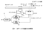
次に、上述した光ディスク100に対応した光ディスク装置30について説明する。光ディスク装置30は、図4に示すように、制御部31により全体を統括制御するようになされている。
[1-2. Configuration of optical disc apparatus]
Next, an optical disk device 30 corresponding to the above-described optical disk 100 will be described. As shown in FIG. 4, the optical disk device 30 is configured to perform overall control by a
制御部31は、図示しないCPU(Central Processing Unit)を中心に構成されており、図示しないROM(Read Only Memory)から基本プログラムや情報記録プログラム等の各種プログラムを読み出し、これらを図示しないRAM(Random Access Memory)に展開することにより、情報記録処理等の各種処理を実行するようになされている。
The
例えば制御部31は、光ディスク100が装填された状態で、図示しない外部機器等から情報記録命令、記録情報及び記録アドレス情報を受け付けると、駆動命令及び記録アドレス情報を駆動制御部32へ供給すると共に、記録情報を信号処理部33へ供給する。因みに記録アドレス情報は、光ディスク100の反射膜105に付されたアドレスのうち、記録情報を記録すべきアドレスを示す情報である。
For example, when the
駆動制御部32は、駆動命令に従い、スピンドルモータ34を駆動制御することにより光ディスク100を所定の回転速度で回転させる。これと共に、スレッドモータ35を駆動制御することにより、光ピックアップ36を移動軸Gに沿って光ディスク100の径方向(すなわち内周方向又は外周方向)における記録アドレス情報に対応した位置へ移動させる。
The
信号処理部33は、供給された記録情報に対して所定の符号化処理や変調処理等の各種信号処理を施すことにより記録信号を生成し、これを光ピックアップ36へ供給する。
The
光ピックアップ36は、駆動制御部32の制御に基づいてフォーカス制御及びトラッキング制御を行うことにより、光ディスク100の反射膜105における記録アドレス情報により示されるトラック(目標トラック)に光ビームL1の照射位置を合わせる。これにより光ピックアップ36は、当該反射膜105に対応した記録層101に信号処理部33からの記録信号に応じた記録マークを記録するようになされている。
The optical pickup 36 performs focus control and tracking control based on the control of the
また制御部31は、例えば外部機器(図示せず)から情報再生命令及び当該記録情報のアドレスを示す再生アドレス情報を受け付けると、駆動制御部32に対して駆動命令を供給すると共に、再生処理命令を信号処理部33へ供給する。
When the
駆動制御部32は、情報を記録する場合と同様、スピンドルモータ34を駆動制御することにより光ディスク100を所定の回転速度で回転させると共に、スレッドモータ35を駆動制御することにより光ピックアップ36を再生アドレス情報に対応した位置へ移動させる。
As in the case of recording information, the
光ピックアップ36は、駆動制御部32の制御に基づいてフォーカス制御及びトラッキング制御を行うことにより、光ディスク100の反射膜105における再生アドレス情報により示されるトラック(すなわち目標トラック)に光ビームL1の照射位置を合わせ、所定光量の光ビームL1を照射する。このとき光ピックアップ36は、光ディスク100における記録層101の記録マークから発生される再生光ビームを検出し、その光量に応じた検出信号を信号処理部33へ供給するようになされている。
The optical pickup 36 performs focus control and tracking control based on the control of the
以下では、光ディスク装置30が記録又は再生を行う対象の記録層及び当該記録層に対応した反射膜(例えば記録層101C及び反射膜105C)とをまとめて記録対象層100Tとも呼ぶ。
Hereinafter, the recording layer to be recorded or reproduced by the optical disc apparatus 30 and the reflective films (for example, the recording layer 101C and the
信号処理部33は、供給された検出信号に対して所定の復調処理や復号化処理等の各種信号処理を施すことにより再生情報を生成し、この再生情報を制御部31へ供給する。これに応じて制御部31は、この再生情報を外部機器(図示せず)へ送出するようになされている。
The
このように光ディスク装置30は、制御部31によって光ピックアップ36を制御することにより、光ディスク100の記録対象層100Tにおける目標トラックに情報を記録し、また当該目標トラックから情報を再生するようになされている。
As described above, the optical disc apparatus 30 controls the optical pickup 36 by the
[1−3.光ピックアップの構成]
[1−3−1.フォーカス制御及びトラッキングエラー制御]
次に、図5に示す光ピックアップ36の構成について説明する。また、記録対象層100Tは、記録層101C及び反射膜105Cとする。
[1-3. Configuration of optical pickup]
[1-3-1. Focus control and tracking error control]
Next, the configuration of the optical pickup 36 shown in FIG. 5 will be described. The
レーザダイオード41は、波長約405[nm]の青色レーザ光を出射し得るようになされている。実際上レーザダイオード41は、制御部31(図4)の制御に基づいて発散光でなる所定光量の光ビームL1を発射し、コリメータレンズ42へ入射させる。コリメータレンズ42は、光ビームL1を発散光から平行光に変換し偏光ビームスプリッタ43へ入射させる。 The laser diode 41 can emit blue laser light having a wavelength of about 405 [nm]. In practice, the laser diode 41 emits a light beam L1 having a predetermined light amount, which is a divergent light, based on the control of the control unit 31 (FIG. 4) and makes it incident on the collimator lens. The collimator lens 42 converts the light beam L 1 from diverging light into parallel light and makes it incident on the polarization beam splitter 43.
偏光ビームスプリッタ43は、反射透過面43Sにおいて、光ビームの偏光方向により異なる割合で当該光ビームを反射又は透過させるようになされている。例えば反射透過面43Sは、p偏光の光ビームを約100[%]の割合で透過させ、s偏光の光ビームを約100[%]の割合で反射するようになされている。 The polarization beam splitter 43 is configured to reflect or transmit the light beam on the reflection / transmission surface 43S at a different rate depending on the polarization direction of the light beam. For example, the reflection / transmission surface 43S transmits a p-polarized light beam at a rate of about 100 [%] and reflects an s-polarized light beam at a rate of about 100 [%].
実際上、偏光ビームスプリッタ43は、反射透過面43Sにおいてp偏光でなる光ビームL1をそのまま通過させ、ダイクロイックプリズム44へ入射させる。 In practice, the polarization beam splitter 43 passes the light beam L1 made of p-polarized light as it is on the reflection / transmission surface 43S and makes it incident on the dichroic prism 44.
ダイクロイックプリズム44の反射透過面44Sは、光ビームの波長により透過率及び反射率が異なる、いわゆる波長選択性を有しており、青色光ビームを約100[%]の割合で透過させ、他の波長でなる光ビームをほぼ100[%]の割合で反射するようになされている。このためダイクロイックプリズム44は、反射透過面44Sにおいて光ビームL1を透過させ、1/4波長板45へ入射させる。
The reflection /
1/4波長板45は、光ビームL1を直線偏光から例えば左円偏光に変換してリレーレンズ46へ入射させる。リレーレンズ46は、光ビームL1を平行光から発散光に変換し、対物レンズ47へ入射させる。 The quarter-wave plate 45 converts the light beam L1 from linearly polarized light into, for example, left circularly polarized light and makes it incident on the relay lens 46. The relay lens 46 converts the light beam L1 from parallel light into divergent light and makes it incident on the objective lens 47.
ここでリレーレンズ46は、図示しないアクチュエータにより光ビームL1の光軸方向に移動されるようになされている。実際上、リレーレンズ46は、制御部31(図4)の制御に基づきアクチュエータによって移動されることにより、出射される光ビームL1の発散状態を変化させる。これによりリレーレンズ46は、光ビームL1が集光され光ディスク100の目標トラックに到達した際に生じる球面収差と逆特性となるような球面収差を当該光ビームL1に予め与え、光ビームL1の目標トラック到達時における球面収差を補正し得るようになされている。 Here, the relay lens 46 is moved in the optical axis direction of the light beam L1 by an actuator (not shown). In practice, the relay lens 46 is moved by the actuator based on the control of the control unit 31 (FIG. 4), thereby changing the divergence state of the emitted light beam L1. As a result, the relay lens 46 preliminarily gives the light beam L1 spherical aberration that is opposite to the spherical aberration that occurs when the light beam L1 is collected and reaches the target track of the optical disc 100, and the target of the light beam L1. The spherical aberration at the time of reaching the track can be corrected.
対物レンズ47は、光ビームL1を集光し、記録対象層100Tへ向けて照射する。このとき光ビームL1は、図3に示したように、基板103を透過し記録対象層100Tの反射膜105Cにおいてその一部が反射されて光ビームL1と反対方向へ向かい、その偏光方向が右円偏光でなる反射光ビームL2となる。
The objective lens 47 collects the light beam L1 and irradiates the
反射光ビームL2は、対物レンズ47によって収束光に変換された後、リレーレンズ46を介して1/4波長板45へ入射される。1/4波長板45は、右円偏光でなる反射光ビームL2をs偏光に変換し、ダイクロイックプリズム44へ入射させる。 The reflected light beam L2 is converted into convergent light by the objective lens 47 and then incident on the quarter-wave plate 45 via the relay lens 46. The quarter-wave plate 45 converts the reflected light beam L <b> 2 made of right circularly polarized light into s-polarized light and makes it incident on the dichroic prism 44.
ダイクロイックプリズム44は、反射透過面44Sにおいて、青色光でなる反射光ビームL2を透過させ、偏光ビームスプリッタ43へ入射させる。偏光ビームスプリッタ43は、s偏光でなる反射光ビームL2を反射し、集光レンズ48へ入射させる。
The dichroic prism 44 transmits the reflected light beam L2 made of blue light through the reflection /
集光レンズ48は、反射光ビームL2を集光し、シリンドリカルレンズ49により非点収差を持たせた上で当該反射光ビームL2をサーボ用フォトディテクタ50へ照射する。
The condensing lens 48 condenses the reflected light beam L <b> 2, gives astigmatism by the cylindrical lens 49, and irradiates the reflected light beam L <b> 2 to the
光ピックアップ36においては、対物レンズ47により光ビームL1が集光され光ディスク100の記録対象層100Tへ照射されるときの合焦状態が、集光レンズ48により反射光ビームL2が集光されサーボ用フォトディテクタ50に照射されるときの合焦状態に反映されるよう、各種光学部品の光学的位置が調整されている。
In the optical pickup 36, the focused state when the light beam L1 is condensed by the objective lens 47 and applied to the
また対物レンズ47は、2軸アクチュエータ54(図4)により、光ディスク100に対する近接方向又は離隔方向であるフォーカス方向と、光ディスク100の内周側方向又は外周側方向であるトラッキング方向との2軸方向へ駆動され得るようになされている。 In addition, the objective lens 47 is biaxially driven by a biaxial actuator 54 (FIG. 4), which is a focus direction which is a close direction or a separation direction with respect to the optical disc 100 and a tracking direction which is an inner peripheral side direction or an outer peripheral side direction. Can be driven to.
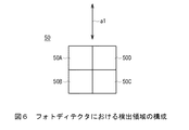
サーボ用フォトディテクタ50は、図6に示すように、反射光ビームL2が照射される面上に、格子状に分割された4つの検出領域50A、50B、50C及び50Dを有している。因みに矢印a1により示される方向(図中の縦方向)は、光ビームL1が反射膜105(図3)に照射されるときの、トラックの走行方向に対応している。
As shown in FIG. 6, the
サーボ用フォトディテクタ50は、検出領域50A、50B、50C及び50Dにより反射光ビームL2の一部をそれぞれ検出し、このとき検出した光量に応じて位置検出信号SDA、SDB、SDC及びSDDをそれぞれ生成して、これらを信号処理部33(図4)へ送出する。
The
信号処理部33は、いわゆる非点収差法によるフォーカス制御を行うようになされており、次に示す(1)式に従ってフォーカスエラー信号SFEを算出し、これを駆動制御部32へ供給する。
The
![]()
![]()
このフォーカスエラー信号SFEは、光ビームL1の焦点Fと光ディスク100の記録対象層100Tとの光ビームL1の光軸方向のずれ量を表すことになる。ここで、光ビームL1が目標トラックからフォーカス方向に焦点がずれてデフォーカスした場合、サーボ用フォトディテクタ50に照射される際のスポットの形状が、デフォーカス量に応じて変化することとなる。
The focus error signal SFE represents the amount of deviation in the optical axis direction of the light beam L1 between the focal point F of the light beam L1 and the
また信号処理部33は、いわゆるプッシュプル法によるトラッキング制御を行うようになされており、次に示す(2)式に従ってトラッキングエラー信号STEを算出し、これを駆動制御部32へ供給する。
The
![]()
![]()
このトラッキングエラー信号STEは、焦点Fと光ディスク100の記録対象層100Tにおける目標トラックとの径方向のずれ量を表すことになる。
The tracking error signal STE represents a radial shift amount between the focal point F and the target track in the
駆動制御部32は、フォーカスエラー信号SFEを基にフォーカス駆動信号SFDを生成し、当該フォーカス駆動信号SFDを2軸アクチュエータ54へ供給する。これにより駆動制御部32は、光ビームL1が光ディスク100の記録対象層100Tに合焦するよう、対物レンズ47をフィードバック制御(すなわちフォーカス制御)する。
The
また駆動制御部32は、トラッキングエラー信号STEを基にトラッキング駆動信号STDを生成し、当該トラッキング駆動信号STDを2軸アクチュエータ54へ供給することにより、光ビームL1が光ディスク100の記録対象層100Tにおける目標トラックに合焦するよう、対物レンズ47をフィードバック制御(すなわちトラッキング制御)する。
Further, the
このように光ピックアップ36は、光ビームL1を光ディスク100の記録対象層100Tに照射し、その反射光である反射光ビームL2の受光結果を信号処理部33へ供給するようになされている。これに応じて駆動制御部32は、当該光ビームL1を当該記録対象層100Tの目標トラックに合焦させるよう、対物レンズ47のフォーカス制御及びトラッキング制御を行うようになされている。
In this way, the optical pickup 36 irradiates the
[1−3−2.光ディスクに対する情報の記録]
光ディスク100に情報を記録する場合、光ディスク装置30の制御部31(図4)は、上述したように、外部機器(図示せず)等から情報記録命令、記録情報及び記録アドレス情報を受け付けると、駆動命令及び記録アドレス情報を駆動制御部32へ供給すると共に、記録情報を信号処理部33へ供給する。
[1-3-2. Recording information on optical disc]
When recording information on the optical disc 100, the control unit 31 (FIG. 4) of the optical disc device 30 receives an information recording command, recording information, and recording address information from an external device (not shown) as described above. The drive command and the recording address information are supplied to the
このとき駆動制御部32は、光ピックアップ36のレーザダイオード41から、記録処理時よりも低い光強度の青色光でなる光ビームL1を光ディスク100に照射させる。また駆動制御部32は、その反射光である反射光ビームL2の検出結果を基に、対物レンズ47のフォーカス制御及びトラッキング制御(すなわち位置制御)を行うことにより、光ビームL1の焦点Fを記録アドレス情報に対応した目標トラックに追従させる。
At this time, the
続いて駆動制御部32は、光ピックアップ36のレーザダイオード41から高い光強度でなる青色光の光ビームL1を出射させる。
Subsequently, the
光ビームL1は、コリメータレンズ42、偏光ビームスプリッタ43、ダイクロイックプリズム44、1/4波長板45、リレーレンズ46、対物レンズ47を介して光ディスク100の目標トラックに合焦される。 The light beam L1 is focused on the target track of the optical disc 100 via the collimator lens 42, the polarization beam splitter 43, the dichroic prism 44, the quarter wavelength plate 45, the relay lens 46, and the objective lens 47.
上述したように光ディスク100においては、記録対象層100Tは記録層101と、当該記録層に隣接する反射膜105とが一体になっているとみなせる。このため光ビームL1の焦点Fが反射膜105に合焦していても、当該反射膜105に対応した記録層101内に記録マークを形成させることができる。
As described above, in the optical disc 100, the
このとき記録層101内には、光ビームL1が集光されて所定強度以上となった部分(すなわち焦点F周辺)で2光子吸収反応が起き、蛍光を発生しやすい構造となることにより、記録マークが形成される。 At this time, the recording layer 101 has a structure in which a two-photon absorption reaction occurs in a portion where the light beam L1 is condensed and becomes a predetermined intensity or more (that is, around the focal point F), and the structure easily generates fluorescence. A mark is formed.
ところで信号処理部33(図4)は、外部機器(図示せず)等から供給される記録情報を基に、例えば値「0」又は「1」のバイナリデータを表す記録信号を生成する。これに応じてレーザダイオード41は、例えば記録信号が値「1」である時に光ビームL1を出射し、記録信号が値「0」である時に光ビームL1を出射しないようになされている。 By the way, the signal processing unit 33 (FIG. 4) generates a recording signal representing binary data having a value “0” or “1” based on recording information supplied from an external device (not shown) or the like. In response to this, the laser diode 41 emits the light beam L1 when the recording signal has the value “1”, for example, and does not emit the light beam L1 when the recording signal has the value “0”.
このように光ディスク装置30では、記録信号が値「1」のときには光ディスク100の記録層101内に記録マークを形成し、当該記録信号が値「0」のときには当該記録マークを形成しない。 As described above, in the optical disc apparatus 30, a recording mark is formed in the recording layer 101 of the optical disc 100 when the recording signal has the value “1”, and no recording mark is formed when the recording signal has the value “0”.
これにより光ディスク装置30は、当該記録マークの有無により焦点Fの位置に記録信号の値「1」又は「0」を記録することができ、結果的に記録情報を光ディスク100の記録層101に記録することができる。 As a result, the optical disc apparatus 30 can record the value “1” or “0” of the recording signal at the position of the focal point F depending on the presence or absence of the recording mark. As a result, the recording information is recorded on the recording layer 101 of the optical disc 100. can do.
[1−3−3.光ディスクからの情報の再生]
光ディスク100から情報を再生する場合、光ディスク装置30の制御部31(図4)は、光ピックアップ36のレーザダイオード41から青色光でなる光ビームL1を光ディスク100に照射させる。
[1-3-3. Information playback from optical disc]
When reproducing information from the optical disc 100, the control unit 31 (FIG. 4) of the optical disc apparatus 30 irradiates the optical disc 100 with the light beam L 1 made of blue light from the laser diode 41 of the optical pickup 36.
光ビームL1は、コリメータレンズ42、偏光ビームスプリッタ43、ダイクロイックプリズム44、1/4波長板45、リレーレンズ46、対物レンズ47を介して光ディスク100の目標トラックに合焦される。 The light beam L1 is focused on the target track of the optical disc 100 via the collimator lens 42, the polarization beam splitter 43, the dichroic prism 44, the quarter wavelength plate 45, the relay lens 46, and the objective lens 47.
制御部31は、反射層105により反射された青色光でなる反射光ビームL2の検出結果を基に、駆動制御部32により対物レンズ47のフォーカス制御及びトラッキング制御(すなわち位置制御)を行わせる。
The
またこのとき上記反射層105に対応した記録層101の目標トラックに記録マークが形成されていると、当該記録マークは照射された光ビームに応じて蛍光を発生しやすい構造となっているため、光ビームL1よりも長い波長でなる再生光ビームL3を発生する。 At this time, if a recording mark is formed on the target track of the recording layer 101 corresponding to the reflective layer 105, the recording mark has a structure that easily generates fluorescence according to the irradiated light beam. A reproduction light beam L3 having a wavelength longer than that of the light beam L1 is generated.
再生光ビームL3は、対物レンズ47、リレーレンズ46及び1/4波長板45を介してダイクロイックプリズム44に入射される。 The reproduction light beam L3 is incident on the dichroic prism 44 through the objective lens 47, the relay lens 46, and the quarter wavelength plate 45.
ダイクロイックプリズム44の反射透過面44Sは、青色光以外の波長でなる光ビームをほぼ100[%]の割合で反射するようになされている。このためダイクロイックプリズム44は、当該反射透過面44Sにおいて再生光ビームL3を反射し、集光レンズ51へ入射させる。
The reflection /
集光レンズ51は、再生光ビームL3を集光し、ピンホール板52を介して再生用フォトディテクタ53へ照射させる。 The condensing lens 51 condenses the reproducing light beam L3 and irradiates the reproducing photodetector 53 via the pinhole plate 52.
ここでピンホール板52は孔部を有しており、当該孔部の内部に再生光ビームL3の焦点を位置させるよう配置されているため、当該再生光ビームL3をそのまま通過させることになる。 Here, since the pinhole plate 52 has a hole portion and is arranged so that the focal point of the reproduction light beam L3 is positioned inside the hole portion, the reproduction light beam L3 passes through as it is.
このためピンホール板52は、例えば光ディスク100における基板103の表面や、目標トラックとは異なる位置にある記録マーク等から反射されるような焦点の異なる光(以下、これを迷光LNと呼ぶ)をほぼ遮断することになる。 For this reason, the pinhole plate 52 emits light with different focal points (hereinafter referred to as stray light LN) that is reflected from, for example, the surface of the substrate 103 in the optical disc 100 or a recording mark at a position different from the target track. Almost cut off.
再生用フォトディテクタ53には、検出領域が設けれており、当該検出領域により再生光ビームL3を検出し、このとき検出した光量に応じて再生検出信号を生成して、これらを信号処理部33(図4)へ送出する。 The reproduction photo detector 53 is provided with a detection region. The reproduction light beam L3 is detected by the detection region, and a reproduction detection signal is generated according to the detected light amount. 4).
かくして光ディスク装置30の制御部31は、光ディスク100の記録層101内に記録されている記録マークから、光ビームL1とは異なる波長の再生光ビームL3を発生させ、これを受光することにより、記録マークが記録されていることを検出することができる。
Thus, the
ここで光ディスク装置30は、焦点Fの位置、すなわち目標トラックに記録マークが記録されていなかった場合、当該焦点Fの位置からは再生光ビームL3が発生しないため、光ピックアップ36により、当該再生光ビームL3を受光しなかったことを示す再生検出信号を生成することになる。 Here, when the recording mark is not recorded on the position of the focal point F, that is, the target track, the optical disk device 30 does not generate the reproducing light beam L3 from the position of the focal point F. A reproduction detection signal indicating that the beam L3 has not been received is generated.
これに応じて信号処理部33は、再生検出信号を基に、再生光ビームL3が検出されたか否かを値「1」又は「0」として認識し、この認識結果を基に再生情報を生成する。
In response to this, the
このように光ディスク装置30では、光ディスク100の記録層101内の焦点Fの位置(目標トラック)に記録マークが形成されているときには再生光ビームL3を受光し、当該記録マークが形成されていないときには再生光ビームL3を受光しない。 As described above, in the optical disc apparatus 30, the reproduction light beam L3 is received when the recording mark is formed at the position of the focal point F (target track) in the recording layer 101 of the optical disc 100, and when the recording mark is not formed. The reproduction light beam L3 is not received.
これにより光ディスク装置30は、焦点Fの位置に値「1」又は「0」のいずれが記録されているかを認識することができ、結果的に光ディスク100の記録層101に記録された情報を再生することができる。 As a result, the optical disc apparatus 30 can recognize whether the value “1” or “0” is recorded at the position of the focal point F, and reproduces the information recorded on the recording layer 101 of the optical disc 100 as a result. can do.
[1−4.動作及び効果]
以上の構成において光ディスク装置30の制御部31は、光ディスク100から情報を再生する際、レーザダイオード41から青色光でなる光ビームL1を当該光ディスク100の記録対象層100Tに照射させる。
[1-4. Operation and effect]
In the above configuration, when reproducing information from the optical disc 100, the
記録対象層100Tにおける反射膜105により反射された、光ビームL1と同様の波長でなる反射光ビームL2は、ダイクロイックプリズム44を透過し、偏光ビームスプリッタ43により反射されてサーボ用フォトディテクタ50に入射する。
The reflected light beam L2 having the same wavelength as the light beam L1 reflected by the reflective film 105 in the
制御部31は、反射光ビームL2の検出結果を基に、対物レンズ38のフォーカス制御及びトラッキング制御を行い、光ビームL1の焦点Fを目標トラックに追従させる。
The
また記録対象層100Tにおける記録層101に形成されている記録マークは、光ビームL1を照射されると当該光ビームL1よりも長い波長でなる再生光ビームL3を発生する。
Further, when the recording mark formed on the recording layer 101 in the
再生光ビームL3は、ダイクロイックプリズム44に入射され、青色光以外の波長でなる光ビームをほぼ100[%]の割合で反射する反射透過面44Sにより反射されて、集光レンズ51を介して再生用フォトディテクタ53に入射する。
The reproduction light beam L3 is incident on the dichroic prism 44, is reflected by the reflection /
光ディスク装置30の信号処理部33は、再生用フォトディテクタ53により生成された再生検出信号を基に、再生情報を生成する。
The
これにより光ディスク装置30は、反射光ビームL2よりも微弱な光量である再生光ビームL3を、反射光ビームL2から分離することができ、光ディスク100に記録されている情報を高い精度で再生することができる。 As a result, the optical disc apparatus 30 can separate the reproduction light beam L3, which has a weaker amount of light than the reflected light beam L2, from the reflected light beam L2, and reproduce information recorded on the optical disc 100 with high accuracy. Can do.
また、図1に示した体積型記録媒体の光ディスク10においては、サーボ制御を行う反射膜13の位置と、情報の記録を行う記録層12の位置とが隔たれていた。このため光ディスク装置1は、光ビームの焦点をそれぞれ反射膜13と記録層12とに合わせる必要があった。 Further, in the optical disk 10 of the volume type recording medium shown in FIG. 1, the position of the reflective film 13 that performs servo control and the position of the recording layer 12 that records information are separated. For this reason, the optical disk apparatus 1 needs to focus the light beam on the reflective film 13 and the recording layer 12, respectively.
これにより光ディスク装置1は、サーボ制御を行う赤外光ビームと、情報の再生を行う赤色光ビームとの、2つの焦点をある程度離隔させていた。 As a result, the optical disc apparatus 1 separates the two focal points of the infrared light beam for servo control and the red light beam for reproducing information to some extent.
これに対して光ディスク100では、それぞれの記録層101に対して反射膜105が隣接しており、反射膜105に光ビームの焦点が合うと、当該反射膜105に対応した記録層101にも当該光ビームの焦点が合っているとみなすことができる。 On the other hand, in the optical disc 100, the reflective film 105 is adjacent to each recording layer 101. When the light beam is focused on the reflective film 105, the recording layer 101 corresponding to the reflective film 105 also has the recording layer 101. It can be considered that the light beam is in focus.
このため光ディスク装置30は、光ビームL1の焦点Fを記録対象層105に合焦させるだけで、サーボ制御と情報の再生とを行うことができる。 For this reason, the optical disc apparatus 30 can perform servo control and information reproduction only by focusing the focal point F of the light beam L1 on the recording target layer 105.
これにより光ディスク装置30では、サーボ制御と情報の再生とで異なる位置に焦点を合わせるための複数のレーザダイオードを設ける必要がなく、簡易な構成によりサーボ制御を行うことができる。 As a result, in the optical disc apparatus 30, it is not necessary to provide a plurality of laser diodes for focusing at different positions for servo control and information reproduction, and servo control can be performed with a simple configuration.
また、仮に光ディスク100に反射膜105がない場合、光ディスク装置30は光ディスク100から情報を再生する際、記録層101から発生する再生光ビームL3を基にフォーカス制御を行うことも考えられる。 If the optical disc 100 does not have the reflective film 105, the optical disc apparatus 30 may perform focus control based on the reproduction light beam L3 generated from the recording layer 101 when reproducing information from the optical disc 100.
しかしながら蛍光記録材料により構成された記録層101から発生した再生光ビームL3においては、目標トラックからフォーカス方向に焦点がずれてデフォーカスした場合、サーボ用フォトディテクタ50に照射される際のスポットの形状が、デフォーカス量に応じて変化しないことがある。このため光ディスク装置30は、安定的にフォーカス制御を行えない恐れがある。
However, in the reproduction light beam L3 generated from the recording layer 101 made of the fluorescent recording material, when the focus is shifted from the target track in the focus direction and defocused, the shape of the spot when irradiated to the
これに対して光ディスク装置30は、サーボ用フォトディテクタ50に照射される際のスポットの形状がデフォーカス量に応じて変化する、反射膜105により反射された反射光ビームL2を用いることで、安定的にフォーカス制御を行うことができる。
On the other hand, the optical disc apparatus 30 uses the reflected light beam L2 reflected by the reflective film 105 in which the shape of the spot when irradiating the
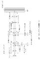
また、光ピックアップ36におけるダイクロイックプリズム44は、偏光ビームスプリッタ43よりも先に再生光ビームL3が入射されるよう配置される。ここで、光ピックアップ36との比較用に、図7に示す仮想的な光ピックアップ136について検討する。 Further, the dichroic prism 44 in the optical pickup 36 is arranged so that the reproduction light beam L 3 is incident before the polarization beam splitter 43. Here, for comparison with the optical pickup 36, the virtual optical pickup 136 shown in FIG.
光ピックアップ136は光ピックアップ36と比較して、偏光ビームスプリッタ43、集光レンズ48、シリンドリカルレンズ49及びサーボ用フォトディテクタ50に代えて、ダイクロイックプリズム144、集光レンズ151、ピンホール板152及び再生用フォトディテクタ153が設けられている。
Compared to the optical pickup 36, the optical pickup 136 replaces the polarizing beam splitter 43, the condensing lens 48, the cylindrical lens 49, and the
また光ピックアップ136は光ピックアップ36と比較して、ダイクロイックプリズム44、集光レンズ51、ピンホール板52及び再生用フォトディテクタ53に代えて、偏光ビームスプリッタ143、集光レンズ148、シリンドリカルレンズ149及びサーボ用フォトディテクタ150が設けられている。 The optical pickup 136 is different from the optical pickup 36 in place of the dichroic prism 44, the condensing lens 51, the pinhole plate 52, and the reproducing photo detector 53, and the polarizing beam splitter 143, the condensing lens 148, the cylindrical lens 149, and the servo. A photo detector 150 is provided.
光ピックアップ136において、サーボ制御を行う際の光ディスク100から反射された反射光ビームL2は、対物レンズ47、リレーレンズ46及び1/4波長板45を介して偏光ビームスプリッタ143に入射される。 In the optical pickup 136, the reflected light beam L 2 reflected from the optical disk 100 when performing servo control is incident on the polarization beam splitter 143 through the objective lens 47, the relay lens 46 and the quarter wavelength plate 45.
偏光ビームスプリッタ143は、s偏光でなる反射光ビームL2を反射し、集光レンズ148へ入射させる。集光レンズ148は反射光ビームL2を集光しシリンドリカルレンズ149を介してサーボ用フォトディテクタ150へ照射する。 The polarization beam splitter 143 reflects the reflected light beam L 2 made of s-polarized light and makes it incident on the condenser lens 148. The condensing lens 148 condenses the reflected light beam L 2 and irradiates the servo photo detector 150 via the cylindrical lens 149.
一方光ピックアップ136において、光ディスク100から情報を再生する場合、光ディスク100から発生した再生光ビームL3は、対物レンズ47、リレーレンズ46及び1/4波長板45を介して偏光ビームスプリッタ143に入射される。 On the other hand, when information is reproduced from the optical disc 100 by the optical pickup 136, the reproduced light beam L3 generated from the optical disc 100 is incident on the polarization beam splitter 143 via the objective lens 47, the relay lens 46, and the quarter wavelength plate 45. The
再生光ビームL3は、s偏光でなる反射光ビームL2とは異なり特定の偏光方向を有しておらず、無偏光である。このため再生光ビームL3は偏光ビームスプリッタ143に入射されると、反射透過面143Sの波長依存性にもよるが、その一部が反射される可能性がある。 Unlike the reflected light beam L2 composed of s-polarized light, the reproduction light beam L3 does not have a specific polarization direction and is unpolarized. Therefore, when the reproduction light beam L3 is incident on the polarization beam splitter 143, a part of the reproduction light beam L3 may be reflected depending on the wavelength dependency of the reflection / transmission surface 143S.
偏光ビームスプリッタ143を透過した再生光ビームL3は、ダイクロイックプリズム144に入射する。ダイクロイックプリズム144の反射透過面144Sは波長選択性を有しており、青色光以外の波長でなる光ビームをほぼ100[%]の割合で反射するようになされている。このためダイクロイックプリズム144は、当該反射透過面144Sにおいて再生光ビームL3を約100[%]の割合で反射し、集光レンズ151に入射させる。
The reproduction light beam L3 that has passed through the polarization beam splitter 143 enters the
集光レンズ152は、再生光ビームL3を集光し、ピンホール板152を介して再生用フォトディテクタ153へ照射する。 The condenser lens 152 condenses the reproduction light beam L3 and irradiates the reproduction photodetector 153 via the pinhole plate 152.
一方再生光ビームL3のうち偏光ビームスプリッタ143を透過せず反射された部分は、集光レンズ148に入射される。集光レンズ148は再生光ビームL3を集光しシリンドリカルレンズ149を介してサーボ用フォトディテクタ150へ照射する。 On the other hand, the portion of the reproduction light beam L 3 that is reflected without passing through the polarization beam splitter 143 is incident on the condenser lens 148. The condensing lens 148 condenses the reproduction light beam L3 and irradiates it to the servo photo detector 150 through the cylindrical lens 149.
このため光ピックアップ136では、サーボ用フォトディテクタ150の検出領域に再生光ビームL3が照射されてしまい、サーボ制御が不安定になる恐れがあった。 Therefore, in the optical pickup 136, the reproduction light beam L3 is applied to the detection area of the servo photo detector 150, and there is a possibility that the servo control becomes unstable.
また偏光ビームスプリッタ143において再生光ビームL3の一部又は全てが反射されると、光ディスク100から発生した微弱な光量である再生光ビームL3のうち、再生用フォトディテクタ153に照射される再生光ビームL3の光量が減少する。このため、光ディスク装置30が光ディスク100に記録された情報を再生する際の精度が低下する恐れもあった。 When a part or all of the reproduction light beam L3 is reflected by the polarization beam splitter 143, the reproduction light beam L3 irradiated to the reproduction photodetector 153 out of the reproduction light beam L3 having a weak light amount generated from the optical disc 100. The amount of light decreases. For this reason, there is a possibility that the accuracy when the optical disc apparatus 30 reproduces the information recorded on the optical disc 100 is lowered.
これに対し本実施の形態による光ピックアップ36では、再生光ビームL3がダイクロイックプリズム44により約100[%]の割合で反射されるため、反射光ビームL2のみが偏光ビームスプリッタ43に入射される。 In contrast, in the optical pickup 36 according to the present embodiment, the reproduction light beam L3 is reflected by the dichroic prism 44 at a rate of about 100 [%], so that only the reflected light beam L2 enters the polarization beam splitter 43.
このためサーボ用フォトディテクタ50は、再生光ビームL3の入射を排除でき、反射光ビームL2のみの光量を検出できる。これにより光ディスク装置30の駆動制御部32は、安定したサーボ制御を行うことができる。
For this reason, the
また本実施の形態による光ピックアップ36では、再生光ビームL3がダイクロイックプリズム44により約100[%]の割合で反射され、再生用フォトディテクタ53に照射される。 Further, in the optical pickup 36 according to the present embodiment, the reproduction light beam L3 is reflected by the dichroic prism 44 at a rate of about 100 [%] and is applied to the reproduction photodetector 53.
このため再生用フォトディテクタ53は、微弱な光量である再生光ビームL3のほぼ全ての光量を受光することができる。これにより光ディスク装置30の信号処理部33は、光ディスク100に記録されている情報を高い精度で再生することができる。
For this reason, the reproducing photodetector 53 can receive almost all the light amount of the reproducing light beam L3, which is a weak light amount. Thereby, the
以上の構成によれば光ディスク100は、蛍光記録材料により構成された記録層101に隣接して、光ビームを反射する反射膜105を有する。光ディスク装置30は、波長選択性を有するダイクロイックプリズム44により、光ビームL1が照射されて反射膜105で反射された、光ビームL1と同等の波長でなる反射光ビームL2と、記録層101から発生した再生光ビームL3とを分離する。続いて光ディスク装置30は、反射光ビームL2をサーボ用フォトディテクタ50に、再生光ビームL3を再生用フォトディテクタ53にそれぞれ入射させる。また光ディスク装置30は、反射光ビームL2のサーボ用フォトディテクタ50による検出結果を基に、対物レンズ47のフォーカス制御を行う。これにより光ディスク装置30は、光ディスク100に記録された情報を再生するための光ビームを出射するレーザダイオードと同一のレーザダイオードから出射された光ビームに基づき、フォーカス制御を行うことができる。
According to the above configuration, the optical disc 100 has the reflective film 105 that reflects the light beam adjacent to the recording layer 101 made of a fluorescent recording material. The optical disc device 30 generates a reflected light beam L2 having a wavelength equivalent to that of the light beam L1 that is irradiated with the light beam L1 and reflected by the reflective film 105 by the dichroic prism 44 having wavelength selectivity, and is generated from the recording layer 101. The reproduced light beam L3 is separated. Subsequently, the optical disc apparatus 30 causes the reflected light beam L2 to enter the
<2.他の実施の形態>
なお上述した実施の形態においては、光ディスク装置30が光ディスク100に対して情報を記録すると共に、当該光ディスク100から情報を再生する場合について述べた。
<2. Other embodiments>
In the above-described embodiment, the case where the optical disc apparatus 30 records information on the optical disc 100 and reproduces information from the optical disc 100 has been described.
本発明はこれに限らず、例えば光ディスク装置30は、光ディスク100に対して記録を行わず、光ディスク100から情報を再生するのみでも良い。 The present invention is not limited to this. For example, the optical disc apparatus 30 may only reproduce information from the optical disc 100 without recording on the optical disc 100.
また上述した実施の形態においては、光ピックアップ36が反射光ビームL2と再生光ビームL3とで異なる集光レンズを用いる場合について述べた。 In the embodiment described above, the case where the optical pickup 36 uses different condensing lenses for the reflected light beam L2 and the reproduction light beam L3 has been described.
本発明はこれに限らず、図8に示す光ピックアップ236のように、反射光ビームL2と再生光ビームL3とで同じ集光レンズ251を用いても良い。 The present invention is not limited to this, and the same condensing lens 251 may be used for the reflected light beam L2 and the reproduced light beam L3 as in the optical pickup 236 shown in FIG.
光ピックアップ236において、偏光ビームスプリッタ243により反射された反射光ビームL2及び再生光ビームL3は集光レンズ251より集光されダイクロイックプリズム244に入射する。 In the optical pickup 236, the reflected light beam L 2 and the reproduction light beam L 3 reflected by the polarization beam splitter 243 are collected by the condenser lens 251 and enter the dichroic prism 244.
ダイクロイックプリズム244の反射透過面244Sは、青色光の波長でなる光ビームをほぼ100[%]の割合で反射し、青色光以外の波長でなる光ビームをほぼ100[%]の割合で透過させるようになされている。 The reflection / transmission surface 244S of the dichroic prism 244 reflects a light beam having a wavelength of blue light at a rate of approximately 100 [%] and transmits a light beam having a wavelength other than the blue light at a rate of approximately 100 [%]. It is made like that.
このためダイクロイックプリズム244は、当該反射透過面244Sにおいて、青色光でなる反射光ビームL2を反射し、シリンドリカルレンズ249により非点収差を持たせた上で当該反射光ビームL2をサーボ用フォトディテクタ250へ照射する。
Therefore, the dichroic prism 244 reflects the reflected light beam L2 made of blue light on the reflection / transmission surface 244S, and gives the astigmatism by the
またダイクロイックプリズム244は、反射透過面244Sにおいて、青色光以外の波長でなる再生光ビームL3を透過させ、ピンホール板252を介して再生用フォトディテクタ253へ照射させる。 The dichroic prism 244 transmits the reproduction light beam L3 having a wavelength other than blue light through the reflection / transmission surface 244S and irradiates the reproduction photodetector 253 via the pinhole plate 252.
これにより光ピックアップ236は、光ピックアップ36と比べて、集光レンズを1つ省略することができるため、部品点数を削減することができる。 As a result, the optical pickup 236 can omit one condensing lens as compared with the optical pickup 36, so that the number of components can be reduced.
さらに上述した実施の形態においては、光ディスク100の記録層101と中間層102との境界面に反射膜105を形成し、照射された光ビームを反射させる場合について述べた。 Furthermore, in the above-described embodiment, the case where the reflective film 105 is formed on the boundary surface between the recording layer 101 and the intermediate layer 102 of the optical disc 100 and the irradiated light beam is reflected has been described.
本発明はこれに限らず、例えば光ディスク100から反射膜105を省略し記録層101を中間層102よりも高い屈折率の材料により構成し、当該記録層101と中間層102との屈折率の違いにより光ビームを反射するようにしても良い。 The present invention is not limited to this. For example, the reflective film 105 is omitted from the optical disc 100, the recording layer 101 is made of a material having a higher refractive index than the intermediate layer 102, and the refractive index difference between the recording layer 101 and the intermediate layer 102 is different. The light beam may be reflected by.
要は光ディスク100が、光ビームが合焦している記録層101と、当該記録層101から対物レンズ47に近接する方向に隣接している中間層102との境界面における反射部により、外部より照射された光ビームL1をある程度反射できれば良い。 In short, the optical disc 100 is externally reflected by a reflection portion at the boundary surface between the recording layer 101 on which the light beam is focused and the intermediate layer 102 adjacent to the recording layer 101 in the direction close to the objective lens 47. What is necessary is just to be able to reflect the irradiated light beam L1 to some extent.
さらに上述した実施の形態においては、光ディスク100の反射膜105に、波長に関わらずほぼ一定の反射率で光ビームを反射する反射膜を用いる場合について述べた。 Further, in the above-described embodiment, the case where the reflection film 105 of the optical disc 100 uses a reflection film that reflects a light beam with a substantially constant reflectance regardless of the wavelength is described.
本発明はこれに限らず、光ディスク100の反射膜105が種々の波長選択性を有していても良い。この場合反射膜105は、例えば405[nm]の青色レーザ光でなる光ビームを1[%]の割合で反射し、405[nm]よりも長い波長の光ビームを約100[%]透過させるよう構成される。 The present invention is not limited to this, and the reflective film 105 of the optical disc 100 may have various wavelength selectivity. In this case, the reflective film 105 reflects a light beam of, for example, 405 [nm] blue laser light at a rate of 1 [%] and transmits a light beam having a wavelength longer than 405 [nm] by about 100 [%]. It is configured as follows.
このため光ディスク装置30は、記録層101から発生した、青色光よりも長い波長であり微弱な光量である再生光ビームL3を、一部が反射膜105により基板104側に反射されることなく、再生用フォトディテクタ53により受光することができる。これにより光ディスク装置30は、光ディスク100に記録されている情報を高い精度で再生することができる。 For this reason, the optical disc device 30 does not partially reflect the reproduction light beam L3 generated from the recording layer 101, which has a longer wavelength than the blue light and a weak light amount, to the substrate 104 side by the reflective film 105. Light can be received by the reproduction photodetector 53. Thereby, the optical disc apparatus 30 can reproduce the information recorded on the optical disc 100 with high accuracy.
さらに上述した実施の形態においては、光ディスク100の反射膜105が光ビームを1[%]の割合で反射する場合について述べた。 Further, in the above-described embodiment, the case where the reflection film 105 of the optical disc 100 reflects the light beam at a rate of 1 [%] has been described.
本発明はこれに限らず、光ディスク100の反射膜105が種々の反射率を有していて良い。また、光ディスク100が有する複数の反射膜105は、それぞれが異なった反射率を有していても良い。 The present invention is not limited to this, and the reflective film 105 of the optical disc 100 may have various reflectances. Further, the plurality of reflective films 105 included in the optical disc 100 may have different reflectances.
但し反射膜105の反射率を高くするほど、記録層から発生した再生光ビームL3が当該反射膜にて基板104側に反射されるため、再生用フォトディテクタ53に入射する再生光ビームL3の光量が小さくなる。 However, as the reflectance of the reflective film 105 is increased, the reproduction light beam L3 generated from the recording layer is reflected to the substrate 104 side by the reflection film, so that the amount of light of the reproduction light beam L3 incident on the reproduction photodetector 53 is increased. Get smaller.
このため光ディスク装置30は、光ディスク100の反射膜の反射率が大きすぎると、光ディスク100に記録されている情報を再生する精度が低下してしまう。 For this reason, if the reflectance of the reflective film of the optical disc 100 is too large, the accuracy of reproducing information recorded on the optical disc 100 is lowered.
これにより光ディスク100の反射膜105の反射率は、光ディスク装置30が光ディスク100に記録されている情報を再生できる程度の大きさであることが望ましい。 Accordingly, it is desirable that the reflectance of the reflective film 105 of the optical disc 100 is large enough to allow the optical disc apparatus 30 to reproduce information recorded on the optical disc 100.
さらに上述した実施の形態においては、光ディスク装置30がレーザダイオード41から波長約405[nm]の青色レーザ光を出射させる場合について述べた。 Further, in the above-described embodiment, the case where the optical disk device 30 emits blue laser light having a wavelength of about 405 [nm] from the laser diode 41 has been described.
本発明はこれに限らず、レーザダイオード41が種々の波長でなる光ビームを出射するようにしても良い。 The present invention is not limited to this, and the laser diode 41 may emit light beams having various wavelengths.
この場合光ディスク装置30は、405[nm]よりも短い波長でなる光ビームをレーザダイオードから出射させれば、光ディスク100に作成する記録マークを小さくする(すなわち解像度を高くする)ことができ、より精度高くかつ多くの情報を光ディスク100に記録することができる。 In this case, the optical disc apparatus 30 can reduce the recording mark to be created on the optical disc 100 (that is, increase the resolution) by emitting a light beam having a wavelength shorter than 405 [nm] from the laser diode. A large amount of information can be recorded on the optical disc 100 with high accuracy.
さらに上述した実施の形態においては、光ディスク100の記録層101を、記録マークが形成されていない場合に再生光ビームL3を発生せず、記録マークが形成されると再生光ビームL3を発生しやすくなる蛍光記録材料により構成する場合について述べた。 Further, in the above-described embodiment, the recording layer 101 of the optical disc 100 does not generate the reproduction light beam L3 when the recording mark is not formed, and easily generates the reproduction light beam L3 when the recording mark is formed. The case where the fluorescent recording material is used is described.
本発明はこれに限らず、情報が記録されていない場合に再生光ビームL3を発生し、記録マークが形成され情報が記録されると、再生光ビームL3を発生しなくなる蛍光記録材料により記録層101を構成しても良い。 The present invention is not limited to this, and a recording layer is formed by a fluorescent recording material that generates a reproducing light beam L3 when no information is recorded, and does not generate the reproducing light beam L3 when a recording mark is formed and information is recorded. 101 may be configured.
この場合光ディスク装置30は、再生用フォトディテクタ53により再生光ビームL3を受光しなかった場合、記録層101の目標トラックに値「1」が記録されており、再生光ビームL3を受光した場合、値「0」が記録されていると認識するようにすれば良い。 In this case, the optical disk apparatus 30 has a value “1” recorded on the target track of the recording layer 101 when the reproduction light beam L3 is not received by the reproduction photodetector 53, and when the reproduction light beam L3 is received, What is necessary is just to recognize that "0" is recorded.
さらに上述した実施の形態においては、光ディスク100の記録層101は、高い光強度でなる光ビームを照射されると、光化学反応として2光子吸収反応が起き、記録マークが形成される蛍光記録材料により構成される場合について述べた。 Further, in the above-described embodiment, when the recording layer 101 of the optical disc 100 is irradiated with a light beam having a high light intensity, a two-photon absorption reaction occurs as a photochemical reaction, and the fluorescent recording material on which a recording mark is formed is used. The case where it is configured is described.
本発明はこれに限らず、例えば高い光強度でなる光ビームを照射されると光を吸収して焦点付近の温度が上昇し、熱化学反応が生じて、記録マークが形成される蛍光記録材料により構成されていても良い。 The present invention is not limited to this. For example, when a light beam having a high light intensity is irradiated, the light is absorbed and the temperature in the vicinity of the focal point rises, a thermochemical reaction occurs, and a recording mark is formed. It may be constituted by.
要は光ディスク100の記録層101は、高い光強度でなる光ビームL1を照射されることにより種々の反応が生じて記録マークが形成され、その後記録マークを形成される光強度よりも低い光強度でなる光ビームL1を照射されると、当該光ビームL1とは異なる波長でなる再生光ビームL3を発生する蛍光記録材料により構成されていれば良い。 In short, the recording layer 101 of the optical disc 100 is irradiated with the light beam L1 having a high light intensity to cause various reactions to form a recording mark, and then the light intensity lower than the light intensity for forming the recording mark. When it is irradiated with the light beam L1, the recording material may be made of a fluorescent recording material that generates a reproduction light beam L3 having a wavelength different from that of the light beam L1.
さらに上述した実施の形態においては、光源としてのレーザダイオード41と、対物レンズとしての対物レンズ47と、波長選択素子としてのダイクロイックプリズム44と、反射光検出器としてのサーボ用フォトディテクタ50とによって光ピックアップとしての光ピックアップ36を構成する場合について述べた。
Further, in the above-described embodiment, the optical pickup includes the laser diode 41 as the light source, the objective lens 47 as the objective lens, the dichroic prism 44 as the wavelength selection element, and the
本発明はこれに限らず、その他種々の回路構成でなる光源と、対物レンズと、波長選択素子と、反射光検出器とによって光ピックアップを構成するようにしても良い。 The present invention is not limited to this, and an optical pickup may be configured by a light source having various other circuit configurations, an objective lens, a wavelength selection element, and a reflected light detector.
さらに上述した実施の形態においては、光源としてのレーザダイオード41と、対物レンズとしての対物レンズ47と、波長選択素子としてのダイクロイックプリズム44と、反射光検出器としてのサーボ用フォトディテクタ50と、信号処理部としての信号処理部33と、レンズ移動部としての2軸アクチュエータ54とによって光ディスク装置としての光ディスク装置30を構成する場合について述べた。
Further, in the above-described embodiment, the laser diode 41 as the light source, the objective lens 47 as the objective lens, the dichroic prism 44 as the wavelength selection element, the
本発明はこれに限らず、その他種々の回路構成でなる光源と、対物レンズと、波長選択素子と、反射光検出器と、信号処理部と、レンズ移動部とによって光ディスク装置を構成するようにしても良い。 The present invention is not limited to this, and an optical disc apparatus is configured by a light source having various other circuit configurations, an objective lens, a wavelength selection element, a reflected light detector, a signal processing unit, and a lens moving unit. May be.
本発明は、映像や音声或いは種々のデータ等の情報を光ディスクに記録し、また当該光ディスクから当該情報を再生する光ディスク装置でも利用できる。 The present invention can also be used in an optical disc apparatus that records information such as video, audio or various data on an optical disc and reproduces the information from the optical disc.
1、30……光ディスク装置、2……サーボ光学系、3……情報光学系、4……サーボ用レーザダイオード、5……ビームスプリッタ、6、46……リレーレンズ、7……第1ダイクロイックミラー、8……第3ダイクロイックミラー、9、21、47……対物レンズ、10、20、100……光ディスク、100H……孔部、11、103、104……基板、12、22、101……記録層、13、105……反射膜、14、50、150、250……サーボ用フォトディテクタ、15……記録再生用レーザダイオード、17、53、153、253……再生用フォトディテクタ、16、48、51、148、151、251……集光レンズ、23、102……中間層、103、104……基板、L1……光ビーム、L2……反射光ビーム、L3……再生光ビーム、F……焦点、31……制御部、32……駆動制御部、33……信号処理部、34……スピンドルモータ、35……スレッドモータ、36、136、236……光ピックアップ、41……レーザダイオード、42……コリメータレンズ、43、143、243……偏光ビームスプリッタ、43S、44S、143S、144S、243S、244S……透過反射膜、44、144、244……ダイクロイックプリズム、45……1/4波長板、49、149、249……シリンドリカルレンズ、52、152、252……ピンホール板、54……2軸アクチュエータ。 DESCRIPTION OF SYMBOLS 1,30 ... Optical disk apparatus, 2 ... Servo optical system, 3 ... Information optical system, 4 ... Servo laser diode, 5 ... Beam splitter, 6, 46 ... Relay lens, 7 ... 1st dichroic Mirror, 8 ... Third dichroic mirror, 9, 21, 47 ... Objective lens, 10, 20, 100 ... Optical disc, 100H ... Hole, 11, 103, 104 ... Substrate, 12, 22, 101 ... ... Recording layer, 13, 105 ... Reflective film, 14, 50, 150, 250 ... Servo photo detector, 15 ... Recording / reproducing laser diode, 17, 53, 153, 253 ... Reproducing photo detector, 16, 48 51, 148, 151, 251 ... Condensing lens, 23, 102 ... Intermediate layer, 103, 104 ... Substrate, L1 ... Light beam, L2 ... Reflected light beam L3... Reproducing light beam, F... Focus, 31... Control unit, 32... Drive control unit, 33... Signal processing unit, 34 ... Spindle motor, 35 ... Thread motor, 36, 136, 236. ... optical pickup, 41 ... laser diode, 42 ... collimator lens, 43, 143, 243 ... polarizing beam splitter, 43S, 44S, 143S, 144S, 243S, 244S ... transflective film, 44, 144, 244 ... ... Dichroic prism, 45 ... 1/4 wavelength plate, 49, 149, 249 ... Cylindrical lens, 52, 152, 252 ... Pinhole plate, 54 ... Biaxial actuator.
Claims (6)
上記光源から上記光ビームが照射されると情報を表す記録マークの有無に応じて上記光ビームとは異なる波長の再生光ビームを発生する蛍光記録材料でなる記録層と、当該記録層に隣接し上記光ビームを反射する反射部とを有する光ディスクに、上記光ビームの焦点を合わせる対物レンズと、
上記光ディスクの上記反射部により反射された、上記光ビームと同等の波長でなる反射光ビームを、上記再生光ビームから分離する波長選択素子と、
上記波長選択素子により分離された上記反射光ビームを受光し位置検出信号を生成する反射光検出器と
を有し、
所定の信号処理部により、上記位置検出信号に基づき、上記光ビームの光軸方向に関する上記光ビームの焦点と上記記録層とのずれを表すフォーカスエラー信号を生成させ、
所定のレンズ移動部により、上記フォーカスエラー信号に基づき、上記対物レンズを上記光ディスクへ離接する方向へ移動させる
光ピックアップ。 A light source that emits a light beam;
A recording layer made of a fluorescent recording material that generates a reproduction light beam having a wavelength different from that of the light beam according to the presence or absence of a recording mark representing information when the light beam is irradiated from the light source, and adjacent to the recording layer. An objective lens that focuses the light beam on an optical disc having a reflecting portion that reflects the light beam;
A wavelength selection element that separates a reflected light beam reflected by the reflecting portion of the optical disc and having a wavelength equivalent to the light beam from the reproduction light beam;
A reflected light detector that receives the reflected light beam separated by the wavelength selection element and generates a position detection signal;
Based on the position detection signal, a predetermined signal processing unit generates a focus error signal indicating a deviation between the focal point of the light beam and the recording layer in the optical axis direction of the light beam,
An optical pickup in which a predetermined lens moving unit moves the objective lens in a direction away from or in contact with the optical disc based on the focus error signal.
所定の信号処理部により、上記再生検出信号に基づき、上記光ディスクに記録されている情報を再生する
請求項1に記載の光ピックアップ。 A reproduction light detector that receives the reproduction light beam separated from the reflected light beam by the wavelength selection element and generates a reproduction detection signal;
The optical pickup according to claim 1, wherein information recorded on the optical disc is reproduced based on the reproduction detection signal by a predetermined signal processing unit.
上記対物レンズは、上記複数の反射部のうち一の反射部に上記光ビームの焦点を合わせ、
上記波長選択素子は、上記一の反射部に隣接した上記記録層で発生する上記再生光ビームを、上記一の反射部により反射された上記反射光ビームから分離する
請求項2に記載の光ピックアップ。 The optical disc has a plurality of the recording layer and a plurality of the reflective portions adjacent to the recording layer,
The objective lens focuses the light beam on one of the plurality of reflecting portions,
The optical pickup according to claim 2, wherein the wavelength selection element separates the reproduction light beam generated in the recording layer adjacent to the one reflection portion from the reflection light beam reflected by the one reflection portion. .
上記記録層は、所定の強度以上でなる上記光ビームが照射されると上記再生光ビームを発生するか否かを相違させて上記記録マークが形成される
請求項1に記載の光ピックアップ。 The light source emits the light beam having a predetermined intensity or more,
The optical pickup according to claim 1, wherein the recording mark is formed on the recording layer by changing whether or not the reproduction light beam is generated when the light beam having a predetermined intensity or more is irradiated.
上記光ビーム及び上記反射光ビームを偏光方向に応じた光路へそれぞれ進行させる偏光選択素子とをさらに有し、
上記対物レンズは、上記反射光ビームと上記再生光ビームとを上記光ビームと同一の光路に戻し、
上記波長選択素子は、上記光ビームと同一の光路を通り入射した上記反射光ビームを上記再生光ビームから分離して上記光ビームと同一の光路へ導き、
上記偏光選択素子は、上記波長選択素子により上記再生光ビームから分離されて上記光ビームと同一の光路を通った上記反射光ビームが入射され、上記光ビームと上記反射光ビームとの偏光方向の相違により、上記反射光ビームを上記光ビームとは異なった光路へ導き、上記反射光検出器に照射する
請求項1に記載の光ピックアップ。 A polarizing optical element that makes the polarization directions of the light beam and the reflected light beam different from each other;
A polarization selection element that causes the light beam and the reflected light beam to travel to optical paths according to polarization directions, respectively.
The objective lens returns the reflected light beam and the reproduction light beam to the same optical path as the light beam,
The wavelength selection element separates the reflected light beam incident through the same optical path as the light beam from the reproduction light beam and guides it to the same optical path as the light beam,
The polarization selection element is separated from the reproduction light beam by the wavelength selection element and is incident on the reflected light beam that has passed through the same optical path as the light beam, and has a polarization direction between the light beam and the reflected light beam. The optical pickup according to claim 1, wherein the reflected light beam is guided to an optical path different from that of the light beam due to the difference, and is irradiated to the reflected light detector.
上記光源から上記光ビームが照射されると情報を表す記録マークの有無に応じて上記光ビームとは異なる波長の再生光ビームを発生する蛍光記録材料でなる記録層と、当該記録層に隣接し上記光ビームを反射する反射部とを有する光ディスクに、上記光ビームの焦点を合わせる対物レンズと、
上記光ディスクの上記反射部により反射された、上記光ビームと同等の波長でなる反射光ビームを、上記再生光ビームから分離する波長選択素子と、
上記波長選択素子により分離された上記反射光ビームを受光し位置検出信号を生成する反射光検出器と、
上記位置検出信号に基づき、上記光ビームの光軸方向に関する上記光ビームの焦点と上記記録層とのずれを表すフォーカスエラー信号を生成する信号処理部と、
上記フォーカスエラー信号に基づき、上記対物レンズを上記光ディスクへ離接する方向へ移動させるレンズ移動部と
を有する光ディスク装置。 A light source that emits a light beam;
A recording layer made of a fluorescent recording material that generates a reproduction light beam having a wavelength different from that of the light beam according to the presence or absence of a recording mark representing information when the light beam is irradiated from the light source, and adjacent to the recording layer. An objective lens that focuses the light beam on an optical disc having a reflecting portion that reflects the light beam;
A wavelength selection element that separates a reflected light beam reflected by the reflecting portion of the optical disc and having a wavelength equivalent to the light beam from the reproduction light beam;
A reflected light detector that receives the reflected light beam separated by the wavelength selection element and generates a position detection signal;
Based on the position detection signal, a signal processing unit that generates a focus error signal that represents a deviation between the focal point of the light beam and the recording layer in the optical axis direction of the light beam;
An optical disc apparatus comprising: a lens moving unit that moves the objective lens toward and away from the optical disc based on the focus error signal.
Priority Applications (6)
| Application Number | Priority Date | Filing Date | Title |
|---|---|---|---|
| JP2009147836A JP2011003258A (en) | 2009-06-22 | 2009-06-22 | Optical pickup and optical disk device |
| TW099117598A TW201117204A (en) | 2009-06-22 | 2010-06-01 | Optical pickup and optical disc device |
| KR1020100055933A KR20100137367A (en) | 2009-06-22 | 2010-06-14 | Optical pickup and optical disc device |
| EP10166056A EP2267704A1 (en) | 2009-06-22 | 2010-06-15 | Optical pickup and optical disc device |
| US12/815,758 US20100322062A1 (en) | 2009-06-22 | 2010-06-15 | Optical pickup and optical disc device |
| CN2010102053838A CN101930766A (en) | 2009-06-22 | 2010-06-17 | Optical pickup apparatus and compact disk equipment |
Applications Claiming Priority (1)
| Application Number | Priority Date | Filing Date | Title |
|---|---|---|---|
| JP2009147836A JP2011003258A (en) | 2009-06-22 | 2009-06-22 | Optical pickup and optical disk device |
Publications (2)
| Publication Number | Publication Date |
|---|---|
| JP2011003258A true JP2011003258A (en) | 2011-01-06 |
| JP2011003258A5 JP2011003258A5 (en) | 2012-04-19 |
Family
ID=42742947
Family Applications (1)
| Application Number | Title | Priority Date | Filing Date |
|---|---|---|---|
| JP2009147836A Pending JP2011003258A (en) | 2009-06-22 | 2009-06-22 | Optical pickup and optical disk device |
Country Status (6)
| Country | Link |
|---|---|
| US (1) | US20100322062A1 (en) |
| EP (1) | EP2267704A1 (en) |
| JP (1) | JP2011003258A (en) |
| KR (1) | KR20100137367A (en) |
| CN (1) | CN101930766A (en) |
| TW (1) | TW201117204A (en) |
Citations (1)
| Publication number | Priority date | Publication date | Assignee | Title |
|---|---|---|---|---|
| JP2001325745A (en) * | 2000-05-16 | 2001-11-22 | Sony Corp | Optical recording medium and reproducing device and recording reproducing device for the same |
Family Cites Families (11)
| Publication number | Priority date | Publication date | Assignee | Title |
|---|---|---|---|---|
| NO301144B1 (en) * | 1995-05-23 | 1997-09-15 | Opticom As | Optical data storage |
| AU5516598A (en) * | 1996-12-05 | 1998-06-29 | Omd Optical Memory Devices Ltd. | Optical pickup for 3-d data storage reading from the multilayer fluorescent optical disk |
| JP2001522118A (en) * | 1997-11-05 | 2001-11-13 | オーエムデイ・デバイシズ・エル・エル・シー | Focus error correction device |
| EP1130585B1 (en) * | 2000-02-28 | 2011-12-21 | FUJIFILM Corporation | Recording medium and information recording and reproducing method using the same |
| US7342869B2 (en) * | 2002-07-08 | 2008-03-11 | Sony Corporation | Optical-recording medium playback apparatus and optical-recording medium, including flying optical head features |
| JP2005537954A (en) * | 2002-09-06 | 2005-12-15 | コーニンクレッカ フィリップス エレクトロニクス エヌ ヴィ | Multi-stack optical information carrier |
| JP2007511860A (en) * | 2003-11-14 | 2007-05-10 | コーニンクレッカ フィリップス エレクトロニクス エヌ ヴィ | Method for producing fluorescent information carrier, apparatus and carrier |
| US7903531B2 (en) * | 2003-12-16 | 2011-03-08 | Panasonic Corporation | Optical disk apparatus for detecting tilt of an optical disk, and an optical disk for tilt detection |
| JP4584265B2 (en) * | 2004-11-15 | 2010-11-17 | パナソニック株式会社 | Information recording medium and optical information recording / reproducing apparatus |
| JP4380641B2 (en) * | 2006-02-14 | 2009-12-09 | 株式会社日立製作所 | Optical recording medium, optical recording medium evaluation method, information reproducing method, and information recording method. |
| WO2008081319A2 (en) * | 2006-12-29 | 2008-07-10 | Mempile Inc. | Control signal for three dimensional optical data storage |
-
2009
- 2009-06-22 JP JP2009147836A patent/JP2011003258A/en active Pending
-
2010
- 2010-06-01 TW TW099117598A patent/TW201117204A/en unknown
- 2010-06-14 KR KR1020100055933A patent/KR20100137367A/en not_active Application Discontinuation
- 2010-06-15 US US12/815,758 patent/US20100322062A1/en not_active Abandoned
- 2010-06-15 EP EP10166056A patent/EP2267704A1/en not_active Withdrawn
- 2010-06-17 CN CN2010102053838A patent/CN101930766A/en active Pending
Patent Citations (1)
| Publication number | Priority date | Publication date | Assignee | Title |
|---|---|---|---|---|
| JP2001325745A (en) * | 2000-05-16 | 2001-11-22 | Sony Corp | Optical recording medium and reproducing device and recording reproducing device for the same |
Also Published As
| Publication number | Publication date |
|---|---|
| KR20100137367A (en) | 2010-12-30 |
| CN101930766A (en) | 2010-12-29 |
| US20100322062A1 (en) | 2010-12-23 |
| EP2267704A1 (en) | 2010-12-29 |
| TW201117204A (en) | 2011-05-16 |
Similar Documents
| Publication | Publication Date | Title |
|---|---|---|
| JP4540115B2 (en) | Multilayer optical information recording medium, optical head, optical drive device | |
| US8107331B2 (en) | Optical disk apparatus, position control method, and optical pickup | |
| JP2008310848A (en) | Optical disk drive and condensing position correction method | |
| JP4538759B2 (en) | Information recording apparatus, information reproducing apparatus, and optical pickup | |
| KR101058859B1 (en) | Optical pickup and recording and / or reproducing apparatus using the same | |
| JP5621227B2 (en) | Optical information apparatus and optical pickup | |
| US7929402B2 (en) | Optical pickup, optical information recording device, optical information recording method, optical information reproduction device, optical information reproduction method and optical information recording medium | |
| JP2009187633A (en) | Optical disk device and optical beam radiation angle adjusting method | |
| US20080002555A1 (en) | Optical pickup and optical disc apparatus | |
| US20060002276A1 (en) | Optical disc apparatus | |
| KR20090110250A (en) | Optical disc apparatus and optical disc replay method | |
| JP4666234B2 (en) | Optical disc apparatus and optical disc reproducing method | |
| KR100661898B1 (en) | Optical disc apparatus | |
| JP2009151900A (en) | Optical disk device, position control method, and optical pickup | |
| JP2011003258A (en) | Optical pickup and optical disk device | |
| JP2009110635A (en) | Optical pickup and optical disk drive | |
| JP2007280549A (en) | Optical pick up and optical disk device | |
| WO2007088843A1 (en) | Optical disc device | |
| JP5251990B2 (en) | Optical information recording medium | |
| KR100749060B1 (en) | Optical pick-up | |
| JP2009170035A (en) | Optical disk device and objective lens control method | |
| JP2009009634A (en) | Optical pickup, optical information recording device, optical information recording method, optical information reproducing device, optical information reproducing method, and optical information recording medium | |
| US20080304399A1 (en) | Recording medium, reproducing apparatus, and method of manufacturing recording medium | |
| JP2005346796A (en) | Optical pickup and recording and/or reproducing device using the same | |
| JP2009099176A (en) | Optical pickup and optical disk device using the same |
Legal Events
| Date | Code | Title | Description |
|---|---|---|---|
| A521 | Written amendment |
Free format text: JAPANESE INTERMEDIATE CODE: A523 Effective date: 20120307 |
|
| A621 | Written request for application examination |
Free format text: JAPANESE INTERMEDIATE CODE: A621 Effective date: 20120307 |
|
| A977 | Report on retrieval |
Free format text: JAPANESE INTERMEDIATE CODE: A971007 Effective date: 20120628 |
|
| A131 | Notification of reasons for refusal |
Free format text: JAPANESE INTERMEDIATE CODE: A131 Effective date: 20120710 |
|
| A02 | Decision of refusal |
Free format text: JAPANESE INTERMEDIATE CODE: A02 Effective date: 20121106 |