JP2010541181A - Connectors in telecommunications technology - Google Patents
Connectors in telecommunications technology Download PDFInfo
- Publication number
- JP2010541181A JP2010541181A JP2010528070A JP2010528070A JP2010541181A JP 2010541181 A JP2010541181 A JP 2010541181A JP 2010528070 A JP2010528070 A JP 2010528070A JP 2010528070 A JP2010528070 A JP 2010528070A JP 2010541181 A JP2010541181 A JP 2010541181A
- Authority
- JP
- Japan
- Prior art keywords
- wire
- connector
- cable
- wires
- guide
- Prior art date
- Legal status (The legal status is an assumption and is not a legal conclusion. Google has not performed a legal analysis and makes no representation as to the accuracy of the status listed.)
- Pending
Links
Images


Classifications
-
- H—ELECTRICITY
- H01—ELECTRIC ELEMENTS
- H01R—ELECTRICALLY-CONDUCTIVE CONNECTIONS; STRUCTURAL ASSOCIATIONS OF A PLURALITY OF MUTUALLY-INSULATED ELECTRICAL CONNECTING ELEMENTS; COUPLING DEVICES; CURRENT COLLECTORS
- H01R4/00—Electrically-conductive connections between two or more conductive members in direct contact, i.e. touching one another; Means for effecting or maintaining such contact; Electrically-conductive connections having two or more spaced connecting locations for conductors and using contact members penetrating insulation
- H01R4/24—Connections using contact members penetrating or cutting insulation or cable strands
- H01R4/2416—Connections using contact members penetrating or cutting insulation or cable strands the contact members having insulation-cutting edges, e.g. of tuning fork type
- H01R4/242—Connections using contact members penetrating or cutting insulation or cable strands the contact members having insulation-cutting edges, e.g. of tuning fork type the contact members being plates having a single slot
- H01R4/2425—Flat plates, e.g. multi-layered flat plates
- H01R4/2429—Flat plates, e.g. multi-layered flat plates mounted in an insulating base
- H01R4/2433—Flat plates, e.g. multi-layered flat plates mounted in an insulating base one part of the base being movable to push the cable into the slot
-
- A—HUMAN NECESSITIES
- A61—MEDICAL OR VETERINARY SCIENCE; HYGIENE
- A61P—SPECIFIC THERAPEUTIC ACTIVITY OF CHEMICAL COMPOUNDS OR MEDICINAL PREPARATIONS
- A61P35/00—Antineoplastic agents
-
- H—ELECTRICITY
- H01—ELECTRIC ELEMENTS
- H01R—ELECTRICALLY-CONDUCTIVE CONNECTIONS; STRUCTURAL ASSOCIATIONS OF A PLURALITY OF MUTUALLY-INSULATED ELECTRICAL CONNECTING ELEMENTS; COUPLING DEVICES; CURRENT COLLECTORS
- H01R13/00—Details of coupling devices of the kinds covered by groups H01R12/70 or H01R24/00 - H01R33/00
- H01R13/58—Means for relieving strain on wire connection, e.g. cord grip, for avoiding loosening of connections between wires and terminals within a coupling device terminating a cable
- H01R13/5841—Means for relieving strain on wire connection, e.g. cord grip, for avoiding loosening of connections between wires and terminals within a coupling device terminating a cable allowing different orientations of the cable with respect to the coupling direction
-
- H—ELECTRICITY
- H01—ELECTRIC ELEMENTS
- H01R—ELECTRICALLY-CONDUCTIVE CONNECTIONS; STRUCTURAL ASSOCIATIONS OF A PLURALITY OF MUTUALLY-INSULATED ELECTRICAL CONNECTING ELEMENTS; COUPLING DEVICES; CURRENT COLLECTORS
- H01R2201/00—Connectors or connections adapted for particular applications
- H01R2201/04—Connectors or connections adapted for particular applications for network, e.g. LAN connectors
Abstract
電気通信技術におけるコネクタ(10)は、コネクタ(10)内部にワイヤが接続可能な接点(12)と、少なくとも3つのワイヤ開口部(16、116)とを有し、各開口部(16)は、少なくとも2本のワイヤを収容するよう適合され、接点から遠位側であるコネクタの外側に配置され、このワイヤ開口部は少なくとも3つの異なる方向に露出している。 The connector (10) in telecommunications technology has a contact (12) to which a wire can be connected inside the connector (10) and at least three wire openings (16, 116), each opening (16) Adapted to receive at least two wires and disposed on the outside of the connector distal from the contacts, the wire openings being exposed in at least three different directions.
Description
本発明は、ワイヤ接続に関して多機能性の向上をもたらす、電気通信分野におけるコネクタに関するものである。 The present invention relates to a connector in the field of telecommunications that provides improved functionality with respect to wire connections.
電気通信分野、並びに、データ伝送及びデータ加工分野では、電気通信及び/又はデータ回線によって多くの接続が確立されている。これらの接続はワイヤ、例えば銅線で製造することができる。 In the telecommunications field and in the data transmission and data processing field, many connections are established by telecommunications and / or data lines. These connections can be made of wire, for example copper wire.
複数のワイヤは、1本のケーブルに統合することができ、また、プラグ又はソケットなどのコネクタでつなぎ合わせることができる。このタイプの2つのコネクタを相互に接続させることによって、それぞれのコネクタと接続するワイヤ間に複数の接続が確立される。このようなタイプの接続は、ネットワークの一部分であるデバイス間の任意の接続を確立させるために、ローカルエリアネットワークなどのネットワークで用いることもできる。このようなネットワークは、作業箇所内の差し込み口、及びデータ室のパッチパネルを有することがある。コネクタは、差し込み口及び/又はパッチパネルに取り付けることができる。典型的なコネクタは、ICE 60603−7に記述されている。 Multiple wires can be integrated into a single cable and can be joined together by connectors such as plugs or sockets. By connecting two connectors of this type to each other, multiple connections are established between the wires connecting to each connector. This type of connection can also be used in a network, such as a local area network, to establish an arbitrary connection between devices that are part of the network. Such a network may have a slot in the work site and a patch panel in the data room. The connector can be attached to the slot and / or patch panel. A typical connector is described in ICE 60603-7.
電気通信分野及びデータ伝送分野では、ADSL技術の最近の進歩によって、単一の電気通信回線で少なくとも2種類の異なる信号を伝送することが可能になっている。このような伝送は、同じ回線に沿って異なる周波数で異なる信号を伝送することによって実現される。具体的に言うと、加入者側では、別個の音声信号とデータ信号を1つにまとめて、同じ伝送回線によって電話局に送り、電話局でこれらの信号を分けることができる。次いで、音声信号は電話呼び出しによって他の加入者に送り出され、データ信号は、データ交換に参加している他の加入者に送り出される。音声信号とデータ信号を加入者に伝送する際には、別個の音声信号とデータ信号を電話局で1つにまとめて加入者に送り、加入者側で分割される。 In the telecommunications and data transmission fields, recent advances in ADSL technology have made it possible to transmit at least two different signals over a single telecommunications line. Such transmission is realized by transmitting different signals at different frequencies along the same line. Specifically, on the subscriber side, separate voice signals and data signals can be combined and sent to the central office via the same transmission line, and these signals can be separated at the central office. The voice signal is then sent to the other subscriber by telephone call and the data signal is sent to the other subscribers participating in the data exchange. When the voice signal and the data signal are transmitted to the subscriber, the separate voice signal and the data signal are gathered together at the telephone station and sent to the subscriber, and are divided at the subscriber side.
特に、ADSL技術との関連で、電気通信及びデータ信号が電気通信モジュールによって伝送される速度は顕著に速くなり、その結果、クロストークの影響も大きくなった。「クロストーク」という用語は、電気通信モジュールの接点が小型アンテナとして作用し、隣接する接点に妨害信号を伝送してしまう影響を指す。一般に妨害信号は、1対のワイヤによって、すなわち、隣接し合う1対の接点によって伝送される。したがって、1対の接点の間のクロストークは問題ではない。しかし、隣接する何対かの接点間のクロストークは可能な限り減らさなければならない。 In particular, in the context of ADSL technology, the rate at which telecommunications and data signals are transmitted by the telecommunications module has been significantly increased, resulting in increased crosstalk effects. The term “crosstalk” refers to the effect that a contact of a telecommunication module acts as a small antenna and transmits a disturbing signal to an adjacent contact. In general, jamming signals are transmitted by a pair of wires, i.e. by a pair of adjacent contacts. Thus, crosstalk between a pair of contacts is not a problem. However, crosstalk between adjacent pairs of contacts must be reduced as much as possible.
従来のジャック型コネクタの接点は、互いに近い位置にある場合がある。これらのジャック型コネクタを高性能通信システムで使用する場合、隣接する複数の導電体対の間でクロストークが起こる場合がある。ワイヤ対間のクロストークに関しては、そのようなクロストークはそのワイヤ対を撚り合わせることによって低減される。更に、複数の撚り合わせたワイヤ対(1本のケーブルに統合することができる)は、互いにシールド及び/又はそれら自体を撚り合わせることができる。個々のワイヤ対のシールドは、箔シールド(換言すれば、撚り合わせたワイヤ対周囲に形成された金属箔又は金属化箔)によって形成することができる。別法として、個々のワイヤ対は編組によりシールドすることができる。最後に、隣接するケーブル間のクロストークは、ケーブルのシールドによって低減することができる。この場合、個々のワイヤ対のシールドは箔シールドとして形成し、ケーブルのシールドは編組によって形成することができる。更に、このケーブルはドレーンワイヤを追加で有することができる。 The contacts of the conventional jack type connector may be located close to each other. When these jack-type connectors are used in a high-performance communication system, crosstalk may occur between a plurality of adjacent conductor pairs. With respect to crosstalk between wire pairs, such crosstalk is reduced by twisting the wire pairs. Furthermore, a plurality of twisted wire pairs (which can be integrated into a single cable) can be shielded from each other and / or twisted themselves. The shields of the individual wire pairs can be formed by foil shields (in other words, metal foils or metallized foils formed around twisted wire pairs). Alternatively, individual wire pairs can be shielded by braiding. Finally, crosstalk between adjacent cables can be reduced by cable shielding. In this case, the shield of the individual wire pairs can be formed as a foil shield and the shield of the cable can be formed by braiding. In addition, the cable can have additional drain wires.
米国特許第6,267,617 B1号には、接触ピン及びオーガナイザーキャップを有し、基材に固定され、これによりワイヤと接触ピントの間の電気的接触が確立される低電流差し込み口が、記述されている。このキャップは、ワイヤガイドが互いに平行になるよう提供される。 US Pat. No. 6,267,617 B1 has a low current inlet having a contact pin and an organizer cap, which is secured to a substrate, thereby establishing electrical contact between the wire and the contact pin. is described. This cap is provided so that the wire guides are parallel to each other.
米国特許公開第2004/0229517 A1号は、1つ以上のワイヤ管理トンネルが通り抜けて延びている基材と共に端子筐体を有するジャックに関するものである。このトンネルは、反対方向に向いている開口部を有することができる。 US 2004/0229517 A1 relates to a jack having a terminal housing with a substrate through which one or more wire management tunnels extend. The tunnel may have an opening that faces in the opposite direction.
米国特許第5,957,720 A号は、ソケット上に固定されたつめによって押し、これにより絶縁体無剥離接続を備えた接続プッシャー内に配置されたワイヤを固定することができるような接続プッシャーを有するソケットについて記述されている。 U.S. Pat. No. 5,957,720 A discloses a connection pusher that can be pushed by a pawl fixed on a socket, thereby fixing a wire placed in a connection pusher with an insulator-free connection. Is described for a socket having
米国特許第6,793,515 B1号は、個々のワイヤを収容するよう適応されたガイド付きケーブルマネージャを有する接続ケーブルに関するものである。 U.S. Pat. No. 6,793,515 B1 relates to a connecting cable having a guided cable manager adapted to accommodate individual wires.
本発明は、ワイヤの接続に関して、改善された多機能性を有する、電気通信分野のコネクタを提供する。 The present invention provides a connector in the telecommunications field with improved multi-functionality with respect to wire connections.
以下では、図面を参照しながら、部分的に本発明の非限定例によって、本発明を説明する。
本明細書に記述されるコネクタは、ワイヤを接続可能にする接点を有する。ワイヤは、コネクタの「内部」にある接点と接続することができる。すなわち、ワイヤとコネクタとの間の境界面が、コネクタの使用中に、完全に「隠れ」及び/又は完全にコネクタの筐体部品によって覆われた状態になることができる。ワイヤが接続されるこれら接点の部分は、例えば、絶縁体無剥離接続(inslulation displacement contacts)として、ワイヤ巻き付け接続(wire wrap contacts)として、又は他の好適な方法において、形成することができる。この接点は、コネクタの外側に露出した部分を有していてよく、これにより接点も有する相補的コネクタが、そのコネクタの接点が電気的に接触するようにこのコネクタと接続することができる。例として、本明細書に記述されているコネクタは、RJ45タイプコネクタ、又はICE 60603−7に準拠したコネクタであり得る。 The connectors described herein have contacts that allow wires to be connected. The wires can be connected to contacts that are “inside” the connector. That is, the interface between the wire and the connector can become completely “hidden” and / or completely covered by the housing part of the connector during use of the connector. The portions of these contacts to which the wires are connected can be formed, for example, as insulation displacement contacts, as wire wrap contacts, or in other suitable ways. The contact may have an exposed portion on the outside of the connector so that a complementary connector that also has a contact can be connected to the connector so that the contact of the connector is in electrical contact. By way of example, the connectors described herein can be RJ45 type connectors or connectors conforming to ICE 60603-7.
ワイヤは、コネクタの接点と接続することができ、ケーブルに統合することができる。本明細書に記述されているコネクタは、少なくとも3つのワイヤ開口部を有することができ、各開口部には少なくとも2本のワイヤが挿入できる。ワイヤ開口部は、例えば、2本のワイヤ(すなわち1対のワイヤで、撚り合わせられていてもよい)、4本のワイヤ(すなわち2対)、又はもっと多くのワイヤを収容するよう適応させることができる。更に、少なくとも1箇所のワイヤ開口部を、ワイヤを統合した1本のケーブルを収容するよう適応させることができる。ケーブルは、例えば、撚り合わせたワイヤ4対を統合して有するものであってよい。ワイヤ対は互いに対してシールドすることができ、シールド並びに電気的絶縁材をワイヤ対の周囲に提供することができる。本明細書に記述されるコネクタは、「完全な」ケーブルをワイヤ開口部に挿入し、適切なケーブルガイド内でガイドすることができる点において、利点があり得る。「完全な」ケーブルは、複数の撚り合わせたワイヤ対(例えばワイヤ4対)で個々の対がシールドされたもの、及び/又は全ての対の回りをシールドしたケーブル、可能性としてはドレーンワイヤ1本、及び、例えば最外層として絶縁材を有し得る。ワイヤ開口部が「完全な」ケーブルを収容するよう適応されているときは、ワイヤが互いに分離されて個々に接点と接続される箇所に至るまでの間は、シールドと電気的絶縁材をケーブルから取り除く必要は、実質的に除外できる。この場合、上述のケーブルは、撚り合わせたワイヤ対を供給し、その撚り合わせワイヤ対自体を撚り合わせ、適切なシールドを提供することにより、「実質的にバランスがとれた」ものとして形成することができる。この実質的にバランスがとれた状態は、個々のワイヤ対、又はワイヤが、互いに分離されたときに侵害される。換言すれば、望ましい、実質的にバランスが取れた状態は、ワイヤ開口部が「完全な」ケーブルを収容するよう適応されている場合に、実質的に維持され得る。この効果は、ワイヤを個々の接点にガイドすることができ、撚り合わせたワイヤ対の交差をできる限る少なくすることができるよう、コネクタの接点を適切に配置することにより支援され得る。 The wires can be connected to the contacts of the connector and can be integrated into the cable. The connectors described herein can have at least three wire openings, and at least two wires can be inserted into each opening. The wire opening may be adapted to accommodate, for example, two wires (ie, a pair of wires, which may be twisted together), four wires (ie, two pairs), or more wires Can do. Furthermore, at least one wire opening can be adapted to accommodate a single cable with integrated wires. The cable may have, for example, an integrated pair of twisted wires 4. The wire pairs can be shielded from each other and shields as well as electrical insulation can be provided around the wire pairs. The connectors described herein can be advantageous in that a “perfect” cable can be inserted into the wire opening and guided in a suitable cable guide. A “perfect” cable is one in which individual pairs are shielded by a plurality of twisted wire pairs (eg 4 wire pairs) and / or shielded around all pairs, possibly drain wires 1 The book and, for example, an outermost layer may have an insulating material. When the wire opening is adapted to accommodate a “perfect” cable, the shield and electrical insulation must be removed from the cable until the wires are separated from each other and individually connected to the contacts. The need to remove can be substantially excluded. In this case, the cable described above should be formed as “substantially balanced” by supplying a twisted wire pair, twisting the twisted wire pair itself, and providing an appropriate shield. Can do. This substantially balanced condition is violated when individual wire pairs, or wires, are separated from each other. In other words, the desired substantially balanced state can be substantially maintained when the wire opening is adapted to accommodate a “perfect” cable. This effect can be aided by properly arranging the contact points of the connector so that the wires can be guided to individual contacts and the crossing of twisted wire pairs can be minimized.
1つ以上のワイヤ開口部は、より少ない数のワイヤ挿入を可能として、ワイヤがケーブルに統合されるように適合させることができる。例えば、ケーブルよりも断面が小さい場合があり得る、ワイヤ開口部は、決められた位置において、ケーブルの絶縁材及びシールドを除去できるようにし、ワイヤ又はワイヤ対を互いに分離できるようにすることができる。特定の用途において、絶縁材及びシールドを含むケーブルをコネクタに深く差し込みすぎ、接点に向けて送り込みすぎるという欠点が生じ得ることが見出されている。例えば、ケーブルシールドがコネクタの接点と電気的に接触した場合、短絡を起こすある程度のリスクがある。よってこの場合、ケーブルの絶縁材とシールドをケーブルの端から特定の長さ除去することができ、ワイヤ又はワイヤ対を互いに分離させて、1つ以上のワイヤ開口部を通って個々にコネクタに挿入することができる。この状況において、もしかすると箔シールドなどの個々のシールドと一緒にワイヤ対を、1つ以上の開口部を通ってコネクタに挿入することができる。これは、撚り合わせたワイヤ対としてその撚り合わせた状態を維持することができ、この状態でガイドすることもできるため有利となり得る、またこれはシールドの観点から有利となり得る。 The one or more wire openings can be adapted to allow the wires to be integrated into the cable, allowing a smaller number of wire insertions. For example, the wire opening, which may be smaller in cross section than the cable, can allow the cable insulation and shield to be removed and the wires or wire pairs to be separated from each other in a defined location. . In certain applications, it has been found that the disadvantage of having a cable including insulation and shields inserted too deeply into the connector and fed too far toward the contacts can occur. For example, if the cable shield is in electrical contact with the connector contacts, there is some risk of shorting. Thus, in this case, the cable insulation and shield can be removed a certain length from the end of the cable, and the wires or wire pairs can be separated from each other and individually inserted into the connector through one or more wire openings. can do. In this situation, a wire pair, possibly with an individual shield such as a foil shield, can be inserted into the connector through one or more openings. This can be advantageous because it can maintain its twisted state as a twisted wire pair and can also be guided in this state, and this can be advantageous from a shield standpoint.
ワイヤ開口部は、接点から遠位側のコネクタの外側に露出していてよい。ワイヤ開口部は、入ってくるケーブルがコネクタに接続される側面に露出していてもよいと言える。この側面は、相補的コネクタが挿入されるのとは一般的に反対側であってよい。このように、コネクタの外側に露出しているワイヤ開口部は、接点から離れている又は遠位であると記述することができる。既に述べたように、個々のワイヤ及び接点間の接続は、コネクタ内で形成され得る。 The wire opening may be exposed to the outside of the connector distal from the contact. It can be said that the wire opening may be exposed on the side where the incoming cable is connected to the connector. This side may be generally opposite to where the complementary connector is inserted. Thus, the wire opening exposed to the outside of the connector can be described as being remote or distal from the contact. As already mentioned, connections between individual wires and contacts can be made in the connector.
ワイヤ開口部は、比較的単純な開口部、貫通孔又は穿孔で形成され、これらはその開口部、貫通孔又は穿孔が形成される箇所において特定の方向にワイヤ又はケーブルを挿入させる役目をする。 The wire opening is formed by a relatively simple opening, through hole or perforation, which serves to insert a wire or cable in a particular direction where the opening, through hole or perforation is formed.
多機能性向上の有利な効果は、このワイヤ開口部が少なくとも3つの異なる方向に向けられるという態様によって支持される。第一に、このワイヤ開口部はコネクタの外側に露出している。このように、ケーブル又はワイヤは、コネクタの外側から適切な開口部内へ挿入することができる。この場合、コネクタと安全かつ確かに接続するために、少なくとも3方向から来るケーブルを受容できる、少なくとも3つの異なる方向に向けられる開口部を提供することが有利であり得る。少なくとも3つの開口部向きにより、適切なもの、すなわち、そのワイヤ又はケーブルの方向に最も「一致した」向きのものが、そのワイヤ又はケーブルを挿入するために選択することができる。特に、床下、天井、ダクト内、又はパネル裏から延びて達しているケーブルは、コネクタ内の位置までその向きを実質的に維持された状態で、有利にコネクタ内に挿入され得る。これにより、望ましくないケーブルの屈曲発生を最小限にすることができ、これは特に、絶縁材及び/又はシールドがケーブルから除去されている場合に有利である。これは、この状態、すなわち、絶縁材及び/又はシールドが除去されている状態ではワイヤの望ましい配置を維持するのが難しいことがあるためである。 The advantageous effect of increasing multifunctionality is supported by the manner in which this wire opening is oriented in at least three different directions. First, the wire opening is exposed outside the connector. In this way, the cable or wire can be inserted into the appropriate opening from the outside of the connector. In this case, it may be advantageous to provide at least three differently oriented openings that can accept cables coming from at least three directions in order to connect securely and reliably with the connector. Depending on the orientation of the at least three openings, a suitable one can be selected for inserting the wire or cable, i.e. the orientation most "matching" the direction of the wire or cable. In particular, cables extending under the floor, in the ceiling, in the duct, or from the back of the panel can be advantageously inserted into the connector with its orientation substantially maintained up to its position in the connector. This can minimize the occurrence of undesirable cable bends, which is particularly advantageous when the insulation and / or shield is removed from the cable. This is because it may be difficult to maintain the desired placement of the wires in this state, i.e., with the insulation and / or shield removed.
この少なくとも3つの開口部は、例えば、コネクタの中央部分又は、ケーブルのワイヤを分解してそれぞれ個別のワイヤに分離する予定の箇所から異なる半径方向に配置することができる。 The at least three openings can be arranged in different radial directions from, for example, the central portion of the connector or the location where the wires of the cable are to be separated and separated into individual wires.
このように、コネクタへの入口地点での不利な湾曲を、実質的に避けることができる。更に、完全なケーブルのワイヤは、接点のごく近くへガイドすることができ、このワイヤがそこで互いに分離され、接点との接続がこの箇所から比較的近くで形成され得る。特に、接点に対する適切な向きにワイヤを向けるための避けられない屈曲がある場合も、例えばコネクタ内で、個々のワイヤをガイドする既定の向きの凹部(詳しくは後述)及びその他のガイドを提供することによって、コントロールされた方法で行うことが可能となる。特に、完全なケーブルは、まったく屈曲する必要がないことがある。むしろ、必要なワイヤ屈曲は、ワイヤが互いに分離される箇所で行うことができる。例えば、ワイヤの屈曲が避けられない場合は、コネクタの接触にできる限り近い箇所で行うことができる。 In this way, disadvantageous bending at the entry point to the connector can be substantially avoided. Furthermore, the wire of the complete cable can be guided very close to the contact, where it can be separated from each other and the connection with the contact can be made relatively close from this point. In particular, if there is an unavoidable bend to direct the wire in the proper orientation with respect to the contacts, for example within the connector, it provides a pre-determined orientation recess (detailed below) and other guides that guide the individual wires. This can be done in a controlled manner. In particular, a complete cable may not need to bend at all. Rather, the necessary wire bending can be performed where the wires are separated from one another. For example, when bending of the wire is unavoidable, it can be performed as close as possible to the contact of the connector.
このように、接点とワイヤとの間に信頼性の高い接続を形成することができ、ワイヤ対の撚り合わせ及びワイヤ対間の分離が接点のごく近くの箇所まで維持することができ、ケーブルのシールドがその箇所まで維持することができる。このように、クロストークの発生を最小限に抑えることができる。更に、個々のワイヤの位置決めが十分に確定され、ワイヤの混乱及び取り付け不良を実質的に最小限に抑えることから、ワイヤの伝送性能が確保される。 In this way, a reliable connection can be formed between the contact and the wire, and the twisting of the wire pair and the separation between the wire pair can be maintained up to a point very close to the contact. The shield can be maintained up to that point. In this way, the occurrence of crosstalk can be minimized. In addition, the positioning of the individual wires is well defined and wire transmission performance is ensured because wire confusion and poor mounting are substantially minimized.
本明細書に記述されるコネクタは、プリント基板に取り付けることができる。またその場合、上記のコネクタにケーブルを接続することができる。別の方法として、又はそのケーブルに加えて、プリント基板上に印刷された伝導体にケーブルを接続し、コネクタの接点と接続することができる。このプリント基板は、ルータなどのアクティブネットワーク装置内に供給され得る。更に、コネクタは、壁又はケーブルダクト内に供給され得るパッチパネル及び差し込み口に取り付けることができる。 The connector described herein can be attached to a printed circuit board. In that case, a cable can be connected to the connector. Alternatively or in addition to the cable, the cable can be connected to a conductor printed on a printed circuit board and connected to the connector contacts. This printed circuit board can be supplied in an active network device such as a router. In addition, the connectors can be attached to patch panels and outlets that can be fed into walls or cable ducts.
ワイヤ開口部は、1対、又は4つの群で配置することができ、1対又は1群の開口部が同じ向きに配置され得る。開口部の群は、1本のケーブルの全てのワイヤが単一の群の開口部を通って挿入できるよう適合され得る。このように、特定の向きでコネクタに達した1本のケーブルの実質的に全てのワイヤが、その開口部を通ってコネクタ内部の箇所に至るまで、この向きを実質的に維持することができる。これは、1つ以上の開口部が「完全な」ケーブルを収容するよう適合される場合にも該当する。またこの場合、ケーブルは、少なくとも3つの異なる方向のうち任意の1つから達することができ、都合よく、コネクタに入る位置で屈曲する必要がなくなり得る。更に、開口部が対又は4つの群の単位で配置されているとき、各開口部は、例えば、ケーブル内にあるワイヤの数の半分又は4分の1に合うよう適合することができる。例えば、8本のワイヤ(すなわち4対)を有するケーブルでは、4本のワイヤ(すなわち2対)を、1対の開口部の各開口部に挿入することができる。開口部4つの群があるとき、2本のワイヤ(すなわち1対)は、開口部4つの群のうち各開口部に挿入することができる。そのような構造において、ワイヤは都合よく、コネクタへの入口地点ですでに互いに間隔を保つことができる。このようにして、クロストークを最小限に抑えることができる。 The wire openings can be arranged in pairs or groups of four, and the pairs or groups of openings can be arranged in the same orientation. The group of openings can be adapted so that all wires of a cable can be inserted through a single group of openings. In this way, substantially all of the wire of a single cable that reaches the connector in a particular orientation can be substantially maintained in this orientation until it passes through the opening to a location inside the connector. . This is also the case when one or more openings are adapted to accommodate a “perfect” cable. Also in this case, the cable can be reached from any one of at least three different directions, which may conveniently eliminate the need to bend where it enters the connector. Furthermore, when the openings are arranged in pairs or groups of four, each opening can be adapted to fit, for example, half or a quarter of the number of wires in the cable. For example, in a cable having 8 wires (ie 4 pairs), 4 wires (ie 2 pairs) can be inserted into each opening of a pair of openings. When there are four groups of openings, two wires (ie, a pair) can be inserted into each of the four groups of openings. In such a construction, the wires can be conveniently spaced from one another already at the entry point to the connector. In this way, crosstalk can be minimized.
少なくとも1つのワイヤ開口部に隣接してガイドを形成することができ、ガイドは、ガイドされるワイヤ又はケーブルの方向に一定の延長部を有することができ、これによりそのガイド延長全体にわたって、ワイヤ又はケーブルの向き及び形状を定めることができる。例えば、このガイドは実質的に直線、曲線、又は角をつけて延在することができる。湾曲及び/又は角があるところでは、完全なケーブルをガイドするようガイドが適合されているとき、そのケーブルは都合よく、完全なケーブルとして屈曲し、これにより個々のワイヤの取り付け不良が起こりにくくなり、これにより伝送性能の劣化及びクロストーク特性の悪化を最小限に抑えることができる。ワイヤ又はケーブルガイドは、個々のワイヤ又はワイヤ群を互いに離して維持するように適合された、仕切り、ウェブ、及び/又は突起などの構造によって形成することができる。更に、閉じた断面を有することが可能な、チャネルをコネクタ内に形成して、個々のワイヤ又はワイヤ群を、接続されるそれぞれの接点までガイドすることができる。ワイヤ又はケーブルガイドに加え、又は別の方法として、コネクタは、ワイヤを正しい接続でコネクタに接続するのを支援するため、カラーコーディングを有してもよい。 A guide can be formed adjacent to the at least one wire opening, and the guide can have a constant extension in the direction of the guided wire or cable, so that the wire or Cable orientation and shape can be defined. For example, the guide can extend substantially with a straight line, a curve, or a corner. Where there are bends and / or corners, when the guide is adapted to guide the complete cable, the cable is conveniently bent as a complete cable, which makes it difficult for individual wires to be misattached. As a result, it is possible to minimize deterioration in transmission performance and deterioration in crosstalk characteristics. The wire or cable guide can be formed by structures such as partitions, webs, and / or protrusions that are adapted to keep individual wires or groups of wires apart from each other. In addition, channels, which can have a closed cross section, can be formed in the connector to guide individual wires or groups of wires to their respective contacts to be connected. In addition to or as an alternative to the wire or cable guide, the connector may have color coding to assist in connecting the wire to the connector with the correct connection.
少なくとも1つのガイドが、ケーブルを収容するよう適合されてよく、これによりコネクタの接点に接続可能な全てのワイヤが統合され得る。このように、「完全な」ケーブルはこのガイドによってガイドされ、個々のワイヤが混乱する可能性が著しく低くなる。しかしながら、上述のように、例えば単一のワイヤ対など、少ないワイヤを収容するよう、少なくとも1つのガイドを都合よく適合させることもできる。 At least one guide may be adapted to receive the cable so that all wires connectable to the contacts of the connector can be integrated. In this way, the “perfect” cable is guided by this guide, and the possibility of individual wires becoming confused is significantly reduced. However, as described above, at least one guide can also be conveniently adapted to accommodate fewer wires, eg, a single wire pair.
このコネクタに、筐体及び少なくとも1つのガイド部品を供給することが都合のよい場合がある。少なくとも1つのワイヤ開口部がこのガイド部品に形成され得る。これらの別個の構成要素を用いれば、筐体とガイド部品の両方とも、構成要素の機能性に特別な焦点を合わせて設計することができる。例えば、筐体は接点、ガイド部品を収容するよう設計することができ、更に、コネクタを上述のようなパッチパネル、差し込み口、又は類似の周囲環境に取り付け可能にする、例えばラッチフック、ねじ開口部又は同様の構造など任意の構造を収容するよう設計することができる。更に、このガイド部品は、上述の例示的な構造を含む、任意の好適な構造を備えた、上述のワイヤ又はケーブルガイドを有することができる。 It may be convenient to supply the connector with a housing and at least one guide component. At least one wire opening may be formed in the guide part. With these separate components, both the housing and guide parts can be designed with a special focus on the functionality of the components. For example, the housing can be designed to accommodate contacts, guide components, and further allows the connector to be attached to a patch panel, outlet, or similar ambient environment as described above, eg latch hooks, screw openings It can be designed to accommodate any structure, such as a section or similar structure. Further, the guide component can have the wire or cable guide described above with any suitable structure, including the exemplary structures described above.
このガイド部品は、ワイヤを接点と接続するために、接点に向けて移動されるよう適合することができる。この移動導と、結果として得られるワイヤの接続は、手作業で達成することができ、特殊なツールの供給及び使用の必要がなくて済むようにできる。 The guide piece can be adapted to be moved toward the contact to connect the wire with the contact. This connection between the moving guide and the resulting wire can be accomplished manually, eliminating the need to supply and use special tools.
このガイド部品は開口部及び隣接するガイドを有するだけでなく、少なくとも1本の個々のワイヤを収容する少なくとも1つの凹部も有する。この凹部は、接点との接続を支えるような状態で個々のワイヤを収容できるように、接点に向けることができる。個々のワイヤをガイドするよう適合された凹部は、例えばリブ又はチャネルなど、個々のワイヤをガイドするために好適な任意の他の構造に形成することができる。 This guide part not only has an opening and an adjacent guide, but also has at least one recess for receiving at least one individual wire. This recess can be directed to the contact so that it can accommodate individual wires in a state that supports connection with the contact. Recesses adapted to guide individual wires may be formed in any other structure suitable for guiding individual wires, such as ribs or channels.
接点は、接触スリットを有する絶縁体無剥離接続として形成することができ、この接触スリット内にワイヤが押し込まれるとワイヤの絶縁が断たれ、接触スリットの境界の脚部が、ワイヤの金属部分に接触することができる。上述のように、ワイヤが凹部に収容されているとき、この収容位置で接触スリット内にワイヤを押し込むことが都合が良いことが見出されている。この接続において、ガイド部品内に少なくとも1つの接点を収容するための少なくとも1つのスロットを提供することが有利であり得る。更に、1つ以上のスロットを、その中に収容された接点と合わせて使用することができ、これにより、接点の方向へ移動する際にガイド部品をガイドすることができる。しかしながら、別の方法として、又は追加として、コネクタに別のガイド要素を提供して、ガイド部品の動きをガイドすることができる。 The contact can be formed as an insulator-free peel connection with a contact slit. When the wire is pushed into the contact slit, the insulation of the wire is cut off and the leg of the boundary of the contact slit is connected to the metal part of the wire. Can touch. As mentioned above, it has been found that when the wire is housed in the recess, it is advantageous to push the wire into the contact slit at this housing position. In this connection, it may be advantageous to provide at least one slot for receiving at least one contact in the guide part. In addition, one or more slots can be used in conjunction with the contacts contained therein to guide the guide component as it moves in the direction of the contacts. However, alternatively or in addition, another guide element can be provided on the connector to guide the movement of the guide component.
更に、ワイヤを凹部に収めた状態で接触スリット内にワイヤを押し込む上記の手順は、少なくとも1つのスロットと少なくとも1つの凹部が互いに交差するとき、容易に行うことができる。 Furthermore, the above procedure of pushing the wire into the contact slit with the wire in the recess can be easily performed when at least one slot and at least one recess intersect each other.
上述のように、ガイド部品は、ワイヤを接点に押し組むために、接点方向に移動するよう適合させることができる。よって、ガイド部品を接点方向に駆動させるよう適合された少なくとも1つの駆動部品を備えた筐体を供給すると、有利であり得る。そのような駆動部品は、オペレータが接続を確立する際に、ワイヤと接点とを接続するのを支援することができる。 As described above, the guide piece can be adapted to move in the contact direction to force the wire into contact. Thus, it may be advantageous to provide a housing with at least one drive component adapted to drive the guide component in the contact direction. Such a drive component can assist the operator in connecting the wires and contacts as the connection is established.
少なくとも1つの突出部を有する旋回可能なフラップとして少なくとも1つの駆動部品を形成し、これにより、フラップを切り替えたときにガイド部品が駆動されるよう適合させると、特に有利であり得る。これにより、ガイド部品を接点方向に動かすのに、駆動部品を作動させるのが特に容易になる。更に、この突出部の作動を介して、てこの効果を利用することができる。 It may be particularly advantageous if the at least one drive part is formed as a pivotable flap with at least one protrusion, so that the guide part is adapted to be driven when the flap is switched. This makes it particularly easy to actuate the drive component to move the guide component in the contact direction. Furthermore, the lever effect can be utilized through the operation of the protrusion.
本明細書に記述されているコネクタでの試験において、2つの突出部起を供給した場合に、このガイド部品を比較的容易に接点方向に動かすことができることが判明している。2つの突出部は、更に、少なくとも1つのワイヤ開口部が2つの突出部の間に配置されるよう供給することができる。よって、ガイド部品の容易な作動を、ワイヤ開口部への容易なアクセスと組み合わせることができる。 In the test with the connector described herein, it has been found that this guide part can be moved relatively easily in the contact direction when two protrusions are supplied. The two protrusions can further be supplied such that at least one wire opening is disposed between the two protrusions. Thus, easy actuation of the guide component can be combined with easy access to the wire opening.
本明細書に記載されているコネクタは、プラグ又は雄型コネクタとして供給することができるが、好ましい実施形態のコネクタは、ジャック又はソケット、すなわち雌型コネクタとして形成することができる。 Although the connectors described herein can be supplied as plugs or male connectors, the connectors of the preferred embodiment can be formed as jacks or sockets, ie female connectors.
ここで図1を参照する。この図は、一部分解された、コネクタ10の背面透視図(すなわち、ケーブルがコネクタに入る側から見た図)である。例えば開口部16を通って、ケーブル(図示なし)がコネクタ10に挿入される側が、図1の観測者側を向いている。よって、相補的コネクタが挿入され得る、全体に反対側の面は、図1では見えない。しかしながら、当業者には容易に明らかであるように、コネクタ10の筐体18は、全体的に矩形の開口部を画定し、この中で接点が露出し、相補的コネクタ(図示なし)の接点が電気的に接触できるようになっている。筐体には、ラッチフック28、又はコネクタ10を適切な周囲環境に取り付けることができるような同様の構造を供給することができる。これは図1に見えるラッチフックが手前側に突き出るように、例えば、コネクタ10を裏側からパネルに取り付けることによって実施することができる。パネルが実質的に平行な2つの壁を有している場合、後側の壁を通って突き出ているラッチフックは、前側の壁の背後に隠れ得る。
Reference is now made to FIG. This figure is a rear perspective view of the
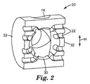
コネクタ10の内部には、ワイヤ(図示なし)が接続することができる接点12の一部が示されている。これらの部分は、絶縁体無剥離接続として形成することができる。図示されている実施形態において、隣接するガイド14を備えた3つの開口部16(そのうち1つは下側に形成されており、図1では見えない)を有するガイド部品20は、接点12の方向に動かすことができる。図2を参照して更に詳しく後述するように、複数のワイヤを有し、そのワイヤ全ての周りにシールド及び絶縁材を伴うケーブル1本が、図に示されているケーブルガイド14のうちいずれか1つに、それに対応する開口部16を介して挿入することができる。図示されている実施形態において、ガイド部品20は、平面上に形成されて個々のワイヤを収容するよう適合された凹部22(図2参照)と、曲面上に沿って3つの異なる位置に形成されたワイヤ開口部16とを備えた半円筒形タイプとして形成される。
A part of the
図1に示されているコネクタは、旋回可能なフラップ24の形態で2つの駆動部品を有し、このそれぞれが突出部26を有する。ケーブルがケーブルガイド14に挿入され、個々のワイヤが凹部22(図2参照)に収容されているとき、ガイド部品20は、接点12にごく近接して配置され、旋回可能なフラップをガイド部品20側に切り替えることができ、この旋回可能なフラップ24が図3に示す最終位置に近づくときに、突出部26がガイド部品20に噛み合って、接点12の方向に押し付けることができる。全体に、旋回可能なフラップ24は、ガイド部品20が移動する方向に対して垂直な軸を中心に旋回することができる。
The connector shown in FIG. 1 has two drive components in the form of
図1で分かるように、ケーブルガイド14は図1に見える半円筒の表面から図2に見えるガイド部品20の内部に向かってある程度の延長部分を有し得る。換言すれば、ガイド14は、実質的に円筒形の内壁を有することができ、これによりケーブルをガイドすることができる。更に、図1に示すガイド部品20は、(半円形の)側面、すなわち、旋回可能なフラップ24の側に向いている面、の一方又は両方に形成された開口部を追加的に有し得る。更に、旋回可能なフラップ24の一方又は両方が、上述の側面に開いたワイヤ開口部(図1には示されていない)へのアクセスを与えるため、適切な開口部を備えて形成され得る。この修正により、コネクタ10に接続されるケーブルは、図1に示されるように、背後側、上側及び下側からコネクタ10に達することができるだけでなく、側面の一方又は両方からも達することができる。
As can be seen in FIG. 1, the
図2は、接点12(図1参照)に面した側から見た図1のガイド部品20を示す。図2から分かるように、ケーブルガイド14はそれぞれ、ガイド部品20の内側で、ほぼ同じ位置で終わっている。その位置において、ケーブルの絶縁材及びシールドも通常、終了する。換言すれば、ケーブルのワイヤがコネクタ10の接点12と接続されるとき、ケーブルが適切なガイド14を通って挿入され、その絶縁材及びシールドが除去されて、ケーブルの端が、個々のワイヤが露出した状態になる。ケーブルは、図2に見られる凹部22内に個々のワイヤを収容することができるように配置することができる。このようにして、ケーブルの絶縁材及びシールドは、中央の開口部30の位置あたりで終了し、この箇所まで凹部22が延びている。
FIG. 2 shows the
図2に見られるように、図示されている実施形態において、凹部22はそれぞれ、開口部30から延在する第一部分を有し、これが開口部30からほぼ放射上に延びている。換言すれば、第一部分が一緒になって、幾分星形のような外観を有している。凹部22の第二部分は、互いにほぼ平行に延びている。図示されている実施形態において、開口部30の別の側にあるが、同じ高さ方向Hに沿ってほぼ同じ高さを有する、これらの凹部の第二部分は、互いに並んで整列され得る。しかしながら、凹部22は開口部30の片側だけに配置することもできる。ケーブルのワイヤが接点12に接続されるとき、個々のワイヤが互いに分離され、幾分星形のような、又は放射状に延びた外観に適応して、その個々のワイヤが凹部22に収容される。この場合において凹部22は、1つ以上の可撓性の部品、部分、及び/又はアダプタを有してもよく、さまざまな寸法のワイヤに対しそれらのサイズを概ね適合させることが留意される。例えば、1つ以上の凹部22は、タマネギ型の構造を有しかつ特定のワイヤを収容するのに十分な大きさの凹部にするのに必要な多数の「層」を除去するのに適している1つ以上の「ハーフパイプ」を有することができる。このような可撓性及び/又は除去可能な部品は、ゴムで製造することができる。さまざまな寸法のワイヤに対して凹部22を適合させる上述の方法は、例えば図4に示す凹部122のような、他のタイプの凹部にも適用することが可能であり、下記でより詳しく説明される。
As seen in FIG. 2, in the illustrated embodiment, each
凹部22の必要な部品を場合によって除去し、その中にワイヤを収容した後、図1を参照して上述したように、ガイド部品20は接点12の方向へ移動され、これにより各ワイヤが接触スリット(図1では見えない)に押し込まれる。凹部22に収容されたワイヤを接点12のスリットに押し込むのを可能にするため、ガイド部品20には、図2の観測者側を向いている表面に、接点12を収容するための複数のスロット(図示なし)を有する。このスロットは、凹部22と交差してもよい。別の実施形態において、ガイド部品20は、ガイド部品20の側面32に沿って揃えられた接点の間に収まるよう適合され、これにより凹部22に収容されたワイヤも、上述のように配置された接点に押し込まれる。
After optionally removing the necessary parts of the
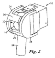
図3は、ケーブル34が接続された状態のコネクタを示す。図3に示す状況において、ケーブル34が下側から挿入されており、ガイド部品20が接点12(図1参照)の方へ移動しており、旋回可能なフラップ24が互いの方向に旋回して、それらの間にガイド部品20を挟んで包み込んでいる。この移動の際に、突出部26が、上記のようにガイド部品20を押し付ける役割を果たしている。図3から分かるように、本明細書に記述されているコネクタ10の多機能性は、ケーブル34は上から又は背面側からまっすぐに挿入することもできるという点で、有利であり得る。この点において、背面に露出しているワイヤ開口部16は、2つの突出部26の間に配置される。
FIG. 3 shows the connector with the
図4はガイド部品120の別の実施形態の透視図を示す。これは、図1及び3に示すコネクタに使用することができ、又は別の実施形態のコネクタに使用することもできる。ガイド部品120の全体的な外観は、図2に示すものとは異なり、全体の形状が立方体であり、延長部分140は、図2に示すガイド部品20の半円筒形で最も厚い部分に概ね対応している。図2のガイド部品20と同様、開口部116は3つの異なる方向に露出している。このように、正面側及び後側の、図4に見える開口部116も、図4の下側(図では見えない)に形成される。
FIG. 4 shows a perspective view of another embodiment of the
図4から分かるように、2つの開口部116.1及び116.2、並びに116.3及び116.4が、間にウェブ142を挟んで対になって形成されている。図示されている実施形態において、各開口部116は、例えば、4本のワイヤ(すなわちワイヤ2対)を収容するよう適合することができる。よって、8本のワイヤ(ワイヤ4対)のケーブル(図示なし)の絶縁材及びシールドが統合され、ウェブ142の位置で絶縁材及びシールドが終端し、ワイヤが開口部116を通って、例えば、各開口部を通ってワイヤ4本ずつ、挿入され得る。ガイド部品120の内部に延びるウェブ142のその部分(114として図示されている)は、ワイヤガイドとしての役目を果たすことができる。特に、反対側に形成されているワイヤガイド114.1及び114.2は、仕切り(図示なし)に延長することができ、及び/又はガイド部品120のある程度「内側」の位置、すなわち、ガイド部品120の中央方向に幾分ずれた位置で開始することができる。よって、左側と右側(図4での向きとして)のワイヤは、都合良く互いに分離され、ガイドされ得る。このような実施形態において、延長部分140の開口部(図示なし)に対して形成されているウェブ(図示なし)は、図4に見られるウェブ142と同一平面上にあり得る。
As can be seen from FIG. 4, two openings 116.1 and 116.2 and 116.3 and 116.4 are formed in pairs with the
図4の実施形態において、ワイヤを収容する4つの凹部122(下記で詳しく記述される)がそれぞれの側に形成される。更に、図示の実施形態は、第二凹部122.2と第三凹部122.3との間の、例えば両側面のほぼ中央に、ガイド部品120の内側に突出している内部突起144があり、これは、一方の側で、突起144の手前側の凹部に挿入されたワイヤを互いに分離する役目を果たし、もう一方の側で、突起144の向こう側にある凹部に挿入されたワイヤを互いに分離する役目を果たす。換言すれば、4本のワイヤを考えると、これは例えば手前左側の開口部116.1から挿入され、上側のワイヤ対に含まれる2本のワイヤが、例えば、凹部122.1及び122.2に挿入され得る。下側のワイヤ対に含まれるワイヤは、左側の突起144.1の下側の位置、凹部122.3及び122.4にあり、これらに挿入することができる。
In the embodiment of FIG. 4, four recesses 122 (described in detail below) for receiving wires are formed on each side. Furthermore, the illustrated embodiment has an
図4に見られるように、各凹部122には入口146があり、これは凹部122の他の部分よりも幾分狭くなっている。入口146は、その中に収容されるワイヤを固定するのにも用いることができる。これは、他の凹部122にも適用される。更に、凹部122は、絶縁材と合わせてほぼ円形の断面を有するワイヤを収容するため、同様にほぼ円形の断面を有してもよい。ワイヤが凹部122に挿入されたときに、その絶縁材は、一時的に圧縮され、これによりワイヤが狭い入口146を通り、ワイヤが凹部122に収容できるようにすることができる。図4の右側の凹部122に見られるように、凹部は全体に丸くなったV字形の凹部として、ガイド部品120内に向かって形成することができる。図示されている実施形態において、凹部122の外側領域の間に、狭い入口146、内側の全体にV字形の領域を有する凹部120、スロット148があり、これらは上述のように、ガイド部分120が接点方向に押し付けられているときに、接点12(図1参照)を収容し、ガイド部分120をガイドする役目を果たす。
As can be seen in FIG. 4, each recess 122 has an
本発明を実施形態を参照して説明してきた。前述の詳細な説明及び実施形態は理解を明確化するためにのみ提示した。詳細な説明及び実施形態から無用の限定はないと理解すべきである。例えば、側面及び方向に対する全ての参照は単なる例であり、特許請求の範囲に記載の本発明を限定するものではない。本発明の範囲から逸脱することなく、記載された実施形態に多くの変更を加えられることは、当業者には明らかである。したがって本発明の範囲は、本明細書に記載された正確な詳細及び構造に限定されるべきではなく、特許請求の範囲の文言による記載、及びそれらの構造と等価な物によって限定される。 The invention has been described with reference to embodiments. The foregoing detailed description and embodiments have been presented for clarity of understanding only. It should be understood that there is no unnecessary limitation from the detailed description and embodiments. For example, all references to sides and directions are merely examples and do not limit the invention as claimed. It will be apparent to those skilled in the art that many changes can be made in the embodiments described without departing from the scope of the invention. Accordingly, the scope of the invention should not be limited to the exact details and structures described herein, but should be limited by the wording of the claims and the equivalents thereof.
Claims (10)
ワイヤが前記コネクタ(10)内部で接続可能な複数の接点(12)と、
筐体(18)と、
少なくとも3つのワイヤ開口部(16、116)を有し、その各開口部(16、116)が、少なくとも2本のワイヤを収容するよう適合され、かつ前記接点の遠位側である前記コネクタ(10)の外側に露出している、少なくとも1つのガイド部品(20、120)と、
少なくとも3つの異なる方向に露出している前記ワイヤ開口部(16、116)と、を備える、電気通信技術におけるコネクタ。 A connector in telecommunications technology,
A plurality of contacts (12) to which wires can be connected within the connector (10);
A housing (18);
Said connector (16) having at least three wire openings (16, 116), each opening (16, 116) being adapted to receive at least two wires and being distal to said contacts ( 10) at least one guide part (20, 120) exposed outside;
Connector in telecommunications technology comprising at least three wire openings (16, 116) exposed in different directions.
Applications Claiming Priority (2)
| Application Number | Priority Date | Filing Date | Title |
|---|---|---|---|
| EP07019489A EP2045880B1 (en) | 2007-10-04 | 2007-10-04 | A connector in the field of telecommunications |
| PCT/US2008/078258 WO2009046000A2 (en) | 2007-10-04 | 2008-09-30 | A connector in the field of telecommunications |
Publications (2)
| Publication Number | Publication Date |
|---|---|
| JP2010541181A true JP2010541181A (en) | 2010-12-24 |
| JP2010541181A5 JP2010541181A5 (en) | 2011-10-20 |
Family
ID=39111317
Family Applications (1)
| Application Number | Title | Priority Date | Filing Date |
|---|---|---|---|
| JP2010528070A Pending JP2010541181A (en) | 2007-10-04 | 2008-09-30 | Connectors in telecommunications technology |
Country Status (14)
| Country | Link |
|---|---|
| US (1) | US7967642B2 (en) |
| EP (1) | EP2045880B1 (en) |
| JP (1) | JP2010541181A (en) |
| CN (1) | CN101821903B (en) |
| AR (1) | AR068717A1 (en) |
| AT (1) | ATE497270T1 (en) |
| BR (1) | BRPI0816509A2 (en) |
| DE (1) | DE602007012257D1 (en) |
| ES (1) | ES2360249T3 (en) |
| MX (1) | MX2010003190A (en) |
| PL (1) | PL2045880T3 (en) |
| RU (1) | RU2441302C2 (en) |
| TW (1) | TW200935684A (en) |
| WO (1) | WO2009046000A2 (en) |
Families Citing this family (9)
| Publication number | Priority date | Publication date | Assignee | Title |
|---|---|---|---|---|
| DE102011054563B3 (en) * | 2011-10-18 | 2013-01-24 | HARTING Electronics GmbH | Connectors |
| US8961217B2 (en) | 2013-03-12 | 2015-02-24 | Carlisle Interconnect Technologies, Inc. | Electrical connector assembly with integrated latching system, strain relief, and EMI shielding |
| TWM479548U (en) | 2014-01-08 | 2014-06-01 | Jyh Eng Technology Co Ltd | Multiple incoming lines connector |
| US9130283B1 (en) | 2014-02-18 | 2015-09-08 | Jyh Eng Technology Co., Ltd. | Electrical connector with multi-direction cable installation capability |
| US20170005444A1 (en) * | 2014-04-11 | 2017-01-05 | HARTING Electronics GmbH | Plug-in connector |
| US9147946B1 (en) * | 2014-05-30 | 2015-09-29 | Memie Mei Mei Wong | Electrical cable connector |
| CN106356690B (en) * | 2016-10-28 | 2024-02-06 | 上海天诚通信技术股份有限公司 | Crystal head swinging device |
| JP2019125528A (en) * | 2018-01-18 | 2019-07-25 | 株式会社オートネットワーク技術研究所 | Electric wire cover and connector |
| WO2022093227A1 (en) * | 2020-10-29 | 2022-05-05 | Hewlett-Packard Development Company, L. P. | Cable guides |
Citations (1)
| Publication number | Priority date | Publication date | Assignee | Title |
|---|---|---|---|---|
| JPH10241811A (en) * | 1997-02-24 | 1998-09-11 | Nitto Kogyo Co Ltd | Multipoint adapter for communication |
Family Cites Families (31)
| Publication number | Priority date | Publication date | Assignee | Title |
|---|---|---|---|---|
| US4140907A (en) * | 1976-07-29 | 1979-02-20 | Nippon Telegraph And Telephone Public Corporation | Thermal-plain paper recording system |
| US4236779A (en) * | 1978-05-01 | 1980-12-02 | Bunker Ramo Corporation | EMI Shielded cable and connector assembly |
| US4711507A (en) * | 1985-10-07 | 1987-12-08 | Thomas & Betts Corporation | Electrical connector and latching apparatus therefor |
| US5192226A (en) * | 1992-05-06 | 1993-03-09 | Wang Tsan Chi | Double-output port cable assembly for notebook computers |
| US5199904A (en) * | 1992-08-06 | 1993-04-06 | Safco Corporation | Electrical offset adapter plug |
| US5413493A (en) * | 1993-01-15 | 1995-05-09 | Hubbell Incorporated | Electrical connector assembly, especially for electric vehicle |
| FR2760136B1 (en) | 1997-02-27 | 1999-04-23 | Pouyet Sa | MODULAR JACK TYPE WALL SOCKET |
| FR2768862B1 (en) | 1997-09-22 | 1999-12-24 | Infra Sa | LOW POWER SOCKET WITH ORGANIZER REAR CAP |
| FR2769757B1 (en) | 1997-10-15 | 1999-12-10 | Pouyet Sa | AT LEAST PARTIALLY ARMORED WALL SOCKET, AND METHOD FOR CONNECTING AN ELECTRICAL CABLE TO SUCH A SOCKET |
| EP0935314B9 (en) | 1998-02-06 | 2011-05-11 | Fred Schmitt | Connector housing for 19 inch apparatus system |
| US6348035B1 (en) * | 1998-09-09 | 2002-02-19 | Asahi Kogaku Kogyo Kabushiki Kaisha | Connection system for electronic endoscope |
| US6160485A (en) * | 1998-12-29 | 2000-12-12 | Applied Systems Engineering, Llc | Voltage level conditioning transceiver cable |
| DE19959823C2 (en) | 1999-12-10 | 2003-04-30 | Krone Gmbh | Connection cable with electrical plug connection |
| DE10057869C1 (en) | 2000-11-21 | 2002-08-22 | Ria Btr Prod Gmbh | Connectors for shielded data and / or telecommunication cables |
| DE50211308D1 (en) * | 2001-08-20 | 2008-01-17 | Woertz Ag | Electrical terminal |
| DE10156251A1 (en) * | 2001-11-09 | 2003-05-22 | Ackermann Albert Gmbh Co | Electrical connector |
| US7035112B2 (en) * | 2002-07-08 | 2006-04-25 | Aten International Co., Ltd. | Automatic switch |
| US6830488B2 (en) | 2003-05-12 | 2004-12-14 | Krone, Inc. | Modular jack with wire management |
| US7150657B2 (en) * | 2003-05-23 | 2006-12-19 | Nordx/Cdt Inc. | Wire lead guide and method for terminating a communications cable |
| TWM250195U (en) * | 2003-07-21 | 2004-11-11 | Fullyear Brother Entpr Co Ltd | Adapting base structure of computer connector |
| US20060094281A1 (en) | 2004-11-04 | 2006-05-04 | Carlyle, Inc. | Latching electrical connector assembly |
| US7182647B2 (en) * | 2004-11-24 | 2007-02-27 | Cooper Technologies Company | Visible break assembly including a window to view a power connection |
| US7112086B1 (en) | 2005-04-08 | 2006-09-26 | Hon Hai Precision Ind. Co., Ltd. | Electrical cable assembly having cable guide |
| US7641610B2 (en) * | 2005-08-09 | 2010-01-05 | Olympus Medical Systems Corporation | Endoscope electric connection device |
| DE602005009179D1 (en) | 2005-08-12 | 2008-10-02 | 3M Innovative Properties Co | Telekommunikatiosverbinder |
| CN2854838Y (en) * | 2005-10-24 | 2007-01-03 | 3M创新有限公司 | Connection device for low tension circuit |
| US7572133B2 (en) * | 2005-11-14 | 2009-08-11 | Cooper Technologies Company | Separable loadbreak connector and system |
| GB0625061D0 (en) * | 2006-12-15 | 2007-01-24 | Tyco Electronics Amp Es Sa | A connector for use in terminating communications cables |
| US7497736B2 (en) * | 2006-12-19 | 2009-03-03 | Fci Americas Technology, Inc. | Shieldless, high-speed, low-cross-talk electrical connector |
| EP2115824B1 (en) * | 2007-02-23 | 2017-08-09 | FCI Asia Pte. Ltd. | Cable clamp |
| TWM320772U (en) * | 2007-03-21 | 2007-10-11 | Surtec Ind Inc | Signal communication socket with pierce terminal |
-
2007
- 2007-10-04 ES ES07019489T patent/ES2360249T3/en active Active
- 2007-10-04 EP EP07019489A patent/EP2045880B1/en not_active Not-in-force
- 2007-10-04 PL PL07019489T patent/PL2045880T3/en unknown
- 2007-10-04 DE DE602007012257T patent/DE602007012257D1/en active Active
- 2007-10-04 AT AT07019489T patent/ATE497270T1/en not_active IP Right Cessation
-
2008
- 2008-09-30 BR BRPI0816509-2A2A patent/BRPI0816509A2/en not_active Application Discontinuation
- 2008-09-30 WO PCT/US2008/078258 patent/WO2009046000A2/en active Application Filing
- 2008-09-30 JP JP2010528070A patent/JP2010541181A/en active Pending
- 2008-09-30 RU RU2010112251/07A patent/RU2441302C2/en active
- 2008-09-30 US US12/680,948 patent/US7967642B2/en not_active Expired - Fee Related
- 2008-09-30 CN CN2008801103597A patent/CN101821903B/en not_active Expired - Fee Related
- 2008-09-30 TW TW097137553A patent/TW200935684A/en unknown
- 2008-09-30 MX MX2010003190A patent/MX2010003190A/en active IP Right Grant
- 2008-10-02 AR ARP080104308A patent/AR068717A1/en unknown
Patent Citations (1)
| Publication number | Priority date | Publication date | Assignee | Title |
|---|---|---|---|---|
| JPH10241811A (en) * | 1997-02-24 | 1998-09-11 | Nitto Kogyo Co Ltd | Multipoint adapter for communication |
Also Published As
| Publication number | Publication date |
|---|---|
| ATE497270T1 (en) | 2011-02-15 |
| EP2045880B1 (en) | 2011-01-26 |
| ES2360249T3 (en) | 2011-06-02 |
| RU2441302C2 (en) | 2012-01-27 |
| RU2010112251A (en) | 2011-11-27 |
| EP2045880A1 (en) | 2009-04-08 |
| CN101821903A (en) | 2010-09-01 |
| MX2010003190A (en) | 2010-04-07 |
| BRPI0816509A2 (en) | 2015-02-24 |
| AR068717A1 (en) | 2009-12-02 |
| CN101821903B (en) | 2012-10-17 |
| DE602007012257D1 (en) | 2011-03-10 |
| PL2045880T3 (en) | 2011-06-30 |
| US20100273357A1 (en) | 2010-10-28 |
| TW200935684A (en) | 2009-08-16 |
| US7967642B2 (en) | 2011-06-28 |
| WO2009046000A3 (en) | 2009-06-04 |
| WO2009046000A2 (en) | 2009-04-09 |
Similar Documents
| Publication | Publication Date | Title |
|---|---|---|
| JP5124650B2 (en) | Shield attachable to connector in telecommunications field, combination of connector and at least one shield, and method of shielding the connector | |
| JP2010541181A (en) | Connectors in telecommunications technology | |
| US7857635B2 (en) | Board edge termination back-end connection assemblies and communications connectors including such assemblies | |
| US7503810B1 (en) | Board edge termination back-end connection assemblies and communications jacks including such assemblies | |
| EP2137794B1 (en) | Modular connector with reduced termination variability and improved performance | |
| EP1988611B1 (en) | Improvements in and relating to electrical connectors | |
| JP2022503638A (en) | Single-pair Ethernet connector that can be terminated in the field | |
| US11387606B2 (en) | Communication connectors utilizing multiple contact points | |
| JP6689956B2 (en) | Communication plug | |
| EP2128938A1 (en) | Jack Adapter in the Field of Telecommunication and Data Transmission | |
| JP6870065B2 (en) | RJ45 plug | |
| KR200311814Y1 (en) | T-type Extension jack | |
| WO2018039767A1 (en) | Electrical connector assembly |
Legal Events
| Date | Code | Title | Description |
|---|---|---|---|
| A521 | Written amendment |
Free format text: JAPANESE INTERMEDIATE CODE: A523 Effective date: 20110831 |
|
| A621 | Written request for application examination |
Free format text: JAPANESE INTERMEDIATE CODE: A621 Effective date: 20110831 |
|
| A131 | Notification of reasons for refusal |
Free format text: JAPANESE INTERMEDIATE CODE: A131 Effective date: 20121002 |
|
| A601 | Written request for extension of time |
Free format text: JAPANESE INTERMEDIATE CODE: A601 Effective date: 20130104 |
|
| A602 | Written permission of extension of time |
Free format text: JAPANESE INTERMEDIATE CODE: A602 Effective date: 20130111 |
|
| A02 | Decision of refusal |
Free format text: JAPANESE INTERMEDIATE CODE: A02 Effective date: 20130305 |