JP2010540102A - Blood pressure detection device - Google Patents
Blood pressure detection device Download PDFInfo
- Publication number
- JP2010540102A JP2010540102A JP2010527104A JP2010527104A JP2010540102A JP 2010540102 A JP2010540102 A JP 2010540102A JP 2010527104 A JP2010527104 A JP 2010527104A JP 2010527104 A JP2010527104 A JP 2010527104A JP 2010540102 A JP2010540102 A JP 2010540102A
- Authority
- JP
- Japan
- Prior art keywords
- deflection
- blood vessel
- vein
- sensor
- blood
- Prior art date
- Legal status (The legal status is an assumption and is not a legal conclusion. Google has not performed a legal analysis and makes no representation as to the accuracy of the status listed.)
- Granted
Links
Images






Classifications
-
- A—HUMAN NECESSITIES
- A61—MEDICAL OR VETERINARY SCIENCE; HYGIENE
- A61B—DIAGNOSIS; SURGERY; IDENTIFICATION
- A61B5/00—Measuring for diagnostic purposes; Identification of persons
- A61B5/02—Detecting, measuring or recording for evaluating the cardiovascular system, e.g. pulse, heart rate, blood pressure or blood flow
- A61B5/021—Measuring pressure in heart or blood vessels
- A61B5/0215—Measuring pressure in heart or blood vessels by means inserted into the body
-
- A—HUMAN NECESSITIES
- A61—MEDICAL OR VETERINARY SCIENCE; HYGIENE
- A61B—DIAGNOSIS; SURGERY; IDENTIFICATION
- A61B5/00—Measuring for diagnostic purposes; Identification of persons
- A61B5/02—Detecting, measuring or recording for evaluating the cardiovascular system, e.g. pulse, heart rate, blood pressure or blood flow
- A61B5/02028—Determining haemodynamic parameters not otherwise provided for, e.g. cardiac contractility or left ventricular ejection fraction
-
- A—HUMAN NECESSITIES
- A61—MEDICAL OR VETERINARY SCIENCE; HYGIENE
- A61B—DIAGNOSIS; SURGERY; IDENTIFICATION
- A61B5/00—Measuring for diagnostic purposes; Identification of persons
- A61B5/41—Detecting, measuring or recording for evaluating the immune or lymphatic systems
- A61B5/414—Evaluating particular organs or parts of the immune or lymphatic systems
- A61B5/418—Evaluating particular organs or parts of the immune or lymphatic systems lymph vessels, ducts or nodes
-
- A—HUMAN NECESSITIES
- A61—MEDICAL OR VETERINARY SCIENCE; HYGIENE
- A61N—ELECTROTHERAPY; MAGNETOTHERAPY; RADIATION THERAPY; ULTRASOUND THERAPY
- A61N1/00—Electrotherapy; Circuits therefor
- A61N1/18—Applying electric currents by contact electrodes
- A61N1/32—Applying electric currents by contact electrodes alternating or intermittent currents
- A61N1/36—Applying electric currents by contact electrodes alternating or intermittent currents for stimulation
- A61N1/362—Heart stimulators
- A61N1/365—Heart stimulators controlled by a physiological parameter, e.g. heart potential
- A61N1/36514—Heart stimulators controlled by a physiological parameter, e.g. heart potential controlled by a physiological quantity other than heart potential, e.g. blood pressure
Landscapes
- Health & Medical Sciences (AREA)
- Life Sciences & Earth Sciences (AREA)
- Cardiology (AREA)
- Biomedical Technology (AREA)
- Medical Informatics (AREA)
- Biophysics (AREA)
- Pathology (AREA)
- Engineering & Computer Science (AREA)
- Physiology (AREA)
- Heart & Thoracic Surgery (AREA)
- Physics & Mathematics (AREA)
- Molecular Biology (AREA)
- Surgery (AREA)
- Animal Behavior & Ethology (AREA)
- General Health & Medical Sciences (AREA)
- Public Health (AREA)
- Veterinary Medicine (AREA)
- Vascular Medicine (AREA)
- Measuring Pulse, Heart Rate, Blood Pressure Or Blood Flow (AREA)
Abstract
埋込経血管圧力検出装置としての血圧検出装置は、血管壁(272)偏向を示す偏向信号を出力するように構成される少なくとも1つの偏向センサ(224)と、偏向センサに取付けられた埋込センサ支持部材(222)とを有する。埋込センサ支持部材は、第1血管(201)に近接する第2血管(202)の一部において、偏向センサが第2血管の血管壁である第2血管壁(272)に接触することを促進するように構成される。第1血管の壁偏向が第2血管壁の一部を偏向させるように、第2血管壁の一部は、第1血管に隣接させられる。血管パラメータ測定方法は、静脈(202)内の偏向センサ(224)によって、静脈壁偏向を示す偏向信号を生成させることと、偏向信号を用いて、静脈に接触する血管である静脈接触血管(201)に関連するパラメータ値を測定することとを含む。 A blood pressure detection device as an implantable transvascular pressure detection device includes at least one deflection sensor (224) configured to output a deflection signal indicative of deflection of a blood vessel wall (272), and an implant attached to the deflection sensor. And a sensor support member (222). The implantable sensor support member is configured such that, in a part of the second blood vessel (202) adjacent to the first blood vessel (201), the deflection sensor contacts the second blood vessel wall (272) that is the blood vessel wall of the second blood vessel. Configured to promote. A portion of the second vessel wall is adjacent to the first vessel so that the wall deflection of the first vessel deflects a portion of the second vessel wall. In the blood vessel parameter measurement method, a deflection signal indicating venous wall deflection is generated by a deflection sensor (224) in a vein (202), and a vein contact blood vessel (201 that is a blood vessel contacting a vein using the deflection signal) (201). Measuring the parameter value associated with.
Description
本発明は、監視装置、治療装置、および治療方法に関し、より詳細には埋込装置を用いて血行動態パラメータを監視することに関する。 The present invention relates to monitoring devices, treatment devices, and methods of treatment, and more particularly to monitoring hemodynamic parameters using an implant device.
心臓は、正常に機能する場合、律動収縮を生じさせるとともに、全身に血液を送り込むことができる。心臓は、洞房(SA)結節によって始動される励起衝撃(すなわち脱分極)が、心筋全体にわたって迅速に実行できるようにする心房と心室の両方において、特殊伝導路を有する。これらの特殊伝導路は、洞房結節から心房心筋に、そして心房・心室結節に、および心室心筋に脱分極を行うことによって、両心房と両心室の協調収縮を生成させる。 When the heart functions normally, it can cause rhythmic contractions and pump blood throughout the body. The heart has a special conduction path in both the atria and the ventricle that allows the excitation shock (ie, depolarization) triggered by the sinoatrial (SA) node to be performed quickly throughout the myocardium. These special conduction pathways produce coordinated contraction of both atriums and both ventricles by depolarizing from the sinoatrial node to the atrial myocardium, to the atrial-ventricular node, and to the ventricular myocardium.
特殊伝導路は、それぞれ心腔の筋繊維の収縮を同期させ、且つそれぞれ心房または心室に対向する心房または心室の収縮を同期させる。特殊伝導路を正常に機能化させることによって生じる同期化が無いような場合、心臓のポンプ効率は大きく減少してしまう。これらの特殊伝導路の病変を示す患者は、心拍出量不全を被る虞がある。 Special conduction pathways synchronize the contraction of the muscle fibers of the heart chamber, respectively, and synchronize the contraction of the atrium or ventricle opposite the atrium or ventricle, respectively. In the absence of synchronization caused by normal functioning of the special conduction pathway, the heart's pumping efficiency is greatly reduced. Patients with these special conduction path lesions may suffer from cardiac output failure.
心房収縮と心室収縮の少なくとも一方の調律と協調を改善しようとして、一または複数の心腔にペーシング刺激を提供する心調律管理(CRM)装置が開発されてきた。心調律管理装置は通常、心臓由来の信号を検出するための回路と、電気刺激を心臓に提供するためのパルス発生器とを含む。患者の心腔内と心臓の静脈内の少なくとも一方に延びるリードは、心臓の電気信号を検出し、且つ不整脈および同調不全を治療する種々の治療に従って、刺激を心臓に送達する電極に連結される。 In an effort to improve rhythm and coordination of at least one of atrial and ventricular contractions, cardiac rhythm management (CRM) devices have been developed that provide pacing stimulation to one or more heart chambers. A cardiac rhythm management device typically includes circuitry for detecting heart-derived signals and a pulse generator for providing electrical stimulation to the heart. A lead extending into at least one of the patient's heart chamber and / or heart vein is coupled to an electrode that senses the heart's electrical signals and delivers stimuli to the heart in accordance with various therapies for treating arrhythmias and dyssynchrony. .
心調律管理は普通、心臓の状態を診断し、適切な治療を判定すべく、種々の心臓パラメータを検出する必要がある。現在使用されている多くの不整脈識別方法は、心電図(ECG)式技法に頼っている。 Cardiac rhythm management usually requires detecting various cardiac parameters to diagnose the condition of the heart and determine the appropriate treatment. Many arrhythmia identification methods currently in use rely on electrocardiogram (ECG) based techniques.
しかし、心電図信号を用いる心機能監視は、身体における他の電気信号(ノイズ)の存在や、治療中のブランキング時間を含む幾つかの因子に起因する間違いが生じ易い。しかも、検出した心電気信号は、実際の心拍出量を示さないこともあり得る。たとえば心電図手法は、細動状態を診断できるかもしれないが、細動中の実際の心拍出量を推定し難い虞
がある。
However, cardiac function monitoring using electrocardiogram signals is prone to error due to several factors including the presence of other electrical signals (noise) in the body and blanking time during treatment. Moreover, the detected cardiac electrical signal may not indicate the actual cardiac output. For example, the electrocardiogram technique may be able to diagnose the fibrillation state, but it may be difficult to estimate the actual cardiac output during fibrillation.
このように、埋込心臓装置に用いられる電気記録図式方法の有用性にもかかわらず、これらの方法は、間違いを起こし易くなり得る虞があるため、心拍出量を特性化する全ての状態において適切ではない。 Thus, in spite of the usefulness of the electrographic methods used in implantable heart devices, these methods can be prone to errors, so all states that characterize cardiac output Is not appropriate.
本発明は、経血管血行動態検出を実行する方法とシステムを提供し、さらに先行技術を超える種々の利点を提供する。
本発明は、経血管血行動態検出を実行する方法に関与する。本発明の一実施形態は、血管壁偏向を示す偏向信号を出力するように構成される少なくとも1つの偏向センサと、偏向センサに取付けられた埋込センサ支持部材とを含む埋込経血管圧力検出装置としての血圧検出装置を対象とする。前記センサ支持部材は、第1血管に近接する第2血管の一部で、偏向センサと第2血管壁間の接触を促進するように構成される。前記第2血管壁の一部は、第1血管の壁偏向が第2血管壁の一部を偏向させるように、第1血管に隣接する。
The present invention provides a method and system for performing transvascular hemodynamic detection, and further provides various advantages over the prior art.
The present invention relates to a method for performing transvascular hemodynamic detection. One embodiment of the present invention includes an implantable transvascular pressure detection that includes at least one deflection sensor configured to output a deflection signal indicative of vessel wall deflection and an implantable sensor support member attached to the deflection sensor. A blood pressure detection device as a device is targeted. The sensor support member is a portion of the second blood vessel proximate to the first blood vessel and is configured to facilitate contact between the deflection sensor and the second blood vessel wall. A portion of the second blood vessel wall is adjacent to the first blood vessel such that wall deflection of the first blood vessel deflects a portion of the second blood vessel wall.
経血管血行動態検出を実行する方法は、静脈内の偏向センサから、静脈の静脈壁偏向を示す偏向信号を発生させることと、偏向信号を用いて、静脈に接触する血管に関連するパラメータ値を測定することとを含むことが可能である。本発明の幾つかの実施形態において、パラメータ値は、心拍数である。 A method for performing transvascular hemodynamic detection includes generating a deflection signal indicating a vein wall deflection of a vein from a deflection sensor in a vein, and using the deflection signal, a parameter value related to a blood vessel contacting the vein is obtained. Measuring. In some embodiments of the invention, the parameter value is a heart rate.
経血管血行動態検出を実行する方法は更に、静脈内に位置するが偏向センサとは異なる基準センサから、静脈壁偏向を示す基準信号を発生させることと、偏向信号と基準信号を用いてパラメータ値を測定することとを含むことが可能である。本発明の幾つかの実施形態において、パラメータ値は、動脈血圧であることが可能である。 The method for performing transvascular hemodynamic detection further includes generating a reference signal indicative of venous wall deflection from a reference sensor located within the vein but different from the deflection sensor, and using the deflection signal and the reference signal as a parameter value Measuring. In some embodiments of the invention, the parameter value can be arterial blood pressure.
本発明の一実施形態は、静脈内のセンサから、静脈壁偏向を示す偏向信号を発生させる手段と、偏向信号を用いて、静脈に接触する血管に関連するパラメータ値を測定する手段とを含む。
上記の本発明の概要は、本発明のそれぞれ実施形態または全ての実施形態を記載することを目的とするに限らない。本発明のより完全な理解と共に、利点と功績は、以下の詳細な説明と特許請求の範囲を添付図面と併せて参照することによって、明らかになり、評価されることになる。
One embodiment of the invention includes means for generating a deflection signal indicative of vein wall deflection from an intravenous sensor, and means for using the deflection signal to measure a parameter value associated with a blood vessel contacting the vein. .
The above summary of the present invention is not intended to describe each embodiment or every implementation of the present invention. Advantages and benefits, together with a more complete understanding of the invention, will become apparent and appreciated by referring to the following detailed description and claims taken in conjunction with the accompanying drawings.
本発明は、種々の改変および別の形態をとり易いが、その詳細は、例として図面において示されており、以下で詳細に説明されることになる。しかし、当然のことながら、記載した特定の実施形態に本発明を限定することを目的としない。それどころか、本発明は、添付の特許請求の範囲によって規定されるように、本発明の範囲内にある全ての改変、等価物および選択肢を含めるものとする。 While the invention is amenable to various modifications and alternative forms, specifics thereof have been shown by way of example in the drawings and will be described in detail below. However, it should be understood that the invention is not intended to be limited to the specific embodiments described. On the contrary, the invention is intended to cover all modifications, equivalents, and alternatives falling within the scope of the invention as defined by the appended claims.
以下の例示実施形態の説明において、その部分を形成する添付図面と本発明を実践し得る種々の実施形態を参照する。図面は、例示のために示される。当然のことながら、本発明の範囲から逸脱しなければ、他の実施形態用い得るし、構造的および機能的変更を行い得る。 In the following description of exemplary embodiments, reference is made to the accompanying drawings that form a part hereof, and to various embodiments in which the invention may be practiced. The drawings are shown for illustrative purposes. Of course, other embodiments may be used and structural and functional changes may be made without departing from the scope of the invention.
本発明に従うシステム、装置、または方法は、本明細書において記載した一または複数の特徴、構造、方法、またはその組合せを含み得る。たとえば装置またはシステムは、以下に記載した一または複数の有益な特徴とプロセスの少なくとも一方を含めるべく実施され得る。そのような装置またはシステムは、本明細書において記載した特徴を全て含む必要はないが、有用な構造と機能性の少なくとも一方を提供する選択した形状構成を含むべ
く実施され得ることを目的とする。そのような装置またはシステムは、様々な治療的または診断的機能を提供すべく実施され得る。
A system, apparatus, or method according to the invention may include one or more features, structures, methods, or combinations thereof described herein. For example, an apparatus or system may be implemented to include at least one of one or more beneficial features and processes described below. It is intended that such an apparatus or system need not include all of the features described herein, but can be implemented to include selected features that provide useful structure and / or functionality. . Such a device or system can be implemented to provide a variety of therapeutic or diagnostic functions.
血圧、心拍数パラメータ、および他の血行動態パラメータを用いることによって、生理的状態を診断および監視でき、且つ治療を送達および評価するのに役立つことが可能である。たとえば速い心拍数は、頻脈性不整脈、一または複数の心腔の迅速かつ無秩序な収縮を特徴とする状態に関連する可能性がある。頻脈性不整脈は、細動、潜在的に致死性の心臓状態の前触れである虞がある。頻脈性不整脈と細動の両方に対して、埋込医療装置によって送達可能な電気刺激治療などの治療法が存在する。 By using blood pressure, heart rate parameters, and other hemodynamic parameters, physiological conditions can be diagnosed and monitored, and can be useful in delivering and evaluating therapy. For example, a fast heart rate may be associated with a condition characterized by tachyarrhythmia, rapid and disordered contraction of one or more heart chambers. Tachyarrhythmia can be a harbinger of fibrillation, a potentially fatal heart condition. There are therapies for both tachyarrhythmia and fibrillation, such as electrical stimulation therapy that can be delivered by an implantable medical device.
心臓状態を治療する治療法が存在するにもかかわらず、特定の心臓状態は、適切な治療を確実に送達するため、最初に正確に検出されるべきである。
心電気信号は、心臓の状態を診断および監視すべく、心拍数と他の心臓パラメータを測定するために広く用いられる。心電気信号は、表面電極または埋込信号を介して検出されることによって、心電図(ECG)または電気記録図(EGM)信号を生じさせ得る。しかし、心電図または電気記録図信号を用いて心電気信号を監視することは、幾つかの因子に起因する間違いが生じ易い。このような因子の1つは、たとえば骨格筋などの身体の非心筋が、心電図または電気記録図上にノイズとして出現する電気信号も生成させることである。また心信号を検出するブランキング時間が、電気療法の送達中および送達直後に存在する。何故なら、そうしないと電気刺激は、心電図または電気記録図上に大きな規模の信号として出現し得るため、より低い規模の心信号を分かり難くするからである。
Despite the existence of treatments that treat heart conditions, a particular heart condition should be detected accurately first to ensure delivery of the appropriate treatment.
Cardiac electrical signals are widely used to measure heart rate and other cardiac parameters to diagnose and monitor the condition of the heart. An electrocardiogram signal can be detected via a surface electrode or an implant signal to produce an electrocardiogram (ECG) or electrogram (EGM) signal. However, monitoring an electrocardiographic signal using an electrocardiogram or electrogram signal is prone to error due to several factors. One such factor is that non-myocardial bodies, such as skeletal muscles, also generate electrical signals that appear as noise on the electrocardiogram or electrogram. There is also a blanking time for detecting cardiac signals during and immediately after delivery of electrotherapy. This is because otherwise electrical stimulation can appear as a large-scale signal on the electrocardiogram or electrogram, making it difficult to understand lower-scale cardiac signals.
心電気活性の分析は、特に頻脈性不整脈および細動の状態において、並びに上記のように電気治療が送達される場合に、実際の心拍出量を測定する能力も制限される。従って埋込心臓装置において用いられる電気記録図式方法の有用性にもかかわらず、これらの方法は、間違いが起こり易くなり得るため、全ての状態には適さない。 Analysis of electrocardiographic activity is also limited in its ability to measure actual cardiac output, particularly in tachyarrhythmia and fibrillation conditions and when electrical therapy is delivered as described above. Thus, despite the usefulness of the electrographic methods used in implantable heart devices, these methods are not suitable for all situations because they can be prone to errors.
血行動態パラメータは、別に機械的に測定可能である。心臓は、血液を動脈系に吐出する。心臓腔、特に左心室の収縮は、動脈系を通って流れる血液に波を生成させることが可能である。多くの動脈は、心室収縮に関連する圧力の増加が動脈を周囲に広げ得るように、弾性特性を示す。従ってそれぞれ左心室収縮は、血液の波が動脈を移動する時、血圧の瞬時増加と動脈の膨張の少なくとも一方に関連可能である。 Hemodynamic parameters can be measured mechanically separately. The heart discharges blood into the arterial system. Contraction of the heart chamber, particularly the left ventricle, can generate waves in blood flowing through the arterial system. Many arteries exhibit elastic properties so that the increased pressure associated with ventricular contraction can spread the artery around. Thus, each left ventricular contraction can be associated with an instantaneous increase in blood pressure and / or dilatation of the artery as the blood wave moves through the artery.
心パルス、または心拍の存在は、患者の首を触診することと、患者の心臓から送り出される血液による患者の頸動脈の容積変化(物理的拡張と収縮)を検出することとによって予め検出されている。心臓の心室が心拍中に収縮するとき、圧力波が患者の末梢循環系中に送られる。動脈血圧は通常、心収縮期中の血液の心室駆出と共に上昇し、動脈系において連続する血圧波として出現する。動脈血圧は、大動脈からの血液で満たすべく心室が膨張すると(心拡張期)、再度低下する。 The presence of a heart pulse, or heartbeat, is detected in advance by palpating the patient's neck and detecting volume changes (physical dilation and contraction) in the patient's carotid artery due to blood pumped from the patient's heart. Yes. As the heart's ventricles contract during the heart beat, pressure waves are sent into the patient's peripheral circulatory system. Arterial blood pressure usually rises with ventricular ejection of blood during systole and appears as a continuous blood pressure wave in the arterial system. Arterial blood pressure decreases again when the ventricle expands (filled diastole) to fill with blood from the aorta.
収縮期血液パルスを検出すべく、首または手首に沿って手で皮膚を押し付けるなどの血行動態パラメータの伝統的外部測定は、皮膚および他の組織を介する検出に固有の間違いが生じ易い。さらにそのような血行動態パラメータの監視方法は、優れた監視と治療利便性、および自動性を提供する埋込監視装置および治療装置の分野において、実用的ではない。 Traditional external measurements of hemodynamic parameters, such as pressing the skin by hand along the neck or wrist to detect systolic blood pulses, are prone to errors inherent in detection through the skin and other tissues. Furthermore, such hemodynamic parameter monitoring methods are not practical in the field of implantable monitoring and treatment devices that provide superior monitoring and treatment convenience, and automation.
血圧と脈拍数を含む動脈における血行動態パラメータの監視は、特に重要になり得る。動脈血パラメータの機械的検出は、心電図/電気記録図式方法と比較して、ペーシングパルスおよび除細動パルスによる妨害を受け難く、たとえば血圧など、心電図/電気記録図式方法が不可能なパラメータを監視可能である。 Monitoring hemodynamic parameters in arteries, including blood pressure and pulse rate, can be particularly important. Mechanical detection of arterial blood parameters is less susceptible to pacing and defibrillation pulses compared to electrocardiogram / electrocardiographic methods and can monitor parameters that are not possible with electrocardiogram / electrogram methods, such as blood pressure It is.
血行動態パラメータの直接測定は、動脈内に配置した機械センサによって実行可能である。しかし、動脈内に配置したセンサによる血圧と動脈パルスの少なくとも一方の検出は、特定の問題を示す。たとえば動脈内の相対的に高い圧力と血流は、センサと支持部材の少なくとも一方上に血栓形成をもたらす虞がある。血栓症として公知の形成血栓は、遊離して塞栓として動脈内を漂う虞がある。塞栓は、動脈内に留まり、血流を制限する虞があるため、組織の損傷および潜在的には致死性の心臓麻痺と心臓発作のリスクを高める虞がある。 Direct measurement of hemodynamic parameters can be performed by mechanical sensors placed in the artery. However, the detection of at least one of blood pressure and arterial pulse by a sensor placed in the artery presents a particular problem. For example, relatively high pressure and blood flow in the artery can result in thrombus formation on at least one of the sensor and the support member. The formed thrombus, known as thrombosis, can be released and drift in the artery as an embolus. Emboli remain in the arteries and can limit blood flow, which can increase the risk of tissue damage and potentially fatal heart attack and heart attack.
静脈系の血行動態パラメータは、心臓状態を検出および診断するためには不適切であり得る。収縮期血液パルスは、動脈系と比較すると、静脈系においては測定することが劇的に少ない。従って動脈血圧の監視は、静脈圧の監視と比較して、心拍数、最大心駆出圧、拍出容量、および他の血行動態パラメータに関して、より多くの情報を提供可能である。 The venous hemodynamic parameters may be inadequate for detecting and diagnosing heart conditions. Systolic blood pulses are dramatically less measured in the venous system compared to the arterial system. Thus, arterial blood pressure monitoring can provide more information regarding heart rate, maximum cardiac ejection pressure, output volume, and other hemodynamic parameters compared to venous pressure monitoring.
本発明の装置は、動脈内には侵入しない、動脈血管パラメータの埋込検出を提供する。動脈の壁偏向は、動脈に隣接する血管を介して測定可能である。動脈壁偏向を用いることによって、収縮期血液パルスを検出し、且つ心拍出量と動脈血流の様々なパラメータを測定可能である。本発明の装置および方法は、動脈に隣接する血管の壁偏向を測定するため、血液パラメータ測定は、たとえば高圧動脈などの目的血管を侵襲的に妨害することなく、実行可能である。しかも本発明に従う測定は、心電図/電気記録図式方法を複雑にする電気的ノイズとブランキング時間の影響を受け難くし得、且つ心電図/電気記録図方法だけでは検出できないパラメータを監視する能力を提供し得る。 The device of the present invention provides for implant detection of arterial vascular parameters that do not enter the artery. Arterial wall deflection can be measured through a blood vessel adjacent to the artery. By using arterial wall deflection, systolic blood pulses can be detected and various parameters of cardiac output and arterial blood flow can be measured. Since the apparatus and method of the present invention measure the wall deflection of a blood vessel adjacent to an artery, blood parameter measurements can be performed without invasively interfering with a target vessel such as a high-pressure artery. Moreover, measurements according to the present invention are less susceptible to electrical noise and blanking time that complicate the electrocardiogram / electrogram method and provide the ability to monitor parameters that cannot be detected by the electrocardiogram / electrogram method alone. Can do.
様々な静脈および動脈を含む血管は、身体内で互いに隣接して位置することがよくある。互いに隣接する血管部分は、互いに平行または交差して走り得る。これらの近接血管は、一方の血管を通って進む比較的高圧の血液パルスが、血管の一部の周囲を一時的に偏向させ、隣接血管の壁に偏向を起こさせ得るように、互いに接触させることが可能である。血液パルスによって誘発される隣接血管壁の変位とパルス運動の少なくとも一方を検出することによって、目的血管には侵入せずに目的血管の血行動態を監視できるようになる。 Blood vessels, including various veins and arteries, are often located adjacent to each other in the body. Adjacent vessel portions can run parallel to or crossing each other. These adjacent blood vessels are brought into contact with each other so that a relatively high pressure blood pulse traveling through one blood vessel can temporarily deflect around a portion of the blood vessel and cause the walls of adjacent blood vessels to deflect. It is possible. By detecting at least one of the displacement of the adjacent blood vessel wall and the pulse motion induced by the blood pulse, the hemodynamics of the target blood vessel can be monitored without entering the target blood vessel.
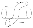
図1は、血管の交差を例示する。左冠状動脈回旋枝101(LCX)に交差する静脈102が例示される。標的血管つまり目的血管としての左冠状動脈回旋枝101(第1血管)は、心臓に近接して位置し、左心室から冠状動脈系に吐出された血液を受入れる。従って左冠状動脈回旋枝101は、収縮期血液パルスに対して感受性がある。それぞれ収縮期血液パルスは、左冠状動脈回旋枝101の壁を、周方向に拡張させることができる
静脈102(第2血管)は、左冠状動脈回旋枝101に近接する隣接血管である。静脈102が左冠状動脈回旋枝101に接触する場合、左冠状動脈回旋枝101の収縮期血液パルスが左冠状動脈回旋枝101を周方向に拡張させることによって、静脈102は、壁偏向し得る。
FIG. 1 illustrates vessel crossing. Illustrated is a
本発明の装置および方法で用いられ得る、多くの体血管の組合せが存在する。そのような血管の組合せには、限定するものではないが、大動脈に隣接する奇静脈、鎖骨下動脈に隣接する鎖骨下静脈、大動脈と腕頭動脈の少なくとも一方または右鎖骨下動脈に隣接する上大静脈、および頸動脈に隣接する内頸/外頸静脈、並びに一つの血管における血流動態が、隣接する血管において血管壁偏向を引起こす(たとえそのような血管壁偏向が、血管を付勢することによってのみ検出可能であっても)体内の任意の他の血管の組合せが包含される。 There are many combinations of body vessels that can be used in the devices and methods of the present invention. Such vascular combinations include, but are not limited to, the aortic vein adjacent to the aorta, the subclavian vein adjacent to the subclavian artery, at least one of the aorta and brachiocephalic artery or the upper adjacent to the right subclavian artery. Blood flow dynamics in the vena cava and the internal / external jugular veins adjacent to the carotid artery and in one vessel cause vessel wall deflection in the adjacent vessel (even if such vessel wall deflection energizes the vessel Any other combination of blood vessels in the body is encompassed (even if it can only be detected).
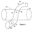
図2は、上記の左冠状動脈回旋枝101(第1血管)と静脈102(第2血管)の交差を示し得る血管交差を例示する。図1に関連して上方で検討した実施例を続けると、測定装置は、静脈202内に提供されている。測定装置は、偏向センサ224、偏向リング222、およびリード226を備える。任意に測定装置は、基準センサ225と基準リング221も含み得る。
FIG. 2 illustrates a blood vessel intersection that may indicate the intersection of the left coronary artery rotation branch 101 (first blood vessel) and the vein 102 (second blood vessel). Continuing with the example discussed above in connection with FIG. 1, a measuring device is provided in the
偏向センサ224と基準センサ225は、それぞれ偏向リング222と基準リング221に取付けられる。偏向リング222と基準リング221は、それぞれ偏向センサ224と基準センサ225の支持構造体として働き、偏向センサ224と基準センサ225を固定し、且つ静脈202の壁に接触させる。偏向リング222は、静脈202の径の拡張が静脈202と左冠状動脈回旋枝201の外壁面同士の間の自然離間距離を上回ることによって、静脈202の一部を直径方向に拡大させることによって、静脈202を左冠状動脈回旋枝201に接触させるのにも役立ち得る。
The
偏向センサ224は、静脈壁272の外面の一部が動脈壁271の外面の一部に接触する位置で、静脈壁272に固定される。偏向センサ224と基準センサ225は、偏向センサ224と基準センサ225がそれぞれ固定される静脈壁272の領域と領域付近の少なくとも一方で、静脈202の壁偏向を検出および測定可能である。左冠状動脈回旋枝201の収縮期血液パルスは、左冠状動脈回旋枝201内の圧力を一時的に増加させることによって、静脈壁272を付勢する。従って偏向センサ224は、左冠状動脈回旋枝201の収縮期血液パルスに起因する動脈壁271の偏向を、検出可能である。
The
それぞれ偏向センサ224と基準センサ225は、一または複数の信号を出力可能であり、前記信号は、リード226の一または複数の導体によって送達される。
幾つかの構成において、偏向センサ224によって検出される全ての静脈壁偏向が、左冠状動脈回旋枝201の収縮期血液パルスに起因することはないであろう。たとえば心臓、筋肉、他の体部の運動と患者の位置変化の少なくとも一方は、静脈壁偏向を引起こすことが可能である。基準センサ225は、左冠状動脈回旋枝201の収縮期血液パルスに起因する静脈壁偏向を除いて、偏向センサ224と同じ静脈壁偏向をおそらく検出し得るよ
うに、位置付けられる。それぞれ偏向センサ224と基準センサ225による信号出力を比較することによって、偏向センサ224によって検出される静脈壁偏向のうち、収縮期血液パルスに起因する静脈壁偏向と、何か他の因子に起因する静脈壁偏向とを判定可能である(そのうち収縮期血液パルスには起因しない静脈壁偏向は、おそらく偏向センサ224と基準センサ225の両センサによって検出され得る)。信号の比較は、血流事象と左冠状動脈回旋枝201のパラメータを同定すべく、一方の信号を他方の信号から差引くことと、他の方法間で検出した偏向事象の時期を相関させることとの少なくとも一方を含むことが可能である。
Each of
In some configurations, all venous wall deflection detected by the
種々の互いに異なる様式のセンサを用いることによって、壁偏向を検出可能である。たとえば静脈壁に固定される圧力変換器は、静脈壁偏向を検出可能である。静脈壁が偏向すると、静脈壁は、圧力変換器に力をかける。圧力変換器は、力に比例して、電圧を生成可能である。 By using various different types of sensors, wall deflection can be detected. For example, a pressure transducer fixed to the vein wall can detect the vein wall deflection. As the vein wall deflects, the vein wall exerts a force on the pressure transducer. The pressure transducer can generate a voltage in proportion to the force.
一または複数の歪ゲージを用いることによっても、壁偏向を測定可能である。静脈壁偏向が歪ゲージに衝突することによって歪ゲージを曲げるように、歪ゲージは位置付けられることが可能である。歪ゲージは、静脈壁の偏向が、静脈壁の大きさに変化をもたらせ、それによって歪ゲージを曲げるように、静脈壁に連結されることも可能である。 Wall deflection can also be measured by using one or more strain gauges. The strain gauge can be positioned so that the vein gauge deflects the strain gauge by impacting the strain gauge. The strain gauge can also be coupled to the vein wall such that the deflection of the vein wall can cause a change in the size of the vein wall, thereby bending the strain gauge.
圧力変換器と歪ゲージは、たとえば結晶などの圧電素子を含むことが可能である。圧電結晶は、偏向されると、力/偏向に比例して電圧(電気信号)を生成可能である。この電気信号の変化を測定することによって、センサ存在静脈(センサが存在する静脈)に隣接する血管の収縮期血液パルスと血圧のうちの、少なくとも一方を示すことが可能である。 The pressure transducer and strain gauge can include piezoelectric elements such as crystals. When the piezoelectric crystal is deflected, it can generate a voltage (electrical signal) in proportion to the force / deflection. By measuring this change in electrical signal, it is possible to indicate at least one of a systolic blood pulse and a blood pressure of a blood vessel adjacent to a sensor-existing vein (a vein in which the sensor exists).
圧電結晶を用いる圧力変換器と歪ゲージが、本明細書において検討した。更に、当該分野において公知の数あるセンサの中でも、容量性および抵抗性圧力変換器と歪ゲージを含む他の様式の圧力変換器および歪ゲージも考えられる。 Pressure transducers and strain gauges using piezoelectric crystals have been considered herein. In addition, other types of pressure transducers and strain gauges are contemplated, including capacitive and resistive pressure transducers and strain gauges, among other sensors known in the art.
血行動態パラメータを測定すべく、本発明の方法に従って光センサも使用可能である。たとえば光ファイバを通って進む光線路は、光ファイバが曲がると、変化可能である。これらの光線路の変化は、光ファイバの偏向を検出すべく、光センサによって検出可能である。光ファイバ偏向は、静脈壁の偏向に起因する。光ファイバの長さ方向に沿った特定の領域における偏向が、光ファイバの他の部分と比較して、光ファイバを通って進む光線路においてより劇的に変化を引起こすように、光ファイバは修正可能である。光ファイバの修正部分は、静脈壁の一部や、目的の血管に隣接する静脈壁の部分に沿って位置可能である。光ファイバの特に感受性が高い部分は、目的の血管内のパルスに起因して、静脈壁運動によって最も偏向され得る場所に位置するため、これらの事象は、光ファイバの他の部分の偏向とは区別可能である。 An optical sensor can also be used in accordance with the method of the present invention to measure hemodynamic parameters. For example, an optical line traveling through an optical fiber can change as the optical fiber bends. These changes in the optical line can be detected by an optical sensor to detect the deflection of the optical fiber. Optical fiber deflection results from vein wall deflection. An optical fiber is such that the deflection in a particular region along the length of the optical fiber causes a more dramatic change in the optical path traveling through the optical fiber compared to other parts of the optical fiber. It can be corrected. The modified portion of the optical fiber can be positioned along a portion of the vein wall or a portion of the vein wall adjacent to the target vessel. Because the particularly sensitive part of the optical fiber is located where it can be most deflected by venous wall motion due to pulses in the intended blood vessel, these events are not related to the deflection of other parts of the optical fiber. It can be distinguished.
静脈壁偏向を検出する本発明の装置と方法で使用され得る他のセンサには、限定されないが、数ある中でもインピーダンスセンサ、誘導センサ、抵抗センサ、容量センサ、一次元および多次元加速度計、容量流圧変換器、石英センサ、音響変換器、微電気機械システム(MEMS)、および超音波変換器が包含される。基準センサが用いられる実施形態において、基準センサは、偏向センサ(主要センサ)と同じ様式のセンサ、あるいは互いに異なる様式のセンサであり得る。 Other sensors that can be used in the apparatus and method of the present invention to detect venous wall deflection include, but are not limited to, impedance sensors, inductive sensors, resistance sensors, capacitive sensors, one-dimensional and multi-dimensional accelerometers, capacitive Fluid pressure transducers, quartz sensors, acoustic transducers, microelectromechanical systems (MEMS), and ultrasonic transducers are included. In embodiments in which a reference sensor is used, the reference sensor may be the same type of sensor as the deflection sensor (primary sensor) or a different type of sensor.
たとえばインピーダンスセンサを用いることによって、静脈内を流れる血液量を検出可能である。静脈壁偏向は、血液量に対応するインピーダンス測定値に、影響を及ぼす。
幾つかの実施形態において、加速度計を用いることによって、静脈壁偏向を検出可能である。たとえば加速度計の感受性軸が、血管壁の予測偏向軸に整列するような構造体によ
って、加速度計は固定可能である。この方向において加速度計は、静脈壁偏向の軸に沿う運動に対して感受性を有するが、静脈壁偏向の軸に沿わない他の動き(ノイズ)には、比較的感受性が無い。
For example, the amount of blood flowing in the vein can be detected by using an impedance sensor. Venous wall deflection affects impedance measurements corresponding to blood volume.
In some embodiments, the venous wall deflection can be detected by using an accelerometer. For example, the accelerometer can be fixed by a structure such that the sensitivity axis of the accelerometer is aligned with the predicted deflection axis of the vessel wall. In this direction, the accelerometer is sensitive to movement along the axis of venous wall deflection, but is relatively insensitive to other movements (noise) that are not along the axis of venous wall deflection.
静脈壁偏向を測定すべく用いられるセンサは、たとえば特別注文装置または既製装置のように構成され得る。検出性、耐久性、および生体適合性、あるいはその何れか一方を最適化すべく、センサは、格納、被覆、およびカプセル化、あるいはその何れか一方が行われることが可能である。 The sensor used to measure the venous wall deflection can be configured as a custom-made device or a ready-made device, for example. Sensors can be stored, covered, and / or encapsulated to optimize detectability, durability and / or biocompatibility.
動脈における全ての収縮期血液パルスが、センサによって検出できる隣接静脈の壁偏向を自然にもたらし得るわけではない。このような場合において、動脈が静脈に接触し、動脈の収縮期血液パルスが、静脈の検出性壁偏向をもたらし得るように、静脈と動脈の少なくとも一方を付勢する(バイアスを掛ける)ことが、センサ支持部材、または他の構造体にとって必要になり得る。実施形態によっては、センサ支持部材は、第2血管が第1血管に接触できるように、第2血管を付勢し得る。他の実施形態において、センサ支持部材は、第1血管の壁が偏向できるように、第2血管を付勢し得る。 Not every systolic blood pulse in an artery can naturally result in wall deflection of an adjacent vein that can be detected by a sensor. In such cases, the artery may contact the vein and bias (or bias) at least one of the vein and the artery so that the arterial systolic blood pulse can result in a detectable wall deflection of the vein. , Sensor support members, or other structures may be required. In some embodiments, the sensor support member may bias the second blood vessel so that the second blood vessel can contact the first blood vessel. In other embodiments, the sensor support member may bias the second blood vessel so that the wall of the first blood vessel can be deflected.
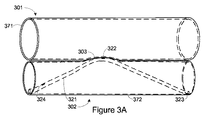
図3Aは、2つの平行血管で用いられる血液パラメータ検出装置を例示する。2つの平行血管は、標的血管つまり目的血管としての動脈301(第1血管)と、標的血管や目的血管に隣接する隣接血管としての静脈302(第2血管)である。リード321は、静脈302内に配置される。静脈302は、自然には動脈301に接触しない。しかし、リード321が静脈壁372の一部分を偏向させるように、リード321には、バイアスがかけられる。静脈壁偏向は、静脈壁372を動脈301に接触させ得、且つ動脈301の隆起303をもたらし得る。幾つかの状況において、静脈壁372の偏向が、動脈壁371の隆起303を生成する場合、より信頼性のあるセンサ情報と、より正確なセンサ情報とのうちの少なくとも一方が得られ得る。動脈301内で生じる収縮期血液パルスは、動脈壁371を偏向させることによって、静脈壁372を同様に偏向させ得る。静脈壁偏向は、偏向センサ322によって検出可能である。
FIG. 3A illustrates a blood parameter detection device used in two parallel blood vessels. The two parallel blood vessels are an artery 301 (first blood vessel) as a target blood vessel, that is, a target blood vessel, and a vein 302 (second blood vessel) as an adjacent blood vessel adjacent to the target blood vessel and the target blood vessel. The
リード321は、電極(図示略)を有することが可能であり、更に埋込医療装置(図示略)に連結され得る。リード321は、多数の導体を有することが可能であり、それぞれ偏向センサ322、第1基準センサ323、および第2基準センサ324に対して、一または複数の導体を含む。導体を用いることによって、偏向センサ322、第1基準センサ323、および第2基準センサ324への電力供給と、信号伝送の促進とのうちの少なくとも一方を行うことが可能である。
The
リード321は、静脈壁372が動脈301に接触することを維持するため、あるいは動脈301の隆起303を維持するために固定状態を保ち、且つ張力を維持すべく、機械的スプリング特性を発揮するように構成され得る。圧反射、生理学的変化、圧力変化、および他の因子は、動脈壁371への静脈壁372の接触を維持させるべく、リード321の緊張を必要とする可能性がある。金属、プラスチック、および他の材料の少なくとも一つを用いることによって、リード321に機械的スプリング特性を与え得る。たとえばNiTi合金(ニチノール)を用いることによって、リード321に曲げを与え得る。またリード321は、特定の患者の位置と適用の少なくとも一つに対して特別に構成できるようにすべく、ポーズエイブルであり得る。
The
リード321は、最適基準センサである第1基準センサ323と第2基準センサ324を有し得る。第1基準センサ323は、偏向センサ322と同様に、静脈壁372に接触するように位置付けられる。第1基準センサ323は、偏向センサ322とは異なり、動脈301の収縮期血液パルスに起因する壁偏向をおそらく検出しない。従って第1基準セ
ンサ323によって検出される静脈壁偏向事象は、動脈301の収縮期血液パルスに起因する静脈偏向を、他の条件に起因する静脈偏向から識別すべく用いることが可能である(他の条件に起因する静脈偏向は、おそらく第1基準センサ323と第2基準センサ324の両センサによって検出され得る)。
The
第2基準センサ324を用いることによって、静脈302の血圧を検出可能である。第1基準センサ323と第2基準センサ324によって生じる信号の比較を用いることによって、収縮期血液パルス事象と他の事象間を識別することと、静脈302と動脈301において検出される相対血圧に関する情報を提供することとの少なくとも一方を行うことが可能である。
By using the
図3Bは、二つの平行血管301,302を検証する血液パラメータ検出装置を例示する断面図である。2つの平行血管301,302は、図3Aにおいて例示される動脈301と静脈302であることが可能である。図3Bは、動脈301の隆起303を形成すべく静脈302にリード321を作用させる、リード321の付勢方法を例示する。偏向センサ322は、動脈301内の収縮期血液パルスに起因する、静脈壁偏向を検出すべく位置付けされる。任意の第1基準センサ323は、動脈301内の収縮期血液パルスには起因しない静脈壁偏向を検出すべく位置付けされる。任意の第2基準センサ324は、静脈302内の血圧を検出すべく位置付けされる。
FIG. 3B is a cross-sectional view illustrating a blood parameter detection device that verifies two
図4は、動脈401に対して垂直に延びる、静脈402内の血液パラメータ検出装置を例示する交差配置図である。静脈402と動脈401は、互いに自然には接触しないかもしれない。しかし、静脈402内のリード421は、静脈402が動脈401に接触するようにバイアスがかけられる。たとえば静脈402は、断面楕円形を呈し、且つ動脈401に作用を及ぼし得る。リード421にバイアスをかける1つの可能な効果的方法は、動脈401の壁に隆起403を形成することである。
FIG. 4 is a cross-sectional view illustrating a blood parameter detection device in the
動脈401内の収縮期血液パルスが、動脈壁471の偏向に対応する静脈壁472の偏向をもたらす場合に、動脈401と静脈402の接触点に近接する静脈壁472の部分に、偏向センサ422は位置付けされる。静脈壁472の偏向は、偏向センサ422によって検出可能である。静脈壁472の偏向の時期と大きさの少なくとも一方を用いることによって、数ある血行動態パラメータの中でも、心拍数と動脈401内の血圧を測定可能である。
When the systolic blood pulse in the
リード421は、任意の基準センサ423も含み得る。基準センサ423は、静脈壁472が動脈壁471に近接する領域において、位置付される。よって基準センサ423は、動脈401内で生じる事象にはおそらく起因し得ない静脈壁472偏向を検出すべく、位置付けされる。基準センサ423によって検出される圧力測定および壁偏向を用いることによって、静脈血圧を測定できる。更に、偏向センサ422によって検出されるノイズとの非関連性事象を相殺することによって、動脈血圧と心拍数を測定するのに役立つことが可能である。
Lead 421 may also include an
図5は、動脈501に平行な静脈502内の、血液パラメータ検出装置を例示する。静脈502と動脈501は、互いに自然には接触しないかもしれない。しかし本実施形態は、静脈502の一部分を、動脈501の一部分に接触させることができる。静脈502と動脈501の接触は、動脈501の隆起503をもたらし得る。静脈502は、静脈502内に位置する螺旋構造物521によって、動脈501に接触させられる。
FIG. 5 illustrates a blood parameter detection device in a
螺旋構造物521は、静脈502内壁に機械的に力を加え、それによって、螺旋構造物521の長さ方向に沿って静脈502を隆起させ得る。この機械的な力を提供するため、
螺旋構造物521が静脈502内に拘束される場合、機械的スプリング張力が得られる。従って血管サイズの微小変化(血管拡張反射、血圧増加に起因するか、他の何らかの機構に起因する変化)にもかかわらず、静脈壁572は、動脈壁571に接触し続けることになる。
The
When the
偏向センサ522は、螺旋構造物521に取付けられ、更に静脈壁偏向、特に動脈501内の収縮期血液パルスに起因する静脈壁偏向を検出すべく、位置付けされる。静脈502と動脈501の接触を強いる螺旋構造物521の機械的スプリング張力無しには、偏向センサ522は、収縮期血液パルスを含む動脈501で生じる事象を検出できないかもしれない。幾つかの実施形態において、螺旋構造物521の機械的スプリング張力が、動脈壁571の隆起503をもたらす場合、検出量は増強され得る。それ自体として、本明細書において開示される他の装置のように、偏向センサ522が動脈501と静脈502の接触点に近接する静脈壁偏向を検出することによって、動脈壁偏向、動脈圧、および動脈事象を検出できるように、螺旋構造物521は理想的に位置付けされる。
A
偏向センサ522は、動脈血行動態パラメータ情報を含む一または複数の信号を生成でき、且つたとえばリード526など、螺旋構造物521内か、螺旋構造物に取付けられる導体を用いて、信号を回路に送信可能である。またリード526の導体は、偏向センサ522と基準センサ523に電力を供給し得る。導体526はまた、電力供給および信号伝送を促進すべく、螺旋構造物521内に組込まれるか、螺旋構造物に取付けられ得る。
The
任意の基準センサ523は、螺旋構造物521と導体526を用いて、信号を生成および伝送することも可能である。基準センサ523は、圧力測定を行ない、且つ静脈壁偏向を検出すべく位置付けられる。基準センサ523を用いることによって、静脈血圧を測定でき、且つ偏向センサ522によって検出されるノイズとの非関連性事象を相殺することによって、動脈血圧および心拍数を測定するのに役立つことが可能である。
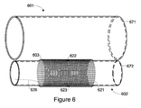
図6は、動脈601に平行な静脈602内の、血液パラメータ検出装置を例示する。静脈602と動脈601は、互いに自然には接触しないかもしれない。しかし本実施形態は、静脈602の一部分を、動脈601の一部分に接触させ、且つ動脈601の隆起603をもたらし得る。静脈602は、静脈602内に位置するステント621によって、動脈601との接触が生じる。
FIG. 6 illustrates a blood parameter detection device in a
ステント621は、静脈602内壁に機械的な力を加えることによって、ステント621の長さ方向に沿って静脈602を拡張させる。ステント621は、静脈602内に拘束されると、外側に一定周方向圧を加えることが可能である。従って血管サイズの微小変化にもかかわらず、静脈壁672は、動脈壁671に作用を及ぼし続けることになる。偏向センサ622と基準センサ623が、静脈または体運動、パルス、血流、およびそれ以外の、これら偏向センサ622と基準センサ623の静脈壁672への接触を緩めさせ得る他の因子にもかかわらず、これら偏向センサ622と基準センサ623が壁運動を検出する能力と、静脈壁672の検出能力との少なくとも一方を維持できるように、ステント621および他の要素は、偏向センサ622と基準センサ623を静脈壁672または静脈壁に近接させて固定する。
The
偏向センサ622と基準センサ623は、静脈壁圧力と偏向を検出することができ、更にリード626内の導体を用いて、圧力と偏向測定値の少なくとも一方に対応する信号を送信可能である。
The
リード626の導体は、偏向センサ622と基準センサ623に電力を供給し得る。導体626はまた、電力供給および信号伝送を促進すべく、ステント621内に組込まれる
か、ステントに取付けられ得る。
The conductor of
図5の螺旋構造物521と図6のステント621、および本明細書において開示される他の要素は、プラスチック、金属、および埋込みに適した任意の他の材料、あるいはその何れか一つから製造可能である。螺旋構造物521とステント621は、被覆されないか、ポリマと薬剤の少なくとも一方によって被覆されるニチノールまたはステンレス鋼であり得る。
The
血管内でのステント621の展開を促進する装置と方法は、当該分野において公知である。同様の装置と方法を用いることによって、螺旋構造物521、偏向リング222、基準リング221、または他の構造体を、血管内で展開することも可能である。
Devices and methods for promoting the deployment of
画像技法を用いることによって、本明細書において記載した装置および方法で用いられ得る隣接血管を同定でき、且つ静脈内のセンサが、隣接血管における血流事象に対応する静脈の壁偏向を検出できるように、血管内に構造体とセンサを配置するのに役立つことが可能である。 By using imaging techniques, adjacent blood vessels that can be used in the devices and methods described herein can be identified, and intravenous sensors can detect venous wall deflections corresponding to blood flow events in adjacent blood vessels. In addition, it can be useful to place structures and sensors within a blood vessel.
本発明の幾つかの実施形態において、音響検出と画像化の少なくとも一方の装置および技術を用いることによって、本明細書において参照される装置の埋込みによって標的血管と隣接血管の少なくとも一方において渦状血流が誘発されないように、確実に構成することが可能である。 In some embodiments of the present invention, by using at least one device and technique for acoustic detection and imaging, a spiral blood flow in at least one of the target vessel and the adjacent vessel by implantation of the device referred to herein. It is possible to make sure that it is not induced.
図7は、動脈701に隣接する静脈702内の、血行動態パラメータ検出装置を例示する。第1超音波変換器722と第2超音波変換器723は、静脈702の内壁にそれぞれ取付けられる。第1超音波変換器722と第2超音波変換器723は、弾性リング731によって支持される。第1超音波変換器722と第2超音波変換器723のうちの一方が他方に超音波パルスを送信することによって、第1超音波変換器722と第2超音波変換器723の間の距離を測定するように、第1超音波変換器722と第2超音波変換器723は構成可能である。第1超音波変換器722と第2超音波変換器723の間の距離を測定することによって、静脈702の大きさの変化を検出可能である。第1超音波変換器722と第2超音波変換器723によって検出される静脈の大きさの変化は、動脈701の収縮期血液パルスに関連可能である。動脈701の収縮期血液パルスは、動脈壁771の外面から静脈702の表面に力を加えることによって、静脈702壁の大きさを瞬時に変化させる。
FIG. 7 illustrates a hemodynamic parameter detection device in the
第1超音波変換器722と第2超音波変換器723は、それぞれ静脈702の血管壁に固定されるべく、バイアスがかけられ、縫合され、接着され、および血管壁内に組込まれ(たとえば組織カプセル化によって)、あるいはその何れか1つが行われることが可能である。
第1超音波変換器722と第2超音波変換器723は、静脈702の寸法変化を測定するため、信号強度、送受信パルスの時期、およびドップラーシフト効果の少なくとも一つを用い得る。
The first
第1超音波変換器722と第2超音波変換器723という2つの超音波変換器が図7において例示されるが、単一の超音波変換器を用いることも可能である。単一の超音波変換器は、超音波パルスを送信してからリターンエコーパルスを受信するまでの時間を、測定する。また音響変換器も、本明細書において検討した方法と装置で同様に用いられ得る。
Although two ultrasonic transducers, a first
図8は、治療装置800を例示する。図8に例示される治療装置800は、数ある中で
も徐脈、頻脈性不整脈、および細動などの医学的状態の検出および治療、並びに血行動態パラメータの監視ができる回路を用いる。治療装置800は、心調律管理装置(CRM装置)と、埋込ハウジング840内に封入した監視回路とを含む。監視回路は、ヘッダ850を介して治療装置800に接続される心臓内リードシステム830に、電気的連結される。
FIG. 8 illustrates a
図8には、心臓内電極を有する心臓内リードシステム830が例示され、他の種々の様式のリード/電極システムが、付加的または別に展開され得る。たとえばリード/電極システムは、心外膜リード/電極システムおよびたとえば心臓ショック、心外膜パッチなどの心臓と心血管系の少なくとも一方の外側にあるリードと電極、あるいはその何れか一方、および肋骨の外側ではないが、皮膚表面下に埋込んだ電極を備える皮下システムの少なくとも一つを含み得る。
FIG. 8 illustrates an
心臓内リードシステム830の一部は、患者の心臓内に挿入される。心臓内リードシステム830は、患者の心臓由来の電気信号を検出するためと、心臓に電気刺激を送達するためとの少なくとも一方のために、一または複数の心腔内、心腔上、または心腔周囲に位置付けられた心臓ペーシング/検出電極を含む。心臓内検出/ペーシング電極は、左心室、右心室、左心房、および右心房の少なくとも1つを含む一または複数の心腔の検出とペーシングの少なくとも一方を行うべく用いられ得る。心調律管理回路は、電極を介して送達される電気刺激パルスの送達を制御する。電気刺激パルスを用いることによって、血行動態的に十分な速度の心拍が、心拍の同期性を改善すべく用いられ得ること、心拍の強度を増加させるべく用いられ得ること、および規定治療と一致する心機能を支持すべく、他の治療目的に用いられ得ること、あるいはその何れか一方を保証し得る。
A portion of the
治療装置800の心臓内リードシステム830は、静脈802内に配置した第1心臓内リード831の一部を含む。静脈802と動脈801が互いに近接するように、静脈802は、左冠状動脈回旋枝冠状動脈801に交差する。第1心臓内リード831は、動脈801の収縮期血液パルスが動脈801壁に力を及ぼすことによって静脈802壁を偏向させるように、交差点で静脈802と動脈801の一部間の機械的接触を強いるべく、本明細書において検討した何れかの構造体を含み得る。
心臓内リードシステム830に取付けられる偏向センサ821は、動脈801の収縮期血液パルスに対応する静脈802壁偏向を検出するように構成される。偏向センサ821は、偏向情報を含有する一または複数の信号を、第1心臓内リード831を通じて、埋込ハウジング840の回路に伝送可能である。
A
第2心臓内リード832と心臓外リード833は、それぞれ単独で使用されるか、心臓内リードシステム830の他のリードと共に用いられ得る。第2心臓内リード832は、バイアス点822を含む。一または複数のセンサは、バイアス点822上とバイアス点822周囲の少なくとも一方に配置されることによって、圧力測定と血管壁偏向検出の少なくとも一方を行うことが可能である。バイアス点822は、本明細書において検討したように、隣接動脈の収縮期血液パルスに対応する静脈壁偏向の検出を促進可能である。
Second
心臓外リード833は、電極を含まないが、螺旋構造物823を含む。螺旋構造物823は、血管内で展開され得、且つ隣接血管の血行動態を監視すべくセンサで用いられることが可能である。例示されるように、心臓外リード833と螺旋構造物823は、心臓血管系には配置されないが、体内の他のどこかの血管で用いられることが可能である。たとえば螺旋構造物823は、患者の動脈に隣接する静脈の血行動態を監視すべく、頸静脈内に配置され得る。
通信回路は、心調律管理回路と、外部プログラマまたは先進患者管理(APM)システムなどの患者外部装置との間の通信を促進すべく、埋込ハウジング840内に配置される。また治療装置800は、血管壁偏向センサなどのセンサと、適切な回路とを含み得る。前記回路は、患者の代謝要求および血行動態を検出し、且つ検出した血行動態が患者の代謝要求に適しない場合には、患者の代謝要求に適合すべく心臓に送達されるペーシングパルスを調整する。
The communication circuit is disposed within the
幾つかの実施において、先進患者管理システムを用いることによって、数ある中でも信号処理、信号と検出血行動態事象の比較、データの貯蔵、および治療の指示を含む本明細書において検討した幾つかのプロセスを実行し得る。本明細書において記載した方法、構造体、および技法の少なくとも1つは、本明細書における特許文献1〜10のうちの一または複数において記載した特徴を含む種々の先進患者管理関連手法を組入れ得る。これらの治療手法と他の治療手法は、本明細書において検討した血流パラメータ測定値によって指示可能である。 In some implementations, by using an advanced patient management system, several processes discussed herein, including signal processing, comparison of signals and detected hemodynamic events, data storage, and treatment instructions, among others, Can be performed. At least one of the methods, structures, and techniques described herein may incorporate a variety of advanced patient management related techniques, including features described in one or more of US Pat. . These treatment techniques and other treatment techniques can be indicated by the blood flow parameter measurements discussed herein.
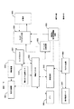
図9は、患者の種々の血行動態パラメータの監視を可能にすべく、血管壁偏向を検出するために組入れられるセンサを示す。心調律管理装置900は、ペーシングパルスを心臓に送達するペーシング治療回路930を含み得る。心調律管理装置900は、危険な頻脈性不整脈を終結させるべく、心臓に高エネルギー除細動または電気的除細動刺激を送達するように構成される除細動/電気的除細動回路935を含み得る。
FIG. 9 shows a sensor that is incorporated to detect vessel wall deflection to allow monitoring of various hemodynamic parameters of the patient. The cardiac
電気治療パルスは、患者の心臓内と体内の他のどこかの少なくとも一方の複数の位置に配置される複数の心電極905(電極の組合せ)を介して、送達可能である。電極905は、様々な電極905をセンサプロセッサ901と心調律管理装置900の他の要素の少なくとも一方に選択的に連結すべく用いられるスイッチマトリックス回路925に連結される。センサプロセッサ901はまた、本明細書において検討した何れかの偏向センサや基準センサまたは他のセンサであり得る一または複数のセンサ910に連結される。
The electrotherapy pulse can be delivered via a plurality of cardiac electrodes 905 (electrode combinations) placed at a plurality of locations in at least one of the patient's heart and elsewhere in the body. The
センサプロセッサ901は、心電極905とセンサ910を介して収集した情報を受信するように構成される。センサプロセッサ901は、電気記録図データを、たとえば心室収縮に対応する収縮期血液パルスなどの検出した血行動態事象と比較することなどの種々の機能を実行可能である。電気記録図データと検出血行動態データを比較することによって、電気記録図事象と検出血行動態事象の少なくとも一方を確認可能である。たとえば検出血管壁偏向を用いて測定した心拍数を使用することによって、電気記録図か心電図によって検出した心拍数を確認可能であり、その逆も同様である。電気記録図または心電図と血管壁偏向センサによって独立して測定した他のパラメータ値は、たとえば心電図または電気記録図から測定した心拍数値と、血管壁偏向センサによって測定した心拍数値とを平均化することなどのように、組合せることが可能である。
制御プロセッサ940は、心状態の診断と治療の指示の少なくとも一方を行うべく、センサ910から受信した血行動態パラメータ情報を用いることが可能である。
血管壁偏向に反応するパラメータ値は、たとえば動脈などの血管の血流状態を示すことが可能である。そのように動脈における血流を示すパラメータ値は、治療を開始または延期すべく回路によって用いられることが可能である。たとえば検出心電図信号が誤って、抗頻脈ペーシング(ATP)治療(通常、高エネルギーショック)の必要性を誤報しているような場合でも、本実施形態で測定したパラメータ値が動脈において十分な血流を示していれば、抗頻脈ペーシング治療を延期または遅延することができる。従って本発明は、不必要な抗頻脈ペーシング治療を、最小限に抑えることができる。そうしないと抗頻脈ペーシング治療は、患者にとって不快になり得、且つエネルギーを消費し得る。
The
The parameter value that reacts to the vascular wall deflection can indicate the blood flow state of a blood vessel such as an artery. Thus, parameter values indicative of blood flow in the artery can be used by the circuit to initiate or postpone therapy. For example, even if the detected electrocardiogram signal is erroneous and falsely reports the need for anti-tachycardia pacing (ATP) treatment (usually high energy shock), the parameter value measured in this embodiment has sufficient blood in the artery. If current is indicated, anti-tachycardia pacing therapy can be postponed or delayed. Thus, the present invention can minimize unnecessary anti-tachycardia pacing therapy. Otherwise, anti-tachycardia pacing therapy can be uncomfortable for the patient and can consume energy.
本明細書において検討したように、静脈壁偏向を用いて検出した徐脈、頻脈性不整脈、または細動状態は、ペーシング治療回路930または除細動/電気的除細動回路935および心電極905を用いて送達される電気刺激によって、治療され得る。これらの状態は、血管壁偏向に基づき本明細書において検討した血流パラメータを用いて、検出と確認の少なくとも一方が行われることが可能である。
As discussed herein, bradycardia, tachyarrhythmia, or fibrillation conditions detected using venous wall deflection may include pacing
心調律管理装置900のセンサと回路の少なくとも一方は、たとえば高域フィルタと低域フィルタの少なくとも一方などの信号調整回路を備え得る。たとえば帯域フィルタを用いることによって、心拍数に集中し得る(たとえば通過信号振動数は、標準的なヒトの心拍数範囲に対応する)。
At least one of the sensor and the circuit of the heart
薬貯蔵槽990に貯蔵され且つ薬送達機構980を用いて送達される種々の薬を用いて、生理学的状態を治療可能である。薬送達機構980は、数ある中でも弁、送風機、加圧、電気泳動、および音泳動を含む薬送達分野において公知の何れかの薬送達機構であり得る。主として、針または皮膚ポートを用いる薬の静脈内送達を採用する薬送達装置を含むように体外に位置する薬送達装置も、本発明の範囲内にあるものとする。
A variety of drugs stored in the
薬送達機構980は、静脈壁偏向検出方法と本明細書において開示した装置とを用いて検知した生理的状態の検出に反応して、一または複数の治療薬を送達可能である。たとえばセンサ910から一または複数の信号を受信したセンサプロセッサ901は、本明細書において開示した装置と方法を用いて、高血圧状態を検出し得る。高血圧診断(慢性か急性)に反応して、制御プロセッサ940は、高血圧状態を検討すべく、薬送達機構980に、治療薬を送達させるように指示可能である。治療薬は、限定するものではないが、ACE阻害剤、アンジオテンシンII受容体拮抗剤、α遮断薬、β遮断薬、カルシウムチャネル遮断薬および利尿剤、あるいはその何れか一つを包含可能である。
The
実施形態によっては、センサプロセッサ901は、本明細書において記載した静脈壁偏向方法に基づき、患者の状態を判定可能である。制御プロセッサ940は、患者の状態に関して、患者と医師、あるいはその何れか一方への通知を開始し得る。患者状態に変化が生じると、制御プロセッサ940は、携帯通信装置、プログラマ装置、および先進患者管理サーバの少なくとも一方を介して、患者と医師の少なくとも一方に送信し得る警報を出し始め得る。幾つかの実施形態において、制御プロセッサ940または先進患者管理サーバは、患者状態データを評価し、さらに、たとえば患者のペーシングパラメータまたは薬療法の変更などの患者治療法を修正するように、勧告し得る。
In some embodiments, the
センサプロセッサ901は、治療有効性を評価すべく、センサ901を用いて血行動態パラメータを監視し続けることが可能である。患者状態および治療有効性の変化に基づき、制御プロセッサ940は、薬送達機構980またはペーシング治療回路930に、薬治療とペーシング治療の少なくとも一方を自動的に修正するか、停止するように指示可能である。また、あるいは更に制御プロセッサ940は、患者の薬療法または他の規定の治療法の変更に関して勧告すべく、医師に通信可能である。このようにして、本発明の装置と方法は、閉ループ治療システムに関与可能である。
The
心調律管理装置900は通常、バッテリ電源(図示略)と、外部プログラマ装置960または他の患者外部装置に通信するための通信回路950とを含む。たとえばデータ、血行動態、およびプログラム命令、あるいはその何れか一つなどの情報および同類のものは、プログラマ装置960と患者管理サーバ970の間、心調律管理装置900とプログラマ装置960の間、および心調律管理装置900と患者管理サーバ970や他の外部システムの少なくとも一方との間、あるいはその何れか一方との間で転送可能である。実施形態によっては、センサプロセッサ901は、プログラマ装置960、患者管理サーバ97
0、または患者外部システムのうちの一構成要素であり得る。
The cardiac
0, or a component of a patient external system.
心調律管理装置900は、制御プロセッサ940によって、および制御プロセッサ940を通じて、アクセスしたプログラム命令とデータの少なくとも一方を保存するメモリ945も含む。様々な構成において、メモリ945は、血行動態に関する情報、血管壁偏向、パラメータ、測定値、プログラム命令、データ等を保存し得る。
The cardiac
図9において示される回路を用いることによって、本明細書において検討した種々の手法および技法を実行可能である。メモリ945は、たとえば制御プロセッサ940とセンサプロセッサ901の少なくとも一方などの回路によって実行されるべき、コンピュータプログラム、ソフトウエア、コンピュータ実行可能命令、コンピュータによって実行できる命令で符号化されるコンピュータ可読媒体等であることが可能である。たとえばメモリ945は、コンピュータプログラムを保存するコンピュータ可読媒体であることが可能である。前記コンピュータプログラムを制御プロセッサ940が実行することによって、公知であるか本開示物によって参照される種々の方法と技法に従って、センサ910からの一または複数の信号の受信、信号の測定、一または複数のアルゴリズムを用いる計算が生じ、更に、たとえば血圧または心拍数などのパラメータが出力される。同じように、本明細書において検討した他の方法と技法を、図9において示される回路を用いて行うことが可能である。
By using the circuit shown in FIG. 9, various techniques and techniques discussed herein can be implemented. The
図10のフローチャートは、隣接血管(たとえば静脈)から、目標血管(たとえば動脈)の血行動態を監視するプロセスを例示する。静脈壁偏向を示す偏向信号は、静脈内のセンサによって生成される(ステップS1010)。プロセスは、本明細書において開示される単独または組合せた何れかの偏向センサまたは血管偏向を検出できる他のセンサを用いることが可能である。 The flowchart of FIG. 10 illustrates the process of monitoring hemodynamics of a target vessel (eg, artery) from an adjacent vessel (eg, vein). A deflection signal indicating vein wall deflection is generated by a sensor in the vein (step S1010). The process can use any of the deflection sensors disclosed herein or any other sensor that can detect vascular deflection.
図10のプロセスは更に、偏向信号を用いて、静脈近接血管(静脈に近接する血管。たとえば動脈)に関連するパラメータ値を測定すること(ステップS1020)を含む。パラメータ値は、本明細書において開示される何れかのパラメータか、偏向信号を用いて測定され得る他のパラメータであり得る。血管は、動脈、リンパ管、静脈、または別の血管に隣接する身体の他の流体を運搬する血管であり得る。 The process of FIG. 10 further includes measuring a parameter value associated with the venous proximate blood vessel (a blood vessel proximate to the vein, eg, an artery) using the deflection signal (step S1020). The parameter value can be any parameter disclosed herein or other parameter that can be measured using a deflection signal. A blood vessel may be an artery, a lymph vessel, a vein, or a blood vessel that carries other fluids in the body adjacent to another blood vessel.
図11のフローチャートは、動脈に隣接する静脈から、動脈血圧を監視するプロセスを例示する。隣接動脈(静脈が隣接する動脈)の血圧を示す偏向信号は、静脈内の偏向センサによって生成される。偏向センサは、偏向センサが存在する静脈の壁の内面によって、偏向センサに加えられる力を測定することによって、隣接動脈の血圧を測定可能である。静脈壁の外面は、動脈壁の外面に接する。 The flowchart of FIG. 11 illustrates the process of monitoring arterial blood pressure from a vein adjacent to the artery. A deflection signal indicating the blood pressure of an adjacent artery (an artery to which a vein is adjacent) is generated by a deflection sensor in the vein. The deflection sensor can measure the blood pressure in the adjacent artery by measuring the force applied to the deflection sensor by the inner surface of the vein wall where the deflection sensor is present. The outer surface of the vein wall contacts the outer surface of the arterial wall.
図11のプロセスは更に、静脈内に位置するが偏向センサとは異なる基準センサから、基準信号を生成すること(ステップS1120)を含む。基準信号は、静脈内の血圧を示す。基準センサは、静脈壁に接する場合もあるし、静脈壁には接触しない場合もあり得る。 The process of FIG. 11 further includes generating a reference signal from a reference sensor located in the vein but different from the deflection sensor (step S1120). The reference signal indicates the blood pressure in the vein. The reference sensor may touch the vein wall or may not touch the vein wall.
図11のプロセスは更に、動脈血圧値を測定すべく、偏向信号の信号/ノイズ比を増加させるために基準信号を用いること(ステップS1130)を含む。たとえば幾つかの実施形態において、基準信号は、偏向信号から差引かれ得る。減算後の信号を用いることによって、動脈圧値を測定し得る。たとえば減算後の信号を、較正基準と比較することによって、動脈圧値を測定し得る。較正基準は、本明細書において開示される何れかの方法を用いて動脈血圧を測定し、更に多数の動脈血圧にわたって何度も、その値を公知の血圧(伝統的方法によって測定された)と比較することによって、本明細書において検討した何
れかの信号に対して測定され得る。これらの測定値から、信号と血圧の間の比例関係は、特定の信号値(たとえば電圧測定)が、血圧値(たとえばmmHg測定)に対応し得るように、確立可能である。同様に、特定信号(たとえば電圧測定)の特定変化は、血圧(mmHg測定)の変化に対応でき、且つ心拍数または心臓状態の変化に対応可能である。
The process of FIG. 11 further includes using the reference signal to increase the signal / noise ratio of the deflection signal to measure the arterial blood pressure value (step S1130). For example, in some embodiments, the reference signal can be subtracted from the deflection signal. By using the signal after the subtraction, the arterial pressure value can be measured. For example, the arterial pressure value may be measured by comparing the subtracted signal with a calibration standard. The calibration standard measures arterial blood pressure using any of the methods disclosed herein, and over and over again a number of arterial blood pressures with known blood pressure (measured by traditional methods). By comparison, it can be measured against any of the signals discussed herein. From these measurements, a proportional relationship between the signal and blood pressure can be established such that a particular signal value (eg, voltage measurement) can correspond to a blood pressure value (eg, mmHg measurement). Similarly, specific changes in specific signals (eg, voltage measurements) can correspond to changes in blood pressure (mmHg measurement) and can correspond to changes in heart rate or heart condition.
種々のアルゴリズムは、本明細書において検討した信号とパラメータに用いることが可能である。そのようなアルゴリズムには、限定しないが、平均化、アンサンブル平均化、パラメータ抽出、形態マッピング、dP/dt,Pk/Avg、概日周期同定、および可変遅延差分が包含される。たとえば圧変動の割合が評価され得、且つ同等の心臓dP/dt値にマッピング可能である。 Various algorithms can be used for the signals and parameters discussed herein. Such algorithms include, but are not limited to averaging, ensemble averaging, parameter extraction, form mapping, dP / dt, Pk / Avg, circadian period identification, and variable delay differences. For example, the rate of pressure fluctuation can be evaluated and can be mapped to an equivalent cardiac dP / dt value.
本明細書において示される要素、機能性、および構造配置は、埋込ペースメーカ/除細動器または他の埋込医療装置に組入れられ得る種々の特徴および特徴の組合せの理解を提供することを目的とする。当然ながら、様々な監視装置構成と治療装置構成の少なくとも一方は、比較的精緻な設計から、比較的簡素な設計まで考えられる。そのようなものとして、特定の装置構成は、本明細書において記載したような特定の特徴を含み得るが、他のそのような装置構成は、本明細書において記載した特定の特徴を除き得る。 The elements, functionality, and structural arrangements shown herein are intended to provide an understanding of the various features and combinations of features that can be incorporated into an implanted pacemaker / defibrillator or other implantable medical device. And Naturally, at least one of various monitoring device configurations and treatment device configurations can be considered from a relatively elaborate design to a relatively simple design. As such, certain device configurations may include certain features as described herein, but other such device configurations may exclude certain features described herein.
本発明の範囲から逸脱しなければ、本明細書の上記において検討した好適実施形態に種々の改変および付加を行うことが可能である。従って本発明の範囲は、上記の特定の実施形態によって限定されるべきではないが、以下に示す特許請求の範囲とその等価物によってのみ規定されるべきである。 Various modifications and additions can be made to the preferred embodiments discussed hereinabove without departing from the scope of the present invention. Accordingly, the scope of the invention should not be limited by the particular embodiments described above, but should be defined only by the claims that follow and their equivalents.
Claims (25)
前記偏向センサに取付けられる埋込センサ支持部材と
を備える埋込経血管圧力検出装置としての血圧検出装置であって、
第1血管に近接する第2血管の部分である血管近接部において、前記偏向センサが前記第2血管の血管壁である第2血管壁に接触することを、前記埋込センサ支持部材は促進させるように構成され、
その結果、前記第1血管の前記壁偏向が、前記第2血管の前記血管近接部を偏向させるように、前記血管近接部は前記第1血管に隣接させられる
ことを特徴とする、血圧検出装置。 A deflection sensor configured to output a deflection signal indicative of wall deflection that is deflection of the vessel wall;
A blood pressure detection device as an implantable transvascular pressure detection device comprising an implantation sensor support member attached to the deflection sensor,
The implantable sensor support member promotes that the deflection sensor contacts a second blood vessel wall that is a blood vessel wall of the second blood vessel in a blood vessel proximity portion that is a portion of the second blood vessel that is adjacent to the first blood vessel. Configured as
As a result, the blood vessel proximity portion is adjacent to the first blood vessel so that the wall deflection of the first blood vessel deflects the blood vessel proximity portion of the second blood vessel. .
請求項1記載の血圧検出装置。 The blood pressure detection device further comprises a pressure measurement circuit configured to measure the pressure in the first blood vessel based on the deflection signal indicative of the wall deflection of the second blood vessel.
The blood pressure detection device according to claim 1.
前記基準センサは、基準信号を出力するように構成され、
前記圧力測定回路は、前記偏向信号と前記基準信号を用いて、前記第1血管の圧力を測定するように構成される、
請求項1記載の血圧検出装置。 The blood pressure detection device further includes a reference sensor arranged in the second blood vessel and configured not to contact the blood vessel proximity portion of the second blood vessel,
The reference sensor is configured to output a reference signal;
The pressure measuring circuit is configured to measure the pressure of the first blood vessel using the deflection signal and the reference signal;
The blood pressure detection device according to claim 1.
請求項1記載の血圧検出装置。 The blood pressure detection device further comprises a heart rate measurement circuit configured to measure a heart rate based on the deflection signal,
The blood pressure detection device according to claim 1.
前記第2血管は、冠状静脈である、
請求項1記載の血圧検出装置。 The first blood vessel is a left coronary artery rotator;
The second blood vessel is a coronary vein;
The blood pressure detection device according to claim 1.
請求項1記載の血圧検出装置。 The implantable sensor support member comprises a stent;
The blood pressure detection device according to claim 1.
請求項1記載の血圧検出装置。 The embedded sensor support member has a coil.
The blood pressure detection device according to claim 1.
請求項1記載の血圧検出装置。 The embedded sensor support member has a helical structure;
The blood pressure detection device according to claim 1.
前記接触点は、前記偏向センサに近接する、
請求項1記載の血圧検出装置。 The implantable sensor support member is configured to promote contact of the second blood vessel with the first blood vessel and to maintain a contact point between the second blood vessel and the first blood vessel;
The contact point is proximate to the deflection sensor;
The blood pressure detection device according to claim 1.
請求項1記載の血圧検出装置。 The embedded sensor support member has a lead,
The blood pressure detection device according to claim 1.
請求項1記載の血圧検出装置。 The deflection sensor is an optical fiber sensor,
The blood pressure detection device according to claim 1.
請求項1記載の血圧検出装置。 The deflection sensor is an accelerometer;
The blood pressure detection device according to claim 1.
請求項1記載の血圧検出装置。 The deflection sensor is a pressure transducer;
The blood pressure detection device according to claim 1.
請求項1記載の血圧検出装置。 The deflection sensor is a strain gauge;
The blood pressure detection device according to claim 1.
請求項1記載の血圧検出装置。 The deflection sensor comprises an electrode configured to detect an impedance of the second blood vessel;
The blood pressure detection device according to claim 1.
前記偏向信号を用いて、前記静脈に接触する血管である静脈接触血管に関連するパラメータ値を測定することと
を備えることを特徴とする、血管パラメータ測定方法。 Generating a deflection signal indicative of the vein wall deflection of the vein by an intra-venous deflection sensor;
Measuring a parameter value related to a vein contact blood vessel, which is a blood vessel contacting the vein, using the deflection signal.
請求項16記載の血管パラメータ測定方法。 The parameter is pressure;
The blood vessel parameter measurement method according to claim 16.
前記静脈内に位置するが、前記偏向センサとは異なる基準センサによって、前記静脈壁偏向を示す基準信号を生成することと;
前記偏向信号と前記基準信号を用いて、前記パラメータ値を測定することと
を備える、
請求項16記載の血管パラメータ測定方法。 The blood vessel parameter measurement method further includes:
Generating a reference signal indicative of the vein wall deflection by a reference sensor located within the vein but different from the deflection sensor;
Measuring the parameter value using the deflection signal and the reference signal,
The blood vessel parameter measurement method according to claim 16.
請求項16記載の血管パラメータ測定方法。 The venous contact blood vessel is an artery;
The blood vessel parameter measurement method according to claim 16.
前記静脈は、冠状静脈である、
請求項16記載の血管パラメータ測定方法。 The venous contact blood vessel is the left coronary artery circumflex;
The vein is a coronary vein;
The blood vessel parameter measurement method according to claim 16.
請求項16記載の血管パラメータ測定方法。 The vascular parameter measurement method further supports the deflection sensor within the vein using one or more stents, a helical structure, and an annular support member to maintain the deflection sensor in contact with the vein wall. So that the venous wall is brought into contact with the venous contact vessel wall,
The blood vessel parameter measurement method according to claim 16.
前記静脈の外面が前記偏向センサに近接する接触点において、前記静脈が前記静脈接触血管の外面に接触することを維持すべく、前記静脈付勢構造体は前記静脈を付勢するように配置される、
請求項16記載の血管パラメータ測定方法。 The vascular parameter measurement method further includes disposing a vein biasing structure in the vein,
The vein biasing structure is arranged to bias the vein so as to maintain the vein in contact with the outer surface of the vein contact vessel at a contact point where the outer surface of the vein is in proximity to the deflection sensor. The
The blood vessel parameter measurement method according to claim 16.
請求項16記載の血管パラメータ測定方法。 The vascular parameter measurement method further includes extending an anti-tachyarrhythmia pacing interval based on the parameter indicating a blood flow state of the venous contact blood vessel.
The blood vessel parameter measurement method according to claim 16.
前記偏向信号を用いて、前記静脈に接する血管である静脈接触血管に関連するパラメータ値を測定するパラメータ値測定手段と
を備えることを特徴とする、血管パラメータ測定システム。 Deflection signal generating means for generating a deflection signal indicative of vein wall deflection by a deflection sensor in the vein;
A blood vessel parameter measurement system comprising parameter value measurement means for measuring a parameter value related to a vein contact blood vessel that is a blood vessel in contact with the vein using the deflection signal.
前記静脈内に位置するが、前記偏向センサとは異なる基準センサによって、前記静脈壁偏向を示す基準信号を生成する基準信号生成手段を備え、
前記パラメータ値測定手段は、前記偏向信号と前記基準信号を用いて、前記パラメータ値を測定する、
請求項24記載の血管パラメータ測定システム。 The blood vessel parameter measurement system further includes:
Reference signal generating means for generating a reference signal indicating the vein wall deflection by a reference sensor that is located in the vein but different from the deflection sensor,
The parameter value measuring means measures the parameter value using the deflection signal and the reference signal.
The blood vessel parameter measurement system according to claim 24.
Applications Claiming Priority (3)
| Application Number | Priority Date | Filing Date | Title |
|---|---|---|---|
| US11/904,946 US20090088651A1 (en) | 2007-09-28 | 2007-09-28 | Method and apparatus to perform transvascular hemodynamic sensing |
| US11/904,946 | 2007-09-28 | ||
| PCT/US2008/077492 WO2009045811A1 (en) | 2007-09-28 | 2008-09-24 | Method and apparatus to perform transvascular hemodynamic sensing |
Publications (2)
| Publication Number | Publication Date |
|---|---|
| JP2010540102A true JP2010540102A (en) | 2010-12-24 |
| JP5043193B2 JP5043193B2 (en) | 2012-10-10 |
Family
ID=40125013
Family Applications (1)
| Application Number | Title | Priority Date | Filing Date |
|---|---|---|---|
| JP2010527104A Expired - Fee Related JP5043193B2 (en) | 2007-09-28 | 2008-09-24 | Blood pressure detection device |
Country Status (4)
| Country | Link |
|---|---|
| US (1) | US20090088651A1 (en) |
| EP (1) | EP2211699A1 (en) |
| JP (1) | JP5043193B2 (en) |
| WO (1) | WO2009045811A1 (en) |
Families Citing this family (8)
| Publication number | Priority date | Publication date | Assignee | Title |
|---|---|---|---|---|
| US8109879B2 (en) | 2006-01-10 | 2012-02-07 | Cardiac Pacemakers, Inc. | Assessing autonomic activity using baroreflex analysis |
| WO2009009131A2 (en) | 2007-07-11 | 2009-01-15 | California Institute Of Technology | Cardiac assist system using helical arrangement of contractile bands and helically-twisting cardiac assist device |
| US8147415B2 (en) | 2008-05-07 | 2012-04-03 | Cardiac Pacemakers, Inc. | System and method for detection of pulmonary embolism |
| US9125655B2 (en) * | 2010-07-16 | 2015-09-08 | California Institute Of Technology | Correction and optimization of wave reflection in blood vessels |
| US20160287181A1 (en) * | 2013-12-05 | 2016-10-06 | Apple Inc. | Wearable multi-modal physiological sensing system |
| WO2016012882A2 (en) | 2014-07-24 | 2016-01-28 | Cochlear Limited | Implanted medical devices having electrode assemblies |
| WO2017037613A1 (en) | 2015-08-28 | 2017-03-09 | Cochlear Limited | Implantable stimulating assembly |
| EP3723586B1 (en) * | 2017-12-15 | 2021-04-14 | Koninklijke Philips N.V. | Implant device for in-body monitoring |
Family Cites Families (19)
| Publication number | Priority date | Publication date | Assignee | Title |
|---|---|---|---|---|
| US5409009A (en) * | 1994-03-18 | 1995-04-25 | Medtronic, Inc. | Methods for measurement of arterial blood flow |
| US5995860A (en) * | 1995-07-06 | 1999-11-30 | Thomas Jefferson University | Implantable sensor and system for measurement and control of blood constituent levels |
| US6129675A (en) * | 1998-09-11 | 2000-10-10 | Jay; Gregory D. | Device and method for measuring pulsus paradoxus |
| US7313444B2 (en) * | 1998-11-20 | 2007-12-25 | Pacesetter, Inc. | Self-anchoring coronary sinus lead |
| US6077227A (en) * | 1998-12-28 | 2000-06-20 | Medtronic, Inc. | Method for manufacture and implant of an implantable blood vessel cuff |
| US6312378B1 (en) * | 1999-06-03 | 2001-11-06 | Cardiac Intelligence Corporation | System and method for automated collection and analysis of patient information retrieved from an implantable medical device for remote patient care |
| US6270457B1 (en) * | 1999-06-03 | 2001-08-07 | Cardiac Intelligence Corp. | System and method for automated collection and analysis of regularly retrieved patient information for remote patient care |
| US6221011B1 (en) * | 1999-07-26 | 2001-04-24 | Cardiac Intelligence Corporation | System and method for determining a reference baseline of individual patient status for use in an automated collection and analysis patient care system |
| US6440066B1 (en) * | 1999-11-16 | 2002-08-27 | Cardiac Intelligence Corporation | Automated collection and analysis patient care system and method for ordering and prioritizing multiple health disorders to identify an index disorder |
| US6368284B1 (en) * | 1999-11-16 | 2002-04-09 | Cardiac Intelligence Corporation | Automated collection and analysis patient care system and method for diagnosing and monitoring myocardial ischemia and outcomes thereof |
| US6336903B1 (en) * | 1999-11-16 | 2002-01-08 | Cardiac Intelligence Corp. | Automated collection and analysis patient care system and method for diagnosing and monitoring congestive heart failure and outcomes thereof |
| US6398728B1 (en) * | 1999-11-16 | 2002-06-04 | Cardiac Intelligence Corporation | Automated collection and analysis patient care system and method for diagnosing and monitoring respiratory insufficiency and outcomes thereof |
| US6824521B2 (en) * | 2001-01-22 | 2004-11-30 | Integrated Sensing Systems, Inc. | Sensing catheter system and method of fabrication |
| US6514214B2 (en) * | 2001-02-13 | 2003-02-04 | Scimed Life Systems, Inc. | Intravascular temperature sensor |
| US7155284B1 (en) * | 2002-01-24 | 2006-12-26 | Advanced Bionics Corporation | Treatment of hypertension |
| TW570769B (en) * | 2002-04-26 | 2004-01-11 | Chin-Yu Lin | Method and device for measuring pulse signals for simultaneously obtaining pulse pressure and blood flow rate |
| US20060122522A1 (en) * | 2004-12-03 | 2006-06-08 | Abhi Chavan | Devices and methods for positioning and anchoring implantable sensor devices |
| US20070088214A1 (en) * | 2005-10-14 | 2007-04-19 | Cardiac Pacemakers Inc. | Implantable physiologic monitoring system |
| US8109879B2 (en) * | 2006-01-10 | 2012-02-07 | Cardiac Pacemakers, Inc. | Assessing autonomic activity using baroreflex analysis |
-
2007
- 2007-09-28 US US11/904,946 patent/US20090088651A1/en not_active Abandoned
-
2008
- 2008-09-24 EP EP08835713A patent/EP2211699A1/en not_active Withdrawn
- 2008-09-24 JP JP2010527104A patent/JP5043193B2/en not_active Expired - Fee Related
- 2008-09-24 WO PCT/US2008/077492 patent/WO2009045811A1/en not_active Ceased
Also Published As
| Publication number | Publication date |
|---|---|
| JP5043193B2 (en) | 2012-10-10 |
| US20090088651A1 (en) | 2009-04-02 |
| WO2009045811A1 (en) | 2009-04-09 |
| EP2211699A1 (en) | 2010-08-04 |
Similar Documents
| Publication | Publication Date | Title |
|---|---|---|
| US5409009A (en) | Methods for measurement of arterial blood flow | |
| EP3487579B1 (en) | System for utilizing an atrial contraction timing fiducial in a leadless cardiac pacemaker system | |
| US10874860B2 (en) | Method and system for determining a cardiac cycle pace time in accordance with metabolic demand in a leadless cardiac pacemaker system | |
| US7409244B2 (en) | Method and apparatus for adjusting interventricular delay based on ventricular pressure | |
| US11147965B2 (en) | Method and system for determining pace timing in a leadless cardiac pacemaker system | |
| US9675315B2 (en) | Method and apparatus for cardiac function monitoring | |
| US7181268B2 (en) | Ischemia detection | |
| JP5043193B2 (en) | Blood pressure detection device | |
| EP1690566B1 (en) | Ischemia detector | |
| CN106456023B (en) | Method and apparatus for detecting atrial tachyarrhythmia using heart sounds | |
| EP1423163B1 (en) | System for detecting myocardial ischemia | |
| US20150051467A1 (en) | Implantable device and method for monitoring venous diameter | |
| US20070161912A1 (en) | Assessing autonomic activity using baroreflex analysis | |
| JP5178815B2 (en) | Closed-loop resynchronization treatment of dyssynchrony | |
| US8818507B2 (en) | Coronary vein dimensional sensor and fixation apparatus | |
| WO2010059291A1 (en) | Assessment of pulmonary vascular resistance via pulmonary artery pressure | |
| US20180117340A1 (en) | Implantable medical device with gyroscope | |
| US20100305649A1 (en) | System and method for decompensation detection and treatment based on patient hemodynamics | |
| EP2491977B1 (en) | System for adapting pacing settings of a cardiac stimulator |
Legal Events
| Date | Code | Title | Description |
|---|---|---|---|
| RD04 | Notification of resignation of power of attorney |
Free format text: JAPANESE INTERMEDIATE CODE: A7424 Effective date: 20120210 |
|
| A977 | Report on retrieval |
Free format text: JAPANESE INTERMEDIATE CODE: A971007 Effective date: 20120330 |
|
| TRDD | Decision of grant or rejection written | ||
| A01 | Written decision to grant a patent or to grant a registration (utility model) |
Free format text: JAPANESE INTERMEDIATE CODE: A01 Effective date: 20120626 |
|
| A01 | Written decision to grant a patent or to grant a registration (utility model) |
Free format text: JAPANESE INTERMEDIATE CODE: A01 |
|
| A61 | First payment of annual fees (during grant procedure) |
Free format text: JAPANESE INTERMEDIATE CODE: A61 Effective date: 20120711 |
|
| R150 | Certificate of patent or registration of utility model |
Free format text: JAPANESE INTERMEDIATE CODE: R150 |
|
| FPAY | Renewal fee payment (event date is renewal date of database) |
Free format text: PAYMENT UNTIL: 20150720 Year of fee payment: 3 |
|
| LAPS | Cancellation because of no payment of annual fees |