JP2010539414A - Compound gear - Google Patents
Compound gear Download PDFInfo
- Publication number
- JP2010539414A JP2010539414A JP2010524974A JP2010524974A JP2010539414A JP 2010539414 A JP2010539414 A JP 2010539414A JP 2010524974 A JP2010524974 A JP 2010524974A JP 2010524974 A JP2010524974 A JP 2010524974A JP 2010539414 A JP2010539414 A JP 2010539414A
- Authority
- JP
- Japan
- Prior art keywords
- skin
- core
- gear
- thickness
- tooth
- Prior art date
- Legal status (The legal status is an assumption and is not a legal conclusion. Google has not performed a legal analysis and makes no representation as to the accuracy of the status listed.)
- Pending
Links
Images

Classifications
-
- F—MECHANICAL ENGINEERING; LIGHTING; HEATING; WEAPONS; BLASTING
- F16—ENGINEERING ELEMENTS AND UNITS; GENERAL MEASURES FOR PRODUCING AND MAINTAINING EFFECTIVE FUNCTIONING OF MACHINES OR INSTALLATIONS; THERMAL INSULATION IN GENERAL
- F16H—GEARING
- F16H55/00—Elements with teeth or friction surfaces for conveying motion; Worms, pulleys or sheaves for gearing mechanisms
- F16H55/02—Toothed members; Worms
- F16H55/06—Use of materials; Use of treatments of toothed members or worms to affect their intrinsic material properties
-
- B—PERFORMING OPERATIONS; TRANSPORTING
- B29—WORKING OF PLASTICS; WORKING OF SUBSTANCES IN A PLASTIC STATE IN GENERAL
- B29C—SHAPING OR JOINING OF PLASTICS; SHAPING OF MATERIAL IN A PLASTIC STATE, NOT OTHERWISE PROVIDED FOR; AFTER-TREATMENT OF THE SHAPED PRODUCTS, e.g. REPAIRING
- B29C45/00—Injection moulding, i.e. forcing the required volume of moulding material through a nozzle into a closed mould; Apparatus therefor
- B29C45/14—Injection moulding, i.e. forcing the required volume of moulding material through a nozzle into a closed mould; Apparatus therefor incorporating preformed parts or layers, e.g. injection moulding around inserts or for coating articles
- B29C45/14819—Injection moulding, i.e. forcing the required volume of moulding material through a nozzle into a closed mould; Apparatus therefor incorporating preformed parts or layers, e.g. injection moulding around inserts or for coating articles the inserts being completely encapsulated
-
- B—PERFORMING OPERATIONS; TRANSPORTING
- B29—WORKING OF PLASTICS; WORKING OF SUBSTANCES IN A PLASTIC STATE IN GENERAL
- B29C—SHAPING OR JOINING OF PLASTICS; SHAPING OF MATERIAL IN A PLASTIC STATE, NOT OTHERWISE PROVIDED FOR; AFTER-TREATMENT OF THE SHAPED PRODUCTS, e.g. REPAIRING
- B29C45/00—Injection moulding, i.e. forcing the required volume of moulding material through a nozzle into a closed mould; Apparatus therefor
- B29C45/16—Making multilayered or multicoloured articles
-
- B—PERFORMING OPERATIONS; TRANSPORTING
- B29—WORKING OF PLASTICS; WORKING OF SUBSTANCES IN A PLASTIC STATE IN GENERAL
- B29D—PRODUCING PARTICULAR ARTICLES FROM PLASTICS OR FROM SUBSTANCES IN A PLASTIC STATE
- B29D15/00—Producing gear wheels or similar articles with grooves or projections, e.g. control knobs
-
- B—PERFORMING OPERATIONS; TRANSPORTING
- B29—WORKING OF PLASTICS; WORKING OF SUBSTANCES IN A PLASTIC STATE IN GENERAL
- B29C—SHAPING OR JOINING OF PLASTICS; SHAPING OF MATERIAL IN A PLASTIC STATE, NOT OTHERWISE PROVIDED FOR; AFTER-TREATMENT OF THE SHAPED PRODUCTS, e.g. REPAIRING
- B29C45/00—Injection moulding, i.e. forcing the required volume of moulding material through a nozzle into a closed mould; Apparatus therefor
- B29C45/0005—Injection moulding, i.e. forcing the required volume of moulding material through a nozzle into a closed mould; Apparatus therefor using fibre reinforcements
-
- F—MECHANICAL ENGINEERING; LIGHTING; HEATING; WEAPONS; BLASTING
- F16—ENGINEERING ELEMENTS AND UNITS; GENERAL MEASURES FOR PRODUCING AND MAINTAINING EFFECTIVE FUNCTIONING OF MACHINES OR INSTALLATIONS; THERMAL INSULATION IN GENERAL
- F16H—GEARING
- F16H55/00—Elements with teeth or friction surfaces for conveying motion; Worms, pulleys or sheaves for gearing mechanisms
- F16H55/02—Toothed members; Worms
- F16H55/06—Use of materials; Use of treatments of toothed members or worms to affect their intrinsic material properties
- F16H2055/065—Moulded gears, e.g. inserts therefor
-
- Y—GENERAL TAGGING OF NEW TECHNOLOGICAL DEVELOPMENTS; GENERAL TAGGING OF CROSS-SECTIONAL TECHNOLOGIES SPANNING OVER SEVERAL SECTIONS OF THE IPC; TECHNICAL SUBJECTS COVERED BY FORMER USPC CROSS-REFERENCE ART COLLECTIONS [XRACs] AND DIGESTS
- Y10—TECHNICAL SUBJECTS COVERED BY FORMER USPC
- Y10T—TECHNICAL SUBJECTS COVERED BY FORMER US CLASSIFICATION
- Y10T428/00—Stock material or miscellaneous articles
- Y10T428/21—Circular sheet or circular blank
- Y10T428/211—Gear
Landscapes
- Engineering & Computer Science (AREA)
- Mechanical Engineering (AREA)
- Manufacturing & Machinery (AREA)
- General Engineering & Computer Science (AREA)
- Physics & Mathematics (AREA)
- Electromagnetism (AREA)
- Thermal Sciences (AREA)
- Gears, Cams (AREA)
Abstract
本発明の歯車は、コアと歯とを含み、前記コアは第1の材料を含み、前記歯は、コアの第1の材料とともに、その上に表皮として成形された第2の材料を含み、歯底における前記表皮の厚さが、歯のピッチ線における前記表皮の厚さより厚い。 The gear of the present invention includes a core and a tooth, the core includes a first material, and the tooth includes a first material of the core and a second material molded thereon as a skin, The thickness of the epidermis at the tooth bottom is thicker than the thickness of the epidermis at the tooth pitch line.
Description
本発明はギアに関する。より具体的には、本発明は、熱可塑性ポリマーなどの熱可塑性材料から作製された複合ギアに関する。 The present invention relates to a gear. More specifically, the present invention relates to composite gears made from thermoplastic materials such as thermoplastic polymers.
金属または金属合金などの硬質材料から作製されたギアが周知であり、多くの用途に用いられている。このようなギアは、高いトルク荷重力に耐え得るが、他の金属ギアと噛み合ったときにかなりの騒音を発生させるという重大な欠点を有する。 Gears made from hard materials such as metals or metal alloys are well known and are used in many applications. Such gears can withstand high torque loads, but have the serious drawback of generating significant noise when engaged with other metal gears.
熱可塑性材料から作製されたギアも公知であり、金属ギアによって発生される騒音を低減するのに用いられている。しかしながら、熱可塑性ギアは、ギアの歯を傷めずに高いトルク荷重力に耐えることができず、金属ギアより磨耗しやすいという重大な欠点を有する。 Gears made from thermoplastic materials are also known and are used to reduce the noise generated by metal gears. However, thermoplastic gears have the serious drawback of not being able to withstand high torque loads without damaging the gear teeth and being more susceptible to wear than metal gears.
金属ギアおよび熱可塑性ギアのそれぞれの問題を解決するために、複合ギアを製造するためのいくつかの試みがなされている(米国特許第3,719,103号明細書、米国特許第4,143,973号明細書、米国特許第5,722,295号明細書、米国特許第5,852,951号明細書を参照)。最近の発展としては、国際公開第2007/050397号パンフレットに、第1の材料を含むコアと、歯とを含む改良された複合歯車が開示されている。この歯は、コアの第1の材料とともに、その上に表皮として成形された第2の材料を含み、この第2の材料は、例えば潤滑性または耐摩耗性といった所望の特性を歯車に与える。 In order to solve the respective problems of metal gears and thermoplastic gears, several attempts have been made to produce composite gears (US Pat. No. 3,719,103, US Pat. No. 4,143). No. 5,973, US Pat. No. 5,722,295, US Pat. No. 5,852,951). As a recent development, WO 2007/05097 discloses an improved compound gear including a core including a first material and teeth. The teeth include a first material of the core and a second material molded thereon as a skin that imparts the desired properties to the gear, for example, lubricity or wear resistance.
本発明のギアの構造は、優れた強度を有する改良されたギアを提供するように設計された。より具体的には、本発明は、歯車の歯を覆う表皮の改良された形状を有する。 The gear structure of the present invention was designed to provide an improved gear with excellent strength. More specifically, the present invention has an improved shape of the skin covering the gear teeth.
一実施形態においては、本発明の歯車は、コアと歯とを含む歯車を含み、前記コアは第1の材料を含み、前記歯は、コアの第1の材料とともに、その上に表皮として成形された第2の材料を含み、歯底における前記表皮の厚さは、歯のピッチ線における前記表皮の厚さより厚い。歯底における前記表皮の厚さは、歯のピッチ線における前記表皮の厚さの1.5〜10倍であるのが好ましい。さらに、前記コアは強化樹脂を含み、前記表皮は非強化樹脂を含むのが好ましい。 In one embodiment, the gear of the present invention includes a gear including a core and teeth, the core includes a first material, and the teeth are molded with the first material of the core as a skin thereon. The thickness of the epidermis at the root of the tooth is greater than the thickness of the epidermis at the tooth pitch line. The thickness of the epidermis at the tooth bottom is preferably 1.5 to 10 times the thickness of the epidermis at the tooth pitch line. Furthermore, it is preferable that the core includes a reinforced resin and the skin includes a non-reinforced resin.
本発明の他の実施形態においては、歯車の製造方法であって、
I.歯を有するコアを第1の材料から成形する工程と、
II.第1の材料を固化させる工程と、
III.歯底における前記表皮の厚さが、歯のピッチ線における前記表皮の厚さより厚くなり得るように、歯にわたって第2の材料で作製された表皮を成形する工程とを含む方法。歯底における前記表皮の厚さは、歯のピッチ線における前記表皮の厚さの1.5〜10倍であるのが好ましい。さらに、前記コアは強化樹脂を含み、前記表皮は非強化樹脂を含むのが好ましい。
In another embodiment of the present invention, a method for manufacturing a gear, comprising:
I. Forming a core having teeth from a first material;
II. Solidifying the first material;
III. Molding a skin made of a second material over the teeth such that the thickness of the skin at the root of the tooth can be greater than the thickness of the skin at the tooth pitch line. The thickness of the epidermis at the tooth bottom is preferably 1.5 to 10 times the thickness of the epidermis at the tooth pitch line. Furthermore, it is preferable that the core includes a reinforced resin and the skin includes a non-reinforced resin.
従来、ギアの歯の表皮のコーティングは、表皮の厚さが一様になるように形成された。本発明の歯車の表皮は、歯底において比較的厚くなっている。この特性により、以下の技術的効果が得られる。 Traditionally, the gear tooth skin coating has been formed so that the skin thickness is uniform. The skin of the gear of the present invention is relatively thick at the root. This characteristic provides the following technical effects.
第1の材料の伸びより高い伸びを有する第2の材料がギアの歯底に比較的多く存在すると、ギアはより大きい負荷に耐えることができる。ギアの歯底の降伏は、表皮から始まり、その後、徐々に深部へと及ぶ。したがって、表皮が薄くなるほど、表皮が厚い場合より破損しやすくなる。 The gear can withstand a greater load if there is a relatively high amount of second material in the gear roots that has an elongation higher than that of the first material. The gear root yielding begins at the epidermis and then gradually goes deeper. Therefore, the thinner the skin, the easier it is to break than when the skin is thick.
ギアは通常、過負荷がかかると歯底が破損する。強度の設計計算により、歯底における応力が求められる。最も一般的に用いられる式はルイスの式であり、この式では、応力は、接線分力を、モジュール、歯形係数(profile factor)および歯幅で除算したものである。この式によると、強度を決定付け得る設計パラメータが、材料特性のほかモジュールおよび歯幅だけであることが明らかである。また、歯底における半径が、歯底での応力集中を制御する上で非常に重要であることも周知である。しかしながら、歯底における半径は、噛み合わせ用の歯形の領域を摩滅させるものであってはならないことも事実である。そのため、通常、所与の歯形の強度を向上させることに関する議論はこれで終わってしまう。 Gears usually have a damaged root when overloaded. The stress at the root is determined by the strength design calculation. The most commonly used formula is the Lewis formula, where the stress is the tangential component divided by the module, profile factor and tooth width. According to this equation, it is clear that the only design parameters that can determine the strength are the material properties as well as the module and tooth width. It is also well known that the radius at the root is very important in controlling the stress concentration at the root. However, it is also true that the radius at the root should not wear away the area of the meshing tooth profile. This usually ends the discussion on improving the strength of a given tooth profile.
ギア用の材料の選択については、かなり強化した樹脂グレードが選択され得るが、この樹脂グレードは応力集中に弱く、歯のわずかなたわみにより他の歯に荷重を伝えられなくなり、かつ接触面における潤滑性が低いことから、当該選択は意図に合わないであろう。したがって、ギアの強度は、全体的手法において上述した通常の設計パラメータに加えて、たわみ、潤滑性(摩耗性能)および接触圧力を制御することによってのみ、さらに最大化され得る。 For the choice of gear material, a fairly reinforced resin grade can be selected, but this resin grade is less susceptible to stress concentrations, cannot be transmitted to other teeth due to slight deflection of the teeth, and lubricates on the contact surface Due to its low nature, the choice would not be intended. Thus, gear strength can only be maximized by controlling deflection, lubricity (wear performance) and contact pressure in addition to the normal design parameters described above in the overall approach.
また、コアがGRナイロンで作製される上記の場合のように、主に強化樹脂でギアを作製すると、ギアをより高い寸法安定性で作製する点で有利であり得る。GRナイロンを用いると、非強化ナイロンより熱膨張および水分による膨張(moisture growth)が小さいためである。 Further, as in the case where the core is made of GR nylon, when the gear is mainly made of a reinforced resin, it can be advantageous in that the gear is made with higher dimensional stability. This is because when GR nylon is used, thermal expansion and moisture growth are smaller than those of non-reinforced nylon.
要約すると、設計目標は以下のとおりであり得る。
A)応力集中を最小限にする。
B)応力集中が不可避である歯底における許容可能な負荷(strain)を最大にする。
C)許容可能な負荷が大きい高強度材料を用いる。
D)特性の限度まで強化した高強度材料を用いる。強化樹脂に成形された従来のギア形態は、材料の特性に釣り合った性能を達成しないことが多い。
E)コアに強化樹脂を用いることにより、非強化樹脂の場合より優れた精度が得られる。
In summary, design goals can be as follows:
A) Minimize stress concentration.
B) Maximize the allowable strain on the root where stress concentration is inevitable.
C) Use a high-strength material with a large allowable load.
D) Use high strength materials reinforced to the limit of properties. Conventional gear forms molded into reinforced resin often do not achieve performance commensurate with material properties.
E) By using a reinforced resin for the core, an accuracy superior to that of a non-reinforced resin is obtained.
本発明は、改良された歯車、特に、歯底における前記表皮の厚さが、歯のピッチ線における前記表皮の厚さより厚くなるように、表皮層が形成されることにより、歯底における許容可能な負荷が最大にされる改良された歯車を提供する。言い換えれば、本発明の概念は上記のB)に基づいている。 The present invention provides an improved gear, in particular, an allowance at the root by forming a skin layer such that the thickness of the skin at the root is thicker than the thickness of the skin at the tooth pitch line. An improved gear is provided that maximizes load. In other words, the concept of the present invention is based on the above B).
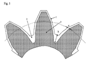
図1は、本発明の歯車の一実施形態の概略図を示す。この実施形態においては、表皮層は、その表面が通常の歯形(一般にインボリュート歯形)に合致している一方、内側がギアコアに結合している。歯(2)の歯底における表皮(1)の厚さ(「X」として示される)は、半径方向において、ギアのピッチ線における表皮(1)の厚さ(「Y」として示される)より厚い。図中で円形の点線として示されるピッチ線は、通常、基準直径または噛み合いピッチ円直径と呼ばれる。ピッチ線は、歯形を歯先と歯元とに分ける。ギアが噛み合うと、歯形がスライドして、この線における歯形の方向が変わる。したがって、本明細書において、厚さはギアの摩耗性能に関して重要性を有する。 FIG. 1 shows a schematic diagram of one embodiment of the gear of the present invention. In this embodiment, the skin layer has a surface that conforms to a normal tooth profile (generally an involute tooth profile), while the inside is bonded to the gear core. The thickness of the skin (1) at the root of the tooth (2) (indicated as “X”) is, in the radial direction, the thickness of the skin (1) at the gear pitch line (indicated as “Y”). thick. The pitch line shown as a circular dotted line in the figure is usually called the reference diameter or the meshing pitch circle diameter. The pitch line divides the tooth profile into a tooth tip and a tooth base. When the gears mesh, the tooth profile slides, changing the direction of the tooth profile in this line. Therefore, thickness is important here with respect to gear wear performance.
歯底における表皮の厚さ「X」は、歯車の半径方向における表皮の外面とコアの外面との間の長さと定義される。コアは、1つのパーツで(図1を参照)または組み合わせて(図3を参照)円形を構成する部分である。図1に示されるように1つのパーツがコア部分および歯部分を有する場合、コアは内側部分であり、それに突出した歯が結合されている。 The thickness “X” of the skin at the root is defined as the length between the outer surface of the skin and the outer surface of the core in the radial direction of the gear. The core is a part that forms a circle in one part (see FIG. 1) or in combination (see FIG. 3). As shown in FIG. 1, when one part has a core part and a tooth part, the core is an inner part, and protruding teeth are connected to it.
歯のピッチ線における表皮の厚さ「Y」は、歯車の周方向における表皮の外面と歯の外面との間の長さと定義される。 The skin thickness “Y” at the tooth pitch line is defined as the length between the outer surface of the skin and the outer surface of the tooth in the circumferential direction of the gear.
この構成では、コアの形状は、細長いまたは丈が長いギア自体と同様であるが、表皮がコアの形状にかかわらず歯形の正確な形状に合致することになるため、コアの形状の正確さに関しては要求が少ない(less demanding)であろう。コアの歯丈は、表皮の厚さの結果としてだけでなく、表皮とコア材料との所与の組合せで行われる計算の結果として求められ得る。ここではコアが比較的細長いため、コアの強度は、頑丈な丈の低いギアの場合と異なり、せん断より曲げによって決まる。 In this configuration, the shape of the core is similar to the elongated or lengthy gear itself, but with respect to the accuracy of the core shape, because the epidermis will match the exact shape of the tooth profile regardless of the shape of the core. Would be less demanding. The tooth height of the core can be determined not only as a result of the skin thickness, but also as a result of calculations performed on a given combination of skin and core material. Since the core is relatively elongated here, the strength of the core is determined by bending rather than shear, unlike the case of a sturdy, low-gear gear.
図2は、本発明によってもたらされる技術的効果を概略的に示す。この概念の2層のギアは、周囲を厚い表皮が支持している歯底ではなく歯形部分における曲げ応力のために設計され得る。歯底における厚い表皮は、小さい質量より大きい質量が変形する場合の歯底における応力の急激な増大に対する緩衝材となる。ナイロンなどの高伸長性材料を表皮に用い、ガラス強化プラスチックなどの硬質材料をコアに用いることによって、最大ギア強度は、コアの曲げ応力および表皮のせん断応力が同時にその強度に達したときに得られるであろう。 FIG. 2 schematically illustrates the technical effects brought about by the present invention. This concept of a two-layer gear can be designed for bending stresses in the tooth profile rather than in the roots supported by the thick skin around it. The thick epidermis at the root of the tooth provides a buffer against a sudden increase in stress at the root when a mass greater than a small mass is deformed. By using a highly extensible material such as nylon for the skin and a hard material such as glass reinforced plastic for the core, maximum gear strength is obtained when the core bending stress and skin shear stress reach that strength simultaneously. Will be done.
表皮の最適厚さは計算によって求められ得、この計算では、歯底におけるせん断応力およびコアにおける曲げ応力が使用時の各材料の強度に達するものである。 The optimum thickness of the skin can be determined by calculation, where the shear stress at the root and the bending stress at the core reach the strength of each material in use.
図3は、分断されたギアの歯が結合層(4)によって組み合わされるものである、本発明の別の実施形態を示す。この構成は、いくつかのアンダーカットが形成されるべきウォーム歯車などの複雑なギアを可能にし得る。結合層(4)は、表皮(1)と同じ組成からなる。したがって、形成された歯車として、結合層(4)は表皮として働く。歯(2)の歯底における表皮(1)の厚さ(「X」として示される)は、歯(2)のピッチ線における表皮(1)の厚さ(「Y」として示される)より厚い。 FIG. 3 shows another embodiment of the invention in which the separated gear teeth are combined by a tie layer (4). This configuration may allow complex gears such as worm gears in which some undercuts are to be formed. The bonding layer (4) has the same composition as the skin (1). Therefore, as a formed gear, the coupling layer (4) acts as a skin. The thickness of the epidermis (1) at the root of the tooth (2) (denoted as "X") is thicker than the thickness of the epidermis (1) at the pitch line of the tooth (2) (denoted as "Y") .
上述した設計(図1)の場合、ギアの歯の歯底における表皮の壁部分が厚いことは、その部分が歯底における応力集中により耐えられ;ひいては、歯底における表皮が、壁部分の形状が一定である場合より変形し得ることを意味する。 In the case of the above-described design (FIG. 1), the thicker skin part of the gear tooth bottom is able to withstand the stress concentration at the tooth bottom; Means that it can be deformed more than when it is constant.
歯底における前記表皮の厚さは、好ましくは歯のピッチ線における前記表皮の厚さの1.5〜10倍、より好ましくは歯のピッチ線における前記表皮の厚さの1.5〜10倍である。歯底における表皮層が厚過ぎると、材料の弾性係数に応じて、歯車が脆弱になることがある。 The thickness of the epidermis at the tooth bottom is preferably 1.5 to 10 times the thickness of the epidermis at the tooth pitch line, more preferably 1.5 to 10 times the thickness of the epidermis at the tooth pitch line. It is. If the skin layer at the root is too thick, the gear may become brittle depending on the elastic modulus of the material.
歯の形状は限定されないが;本発明の歯車の歯は、歯底に厚い表皮のない歯車と比較して、歯の内側に第1の材料でできた比較的長いまたは細長い形状を有する。同じ表面形状を有する歯車が製造される場合、本発明の歯車は、歯底における表皮がより厚いため、歯を構成する第1の材料でできた比較的長く、細長い形状を有する。噛み合い時の接線分力が一定として、本発明のギアは、表皮または第2の材料が均一な厚さを有する場合より変形し得る。本発明のギアでは、歯底における表皮およびコアの両方の角隅部が互いに近接しておらず;ひいては応力集中による脆弱な領域も同様である。表皮より伸びの少ないコアは、深部のコア底よりも負担のかかる表皮に先立ってその構造的限界に達しないことになる。ギアは、使用時に単一の材料の強度に影響されないため、全体として良好に機能する。 The shape of the teeth is not limited; the teeth of the gears of the present invention have a relatively long or elongated shape made of the first material inside the teeth compared to a gear without a thick skin at the root. When gears having the same surface shape are produced, the gears of the present invention have a relatively long, elongated shape made of the first material that constitutes the teeth, due to the thicker skin at the root. As the tangential component force at the time of meshing is constant, the gear of the present invention can be deformed more than when the skin or the second material has a uniform thickness. In the gear of the present invention, the corners of both the epidermis and the core at the root are not close to each other, and so is the fragile region due to stress concentration. A core that stretches less than the epidermis will not reach its structural limit prior to the epidermis being more burdensome than the deep core bottom. The gear works well as a whole because it is not affected by the strength of a single material in use.
第1および第2の材料自体の機械的特性が、他の領域に対する、歯底における表皮の適切な厚さについての最適な形状的バランスを決定し得ることは明らかである。ここまで説明したような概念によるギアの特定の設計形状は、Finite Element Analysisによるものなどの緻密な(elaborate)構造計算によって決定され得る。 It is clear that the mechanical properties of the first and second materials themselves can determine the optimal geometric balance for the appropriate thickness of the epidermis at the root of the tooth relative to other areas. The specific design shape of the gear according to the concepts as described so far can be determined by elaborate structural calculations such as those by Finite Element Analysis.
接触している、異なる材料の磨耗および摩滅性能は、場合により良好であることが分かっており、第1および第2の材料が適切に選択された場合、提案されるギアの形状は、上記の利点を容易に提供し得る。 The wear and wear performance of different materials in contact has been found to be better in some cases, and when the first and second materials are properly selected, the proposed gear shape is Benefits can be easily provided.
第1および第2の材料は、歯車に所望の特性を与える任意の熱可塑性ポリマーを含み得る。本発明の一実施形態においては、第1の材料は、所望の曲げ強度、剛性および耐衝撃性をコアに与える硬質ポリマーであり、第2の材料は、使用時の静音性能を与える軟質ポリマーであり得る。これらのポリマーは、同じ化学種のもの、例えば両方ともポリアミドであるか、または異なる化学種のもの、例えばポリアミドおよびポリエステルであり得る。両方の材料に用いられ得るポリマーの組合せの例は、ポリアミドとポリエステルとのブロックコポリマー(Zytel(登録商標)−Hytrel(登録商標))、ポリエステル、(Ryntie(登録商標)/Crastin(登録商標)−Rynite(登録商標)/Crastin(登録商標))、ポリアセタールとポリアセタール(Delrin(登録商標)−Delrin(登録商標))、非強化またはガラス/鉱物で強化したポリアセタールとポリアミド(Delrin(登録商標)−Zytel(登録商標)/Minlon(登録商標))であり、全てDu Pont Company(Wilmington,DE)から入手可能である。当業者は、必要以上の実験を行わずに、2種の材料を含む的確な分子量グレードを規定することができるであろう。 The first and second materials can include any thermoplastic polymer that provides the desired properties to the gear. In one embodiment of the present invention, the first material is a hard polymer that provides the core with the desired bending strength, stiffness and impact resistance, and the second material is a soft polymer that provides quiet performance in use. possible. These polymers can be of the same chemical species, eg both polyamides, or of different chemical species, eg polyamides and polyesters. Examples of polymer combinations that can be used for both materials are block copolymers of polyamide and polyester (Zytel®-Hytrel®), polyester, (Ryntie® / Crastin®)- Rynite® / Crastin®), polyacetals and polyacetals (Delrin®-Delrin®), non-reinforced or glass / mineral reinforced polyacetals and polyamides (Delrin®-Zytel (Registered trademark) / Minlon (registered trademark)), all available from Du Pont Company (Wilmington, DE). One skilled in the art will be able to define an accurate molecular weight grade that includes two materials without undue experimentation.
本発明の生成物に用いられ得るポリマーは、上に挙げた市販の材料に限定されない。結合可能なポリマーの任意の組合せを用いることができる。本発明の生成物の製造に用いることができる熱可塑性ポリマーに特に制限はない。熱可塑性ポリマーの例としては、ポリエチレンテレフタレート、ポリブチレンテレフタレート、ポリエチレンナフタレート、およびポリブチレンナフタレートなどの芳香族ポリエステル;ポリエチレンおよびポリプロピレンなどのポリオレフィン;ポリアセタール(ホモポリマーおよびコポリマー);ポリスチレン、スチレン−ブタジエンコポリマー、アクリロニトリル−ブタジエン−スチレンコポリマー、スチレン−ブタジエン−アクリル酸(またはそのエステル)コポリマー、およびアクリロニトリル−スチレンコポリマー;ポリ塩化ビニル;ポリアミド;ポリ(フェニレンオキシド);ポリ(フェニレンスルフィド);ポリスルホン;ポリエーテル−スルホン;ポリケトン;ポリエーテル−ケトン;ポリイミド;ポリエーテル−イミド;ポリベンズイミダゾール;ポリブタジエンおよびブチルゴム;シリコーン樹脂;フッ素樹脂;オレフィン系熱可塑性エラストマー、スチレン系熱可塑性エラストマー、ウレタン系熱可塑性エラストマー、ポリエステル系熱可塑性エラストマー、ポリアミド系熱可塑性エラストマー、およびポリエーテル系熱可塑性エラストマー;ポリアクリレート系、芯−鞘型、多層グラフトコポリマー;およびそれらの変性された生成物が挙げられる。これらの熱可塑性樹脂は、2種以上の化学種を組み合わせて用いられてもよい。 The polymers that can be used in the products of the present invention are not limited to the commercially available materials listed above. Any combination of attachable polymers can be used. There is no particular limitation on the thermoplastic polymer that can be used to produce the product of the present invention. Examples of thermoplastic polymers include polyethylene terephthalate, polybutylene terephthalate, polyethylene naphthalate, and aromatic polyesters such as polybutylene naphthalate; polyolefins such as polyethylene and polypropylene; polyacetals (homopolymers and copolymers); polystyrene, styrene-butadiene Copolymer, acrylonitrile-butadiene-styrene copolymer, styrene-butadiene-acrylic acid (or ester thereof) copolymer, and acrylonitrile-styrene copolymer; polyvinyl chloride; polyamide; poly (phenylene oxide); poly (phenylene sulfide); polysulfone; -Sulfone; polyketone; polyether-ketone; polyimide; polyether-imide Polybenzimidazole; Polybutadiene and butyl rubber; Silicone resin; Fluororesin; Olefin thermoplastic elastomer, Styrenic thermoplastic elastomer, Urethane thermoplastic elastomer, Polyester thermoplastic elastomer, Polyamide thermoplastic elastomer, and Polyether thermoplastic Elastomers; polyacrylate-based, core-sheath, multi-layer graft copolymers; and their modified products. These thermoplastic resins may be used in combination of two or more chemical species.
液晶ポリエステル(LCP)を本発明の生成物の製造に用いることができる。LCPの例は、
(i)2,6−ナフタレンジカルボン酸、2,6−ジヒドロキシナフタレン、1,4−ジヒドロキシナフタレン、および6−ヒドロキシ−2−ナフトエ酸などのナフタレン化合物;
(ii)4,4’−ジフェニルジカルボン酸および4,4−ジヒドロキシビフェニルなどのビフェニル化合物;
(iii)p−ヒドロキシ安息香酸、テレフタル酸、ヒドロキノン、p−アミノフェノール、およびp−フェニレンジアミンなどのp−置換ベンゼン化合物、およびそれらの核置換ベンゼン化合物(核置換基は、塩素、臭素、C1〜C4アルキル、フェニル、および1−フェニルエチルから選択される);ならびに
(iv)イソフタル酸およびレゾルシンなどのm−置換ベンゼン化合物、およびそれらの核置換ベンゼン化合物(核置換基は、塩素、臭素、C1〜C4アルキル、フェニル、および1−フェニルエチルから選択される)
を含むモノマーから調製されるものである。
Liquid crystalline polyester (LCP) can be used to produce the product of the present invention. An example of LCP is
(I) naphthalene compounds such as 2,6-naphthalenedicarboxylic acid, 2,6-dihydroxynaphthalene, 1,4-dihydroxynaphthalene, and 6-hydroxy-2-naphthoic acid;
(Ii) biphenyl compounds such as 4,4′-diphenyldicarboxylic acid and 4,4-dihydroxybiphenyl;
(Iii) p-substituted benzene compounds such as p-hydroxybenzoic acid, terephthalic acid, hydroquinone, p-aminophenol, and p-phenylenediamine, and their nuclear substituted benzene compounds (the nuclear substituents are chlorine, bromine, C1 And (iv) m-substituted benzene compounds such as isophthalic acid and resorcin, and their nuclear substituted benzene compounds (nuclear substituents are chlorine, bromine, Selected from C1-C4 alkyl, phenyl, and 1-phenylethyl)
It is prepared from a monomer containing
上記のモノマーの中でも特に、ナフタレン化合物、ビフェニル化合物、およびp−置換ベンゼン化合物の中から選択される少なくとも1種または複数の化学種から調製される液晶ポリエステルが、本発明の製造に用いられる液晶ポリエステルとしてより好ましい。 Among the above monomers, a liquid crystal polyester prepared from at least one or more chemical species selected from naphthalene compounds, biphenyl compounds, and p-substituted benzene compounds is used for the production of the present invention. Is more preferable.
p−置換ベンゼン化合物、p−ヒドロキシ安息香酸、メチルヒドロキノン、および1−フェニルエチルヒドロキノンの中のものが特に好ましい。 Particularly preferred are p-substituted benzene compounds, p-hydroxybenzoic acid, methylhydroquinone, and 1-phenylethylhydroquinone.
上記のモノマーに加えて、本発明に用いられる液晶ポリエステルは、その1つの分子鎖中に、異方性の溶融相を呈さないポリアルキレンテレフタレート部分を含有し得る。この場合、アルキル基が2〜4個の炭素原子を有する。 In addition to the above monomers, the liquid crystal polyester used in the present invention may contain a polyalkylene terephthalate portion that does not exhibit an anisotropic melt phase in one molecular chain. In this case, the alkyl group has 2 to 4 carbon atoms.
本発明の生成物の製造に用いられる熱可塑性物質に添加され得る物質または添加剤としては、限定はされないが、耐熱安定剤、紫外線吸収剤、離型剤、帯電防止剤、スリップ剤、粘着防止剤、滑剤、曇り防止剤、着色剤、天然油、合成油、ワックス、有機充填剤、無機充填剤、およびそれらの混合物が挙げられる。 Substances or additives that can be added to the thermoplastic used in the production of the product of the present invention are not limited, but include heat-resistant stabilizers, UV absorbers, mold release agents, antistatic agents, slip agents, and anti-sticking agents. Agents, lubricants, antifogging agents, colorants, natural oils, synthetic oils, waxes, organic fillers, inorganic fillers, and mixtures thereof.
上記の耐熱安定剤の例としては、限定はされないが、フェノール安定剤、有機チオエーテル安定剤、有機亜リン酸塩安定剤、ヒンダードアミン安定剤、エポキシ安定剤およびそれらの混合物が挙げられる。耐熱安定剤は、固体または液体の形態で添加されてもよい。 Examples of the above heat stabilizer include, but are not limited to, phenol stabilizers, organic thioether stabilizers, organic phosphite stabilizers, hindered amine stabilizers, epoxy stabilizers and mixtures thereof. The heat stabilizer may be added in solid or liquid form.
紫外線吸収剤の例としては、限定はされないが、サリチル酸紫外線吸収剤、ベンゾフェノン紫外線吸収剤、ベンゾトリアゾール紫外線吸収剤、シアノアクリレート紫外線吸収剤、およびそれらの混合物が挙げられる。 Examples of UV absorbers include, but are not limited to, salicylic acid UV absorbers, benzophenone UV absorbers, benzotriazole UV absorbers, cyanoacrylate UV absorbers, and mixtures thereof.
離型剤の例としては、限定はされないが、天然パラフィンおよび合成パラフィン、ポリエチレンワックス、フッ化炭素、および他の炭化水素離型剤;ステアリン酸、ヒドロキシステアリン酸、および他の高級脂肪酸、ヒドロキシ脂肪酸、および他の脂肪酸離型剤;ステアリン酸アミド、エチレンビスステアロアミド、および他の脂肪酸アミド、アルキレンビス脂肪酸アミド、および他の脂肪酸アミド離型剤;ステアリルアルコール、セチルアルコール、および他の脂肪族アルコール、多価アルコール、ポリグリコール、ポリグリセロールおよび他のアルコール離型剤;ステアリン酸ブチル、テトラステアリン酸ペンタエリトリトール、および脂肪酸の他の低級アルコールエステル、脂肪酸の多価アルコールエステル、脂肪酸のポリグリコールエステル、および他の脂肪酸エステル離型剤;シリコーン油および他のシリコーン離型剤、および上記のもののいずれかの混合物が挙げられる。 Examples of release agents include, but are not limited to, natural and synthetic paraffins, polyethylene waxes, fluorocarbons, and other hydrocarbon release agents; stearic acid, hydroxystearic acid, and other higher fatty acids, hydroxy fatty acids , And other fatty acid release agents; stearic acid amide, ethylene bis stearamide, and other fatty acid amides, alkylene bis fatty acid amide, and other fatty acid amide release agents; stearyl alcohol, cetyl alcohol, and other aliphatics Alcohols, polyhydric alcohols, polyglycols, polyglycerols and other alcohol release agents; butyl stearate, pentaerythritol tetrastearate, and other lower alcohol esters of fatty acids, polyhydric alcohol esters of fatty acids, polyglycols of fatty acids Ester, and other fatty acid ester mold release agents; silicone oils and other silicone mold release agents, and mixtures of any of the above are mentioned.
着色剤は、顔料または染料のいずれかであり得る。無機着色剤および有機着色剤は、本発明において別々にまたは組み合わせて用いられてもよい。 The colorant can be either a pigment or a dye. Inorganic and organic colorants may be used separately or in combination in the present invention.
第1の材料と第2の材料との結合は、当業者に公知の任意の手段によって行うことができる。本発明の一実施形態においては、結合は、第1の材料より高い融解潜熱を有するポリマーを第2の材料として用いることによって行うことができる。歯車の製造方法において、第2の材料は、第1の材料を含むコア上に成形される。機構(mechanism)に制約されることを望むものではないが、第2の材料の冷却および結晶化からの残りのエンタルピー(residual enthalpy)が、第1の材料の薄層の再溶融およびその後の融解、ひいては成形圧力下での第1の材料と第2の材料との結合を引き起こすことが可能である。本発明の他の実施形態においては、結合は、プライマーまたは第1の材料と第2の材料との間の接着剤層を使用することによって行われる。用いられるべき第1の材料および第2の材料がポリアミドのグレードである場合、例えば、山清工業株式会社(Yamasei Kogyo Co.,Ltd.)による「Cling−Aid」という製品名の、ポリアミド樹脂用イソプロパノール系結合剤が、このようなプライマーの例である。「Cling−Aid」は、没食子酸(CAS番号149−91−7)をイソプロパノールに溶かした溶液を含む。 The bonding of the first material and the second material can be performed by any means known to those skilled in the art. In one embodiment of the invention, the bonding can be performed by using a polymer having a higher latent heat of fusion than the first material as the second material. In the gear manufacturing method, the second material is formed on a core including the first material. Although not wishing to be constrained by the mechanism, the residual enthalpy from cooling and crystallization of the second material is responsible for the remelting and subsequent melting of the thin layer of the first material. In turn, it is possible to cause a bond between the first material and the second material under molding pressure. In other embodiments of the invention, the binding is performed by using a primer or an adhesive layer between the first material and the second material. When the first material and the second material to be used are polyamide grades, for example, for polyamide resins with the product name “Cling-Aid” by Yamasei Kogyo Co., Ltd. An isopropanol-based binder is an example of such a primer. “Cling-Aid” includes a solution of gallic acid (CAS No. 149-91-7) dissolved in isopropanol.
第1の材料上に成形されるべき第2の材料は、コアおよび表皮の両方による複合断面係数を低下させないよう十分薄くする必要がある。厚過ぎる場合、複合断面の最外層が係数の計算にコアより大きな影響を与えるため、係数は大きな影響を受け得る。潤滑性/耐摩耗性の寄与についての表皮の所要の厚さは、ギアモジュールに応じて0.2〜0.5である:表皮の材料がコアより柔らかいことに起因する必然的な係数の低下が変わらない場合、モジュールが大きくなるほど表皮は厚くなるが、厚さは、材料を流すことができる限り最小に保たれるべきである。 The second material to be molded on the first material needs to be thin enough so as not to reduce the composite section modulus due to both the core and the skin. If it is too thick, the coefficient can be greatly affected because the outermost layer of the composite cross section has a greater influence on the coefficient calculation than the core. The required thickness of the skin for the lubricity / wear resistance contribution is between 0.2 and 0.5, depending on the gear module: an inevitable factor reduction due to the skin material being softer than the core If does not change, the larger the module, the thicker the skin, but the thickness should be kept to the minimum possible to allow the material to flow.
厚さが半径方向にのみ変化する場合、ギアの歯底における表皮を厚くすることは、係数の低下がより大きくなることを意味しない。壁の厚さが不均一であること(ピッチ線では薄く、歯底では厚い)により、プラスチック流れが一定でなく、結果として薄い部分に溶接線が形成されるという問題が生じ得るという懸念があり得る。しかしながら、これは、ゲート(そこからプラスチックが充填されることになる)および通気孔(そこからプラスチック流れによる圧縮ガスが放出されることになる)を適切に配置することによって克服され得る。また、領域にそれほど応力がかからない場合、ギアの歯先において形成されがちな溶接線は問題にならないであろう。そのため、コアおよび最終的な部品の形状が均一でないことに起因する厚さの不均一は、本発明の概念を損なわないであろう。 If the thickness changes only in the radial direction, thickening the epidermis at the gear root does not mean that the reduction in the coefficient is greater. There is concern that the wall thickness may be uneven (thin for pitch lines and thick for roots), causing plastic flow to be inconsistent, resulting in the formation of weld lines in thin areas. obtain. However, this can be overcome by properly positioning the gate (from which the plastic will be filled) and the vent (from which the compressed gas from the plastic flow will be released). Also, if the area is not so stressed, the weld lines that tend to form at the gear teeth will not be a problem. Thus, non-uniform thickness due to non-uniform core and final part shapes will not detract from the concept of the present invention.
コアの第1の材料と表皮の第2の材料との間の結合の引張り強さは、結合の面に対して垂直に引張測定を行うことによって測定した際に、20Mpaを超えるべきである。好ましくは、引張り強さは50Mpaを超え、最も好ましくは80Mpaを超えるべきである。 The tensile strength of the bond between the first material of the core and the second material of the skin should be greater than 20 Mpa, as measured by making a tensile measurement perpendicular to the plane of the bond. Preferably the tensile strength should be greater than 50 Mpa, and most preferably greater than 80 Mpa.
本発明は、さらに、熱可塑性ポリマーを含む複合歯車の製造方法に関する。本発明の一実施形態においては、本方法は、
i.歯を有するコアを第1の材料から成形する工程と、
ii.第1の材料を固化させる工程と、
iii.歯底における前記表皮の厚さが、歯のピッチ線における前記表皮の厚さより厚くなり得るように、歯にわたって第2の材料で作製された表皮を成形する工程とを含む。
The present invention further relates to a method of manufacturing a compound gear including a thermoplastic polymer. In one embodiment of the invention, the method comprises:
i. Forming a core having teeth from a first material;
ii. Solidifying the first material;
iii. Molding a skin made of a second material over the teeth such that the thickness of the skin at the root of the tooth can be greater than the thickness of the skin at the tooth pitch line.
IIとIIIとの間に、表皮を成形する工程の前にコアにプライマーを塗布する工程を任意選択的に入れることができる。プライマーは、当業者に公知の任意の手段によって塗布され得る。例えば、ブラシによる手作業での塗布などである。 A step of applying a primer to the core can optionally be inserted between II and III before the step of forming the skin. The primer may be applied by any means known to those skilled in the art. For example, manual application with a brush.
第1の材料からのコアの成形は、当業者に公知の任意の成形方法によって行うことができる。例えば、射出成形機が周知であり、東芝(Toshiba)、住友(Sumitomo)、日精(Nissei)、ファナック(Fanuc)、Battenfeld、Engelsなどの多くの製造業者によって製造されている。射出成形プロセスにおいては、溶融ポリマーが、所要の形状および寸法の金型に圧力下に注入される。この金型は冷却され、最終部品が取り出される。本発明の方法では、取り出された部品は、必要に応じてトリミングされた後、第2の材料の2回目の注入用のコアとして用いられる。ポリマーの2回目の注入によって加えられるべき圧力がコアを変形または変位させる(これがギアの寸法を不正確にする)ことのないように、コアは金型内にしっかりと保持される必要がある。金型におけるコアの移動は、通常、「コアずれ」と呼ばれ、圧力の不均衡が大きくなるときに特に著しい。この不均衡を最小限に抑えるために、充填の任意の所与のタイミングにおけるコアのあらゆる側にかかる圧力が互いに相殺され得るように、第2の材料の流路を決定すべきである。例えば、コアの前側および裏側における溶融物の前進が等しい場合、それによってコアにかかる圧力は、平衡状態において想定され得る。コア上に表皮を形成する第2の材料は必然的に、1つの側、すなわちキャビティの側に充填されることになる。そのため、考慮事項が特にない場合、溶融物がコアの側よりキャビティの側に速く広がるにつれて、コアがコアの側に向かって変形し得る。本発明の一実施形態においては、穿孔をコアに任意選択的に設けることは、コアの両側をつなぐ流路を提供し、それによりコアにかかる圧力の均衡をとることを意味する。 Molding of the core from the first material can be performed by any molding method known to those skilled in the art. For example, injection molding machines are well known and are manufactured by many manufacturers such as Toshiba, Sumitomo, Nissei, Fanuc, Battenfeld, Engels and others. In the injection molding process, molten polymer is injected under pressure into a mold of the required shape and dimensions. The mold is cooled and the final part is removed. In the method of the present invention, the removed part is trimmed as necessary and then used as the core for the second injection of the second material. The core needs to be held firmly in the mold so that the pressure to be applied by the second injection of polymer does not deform or displace the core (which makes the gear dimensions inaccurate). The movement of the core in the mold is usually referred to as “core misalignment” and is particularly noticeable when the pressure imbalance increases. In order to minimize this imbalance, the flow path of the second material should be determined so that the pressures on all sides of the core at any given timing of filling can cancel each other. For example, if the melt advancement on the front and back sides of the core is equal, the pressure on the core can thereby be assumed at equilibrium. The second material that forms the skin on the core will necessarily be filled on one side, the side of the cavity. Thus, if there are no particular considerations, the core may be deformed toward the core as the melt spreads more quickly toward the cavity than from the core. In one embodiment of the present invention, optionally providing perforations in the core means providing a flow path connecting both sides of the core, thereby balancing the pressure on the core.
Claims (6)
I.歯を有するコアを第1の材料から成形する工程と、
II.前記第1の材料を固化させる工程と、
III.歯底における前記表皮の厚さが、前記歯のピッチ線における前記表皮の厚さより厚くなり得るように、前記歯にわたって第2の材料で作製された表皮を成形する工程と
を含む方法。 A method of manufacturing a gear,
I. Forming a core having teeth from a first material;
II. Solidifying the first material;
III. Molding a skin made of a second material over the teeth such that the thickness of the skin at the root of the tooth can be greater than the thickness of the skin at the pitch line of the teeth.
Applications Claiming Priority (2)
| Application Number | Priority Date | Filing Date | Title |
|---|---|---|---|
| US99344307P | 2007-09-12 | 2007-09-12 | |
| PCT/US2008/075951 WO2009036122A1 (en) | 2007-09-12 | 2008-09-11 | Composite gear |
Publications (2)
| Publication Number | Publication Date |
|---|---|
| JP2010539414A true JP2010539414A (en) | 2010-12-16 |
| JP2010539414A5 JP2010539414A5 (en) | 2011-10-27 |
Family
ID=40085467
Family Applications (1)
| Application Number | Title | Priority Date | Filing Date |
|---|---|---|---|
| JP2010524974A Pending JP2010539414A (en) | 2007-09-12 | 2008-09-11 | Compound gear |
Country Status (5)
| Country | Link |
|---|---|
| US (1) | US20090081402A1 (en) |
| EP (1) | EP2188549A1 (en) |
| JP (1) | JP2010539414A (en) |
| CN (1) | CN101802457A (en) |
| WO (1) | WO2009036122A1 (en) |
Families Citing this family (6)
| Publication number | Priority date | Publication date | Assignee | Title |
|---|---|---|---|---|
| WO2010062774A2 (en) * | 2008-11-03 | 2010-06-03 | Edlebrock Corporation | Supercharger system for motorized vehicles and related transportation |
| US10202892B2 (en) | 2008-11-03 | 2019-02-12 | Edelbrock Corporation | Supercharger system for motorized vehicles and related transportation |
| JP6254853B2 (en) * | 2014-01-22 | 2017-12-27 | 株式会社エンプラス | Two-color molding method and two-color molding |
| US11248692B2 (en) * | 2016-03-11 | 2022-02-15 | Deere & Company | Composite gears and methods of manufacturing such gears |
| US10823269B2 (en) * | 2017-01-12 | 2020-11-03 | Shimano Inc. | Bicycle rotor |
| DE102018209050A1 (en) * | 2018-06-07 | 2019-12-12 | Robert Bosch Gmbh | Plastic gear and steering gear |
Citations (5)
| Publication number | Priority date | Publication date | Assignee | Title |
|---|---|---|---|---|
| US1199084A (en) * | 1915-11-04 | 1916-09-26 | Henry P Kraft | Valve-repair tool. |
| JPS6170269A (en) * | 1984-09-12 | 1986-04-11 | Nippon Poripenko Kk | Nylon gear containing core bar |
| JP2001304379A (en) * | 2000-04-20 | 2001-10-31 | Unisia Jecs Corp | Synthetic resin gear and manufacturing method therefor |
| JP2004346981A (en) * | 2003-05-20 | 2004-12-09 | Asmo Co Ltd | Resin gear |
| US20070089555A1 (en) * | 2005-10-21 | 2007-04-26 | Koji Tomoda | Composite gear |
Family Cites Families (6)
| Publication number | Priority date | Publication date | Assignee | Title |
|---|---|---|---|---|
| US3719103A (en) * | 1971-10-07 | 1973-03-06 | Design Systems | Laminated gear construction |
| US4143973A (en) * | 1977-11-28 | 1979-03-13 | The J. B. Foote Foundry Co. | Gear |
| US5852951A (en) * | 1994-10-04 | 1998-12-29 | Briggs & Stratton Corporation | Composite gear and method of making same |
| JPH0989081A (en) * | 1995-09-28 | 1997-03-31 | Fuji Heavy Ind Ltd | Injection molding gear for general purpose engine and manufacture thereof |
| JP3631084B2 (en) * | 1999-09-13 | 2005-03-23 | 光洋精工株式会社 | Coated product, method for producing the same, and coating apparatus |
| JP2004052791A (en) * | 2002-07-16 | 2004-02-19 | Hitachi Unisia Automotive Ltd | Rotary type power transmitting member and its manufacturing method |
-
2008
- 2008-09-10 US US12/283,178 patent/US20090081402A1/en not_active Abandoned
- 2008-09-11 EP EP08830069A patent/EP2188549A1/en not_active Withdrawn
- 2008-09-11 JP JP2010524974A patent/JP2010539414A/en active Pending
- 2008-09-11 CN CN200880107354.9A patent/CN101802457A/en active Pending
- 2008-09-11 WO PCT/US2008/075951 patent/WO2009036122A1/en active Application Filing
Patent Citations (5)
| Publication number | Priority date | Publication date | Assignee | Title |
|---|---|---|---|---|
| US1199084A (en) * | 1915-11-04 | 1916-09-26 | Henry P Kraft | Valve-repair tool. |
| JPS6170269A (en) * | 1984-09-12 | 1986-04-11 | Nippon Poripenko Kk | Nylon gear containing core bar |
| JP2001304379A (en) * | 2000-04-20 | 2001-10-31 | Unisia Jecs Corp | Synthetic resin gear and manufacturing method therefor |
| JP2004346981A (en) * | 2003-05-20 | 2004-12-09 | Asmo Co Ltd | Resin gear |
| US20070089555A1 (en) * | 2005-10-21 | 2007-04-26 | Koji Tomoda | Composite gear |
Also Published As
| Publication number | Publication date |
|---|---|
| WO2009036122A1 (en) | 2009-03-19 |
| US20090081402A1 (en) | 2009-03-26 |
| EP2188549A1 (en) | 2010-05-26 |
| CN101802457A (en) | 2010-08-11 |
Similar Documents
| Publication | Publication Date | Title |
|---|---|---|
| JP2009512827A (en) | Compound gear | |
| JP2010539414A (en) | Compound gear | |
| JP2015155757A (en) | Composite gear blank and method for manufacturing the same | |
| US20090117401A1 (en) | Composite of metal and resin, and method for manufacturing same | |
| JPH1026195A (en) | Chain guide of tensioner arm, and manufacture thereof | |
| JP2007076638A (en) | Bicycle part made of composite material having insert and its manufacturing method | |
| JP2011251492A (en) | Structure of component made of fiber-reinforced composite material and method of manufacturing the same | |
| US5422150A (en) | Substrate clad with fiber-reinforced polymer composite | |
| CN108527764A (en) | Method for producing composite component | |
| WO2006030810A1 (en) | Method of molding local part by low pressurization and resin-injection molded gear | |
| JP7265431B2 (en) | Structure | |
| CN110382212A (en) | Object is combined together | |
| JP2019195937A (en) | Gear, manufacturing method of the same, and injection mold used for gear manufacturing | |
| WO1995028275A1 (en) | Hollow integral shaft-including structural part of resin and injection molding method for production of the same | |
| CN104379315A (en) | Resin injection molding method and resin injection molded product | |
| JP6715791B2 (en) | Fishing rod having a rod body to which attachment parts are attached, tubular body, and method for manufacturing the same | |
| WO2008105167A1 (en) | Thermoplastic resin injection molded body for laser welding | |
| WO2018174018A1 (en) | Method for manufacturing resin molded body and resin molded body | |
| JP2005214338A (en) | Worm wheel made of resin and manufacturing method therefor | |
| JP2001124127A (en) | Device and method for absorbing impact energy | |
| CN110939650A (en) | Structural body | |
| EP3556533A1 (en) | Plate-shaped molded body manufacturing method, mold, and runner | |
| JP4647239B2 (en) | Outer rotor of trochoid pump and method of manufacturing the same | |
| JP2021138161A (en) | Vehicular suspension member | |
| WO2021010300A1 (en) | Bobbin for coil |
Legal Events
| Date | Code | Title | Description |
|---|---|---|---|
| A521 | Request for written amendment filed |
Free format text: JAPANESE INTERMEDIATE CODE: A523 Effective date: 20110908 |
|
| A621 | Written request for application examination |
Free format text: JAPANESE INTERMEDIATE CODE: A621 Effective date: 20110908 |
|
| A131 | Notification of reasons for refusal |
Free format text: JAPANESE INTERMEDIATE CODE: A131 Effective date: 20130125 |
|
| A601 | Written request for extension of time |
Free format text: JAPANESE INTERMEDIATE CODE: A601 Effective date: 20130424 |
|
| A602 | Written permission of extension of time |
Free format text: JAPANESE INTERMEDIATE CODE: A602 Effective date: 20130502 |
|
| A601 | Written request for extension of time |
Free format text: JAPANESE INTERMEDIATE CODE: A601 Effective date: 20130527 |
|
| A602 | Written permission of extension of time |
Free format text: JAPANESE INTERMEDIATE CODE: A602 Effective date: 20130603 |
|
| A02 | Decision of refusal |
Free format text: JAPANESE INTERMEDIATE CODE: A02 Effective date: 20130816 |