JP2010538192A - Solar collector with angled cooling fins - Google Patents
Solar collector with angled cooling fins Download PDFInfo
- Publication number
- JP2010538192A JP2010538192A JP2010512245A JP2010512245A JP2010538192A JP 2010538192 A JP2010538192 A JP 2010538192A JP 2010512245 A JP2010512245 A JP 2010512245A JP 2010512245 A JP2010512245 A JP 2010512245A JP 2010538192 A JP2010538192 A JP 2010538192A
- Authority
- JP
- Japan
- Prior art keywords
- heat pipe
- solar collector
- heat
- cooling fin
- solar
- Prior art date
- Legal status (The legal status is an assumption and is not a legal conclusion. Google has not performed a legal analysis and makes no representation as to the accuracy of the status listed.)
- Pending
Links
- 238000001816 cooling Methods 0.000 title claims abstract description 53
- 238000000034 method Methods 0.000 claims abstract description 19
- 238000004519 manufacturing process Methods 0.000 claims abstract description 7
- 239000007788 liquid Substances 0.000 claims description 7
- 238000010438 heat treatment Methods 0.000 claims description 2
- 239000003570 air Substances 0.000 description 20
- 239000012080 ambient air Substances 0.000 description 7
- 230000005611 electricity Effects 0.000 description 5
- XEEYBQQBJWHFJM-UHFFFAOYSA-N Iron Chemical compound [Fe] XEEYBQQBJWHFJM-UHFFFAOYSA-N 0.000 description 2
- 230000008859 change Effects 0.000 description 2
- 230000007613 environmental effect Effects 0.000 description 2
- 230000005855 radiation Effects 0.000 description 2
- RYGMFSIKBFXOCR-UHFFFAOYSA-N Copper Chemical compound [Cu] RYGMFSIKBFXOCR-UHFFFAOYSA-N 0.000 description 1
- 239000004020 conductor Substances 0.000 description 1
- 229910052802 copper Inorganic materials 0.000 description 1
- 239000010949 copper Substances 0.000 description 1
- 230000000694 effects Effects 0.000 description 1
- 229910052742 iron Inorganic materials 0.000 description 1
- 230000007246 mechanism Effects 0.000 description 1
- 238000012986 modification Methods 0.000 description 1
- 230000004048 modification Effects 0.000 description 1
- 230000008569 process Effects 0.000 description 1
- XLYOFNOQVPJJNP-UHFFFAOYSA-N water Substances O XLYOFNOQVPJJNP-UHFFFAOYSA-N 0.000 description 1
Images


Classifications
-
- H—ELECTRICITY
- H01—ELECTRIC ELEMENTS
- H01L—SEMICONDUCTOR DEVICES NOT COVERED BY CLASS H10
- H01L31/00—Semiconductor devices sensitive to infrared radiation, light, electromagnetic radiation of shorter wavelength or corpuscular radiation and specially adapted either for the conversion of the energy of such radiation into electrical energy or for the control of electrical energy by such radiation; Processes or apparatus specially adapted for the manufacture or treatment thereof or of parts thereof; Details thereof
- H01L31/04—Semiconductor devices sensitive to infrared radiation, light, electromagnetic radiation of shorter wavelength or corpuscular radiation and specially adapted either for the conversion of the energy of such radiation into electrical energy or for the control of electrical energy by such radiation; Processes or apparatus specially adapted for the manufacture or treatment thereof or of parts thereof; Details thereof adapted as photovoltaic [PV] conversion devices
- H01L31/052—Cooling means directly associated or integrated with the PV cell, e.g. integrated Peltier elements for active cooling or heat sinks directly associated with the PV cells
-
- F—MECHANICAL ENGINEERING; LIGHTING; HEATING; WEAPONS; BLASTING
- F24—HEATING; RANGES; VENTILATING
- F24S—SOLAR HEAT COLLECTORS; SOLAR HEAT SYSTEMS
- F24S10/00—Solar heat collectors using working fluids
- F24S10/90—Solar heat collectors using working fluids using internal thermosiphonic circulation
- F24S10/95—Solar heat collectors using working fluids using internal thermosiphonic circulation having evaporator sections and condenser sections, e.g. heat pipes
-
- F—MECHANICAL ENGINEERING; LIGHTING; HEATING; WEAPONS; BLASTING
- F24—HEATING; RANGES; VENTILATING
- F24S—SOLAR HEAT COLLECTORS; SOLAR HEAT SYSTEMS
- F24S23/00—Arrangements for concentrating solar-rays for solar heat collectors
- F24S23/70—Arrangements for concentrating solar-rays for solar heat collectors with reflectors
- F24S23/71—Arrangements for concentrating solar-rays for solar heat collectors with reflectors with parabolic reflective surfaces
-
- F—MECHANICAL ENGINEERING; LIGHTING; HEATING; WEAPONS; BLASTING
- F24—HEATING; RANGES; VENTILATING
- F24S—SOLAR HEAT COLLECTORS; SOLAR HEAT SYSTEMS
- F24S30/00—Arrangements for moving or orienting solar heat collector modules
- F24S30/40—Arrangements for moving or orienting solar heat collector modules for rotary movement
- F24S30/42—Arrangements for moving or orienting solar heat collector modules for rotary movement with only one rotation axis
- F24S30/425—Horizontal axis
-
- F—MECHANICAL ENGINEERING; LIGHTING; HEATING; WEAPONS; BLASTING
- F24—HEATING; RANGES; VENTILATING
- F24S—SOLAR HEAT COLLECTORS; SOLAR HEAT SYSTEMS
- F24S40/00—Safety or protection arrangements of solar heat collectors; Preventing malfunction of solar heat collectors
- F24S40/50—Preventing overheating or overpressure
- F24S40/55—Arrangements for cooling, e.g. by using external heat dissipating means or internal cooling circuits
-
- H—ELECTRICITY
- H01—ELECTRIC ELEMENTS
- H01L—SEMICONDUCTOR DEVICES NOT COVERED BY CLASS H10
- H01L31/00—Semiconductor devices sensitive to infrared radiation, light, electromagnetic radiation of shorter wavelength or corpuscular radiation and specially adapted either for the conversion of the energy of such radiation into electrical energy or for the control of electrical energy by such radiation; Processes or apparatus specially adapted for the manufacture or treatment thereof or of parts thereof; Details thereof
- H01L31/04—Semiconductor devices sensitive to infrared radiation, light, electromagnetic radiation of shorter wavelength or corpuscular radiation and specially adapted either for the conversion of the energy of such radiation into electrical energy or for the control of electrical energy by such radiation; Processes or apparatus specially adapted for the manufacture or treatment thereof or of parts thereof; Details thereof adapted as photovoltaic [PV] conversion devices
- H01L31/052—Cooling means directly associated or integrated with the PV cell, e.g. integrated Peltier elements for active cooling or heat sinks directly associated with the PV cells
- H01L31/0521—Cooling means directly associated or integrated with the PV cell, e.g. integrated Peltier elements for active cooling or heat sinks directly associated with the PV cells using a gaseous or a liquid coolant, e.g. air flow ventilation, water circulation
-
- H—ELECTRICITY
- H01—ELECTRIC ELEMENTS
- H01L—SEMICONDUCTOR DEVICES NOT COVERED BY CLASS H10
- H01L31/00—Semiconductor devices sensitive to infrared radiation, light, electromagnetic radiation of shorter wavelength or corpuscular radiation and specially adapted either for the conversion of the energy of such radiation into electrical energy or for the control of electrical energy by such radiation; Processes or apparatus specially adapted for the manufacture or treatment thereof or of parts thereof; Details thereof
- H01L31/04—Semiconductor devices sensitive to infrared radiation, light, electromagnetic radiation of shorter wavelength or corpuscular radiation and specially adapted either for the conversion of the energy of such radiation into electrical energy or for the control of electrical energy by such radiation; Processes or apparatus specially adapted for the manufacture or treatment thereof or of parts thereof; Details thereof adapted as photovoltaic [PV] conversion devices
- H01L31/054—Optical elements directly associated or integrated with the PV cell, e.g. light-reflecting means or light-concentrating means
- H01L31/0547—Optical elements directly associated or integrated with the PV cell, e.g. light-reflecting means or light-concentrating means comprising light concentrating means of the reflecting type, e.g. parabolic mirrors, concentrators using total internal reflection
-
- F—MECHANICAL ENGINEERING; LIGHTING; HEATING; WEAPONS; BLASTING
- F24—HEATING; RANGES; VENTILATING
- F24S—SOLAR HEAT COLLECTORS; SOLAR HEAT SYSTEMS
- F24S10/00—Solar heat collectors using working fluids
- F24S10/70—Solar heat collectors using working fluids the working fluids being conveyed through tubular absorbing conduits
- F24S10/75—Solar heat collectors using working fluids the working fluids being conveyed through tubular absorbing conduits with enlarged surfaces, e.g. with protrusions or corrugations
- F24S2010/751—Special fins
- F24S2010/752—Special fins extending obliquely
-
- Y—GENERAL TAGGING OF NEW TECHNOLOGICAL DEVELOPMENTS; GENERAL TAGGING OF CROSS-SECTIONAL TECHNOLOGIES SPANNING OVER SEVERAL SECTIONS OF THE IPC; TECHNICAL SUBJECTS COVERED BY FORMER USPC CROSS-REFERENCE ART COLLECTIONS [XRACs] AND DIGESTS
- Y02—TECHNOLOGIES OR APPLICATIONS FOR MITIGATION OR ADAPTATION AGAINST CLIMATE CHANGE
- Y02E—REDUCTION OF GREENHOUSE GAS [GHG] EMISSIONS, RELATED TO ENERGY GENERATION, TRANSMISSION OR DISTRIBUTION
- Y02E10/00—Energy generation through renewable energy sources
- Y02E10/40—Solar thermal energy, e.g. solar towers
- Y02E10/44—Heat exchange systems
-
- Y—GENERAL TAGGING OF NEW TECHNOLOGICAL DEVELOPMENTS; GENERAL TAGGING OF CROSS-SECTIONAL TECHNOLOGIES SPANNING OVER SEVERAL SECTIONS OF THE IPC; TECHNICAL SUBJECTS COVERED BY FORMER USPC CROSS-REFERENCE ART COLLECTIONS [XRACs] AND DIGESTS
- Y02—TECHNOLOGIES OR APPLICATIONS FOR MITIGATION OR ADAPTATION AGAINST CLIMATE CHANGE
- Y02E—REDUCTION OF GREENHOUSE GAS [GHG] EMISSIONS, RELATED TO ENERGY GENERATION, TRANSMISSION OR DISTRIBUTION
- Y02E10/00—Energy generation through renewable energy sources
- Y02E10/40—Solar thermal energy, e.g. solar towers
- Y02E10/46—Conversion of thermal power into mechanical power, e.g. Rankine, Stirling or solar thermal engines
-
- Y—GENERAL TAGGING OF NEW TECHNOLOGICAL DEVELOPMENTS; GENERAL TAGGING OF CROSS-SECTIONAL TECHNOLOGIES SPANNING OVER SEVERAL SECTIONS OF THE IPC; TECHNICAL SUBJECTS COVERED BY FORMER USPC CROSS-REFERENCE ART COLLECTIONS [XRACs] AND DIGESTS
- Y02—TECHNOLOGIES OR APPLICATIONS FOR MITIGATION OR ADAPTATION AGAINST CLIMATE CHANGE
- Y02E—REDUCTION OF GREENHOUSE GAS [GHG] EMISSIONS, RELATED TO ENERGY GENERATION, TRANSMISSION OR DISTRIBUTION
- Y02E10/00—Energy generation through renewable energy sources
- Y02E10/40—Solar thermal energy, e.g. solar towers
- Y02E10/47—Mountings or tracking
-
- Y—GENERAL TAGGING OF NEW TECHNOLOGICAL DEVELOPMENTS; GENERAL TAGGING OF CROSS-SECTIONAL TECHNOLOGIES SPANNING OVER SEVERAL SECTIONS OF THE IPC; TECHNICAL SUBJECTS COVERED BY FORMER USPC CROSS-REFERENCE ART COLLECTIONS [XRACs] AND DIGESTS
- Y02—TECHNOLOGIES OR APPLICATIONS FOR MITIGATION OR ADAPTATION AGAINST CLIMATE CHANGE
- Y02E—REDUCTION OF GREENHOUSE GAS [GHG] EMISSIONS, RELATED TO ENERGY GENERATION, TRANSMISSION OR DISTRIBUTION
- Y02E10/00—Energy generation through renewable energy sources
- Y02E10/50—Photovoltaic [PV] energy
- Y02E10/52—PV systems with concentrators
Abstract
一実施形態において、太陽集熱器は、熱パイプ及び少なくとも一つの冷却フィンを含む。該少なくとも一つの冷却フィンは熱パイプに対して非垂直第1角で取り付けられている。さらなる実施形態においては、太陽集熱器の製造方法に加え、熱の移動方法が開示される。
【選択図】図1In one embodiment, the solar collector includes a heat pipe and at least one cooling fin. The at least one cooling fin is mounted at a non-vertical first corner with respect to the heat pipe. In a further embodiment, a method for transferring heat is disclosed in addition to a method for manufacturing a solar collector.
[Selection] Figure 1
Description
本開示は、角度付き冷却フィンを備える太陽集熱器に関する。 The present disclosure relates to a solar collector comprising angled cooling fins.
近年、多くの太陽集熱器、その使用方法及び製造方法が存在する。これらの太陽集熱器は太陽放射を電気に変換する為に用いられることがある。既知の太陽集熱器においては、太陽集熱器は反射面、太陽電池、熱パイプ及び複数の冷却フィンを備える。該反射面は、太陽放射を電気に変換して機器に電力を供給する、太陽電池に太陽光を反射する。熱パイプは該太陽電池に取り付けられる。複数の冷却フィンが、熱パイプに対して垂直角に、熱パイプに取り付けられる。太陽電池が熱くなると、過剰な熱は熱パイプへと移動する。熱パイプ内の液体は加熱されて蒸気となり、該蒸気は熱パイプの内部表面を加熱し、加熱された熱パイプの表面は冷却フィンへ熱を移動させ、冷却フィンは自然な対流により熱パイプの周囲の空気へ熱を移動させる。 In recent years, there are many solar collectors, their methods of use and manufacturing methods. These solar collectors are sometimes used to convert solar radiation into electricity. In known solar collectors, the solar collector comprises a reflective surface, a solar cell, a heat pipe and a plurality of cooling fins. The reflective surface reflects sunlight to a solar cell that converts solar radiation into electricity and supplies power to the device. A heat pipe is attached to the solar cell. A plurality of cooling fins are attached to the heat pipe at a perpendicular angle to the heat pipe. When the solar cell gets hot, excess heat is transferred to the heat pipe. The liquid in the heat pipe is heated to become vapor, which heats the inner surface of the heat pipe, the surface of the heated heat pipe transfers heat to the cooling fins, and the cooling fins are heated by the natural convection. Move heat to the surrounding air.
しかしながら、熱パイプに対する冷却フィンの垂直特性のため、熱パイプから周囲の空気への対流熱の伝達率は特定の条件下で減少する。例えば、太陽が太陽集熱器の直上にある場合、該太陽集熱器は地表面に対して平行であり、熱パイプの周りの周囲の空気の流れが無く、熱パイプに対する冷却フィンの垂直な配置は、対流を介した周囲の空気への熱パイプの冷却の助けとはならない。これは、地面に対する冷却フィンの平行な配置は、熱された周囲の空気が上昇するのを困難にするからである。このような状況では、熱パイプが過度の熱を周囲の空気に十分に移動させることができないために、太陽電池が損傷を受けることがある。このようなタイプ又は他のタイプの太陽集熱器には、さらなる問題が存在するかもしれない。 However, due to the vertical nature of the cooling fins relative to the heat pipe, the convective heat transfer rate from the heat pipe to the surrounding air is reduced under certain conditions. For example, if the sun is directly above the solar collector, the solar collector is parallel to the ground surface, there is no ambient air flow around the heat pipe, and the cooling fins are perpendicular to the heat pipe. The arrangement does not help cool the heat pipe to the surrounding air via convection. This is because the parallel arrangement of the cooling fins with respect to the ground makes it difficult for heated ambient air to rise. In such a situation, the solar cell may be damaged because the heat pipes cannot adequately transfer excessive heat to the surrounding air. There may be additional problems with such or other types of solar collectors.
一又は複数の既存の太陽集熱器及び/又は方法に関する一又は複数の問題を減らすために、太陽集熱器、使用方法、及び/又は製造方法が必要である。 In order to reduce one or more problems associated with one or more existing solar collectors and / or methods, solar collectors, methods of use, and / or manufacturing methods are needed.
本開示の一側面において、太陽集熱器は熱パイプ及び少なくとも一つの冷却フィンを備える。該少なくとも一つの冷却フィンは熱パイプに対して非垂直第1角で熱パイプに取り付けられる。 In one aspect of the present disclosure, a solar collector includes a heat pipe and at least one cooling fin. The at least one cooling fin is attached to the heat pipe at a first angle non-perpendicular to the heat pipe.
本開示の他の一側面において、太陽集熱器から熱を移動させる方法が提供される。一ステップでは、熱パイプ、少なくとも一つの冷却フィン、及び太陽電池を備える。該少なくとも一つの冷却フィンは熱パイプに対して非垂直第1角で取り付けられる。さらなるステップでは、太陽光線が太陽電池に反射される。さらなるステップでは、過剰な熱が太陽電池から熱パイプへ移動される。さらなるステップでは、対流を介して、熱パイプから熱パイプ外の周囲の空気へ熱が移動される。 In another aspect of the present disclosure, a method for transferring heat from a solar collector is provided. One step comprises a heat pipe, at least one cooling fin, and a solar cell. The at least one cooling fin is mounted at a non-vertical first corner with respect to the heat pipe. In a further step, sunlight is reflected to the solar cell. In a further step, excess heat is transferred from the solar cell to the heat pipe. In a further step, heat is transferred from the heat pipe to the surrounding air outside the heat pipe via convection.
本開示のさらなる側面では、太陽集熱器の製造方法が提供される。一ステップでは、熱パイプ及び少なくとも一つの冷却フィンが提供される。他のステップでは、少なくとも一つの冷却フィンが熱パイプに対して非垂直第1角で取り付けられる。 In a further aspect of the present disclosure, a method for manufacturing a solar collector is provided. In one step, a heat pipe and at least one cooling fin are provided. In another step, at least one cooling fin is attached to the heat pipe at a non-vertical first corner.
本開示のこれら及び他の特徴、側面及び利点は、以下の図面、記載及び請求の範囲によりさらに理解される。 These and other features, aspects, and advantages of the present disclosure will be further understood with reference to the following drawings, description, and claims.
以下の詳細な記載は、本開示を実行するための現在考えられる最良の形態である。本開示の範囲は添付の請求の範囲から明確であり、当記載は限定された意味にとらえられず、単に本開示の一般的な原則を説明する目的のためのものである。 The following detailed description is the best presently contemplated mode for carrying out the disclosure. The scope of the present disclosure is apparent from the appended claims, and this description is not to be taken in a limiting sense but is merely for the purpose of illustrating the general principles of the present disclosure.
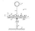
図1は、太陽14からの太陽光線12を利用して電気を作り出すための太陽電池装置10の一実施形態の前面図を示している。さらなる図として、図2は図1の実施形態の左側面図を示している。図1及び2に示されるように、太陽電池装置10は実質的に垂直なスタンド部材16、サポートスタンド部材18、及び複数の太陽集熱器20を備えていてもよい。該実質的に垂直なスタンド部材16は、地表面21に対して実質的に垂直な方向に延びる円形部材を含んでいてもよい。該垂直スタンド部材16は、太陽集熱器20の配向及び/又は方向を変えるために、地表面21に対して回転するように構成されていてもよい。他の実施形態では、実質的に垂直なスタンド部材16は固定されていてもよく、追跡機構がスタンド部材18及び取り付けられた複数の太陽集熱器20を、太陽を追跡する位置に向けるようにしてもよい。他の実施形態では、スタンド部材16は、他の形状、サイズ、配置、あるいは方向であってもよく、及び/又は様々な方向に動けるようになっていてもよい。正確に平行な配置又は正確に平行な配置から1°以内である、実質的に平行な配置でサポートスタンド部材18に取り付けられた太陽集熱器20を備えるサポートスタンド部材18は垂直スタンド部材16に枢動可能に取り付けられた長方形の部材を備えていてもよい。サポートスタンド部材18は、太陽集熱器20の配向及び/又は方向を変えるために、垂直スタンド部材16に対して枢動可能に構成されていてもよい。
FIG. 1 shows a front view of one embodiment of a
図1及び2に示される実施形態では、サポートスタンド部材18及び平行配置された太陽集熱器20双方の地表面21に対する角度23は0°であり、太陽14が太陽集熱器20の直上にあり、熱パイプ28の周囲の空気42は静止して動きがない。他の実施形態では、垂直スタンド部材16の周りにサポートスタンド部材18を回転させることにより、サポートスタンド部材18及び取り付けられた太陽集熱器20双方の地表面21に対する角度23は変化し、太陽14は地表面21に対して異なる位置にあり、及び/又は熱パイプ28の周囲の空気42は様々な角度に動く。垂直スタンド部材16を地表面21に対して回転させること、及び/又はサポートスタンド部材18を地表面21に対して傾けることにより、日中に太陽14が空を移動する間、太陽光線12の最大量を集める理想的な配向にこれらを位置させるように太陽集熱器20が向けられることに注意すべきである。
In the embodiment shown in FIGS. 1 and 2, the
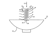
太陽集熱器20の一つの拡大図を示すために、図1Aは図1の実施形態の1A−1Aでの図を示し、図2Aは図2の2A−2Aでの図を示している。図1A及び2Aに示されるように、各太陽集熱器20は、反射面22、太陽電池24、ベースプレート26、熱パイプ28、及び複数の冷却フィン30を備えていてもよい。該反射面22は、太陽光線12を太陽電池24に向かわせるために湾曲していてもよい。該太陽電池24は太陽光線12を集めて、大規模な設備の一部である一つ又は複数の装置又はコンバーターに電気を提供するために太陽光線12からの熱を利用する。太陽電池24は、熱パイプ28に取り付けられたベースプレート26に取り付けられていてもよい。該ベースプレート26は、長方形、湾曲した形状又は他の型、形状、サイズ、配置、又は方向であってもよい。熱パイプ28はベースプレート26から実質的に垂直に延長されていてもよい。
To show one enlarged view of the
複数の冷却フィン30は、それぞれ熱パイプ28に対して非垂直第1角40で取り付けられていてもよい。冷却フィン30は、曲線、円形、楕円形、多角形、長方形、及び/又は他の型、形状、サイズであってもよい。10ないし20の冷却フィン30が各熱パイプ28に取り付けられてもよい。他の実施形態では、如何なる数の冷却フィン30が各々の熱パイプ28に取り付けられてもよい。該冷却フィン30は、銅、鉄、あるいは他の導体材料からなってもよい。該非垂直第1角40は、1ないし45°の範囲であってもよい。一実施形態では、該非垂直第1角40は、1ないし10°の範囲であってもよい。他の実施形態では、該非垂直第1角40は、10ないし20°の範囲であってもよい。さらに他の実施形態では、該非垂直第1角40は、20ないし30°の範囲であってもよい。さらに他の実施形態では、非垂直第1角40は、30ないし45°の範囲であってもよい。他の実施形態では、非垂直第1角40は、熱パイプ28に対して垂直ではない如何なる角度を含んでもよい。
The plurality of cooling
過剰な熱による太陽電池24の損傷を制限するため及び/又は避けるために、太陽電池24は、過剰な熱を熱パイプ28へ移動させるように構成されてもよい。図1Aの実施形態の熱パイプ28の1B−1Bでの断面図である図1Bに示されるように、熱パイプ28は、水又は他の液体といった、液体34を含む、中が空洞の内部室32を有する円形パイプ部材を備えていてもよい。該熱パイプ28は、太陽電池24の過剰な熱によって加熱され、熱パイプ28の室32内の液体34を蒸気36へ気化させるように構成されていてもよい。蒸気36は、伝導41を介して、蒸気36から熱パイプ28の表面38へ熱を移動させるように構成されていてもよい。加熱された熱パイプ28は、冷却フィン30による対流34を介して、熱パイプ28から熱パイプ28の外部の周囲の空気42へ熱を移動させるように構成されていてもよい。
In order to limit and / or avoid damaging the
冷却フィン30の非垂直第1角40は、熱の上昇の効果のため、各冷却フィン30において低点44から高点46へ流れる、加熱された周囲の空気42熱パイプ28から周囲の空気42への、対流熱の移動43の割合及び/又は総量を、熱パイプに垂直な既存の冷却フィンよりも増加させる。これは、太陽電池24からの過剰な熱の移動をより早く及び/又は多量にして、過剰な熱による太陽電池24の損傷を制限及び/又は回避を助ける。これは、サポートスタンド部材18及び平行配置である太陽集熱器20双方の地表面21に対する角度23が0°であり、太陽14が太陽集熱器20の直上にあり、熱パイプ28の周囲の空気42が静止して動かない状態である図1及び2の実施形態において特に重要である。フィンの間の加熱された空気が垂直に上昇することができない多くの既存の垂直な冷却フィンは、冷却フィンに沿った均一な高さのために、このような条件での熱パイプの冷却を助長しない。
The non-vertical
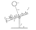
さらに、冷却フィン30の非垂直第1角40は、太陽集熱器20の配置、太陽14の位置、及び熱パイプ28の周囲の空気42が動いているかどうかにかかわらず、加熱された周囲の空気42熱パイプ28から周囲の空気42への、対流熱の移動43の割合及び/又は総量を、熱パイプに垂直な既存の冷却フィンよりも増加させる。例えば、サポートスタンド部材18及び平行配置である太陽集熱器20双方の地表面21に対する角度23が適度に傾き、太陽14が太陽集熱器20から適度に角度を有し、熱パイプ28の周囲の空気42が僅かに動いている状態である、図1の実施形態の左側面図を示す図3の実施形態では、熱パイプ28から周囲の空気42への熱の移動43はさらに増加する。
In addition, the non-vertical
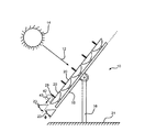
同様に、サポートスタンド部材18及び平行配置である太陽集熱器20双方の地表面21に対する角度23が実質的に傾き、太陽14が太陽集熱器20から実質的に角度を有し、熱パイプ28の周囲の空気42が実質的に動いている状態である、図1の実施形態の左側面図を示す図4の実施形態では、熱パイプ28から周囲の空気42への熱の移動43はさらに増加する。
Similarly, the
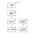
図5は太陽集熱器20から熱を移動させる方法の実施例148のフローチャートを示している。一ステップ150では、熱パイプ、少なくとも一つの冷却フィン30、及び太陽電池24を備える太陽集熱器20が提供される。該少なくとも一つの冷却フィン30は、非垂直第1角40で熱パイプ28に取り付けられる。該非垂直第1角40は実質的に1ないし45°の範囲、あるいは他の実施形態では、様々な角度であってもよい。該冷却フィン30は、曲線、円形、楕円形、多角形、長方形、及び/又は他の型、形状、サイズであってもよい。複数の冷却フィン30が熱パイプ28に取り付けられてもよい。該熱パイプ28は太陽電池24に取り付けられたベースプレート26から実質的に垂直に延長されていてもよい。
FIG. 5 shows a flowchart of an
他のステップ152では、太陽光線12は太陽電池24に反射されてもよい。さらなる他のステップ154では、太陽電池24からの過剰な熱が熱パイプ28に移動されてもよい。さらなる他のステップ156では、熱パイプ28内の液体34が蒸気36まで加熱されてもよい。さらなる他のステップ158では、熱が蒸気36から熱パイプ28の表面38へ移動されてもよい。さらなるステップ160では、熱パイプ28からの熱は対流を介して熱パイプ28の外部の周囲の空気42へ移動されてもよい。非垂直第1角である冷却フィン30の使用は、対流43の量を増加させる。対流プロセス43の間、該太陽集熱器20は地表面21に平行であってもよく、太陽14は太陽集熱器20の直上にあってもよく、熱パイプ28の周囲の空気42は動いていなくともよい。さらに他の実施形態では、熱パイプ28から熱パイプ28の周囲の空気42への対流43を介して、太陽集熱器20の配置、太陽14の位置、及び熱パイプ28の周囲の空気42が動くかどうかにかかわらず、熱が移動されてもよい。
In another
図6は、太陽集熱器20を製造する方法の実施形態270のフローチャートを示している。一ステップ272では、熱パイプ28及び複数の冷却フィン30が提供される。他のステップ274では、少なくとも一つの冷却フィン30が熱パイプ28に対して非垂直第1角40で取り付けられる。該少なくとも一つの冷却フィン30は、曲線、円形、楕円形、多角形、長方形、及び/又は他の型、形状、サイズであってもよい。複数の冷却フィン30が用いられてもよい。非垂直第1角40は、実質的に1ないし45°の範囲、あるいは他の実施形態では、様々な角度であってもよい。
FIG. 6 shows a flowchart of an
本開示の一又は複数の実施形態は、一又は複数の既存の太陽集熱器及び/又は方法に対する一又は複数の以下の優れた利点を提供する:熱パイプ28及び/又は太陽電池24の冷却の増進させる(例えば、熱の移動);太陽電池24の過剰な加熱による損傷及び/又はコストを低減させる;太陽集熱器20の配置、太陽14の位置、及び熱パイプ28の周囲の空気42が動いているかどうかにかかわらず、熱パイプ28から熱パイプ28の周囲の空気42への対流43を増加させる;及び/又は、一又は複数の既存の太陽集熱器及び/又は方法に対する一又は複数の優れた利点を有する。
One or more embodiments of the present disclosure provide one or more of the following significant advantages over one or more existing solar collectors and / or methods: cooling of
無論、上記の開示は本開示の例示的な実施形態に関するものであり、以下の請求の範囲において示されるように、本開示の精神及び範囲から逸脱せずに修正が行われることは理解されるべきである。 Of course, it will be understood that the above disclosure is directed to exemplary embodiments of the present disclosure and modifications may be made without departing from the spirit and scope of the present disclosure, as set forth in the following claims. Should.
Claims (12)
熱パイプ、少なくとも一つの冷却フィン、及び太陽電池を備える太陽集熱器を提供し、前記少なくとも一つの冷却フィンが熱パイプに対して非垂直第1角で取り付けられること;
太陽電池に太陽光線を反射すること;
太陽電池から熱パイプへ過剰な熱を移動させること;
対流を介して熱パイプから該熱パイプ外の周囲の空気へ熱を移動させること
を含む方法。 A method of transferring heat from a solar collector,
Providing a solar collector comprising a heat pipe, at least one cooling fin, and a solar cell, wherein the at least one cooling fin is mounted at a non-vertical first angle to the heat pipe;
Reflecting sunlight into the solar cell;
Transferring excess heat from solar cells to heat pipes;
Transferring heat from the heat pipe to the surrounding air outside the heat pipe via convection.
熱パイプ、及び少なくとも一つの冷却フィンを提供すること、及び
前記少なくとも一つの冷却フィンを熱パイプに対して非垂直第1角で取り付けること
を含む太陽集熱器の製造方法。 A solar collector manufacturing method comprising:
Providing a heat pipe and at least one cooling fin, and attaching the at least one cooling fin to the heat pipe at a non-vertical first corner.
Applications Claiming Priority (2)
| Application Number | Priority Date | Filing Date | Title |
|---|---|---|---|
| US11/763,965 US20080308152A1 (en) | 2007-06-15 | 2007-06-15 | Solar collector with angled cooling fins |
| PCT/US2008/064551 WO2008156962A2 (en) | 2007-06-15 | 2008-05-22 | Solar collector with angled cooling fins |
Publications (2)
| Publication Number | Publication Date |
|---|---|
| JP2010538192A true JP2010538192A (en) | 2010-12-09 |
| JP2010538192A5 JP2010538192A5 (en) | 2011-06-30 |
Family
ID=39925001
Family Applications (1)
| Application Number | Title | Priority Date | Filing Date |
|---|---|---|---|
| JP2010512245A Pending JP2010538192A (en) | 2007-06-15 | 2008-05-22 | Solar collector with angled cooling fins |
Country Status (4)
| Country | Link |
|---|---|
| US (1) | US20080308152A1 (en) |
| EP (1) | EP2167883A2 (en) |
| JP (1) | JP2010538192A (en) |
| WO (1) | WO2008156962A2 (en) |
Families Citing this family (13)
| Publication number | Priority date | Publication date | Assignee | Title |
|---|---|---|---|---|
| US8592673B2 (en) * | 2009-05-04 | 2013-11-26 | The Boeing Company | Enclosed, off-axis solar concentrator |
| US8490619B2 (en) * | 2009-11-20 | 2013-07-23 | International Business Machines Corporation | Solar energy alignment and collection system |
| US8026439B2 (en) | 2009-11-20 | 2011-09-27 | International Business Machines Corporation | Solar concentration system |
| US8940999B1 (en) | 2009-12-07 | 2015-01-27 | The Boeing Company | Modular off-axis solar concentrator |
| US9127859B2 (en) * | 2010-01-13 | 2015-09-08 | International Business Machines Corporation | Multi-point cooling system for a solar concentrator |
| US9175882B2 (en) * | 2010-03-18 | 2015-11-03 | The Boeing Company | Solar energy system with wind vane |
| CN201788986U (en) * | 2010-05-21 | 2011-04-06 | 宇威光电股份有限公司 | Solar battery device |
| CN108869210A (en) | 2010-09-16 | 2018-11-23 | 威尔逊太阳能公司 | Use the centralized solar electrical energy generation system of solar receiver |
| CN101963363B (en) * | 2010-10-15 | 2011-12-07 | 陆守祥 | Radiant tube heat exchanger |
| US9054251B1 (en) | 2011-07-28 | 2015-06-09 | The Boeing Company | Solar collector array |
| CN112797649A (en) | 2012-03-21 | 2021-05-14 | 威尔逊太阳能公司 | Solar receiver, power generation system and fluid flow control device |
| DE102012017211B4 (en) * | 2012-08-31 | 2015-05-21 | Odilo Reutter | Building module and method for using thermal energy |
| FR3074271B1 (en) * | 2017-11-30 | 2019-11-15 | Commissariat A L'energie Atomique Et Aux Energies Alternatives | ABSORBER COMPRISING THE ABSORBENT OF INCIDENTAL RADIATION AND SOLAR SENSOR COMPRISING THE ABSORBER |
Citations (3)
| Publication number | Priority date | Publication date | Assignee | Title |
|---|---|---|---|---|
| JP2000283670A (en) * | 1999-03-30 | 2000-10-13 | Furukawa Electric Co Ltd:The | Heat sink |
| JP2003287376A (en) * | 2002-03-28 | 2003-10-10 | Meidensha Corp | Heat sink and element cooler composed of this heat sink |
| US20060243319A1 (en) * | 2005-04-29 | 2006-11-02 | Arizona Public Service Company | Clustered solar-energy conversion array and method therefor |
Family Cites Families (8)
| Publication number | Priority date | Publication date | Assignee | Title |
|---|---|---|---|---|
| JPS6247166Y2 (en) * | 1978-06-16 | 1987-12-25 | ||
| NL7808774A (en) * | 1978-08-25 | 1980-02-27 | Philips Nv | SOLAR COLLECTOR. |
| JP3094780B2 (en) * | 1994-04-05 | 2000-10-03 | 株式会社日立製作所 | Electronic equipment |
| US5660644A (en) * | 1995-06-19 | 1997-08-26 | Rockwell International Corporation | Photovoltaic concentrator system |
| US6384320B1 (en) * | 2000-10-13 | 2002-05-07 | Leon Lung-Chen Chen | Solar compound concentrator of electric power generation system for residential homes |
| WO2007053939A1 (en) * | 2005-11-09 | 2007-05-18 | Tir Technology Lp. | Passive thermal management system |
| IL176619A0 (en) * | 2006-06-29 | 2006-10-31 | Zalman Schwartzman | A photovoltaic array for concentrated solar energy generator |
| US20080115915A1 (en) * | 2006-11-16 | 2008-05-22 | Ryan Chen | Heat sink |
-
2007
- 2007-06-15 US US11/763,965 patent/US20080308152A1/en not_active Abandoned
-
2008
- 2008-05-22 JP JP2010512245A patent/JP2010538192A/en active Pending
- 2008-05-22 WO PCT/US2008/064551 patent/WO2008156962A2/en active Application Filing
- 2008-05-22 EP EP08769625A patent/EP2167883A2/en not_active Ceased
Patent Citations (3)
| Publication number | Priority date | Publication date | Assignee | Title |
|---|---|---|---|---|
| JP2000283670A (en) * | 1999-03-30 | 2000-10-13 | Furukawa Electric Co Ltd:The | Heat sink |
| JP2003287376A (en) * | 2002-03-28 | 2003-10-10 | Meidensha Corp | Heat sink and element cooler composed of this heat sink |
| US20060243319A1 (en) * | 2005-04-29 | 2006-11-02 | Arizona Public Service Company | Clustered solar-energy conversion array and method therefor |
Also Published As
| Publication number | Publication date |
|---|---|
| US20080308152A1 (en) | 2008-12-18 |
| WO2008156962A2 (en) | 2008-12-24 |
| EP2167883A2 (en) | 2010-03-31 |
| WO2008156962A3 (en) | 2010-07-01 |
Similar Documents
| Publication | Publication Date | Title |
|---|---|---|
| JP2010538192A (en) | Solar collector with angled cooling fins | |
| Barone et al. | Solar thermal collectors | |
| JP2004527723A5 (en) | ||
| US20130098354A1 (en) | Solar collectors | |
| ES2425996B1 (en) | Solar plate receiver | |
| US10431705B2 (en) | Cooling system for high performance solar concentrators | |
| JP2013517626A (en) | Multi-point cooling system for solar concentrator | |
| US20160380583A1 (en) | Solar Panel Efficacy-Method and Device | |
| WO2015089273A1 (en) | Advanced cavity receivers for parabolic solar troughs | |
| KR102074563B1 (en) | Enclosure with directionally-placed power transmission conductors, and method of placement | |
| EP2834575A2 (en) | Method and apparatus for electricity production by means of solar thermal transformation | |
| EP2444664A1 (en) | Tower for solar concentration plant with natural draught cooling | |
| CN103629827B (en) | Large-capacity well type solar heat collection-storage device | |
| JP5662098B2 (en) | Cold / hot water production equipment | |
| US20160268969A1 (en) | Dish receiver system for solar power generation | |
| TWI360635B (en) | ||
| CN207977938U (en) | A kind of parabolic solar solar panel based on Fresnel condenser | |
| JP2014524559A (en) | Solar radiation receiver | |
| KR102618308B1 (en) | Heat saving device using fresnel lens | |
| JP2018091554A (en) | Heat storage device | |
| WO2018156529A1 (en) | Systems and methods of generating solar energy and dry cooling | |
| RU2194927C1 (en) | Solar collector | |
| RU2734667C1 (en) | Method of heating water with solar radiation | |
| TW201303235A (en) | Solar heat transfer apparatus | |
| TWM432146U (en) | Disk type concentrating solar photoelectric structure |
Legal Events
| Date | Code | Title | Description |
|---|---|---|---|
| A521 | Written amendment |
Free format text: JAPANESE INTERMEDIATE CODE: A523 Effective date: 20110511 |
|
| A621 | Written request for application examination |
Free format text: JAPANESE INTERMEDIATE CODE: A621 Effective date: 20110511 Free format text: JAPANESE INTERMEDIATE CODE: A621 Effective date: 20110511 |
|
| A977 | Report on retrieval |
Free format text: JAPANESE INTERMEDIATE CODE: A971007 Effective date: 20111104 |
|
| A131 | Notification of reasons for refusal |
Free format text: JAPANESE INTERMEDIATE CODE: A131 Effective date: 20111129 |
|
| A02 | Decision of refusal |
Free format text: JAPANESE INTERMEDIATE CODE: A02 Effective date: 20120508 |