JP2010537689A - Pulse aerosol generation method - Google Patents
Pulse aerosol generation method Download PDFInfo
- Publication number
- JP2010537689A JP2010537689A JP2010522471A JP2010522471A JP2010537689A JP 2010537689 A JP2010537689 A JP 2010537689A JP 2010522471 A JP2010522471 A JP 2010522471A JP 2010522471 A JP2010522471 A JP 2010522471A JP 2010537689 A JP2010537689 A JP 2010537689A
- Authority
- JP
- Japan
- Prior art keywords
- liquid
- capillary
- capillary passage
- compartment
- passage
- Prior art date
- Legal status (The legal status is an assumption and is not a legal conclusion. Google has not performed a legal analysis and makes no representation as to the accuracy of the status listed.)
- Pending
Links
Images


Classifications
-
- A—HUMAN NECESSITIES
- A61—MEDICAL OR VETERINARY SCIENCE; HYGIENE
- A61L—METHODS OR APPARATUS FOR STERILISING MATERIALS OR OBJECTS IN GENERAL; DISINFECTION, STERILISATION OR DEODORISATION OF AIR; CHEMICAL ASPECTS OF BANDAGES, DRESSINGS, ABSORBENT PADS OR SURGICAL ARTICLES; MATERIALS FOR BANDAGES, DRESSINGS, ABSORBENT PADS OR SURGICAL ARTICLES
- A61L9/00—Disinfection, sterilisation or deodorisation of air
- A61L9/015—Disinfection, sterilisation or deodorisation of air using gaseous or vaporous substances, e.g. ozone
- A61L9/02—Disinfection, sterilisation or deodorisation of air using gaseous or vaporous substances, e.g. ozone using substances evaporated in the air by heating or combustion
- A61L9/03—Apparatus therefor
- A61L9/037—Apparatus therefor comprising a wick
-
- A—HUMAN NECESSITIES
- A61—MEDICAL OR VETERINARY SCIENCE; HYGIENE
- A61L—METHODS OR APPARATUS FOR STERILISING MATERIALS OR OBJECTS IN GENERAL; DISINFECTION, STERILISATION OR DEODORISATION OF AIR; CHEMICAL ASPECTS OF BANDAGES, DRESSINGS, ABSORBENT PADS OR SURGICAL ARTICLES; MATERIALS FOR BANDAGES, DRESSINGS, ABSORBENT PADS OR SURGICAL ARTICLES
- A61L9/00—Disinfection, sterilisation or deodorisation of air
- A61L9/14—Disinfection, sterilisation or deodorisation of air using sprayed or atomised substances including air-liquid contact processes
-
- F—MECHANICAL ENGINEERING; LIGHTING; HEATING; WEAPONS; BLASTING
- F24—HEATING; RANGES; VENTILATING
- F24F—AIR-CONDITIONING; AIR-HUMIDIFICATION; VENTILATION; USE OF AIR CURRENTS FOR SCREENING
- F24F6/00—Air-humidification, e.g. cooling by humidification
- F24F6/02—Air-humidification, e.g. cooling by humidification by evaporation of water in the air
- F24F6/025—Air-humidification, e.g. cooling by humidification by evaporation of water in the air using electrical heating means
-
- F—MECHANICAL ENGINEERING; LIGHTING; HEATING; WEAPONS; BLASTING
- F24—HEATING; RANGES; VENTILATING
- F24F—AIR-CONDITIONING; AIR-HUMIDIFICATION; VENTILATION; USE OF AIR CURRENTS FOR SCREENING
- F24F8/00—Treatment, e.g. purification, of air supplied to human living or working spaces otherwise than by heating, cooling, humidifying or drying
- F24F8/50—Treatment, e.g. purification, of air supplied to human living or working spaces otherwise than by heating, cooling, humidifying or drying by odorisation
Abstract
エーロゾル発生器は、毛細管作用のみを通じて毛細管通路40に液体香料物質を繰返し供給し、かつ液体香料物質が少なくとも部分的に揮発して毛細管通路40の出口45から押し出されるように毛細管通路40を加熱することにより、エーロゾル化香料物質を定期的に形成する。芯20は、毛細管作用によって毛細管通路40の入口に液体香料物質を給送する。そのようなエーロゾル化香料物質を発生させるための装置及び方法、並びに加熱する方法を開示する。
【選択図】図1The aerosol generator repeatedly supplies liquid perfume material to the capillary passage 40 through capillary action only, and heats the capillary passage 40 so that the liquid perfume material is at least partially volatilized and pushed out of the outlet 45 of the capillary passage 40. This periodically forms an aerosolized perfume material. The wick 20 feeds the liquid perfume material to the inlet of the capillary passage 40 by capillary action. An apparatus and method for generating such aerosolized perfume material and a method of heating are disclosed.
[Selection] Figure 1
Description
提供するものは、入口及び出口を有する毛細管通路と、毛細管作用のみを通じて毛細管通路の入口に液体香料物質を供給するように作動可能な液体供給部と、毛細管通路の出口から液体香料物質が押し出されて液体香料物質のエーロゾルを形成するように、毛細管通路に沿って配置された加熱器にわたって電圧を印加して毛細管通路において液体香料物質を少なくとも部分的に揮発させるのに十分な温度まで毛細管通路における液体香料物質を加熱するようになった電源とを含むエーロゾル化液体香料物質を発生させるための空気清浄器である。 What is provided is a capillary passage having an inlet and an outlet, a liquid supply operable to supply liquid fragrance material to the inlet of the capillary passage only through capillary action, and liquid fragrance material is extruded from the outlet of the capillary passage. Voltage in a capillary passage to a temperature sufficient to at least partially volatilize the liquid fragrance material in the capillary passage by applying a voltage across a heater disposed along the capillary passage so as to form an aerosol of the liquid fragrance material. An air purifier for generating an aerosolized liquid fragrance material including a power source adapted to heat the liquid fragrance material.
更に提供するものは、入口及び出口を有する毛細管通路内に毛細管作用のみを通じて液体香料物質を吸引する段階と、毛細管通路の出口から香料物質が押し出されて香料物質のエーロゾルを形成するように、毛細管通路に沿って配置された加熱器にわたって電圧を周期的に印加し、液体香料物質を少なくとも部分的に揮発させるのに十分な温度まで毛細管通路における液体香料物質を加熱する段階とを含むエーロゾル化香料物質をパルス式に発生させる方法である。 Further provided is the step of aspirating the liquid perfume material only through capillary action into a capillary passage having an inlet and an outlet, and the capillary tube so that the perfume material is extruded from the outlet of the capillary passage to form an aerosol of the perfume material. Applying a periodic voltage across a heater disposed along the passage to heat the liquid perfume material in the capillary passage to a temperature sufficient to at least partially volatilize the liquid perfume material. This is a method of generating a substance in a pulsed manner.
別の実施形態では、液体のエーロゾルを生成する方法を提供する。本方法は、液体供給部から毛細管通路の区画内に毛細管作用を通じて液体を吸引することによってその区画に沿って液体を配置する段階と、電力サイクル中に毛細管作用を通じた液体の吸引が中断され、かつ各電力サイクルの終了時に区画に沿って配置された液体が加熱された区画から排出されるように、区画に沿って配置された実質的に全ての液体を揮発させるのに各電力サイクルの熱が十分であるような熱を区画の少なくとも一部分に沿って電力サイクルに従って繰返し印加する段階と、電力サイクルと電力サイクルの間に毛細管作用を通じた液体の吸引を再開して区画を補充するように電力サイクルを時間的に十分に離間させる段階とを含む。 In another embodiment, a method for producing a liquid aerosol is provided. The method includes disposing the liquid along the compartment by aspirating the liquid through the capillary action into the compartment of the capillary passage from the liquid supply, and interrupting the suction of the liquid through the capillary action during the power cycle, And the heat of each power cycle to volatilize substantially all of the liquid disposed along the compartment so that the liquid disposed along the compartment is drained from the heated compartment at the end of each power cycle. Repeatedly applying heat such that is sufficient along the power cycle along at least a portion of the compartment, and resuming liquid aspiration through capillary action between the power cycles to replenish the compartment. Separating the cycles sufficiently in time.
更に別の実施形態では、エーロゾル化液体材料を発生させるエーロゾル発生器を提供する。エーロゾル発生器は、入口、出口、及び加熱されるように作動可能であって入口と出口の間の通路に沿った区画を有する毛細管通路と、毛細管作用を通じて毛細管通路の区画内に吸引されるように毛細管通路の入口に液体材料を供給する液体供給部と、毛細管通路の区画の少なくとも一部分に沿って電力サイクルに従って熱を繰返し印加し、加熱された区画に配置された液体材料を揮発させ、そのために電力サイクル中に毛細管作用を通じた液体の吸引が中断され、かつ各電力サイクルの終了時に区画に沿って配置された液体が加熱された区画から排出されるように作動可能な電源とを含み、電力サイクルは、電力サイクルと電力サイクルの間に毛細管作用を通じた液体の吸引を再開して区画を補充するように時間的に十分に離間している。 In yet another embodiment, an aerosol generator for generating an aerosolized liquid material is provided. The aerosol generator is aspirated into the compartment of the capillary passage through a capillary action having an inlet, an outlet and a capillary passage operable to be heated and having a compartment along the passage between the inlet and the outlet. A liquid supply for supplying the liquid material to the inlet of the capillary passage, and repeatedly applying heat according to a power cycle along at least a portion of the capillary passage compartment to volatilize the liquid material disposed in the heated compartment, thereby A power source operable to interrupt liquid aspiration through capillary action during power cycles and to dispose of liquid disposed along the compartments from the heated compartment at the end of each power cycle; The power cycles are sufficiently spaced in time to resume liquid aspiration through capillary action and replenish the compartment between power cycles.
提供するものは、外気と混ぜられるエーロゾル化香料物質を発生させるための空気清浄器である。空気清浄器は、入口及び出口を有する毛細管通路と、毛細管作用のみを通じて毛細管通路の入口に液体香料物質を供給するように作動可能な液体供給部と、毛細管通路の出口から香料物質が押し出され、外気と混合してエーロゾルを形成するように、毛細管通路における液体香料物質を少なくとも部分的に揮発させるのに十分な温度まで毛細管通路における液体香料物質を加熱するために毛細管通路に沿って配置された加熱器にわたって電圧を印加するようになった電源とを含む。 What is provided is an air purifier for generating an aerosolized perfume material that is mixed with ambient air. The air purifier has a capillary passage having an inlet and an outlet, a liquid supply operable to supply liquid fragrance material to the inlet of the capillary passage only through capillary action, and the fragrance material is extruded from the outlet of the capillary passage, Arranged along the capillary passage to heat the liquid fragrance material in the capillary passage to a temperature sufficient to at least partially volatilize the liquid fragrance material in the capillary passage so as to mix with the outside air to form an aerosol And a power supply adapted to apply a voltage across the heater.
好ましくは、毛細管通路は、0.01から10mm、好ましくは、0.05から1mm、より好ましくは、0.05から0.4mm、より好ましくは、約0.05mmの内径を有する。代替的に、毛細管通路は、好ましくは、8x10⁻⁵から80mm2、好ましくは、0.002から0.8mm2、より好ましくは、0.002から0.05mm2、より好ましくは、約0.002mm2の内部断面積を有する。毛細管通路は、任意的に、毛細管通路の出口に減少した直径又は狭いオリフィスを有することができる。例えば、内径が約0.15mmの毛細管通路に対して、出口における狭いオリフィスは、約0.05mmの内径を有することができる。 Preferably, the capillary passage has an inner diameter of 0.01 to 10 mm, preferably 0.05 to 1 mm, more preferably 0.05 to 0.4 mm, more preferably about 0.05 mm. Alternatively, the capillary passage is preferably 8 × 10 −5 to 80 mm 2 , preferably 0.002 to 0.8 mm 2 , more preferably 0.002 to 0.05 mm 2 , more preferably about 0. It has an internal cross-sectional area of 002 mm 2 . The capillary passage can optionally have a reduced diameter or narrow orifice at the outlet of the capillary passage. For example, for a capillary passage having an inner diameter of about 0.15 mm, the narrow orifice at the outlet can have an inner diameter of about 0.05 mm.
いかなる特定理論にも制限されることは望まないが、毛細管通路の出口で減少した直径(狭いオリフィス)は、液体及び/又は揮発香料物質を毛細管通路出口の外に追い出す駆動力を提供する液体香料物質の加熱及び少なくとも部分的な揮発によって毛細管通路中に生成された高い圧力の結果として、毛細管通路における液体香料物質の粗い液滴がより小さい液滴に分解される流体剪断機構によってエーロゾルを生成するものと考えられている。すなわち、液体香料物質は、液体香料物質の加熱が、毛細管通路の出口の外に液体香料物質を追い出す圧力を毛細管通路中にもたらすので、毛細管通路の直径の減少した出口を通過することによってエーロゾル化することができる。 While not wishing to be limited to any particular theory, the reduced diameter (narrow orifice) at the outlet of the capillary passage provides a driving force to drive liquid and / or volatile perfume material out of the capillary passage outlet. As a result of the high pressure created in the capillary passage by heating and at least partial volatilization of the material, an aerosol is generated by a fluid shear mechanism in which coarse droplets of liquid perfume material in the capillary passage are broken down into smaller droplets It is considered a thing. That is, the liquid perfume material is aerosolized by passing through the outlet of reduced capillary passage diameter, as heating of the liquid perfume material causes pressure in the capillary passage to expel the liquid perfume material out of the outlet of the capillary passage. can do.
しかし、殆どの用途では、毛細管通路は、好ましくは、狭窄先端がない「直線チューブ」構成を含む。
毛細管通路は、約10から40mm、例えば、約25mmの長さを有することができる。毛細管通路は、好ましくは、チューブの長さに沿って直流又は交流通路のために取り付けられた電気リードを通じて加熱器として機能する例えば304ステンレス鋼のようなステンレス鋼毛細管の内部である。すなわち、ステンレス鋼チューブは、抵抗加熱によって加熱される。ステンレス鋼チューブは、好ましくは、断面が円形である。チューブは、様々なゲージの皮下注射針とすることができる。例えば、32ゲージの針は、0.11mmの内径、26ゲージの針は、0.26mmの内径を有する。
しかし、毛細管は、抵抗加熱され、一方で毛細管通路が受ける作動温度において必要な構造的一体性を保持し、かつ液体香料物質と十分に非反応性であるあらゆる導電材料とすることができる。そのような材料は、以下に限定されるものではないが、ステンレス鋼、INCONEL、金属複合物、又は他の金属及び合金を含む。
However, for most applications, the capillary passage preferably includes a “straight tube” configuration without a constricted tip.
The capillary passage can have a length of about 10 to 40 mm, for example about 25 mm. The capillary passage is preferably inside a stainless steel capillary, such as 304 stainless steel, which acts as a heater through electrical leads attached for direct current or alternating current passage along the length of the tube. That is, the stainless steel tube is heated by resistance heating. The stainless steel tube is preferably circular in cross section. The tube can be a hypodermic needle of various gauges. For example, a 32 gauge needle has an inner diameter of 0.11 mm and a 26 gauge needle has an inner diameter of 0.26 mm.
However, the capillary can be any conductive material that is resistively heated while retaining the necessary structural integrity at the operating temperature experienced by the capillary passage and is sufficiently non-reactive with the liquid perfume material. Such materials include, but are not limited to, stainless steel, INCONEL, metal composites, or other metals and alloys.
付加的な実施形態では、毛細管通路は、例えばガラスチューブのような非金属チューブの内部とすることができる。そのような実施形態では、加熱器、すなわち、例えば、ステンレス鋼、NICHROME、又は白金ワイヤのような抵抗加熱が可能な導電性金属は、ガラスチューブに沿って配置される。ガラスチューブに沿って配置された加熱器が加熱されると、毛細管通路における液体香料物質は、毛細管通路において液体香料物質を少なくとも部分的に揮発させるのに十分な温度まで加熱される。電気リードは、加熱器を電源に接続することができる。 In additional embodiments, the capillary passage may be inside a non-metallic tube, such as a glass tube. In such an embodiment, a heater, i.e., a conductive metal capable of resistance heating, such as stainless steel, NICHROME, or platinum wire, is placed along the glass tube. When a heater disposed along the glass tube is heated, the liquid perfume material in the capillary passage is heated to a temperature sufficient to at least partially volatilize the liquid perfume material in the capillary passage. The electrical lead can connect the heater to a power source.
電圧を印加する電源は、電圧供給源と2つの電気リードを含むことができる。電圧供給源は、直流バッテリとすることができる。しかし、交流の使用も有効とすることができると考えられる。毛細管通路がステンレス鋼チューブの内部である用途の場合には、電気リードは、好ましくは、チューブを抵抗加熱する電力を供給するためにチューブに沿って離間した位置に取り付けられる。
電源は、好ましくは、電気リードを通じて毛細管加熱器に電力のパルスを送出する。選択された電圧は、各パルスにおいて毛細管通路を加熱するのに使用されることになるエネルギの量を決める。電圧供給源から毛細管通路に移送されるエネルギは、オームの法則によって支配される。
V(電圧)=I(電流)・R(抵抗) (1)
電力=V・I=V2/R (2)
The power supply for applying the voltage can include a voltage supply and two electrical leads. The voltage supply source may be a direct current battery. However, it is thought that the use of alternating current can also be effective. For applications where the capillary passage is inside a stainless steel tube, the electrical leads are preferably mounted at spaced locations along the tube to provide power to resistively heat the tube.
The power supply preferably delivers a pulse of power to the capillary heater through an electrical lead. The selected voltage determines the amount of energy that will be used to heat the capillary passage in each pulse. The energy transferred from the voltage source to the capillary passage is governed by Ohm's law.
V (voltage) = I (current) · R (resistance) (1)
Electric power = V · I = V 2 / R (2)
好ましくは、液体供給部は、通気される。液体供給部は、毛細管作用のみによって液体香料物質を液体供給部から毛細管通路の入口まで送出する芯を含むことができる。好ましくは、芯材料は、多数の孔隙を含有し、これらの孔隙は、毛細管通路として作用し、これは、液体香料物質をそれらの中に、次に、毛細管通路の入口の中に吸引させる。 Preferably, the liquid supply part is ventilated. The liquid supply can include a wick that delivers liquid perfume material from the liquid supply to the inlet of the capillary passage only by capillary action. Preferably, the core material contains a number of pores, which act as capillary passages, which allow liquid perfume material to be drawn into them and then into the inlets of the capillary passages.
芯は、様々な材料で作ることができるが、多孔性プラスチック芯が好ましい。多孔性プラスチック芯の例は、超高分子量高密度ポリエチレン(HDPE)で構成された芯である。そのような芯は、一般的に、粒子形態のHDPEの配合物で作られ、配合物は、芯のターゲット孔隙特性を満足するように開発される。好ましくは、ポリマーの溶解度パラメータは、液体香料物質のそれとは大幅に異なり、これは、芯の孔隙サイズ及び空隙率の変化をもたらす可能性がある芯の膨潤又は他の変化を防止する。 The core can be made of a variety of materials, but a porous plastic core is preferred. An example of a porous plastic core is a core made of ultra high molecular weight high density polyethylene (HDPE). Such wicks are generally made of a blend of HDPE in particulate form, and the blend is developed to meet the target pore characteristics of the wick. Preferably, the solubility parameter of the polymer is significantly different from that of the liquid perfume material, which prevents wick swelling or other changes that can lead to changes in wick pore size and porosity.
液体香料物質は、エーロゾル化香料物質を発生させるために毛細管通路に送出することができるあらゆる適切な液体香料物質とすることができる。例えば、液体香料物質は、市販の空気清浄器に使用するのに適するあらゆる市販の液体香料物質とすることができる。液体香料物質は、好ましくは、水性ベース、例えば、メタノールのようなアルコールベース、又はプロピレングリコールベースである。
例えば、毛細管通路の内径及び/又は毛細管通路を形成する材料の伝熱特性のような空気清浄器のパラメータの操作は、加熱器温度と質量平均粒子径を制御するように選択することができる。更に、液体香料物質の選択は、加熱器温度とエーロゾル化材料の質量平均粒子径に影響を与える可能性がある。
The liquid perfume material can be any suitable liquid perfume material that can be delivered to the capillary passage to generate an aerosolized perfume material. For example, the liquid fragrance material can be any commercially available liquid fragrance material suitable for use in a commercial air purifier. The liquid perfume material is preferably an aqueous base, for example an alcohol base such as methanol, or a propylene glycol base.
For example, manipulation of air purifier parameters, such as the inner diameter of the capillary passage and / or the heat transfer characteristics of the material forming the capillary passage, can be selected to control the heater temperature and mass average particle size. Furthermore, the choice of liquid perfume material can affect the heater temperature and the mass average particle size of the aerosolized material.
更に提供するものは、毛細管作用のみを通じて毛細管通路の入口内に液体香料物質を吸引する段階と、毛細管通路の出口から香料物質が押し出されるように液体香料物質を少なくとも部分的に揮発させるのに十分な温度まで毛細管通路における液体香料物質を加熱するために、毛細管通路に沿って配置された加熱器にわたって電圧を周期的に印加する段階とを含むエーロゾル化香料物質を発生させる方法である。
毛細管通路に沿って配置された加熱器にわたって電圧が印加され、かつ毛細管通路の出口から香料物質が押し出された後に、毛細管通路は、冷えて、毛細管作用のみを通じて再度補充される。毛細管通路の補充時間は、毛細管通路の長さ及び直径、並びに芯及び液体香料物質の特性の関数である。例えば、長さが25mmで内径が0.15mmの毛細管通路の場合、補充を10秒未満で行うことができる。すなわち、毛細管通路が冷えてより多くの液体香料物質を吸引した後に、毛細管通路の出口から香料物質が押し出されるように液体香料物質を少なくとも部分的に揮発させるのに十分な温度まで毛細管通路における液体香料物質を加熱するために、加熱器は、毛細管通路に沿って配置された加熱器にわたって電圧を周期的に印加することを達成する制御回路によって再度作動される。従って、エーロゾル化香料物質の繰返しパルス式発生の方法は、香料物質をエーロゾル化する段階、毛細管通路を冷却する段階、補充を繰り返す段階、及びエーロゾル化する段階を含む。
Further provided is the step of aspirating the liquid fragrance material into the capillary passage inlet only through capillary action and sufficient to at least partially volatilize the liquid fragrance material such that the fragrance material is pushed out of the capillary passage outlet Applying a periodic voltage across a heater disposed along the capillary passage to heat the liquid fragrance material in the capillary passage to a certain temperature.
After a voltage is applied across a heater located along the capillary passage and the perfume material is pushed out of the outlet of the capillary passage, the capillary passage cools and is refilled only through capillary action. The replenishment time of the capillary passage is a function of the length and diameter of the capillary passage and the properties of the wick and liquid perfume material. For example, in the case of a capillary passage having a length of 25 mm and an inner diameter of 0.15 mm, replenishment can be performed in less than 10 seconds. That is, the liquid in the capillary passage to a temperature sufficient to at least partially volatilize the liquid fragrance material so that the fragrance material is pushed out from the outlet of the capillary passage after the capillary passage cools and sucks more liquid fragrance material In order to heat the perfume material, the heater is again actuated by a control circuit that accomplishes the periodic application of voltage across the heater disposed along the capillary passage. Thus, a method for repeated pulsed generation of an aerosolized perfume material includes the steps of aerosolizing the perfume material, cooling the capillary passage, repeating replenishment, and aerosolizing.
エーロゾル化香料物質の繰返しパルス式発生の頻度は、毛細管通路補充時間によって制限される。すなわち、毛細管通路の長さ及び直径と液体香料物質とに応じて、エーロゾル化香料物質は、2から100秒ごとほど頻繁に、場合によっては少なくとも1分に一度に、又は例えば1時間に少なくとも一度又は1日に少なくとも一度のようなより低い頻度で発生させることができる。毛細管作用のみによって毛細管通路を実質的に補充するために、毛細管通路内に含有される実質的に全ての液体香料物質は、毛細管通路から押し出され、従って、実質的に乾燥した毛細管通路をもたらす。 The frequency of repeated pulsed generation of aerosolized perfume material is limited by the capillary passage refill time. That is, depending on the length and diameter of the capillary passage and the liquid fragrance material, the aerosolized fragrance material is frequently as frequently as every 2 to 100 seconds, sometimes at least once a minute, or at least once an hour, for example. Or it can occur less frequently, such as at least once a day. In order to substantially replenish the capillary passage only by capillary action, substantially all of the liquid perfume material contained within the capillary passage is pushed out of the capillary passage, thus providing a substantially dry capillary passage.
空気清浄器は、電源にバッテリを用いて小規模のデバイスで実施することができる。代替的に、電源は、ACコンセントのような交流(AC)供給源とし、空気清浄器は、必要に応じて、ACを加熱器に供給される直流に変換する変換器を含むことができる。空気清浄器は、毛細管通路を先導する毛細管の後に液体香料物質が少なくとも部分的に揮発するように、時限式加熱サイクルで電源から加熱器まで電力を送出可能な制御回路によって作動させることができる。すなわち、制御回路は、香料物質を揮発させるために加熱器にわたる電圧の印加を制御する。特に、制御回路は、香料物質を揮発させるために加熱器にわたる電圧印加の頻度を制御することができる。制御回路は、香料物質の繰返しパルス式エーロゾル化の頻度を自動的に制御することができる。代替的に、エーロゾル化香料物質の繰返しパルス式発生の頻度は、制御回路で事前設定又は手動設定することができ、制御回路は、事前設定又は手動で選択された頻度に従ってエーロゾル化香料物質の発生を制御する。必要に応じて、制御回路/電源は、1次及び/又は2次セル、好ましくは1次セル、超コンデンサを含むコンデンサ、電荷ポンプ、及びその組合せを含むことができる。超コンデンサを使用すると、バッテリ寿命が延び、及び/又はより少ない又はより小さいバッテリの使用を可能にすることができる。 Air purifiers can be implemented in small devices using batteries as power sources. Alternatively, the power source may be an alternating current (AC) source, such as an AC outlet, and the air cleaner may include a converter that converts AC to direct current supplied to the heater, if desired. The air purifier can be activated by a control circuit capable of delivering power from the power source to the heater in a timed heating cycle so that the liquid perfume material volatizes at least partially after the capillary leading the capillary passage. That is, the control circuit controls the application of voltage across the heater to volatilize the perfume material. In particular, the control circuit can control the frequency of voltage application across the heater to volatilize the perfume material. The control circuit can automatically control the frequency of the repetitive pulsed aerosolization of the perfume material. Alternatively, the frequency of repetitively pulsed generation of aerosolized fragrance material can be preset or manually set in a control circuit, which can generate aerosolized fragrance material according to a preset or manually selected frequency. To control. If desired, the control circuit / power supply can include primary and / or secondary cells, preferably primary cells, capacitors including supercapacitors, charge pumps, and combinations thereof. Using supercapacitors can increase battery life and / or allow the use of fewer or smaller batteries.
図1は、空気清浄器の例示的実施形態を表している。液体供給部10は、液体香料物質を芯20に供給し、芯20は、好ましくはステンレス鋼でありかつ出口45を有する毛細管40の入口に液体香料物質を供給する。毛細管40に取り付けられているのは、毛細管40に電圧を供給するための電気リード50である。電気リード50は、毛細管40に供給される電力を調節する制御回路60に接続される。毛細管40への電力のパルス式送出により、揮発化液体香料物質は、毛細管40の出口45から周期的に押し出されてエーロゾルを形成する。
FIG. 1 represents an exemplary embodiment of an air purifier. The
図2は、毛細管(図2の「毛細管」)のための加熱器と電気リード(「Cap1ry+」及び「Cap1ry−」)とを含む例示的制御回路の回路図である。これらの電気リードは、電気リードを通じてパルス電力によって液体香料物質が加熱されるステンレス鋼毛細管に沿って離間した位置に取り付けることができる。AAセルのような1つ又はそれよりも多くのバッテリによって制御回路に電力供給することができるが、図2の制御回路は、1つのバッテリBによって電力供給されている。制御回路は、好ましくは、マスター電源スイッチSW1、並びにMicrochip製のPIC12F675のようなマイクロコントローラU1を含む。図2に示すマイクロコントローラU1は、利用されない出力端子2、3、5、7を有し、それらは、制御回路の複雑さに応じて利用することができる。空気清浄器の加熱器に電圧を印加するタイミングは、好ましくは、マイクロコントローラの内部クロックによって設定される。調節可能なタイミングの場合、エーロゾルを送出する時間間隔を設定するために1回又はそれよりも多くの回数だけプッシュボタンスイッチを押すことができる。設定時間間隔のような情報を表示する表示LEDも、マイクロコントローラによって制御することができる。マイクロコントローラの制御の下で毛細管加熱器に対する電力を切り換えるために、例えば、Si4876のような電界効果トランジスタQ1が使用される。バッテリによってエネルギを直接加熱器に送出することができるが、図2の制御回路は、エネルギパルスとして毛細管加熱器にエネルギを供給し、すなわち、毛細管通路における液体香料物質をエーロゾル化するのに十分なエネルギのパルスを加熱器に放出する超コンデンサC1を含む電源を有する。マイクロコントローラU1は、超コンデンサC1が補充するのに必要な時間よりも持続時間が短いタイミングサイクルに対して予めプログラムされるか又は手動設定される。図2に示す制御回路の追加要素は、コンデンサC2、及びレジスタR1、R2、R3、R4を含む。 FIG. 2 is a circuit diagram of an exemplary control circuit including a heater for a capillary (“capillary” in FIG. 2) and electrical leads (“Cap1ry +” and “Cap1ry−”). These electrical leads can be attached at spaced locations along the stainless steel capillary where the liquid perfume material is heated by the pulsed power through the electrical lead. The control circuit of FIG. 2 is powered by a single battery B, although the control circuit can be powered by one or more batteries, such as AA cells. The control circuit preferably includes a master power switch SW1 as well as a microcontroller U1 such as a PIC12F675 made by Microchip. The microcontroller U1 shown in FIG. 2 has output terminals 2, 3, 5, and 7 that are not used, which can be used depending on the complexity of the control circuit. The timing for applying a voltage to the heater of the air cleaner is preferably set by the internal clock of the microcontroller. With adjustable timing, the push button switch can be pressed one or more times to set the time interval for delivering the aerosol. Display LEDs that display information such as set time intervals can also be controlled by the microcontroller. In order to switch the power to the capillary heater under the control of the microcontroller, a field effect transistor Q1, such as Si4876, is used. While the battery can deliver energy directly to the heater, the control circuit of FIG. 2 provides energy to the capillary heater as energy pulses, ie, sufficient to aerosolize the liquid perfume material in the capillary passage. It has a power supply including a supercapacitor C1 that discharges a pulse of energy to the heater. The microcontroller U1 is pre-programmed or manually set for a timing cycle that has a shorter duration than the time required for the supercapacitor C1 to replenish. The additional elements of the control circuit shown in FIG. 2 include a capacitor C2 and resistors R1, R2, R3, R4.
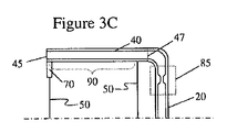
好ましい実施形態では、毛細管通路は、本明細書においてその全内容が引用により組み込まれている本出願人所有の米国特許第6、640、050号に記載されているように、毛細管通路の出口端において制御された温度プロフィールを有するように設計される。そのような実施形態(図3A)では、入口及び出口電極50は、低い電気抵抗値を有し、銅、銀、金、及びアルミニウムなどで作ることができる。毛細管出口45と出口電極50の間に直列に接続した抵抗線70は、毛細管40の10%から30%に等しい電気抵抗値を有する(図3B)。2つの電極50間に十分な電圧が印加されると、毛細管40及び抵抗線70は、電極50に対して温度が上昇する。毛細管40及び抵抗線70の電気抵抗値の適切な比率を用いて、毛細管40の温度が長さに沿って直線的に上昇し、出口45において最大となり、加熱される毛細管の制御された温度プロフィールを提供することになる。
In a preferred embodiment, the capillary passage is the outlet end of the capillary passage as described in commonly owned US Pat. No. 6,640,050, the entire contents of which are incorporated herein by reference. Is designed to have a controlled temperature profile. In such an embodiment (FIG. 3A), the inlet and
空気清浄器設計の別の考慮点は、圧力降下である。毛細管40内の流体が揮発すると圧力が生じる。その圧力は、毛細管40内の流体の一部を液体供給部10に向けて押し戻す可能性があり、全体出力を低下させる。好ましい実施形態では、加熱区画の前の毛細管40の入口端47に狭窄部80を有することが好ましい(図3B)。狭窄部80は、毛細管40の断面積を75%まで(例えば、25〜75%)低減するように形成される。任意的に、狭窄部は、液体供給部10と毛細管40の間に配置された個別のオリフィス85とすることができる(図3C)。
空気清浄器からの出力は、毛細管の数、毛細管内部寸法、及び作動の頻度に依存する。潜在的な実施形態は、共通の液体供給部又は個別の液体供給部(異なる芳香剤を有する)から流体を吸引する平行ないくつかの毛細管を有することができるであろう。制御回路は、各毛細管を連続作動してほぼ連続したエーロゾル出力を生成することができると考えられる。
Another consideration in air cleaner design is pressure drop. When the fluid in the
The output from the air purifier depends on the number of capillaries, the capillary internal dimensions, and the frequency of operation. Potential embodiments could have a number of parallel capillaries that draw fluid from a common liquid supply or separate liquid supplies (with different fragrances). It is believed that the control circuit can continuously operate each capillary to produce a substantially continuous aerosol output.
空気清浄器に対して、粒子サイズができるだけ小さいエーロゾルを生成することが望ましい。ストークスの法則は、空気又は水のような流体中の小球の沈降速度を予測する。ストークスの法則の式は、w=2(ρp−pf)gr2/9μであり、ここで、wは沈降速度、ρは密度(添え字p及びfは、粒子及び流体をそれぞれ表す)、gは重力による加速度、rは粒子の半径、及びμは、流体の動粘性である。以下の表は、1〜50ミクロンの一連の粒子サイズの空気中の沈降速度を示している。 For an air purifier, it is desirable to produce an aerosol with the smallest possible particle size. Stokes' law predicts the settling velocity of small spheres in a fluid such as air or water. The Stokes law equation is w = 2 (ρ p −p f ) gr 2 / 9μ, where w is the settling velocity and ρ is the density (subscripts p and f represent particles and fluid, respectively). , G is the acceleration due to gravity, r is the radius of the particle, and μ is the kinematic viscosity of the fluid. The following table shows the settling velocity in air for a range of particle sizes from 1 to 50 microns.
(表)

生成されるエーロゾル粒子サイズは、好ましくは、5ミクロンよりも小さく、より好ましくは、1〜3ミクロンである。この結果、粒子沈降速度が0.07cm/secよりも小さくなり、エーロゾルを空気中に長期間「漂流させ」、それによって環境内の分布と芳香剤の蒸発を強化する。加圧エーロゾル缶を使用する空気清浄器は、典型的に20ミクロンよりも大きなエーロゾル粒子サイズを有し、従って、エアフレッシュ効果の持続時間(漂流時間)が大幅に短くなることになる。 The aerosol particle size produced is preferably less than 5 microns, more preferably 1-3 microns. This results in a particle settling velocity of less than 0.07 cm / sec, which causes the aerosol to “drift” in the air for extended periods of time, thereby enhancing environmental distribution and fragrance evaporation. Air purifiers using pressurized aerosol cans typically have an aerosol particle size greater than 20 microns, thus significantly reducing the duration of the air fresh effect (drift time).
上述の実施形態の更に別の説明として、かつ図3Cを参照して、電極50の間の毛細管40の領域が毛細管40に沿って加熱部分90(加熱区画)を形成することは認められるものとする。好ましくは、加熱区画は、毛細管40の出口45(先端又は放出端)の近くで終端する。電力サイクルの開始時に、毛細管40に沿ったこの加熱部分90は、液体供給部10から毛細管作用を通じて供給された液体で既に充填されている。そのような毛細管の給送は、芯20又は毛細管40の延長部、又は両方の組合せを通じたものとすることができる。電力サイクル中に、液体が加熱区画90に吸引されるいかなる傾向も加熱区画90内に既にある液体の揮発によって中断され、好ましくは、毛細管40の加熱部分に沿って十分なエネルギが印加され、電力サイクルの終了により加熱区画90に沿って液体が完全に放出される。必要なエネルギは、毛細管40の加熱区画90に沿って収容された液体の容積及び従って質量、及びその質量の潜熱に容積/質量の比熱を加えたものを知り、変動及び損失に適応するように約25%マージンを追加することによって容易に解明される。そのような作動は、毛細管作用を通じた加熱区画90への給送を電力サイクルの完了後に再開することができ、かつ妨げられないように、液体が完全に放出され、かつ毛細管40の加熱区画90に沿ったどの位置にも残らないことを保証する。電力サイクル(液体のエーロゾル化)と電力サイクルの間の時間は、液体供給部10から液体を吸引して加熱区画90を補充する毛細管作用に必要な時間よりも長い時間だけ離間させて時間設定される。
As yet another explanation of the above-described embodiment, and with reference to FIG. 3C, it will be appreciated that the region of the capillary 40 between the
有利な態様では、このシステムは、機械式ポンプ装置の複雑さなしに加熱毛細管エーロゾル発生を達成する。半連続作動は、共通の液体供給部又は個別の液体供給部からのいくつかの毛細管通路を作動させ、反復シーケンスで毛細管通路を次々に作動させるようにコントローラをプログラムすることによって達成することができ、毛細管通路のタイミング及び数は、毛細管液体供給作動が所定の毛細管通路に対する電力サイクルと電力サイクルの間に完了に到達するのに十分なものである。 In an advantageous manner, the system achieves heated capillary aerosol generation without the complexity of a mechanical pump device. Semi-continuous operation can be achieved by activating several capillary passages from a common liquid supply or individual liquid supply and programming the controller to activate the capillary passages one after another in a repeating sequence. The timing and number of capillary passages are sufficient for the capillary liquid supply operation to reach completion between power cycles for a given capillary passage.
開示したシステムは、芳香剤(空気清浄剤など)、防虫剤、殺虫剤、燻蒸剤、潤滑剤、及び害虫及び雑草防除剤などの放出に容易に適応させることができる。屋内の用途を含む静止空気では、本明細書に説明したエーロゾル化システムは、既存の噴霧器に対して開示した噴霧器で達成される小さな粒子サイズのために、エーロゾル粒子の強化された残存時間(漂流時間)、及び少ない液体材料でより多くの噴煙を生成するシステムの機能という理由で特に有利である。
様々な実施形態を説明したが、当業者に明らかなように、変形及び修正に訴えることができることは理解されるものとする。そのような変形及び修正は、本明細書に添付の特許請求の範囲の視野及び範囲であると見なすものとする。
The disclosed system can be readily adapted to release fragrances (such as air fresheners), insect repellents, insecticides, fumigants, lubricants, and pest and weed control agents. In still air, including indoor applications, the aerosolization system described herein is capable of enhanced aerosol particle residence time (drifting) due to the small particle size achieved with the nebulizer disclosed for existing nebulizers. Time) and the ability of the system to produce more plumes with less liquid material, which is particularly advantageous.
While various embodiments have been described, it should be understood that variations and modifications can be appealed to as will be apparent to those skilled in the art. Such variations and modifications are to be considered within the scope and scope of the claims appended hereto.
10 液体供給部
20 芯
40 毛細管
50 電気リード
60 制御回路
DESCRIPTION OF
Claims (28)
入口と出口とを有する毛細管通路と、
毛細管作用のみを通じて前記毛細管通路の前記入口に液体香料物質を供給するように作動可能な液体供給部と、
前記液体香料物質が前記毛細管通路の前記出口から押し出されてエーロゾル化された液体香料物質を形成するように、該毛細管通路に沿って配置された加熱器にわたって電圧を印加し、該毛細管通路における液体香料物質を少なくとも部分的に揮発させるのに十分な温度まで該毛細管通路における液体香料物質を加熱するようになった電源と、
を含むことを特徴とする空気清浄器。 An air purifier for generating an aerosolized liquid perfume material comprising:
A capillary passage having an inlet and an outlet;
A liquid supply operable to supply liquid perfume material to the inlet of the capillary passage only through capillary action;
A voltage is applied across a heater disposed along the capillary passage such that the liquid fragrance material is extruded from the outlet of the capillary passage to form an aerosolized liquid fragrance material, and the liquid in the capillary passage A power supply adapted to heat the liquid perfume material in the capillary passage to a temperature sufficient to at least partially volatilize the perfume material;
An air purifier characterized by comprising.
入口と出口とを有する毛細管通路内に毛細管作用のみを通じて液体香料物質を吸引する段階と、
液体香料物質が、前記毛細管通路の前記出口から押し出されてエーロゾル化された香料物質を形成するように、該毛細管通路に沿って配置された加熱器にわたって電圧を周期的に印加し、該香料物質を少なくとも部分的に揮発させるのに十分な温度まで該毛細管通路における該液体香料物質を加熱する段階と、
を含むことを特徴とする方法。 A method of generating aerosolized perfume material in a pulsed manner,
Aspirating liquid perfume material only through capillary action into a capillary passage having an inlet and an outlet; and
A voltage is periodically applied across a heater disposed along the capillary passage such that liquid fragrance material is extruded from the outlet of the capillary passage to form an aerosolized fragrance material, the fragrance material Heating the liquid perfume material in the capillary passage to a temperature sufficient to at least partially volatilize
A method comprising the steps of:
前記液体香料物質を前記芯から前記毛細管通路の前記入口内に吸引する段階と、
を更に含むことを特徴とする請求項12に記載の方法。 Sucking the liquid perfume material from the liquid supply into the core;
Aspirating the liquid perfume material from the core into the inlet of the capillary passage;
The method of claim 12 further comprising:
a)請求項10に記載の方法に従ってエーロゾル化された香料物質を発生させる段階、
b)毛細管通路を冷却する段階、及び
c)段階a)及びb)を繰り返す段階、
を含むことを特徴とする方法。 A method of repeatedly generating an aerosolized fragrance material in a pulsed manner,
a) generating an aerosolized perfume material according to the method of claim 10;
b) cooling the capillary passage; and c) repeating steps a) and b).
A method comprising the steps of:
毛細管作用を通じて液体を液体供給部から毛細管通路の区画内に吸引することにより、液体を該区画に沿って配置する段階と、
電力サイクル中に毛細管作用を通じた前記液体の吸引が中断され、かつ各電力サイクルの終了時に前記区画に沿って配置された該液体が加熱された区画から排出されるように、該区画に沿って配置された実質的に全ての該液体を揮発させるのに各電力サイクルの熱が十分であるような熱を該区画の少なくとも一部分に沿って該電力サイクルに従って繰返し印加する段階と、
毛細管作用を通じた前記吸引液体が電力サイクルと電力サイクルの間に再開されて前記区画を補充するように十分に時間的に該電力サイクルを離間させる段階と、
を含むことを特徴とする方法。 A method for producing a liquid aerosol comprising:
Placing the liquid along the compartment by aspirating the liquid from the liquid supply through the capillary action into the compartment of the capillary passage;
Along the compartment so that the suction of the liquid through capillary action is interrupted during the power cycle, and the liquid arranged along the compartment is discharged from the heated compartment at the end of each power cycle. Repeatedly applying heat according to the power cycle along at least a portion of the compartment such that heat of each power cycle is sufficient to volatilize substantially all of the disposed liquid;
Separating the power cycle in sufficient time so that the suction liquid through capillary action is resumed between power cycles to replenish the compartment;
A method comprising the steps of:
入口と、出口と、該入口及び出口の間の通路に沿って加熱されるように作動可能な区画とを有する毛細管通路と、
毛細管作用を通じて前記毛細管通路の前記区画内に吸引される液体材料を該毛細管通路の前記入口に供給する液体供給部と、
前記毛細管通路の前記区画の少なくとも一部分に沿って電力サイクルに従って熱を繰返し印加し、該加熱された区画に配置された前記液体材料を揮発させ、そのために該電力サイクル中に毛細管作用を通じた該液体の吸引が中断され、かつ各電力サイクルの終了時に該区画に沿って該配置された液体が該加熱された区画から排出されるように作動可能な電源と、
を含み、
前記電力サイクルは、電力サイクルと電力サイクルの間に毛細管作用を通じた液体の吸引を再開して前記区画を補充するように時間的に十分に離間している、
ことを特徴とするエーロゾル発生器。 An aerosol generator for generating an aerosolized liquid material comprising:
A capillary passage having an inlet, an outlet, and a compartment operable to be heated along the passage between the inlet and the outlet;
A liquid supply for supplying liquid material that is sucked into the compartment of the capillary passage through capillary action to the inlet of the capillary passage;
Heat is repeatedly applied according to a power cycle along at least a portion of the compartment of the capillary passage to volatilize the liquid material disposed in the heated compartment, and thus the liquid through capillary action during the power cycle. A power supply operable to evacuate the liquid and to dispose of the disposed liquid along the compartment from the heated compartment at the end of each power cycle;
Including
The power cycles are sufficiently spaced in time to resume liquid aspiration through capillary action and replenish the compartment between power cycles.
An aerosol generator characterized by that.
Applications Claiming Priority (2)
| Application Number | Priority Date | Filing Date | Title |
|---|---|---|---|
| US93574907P | 2007-08-29 | 2007-08-29 | |
| PCT/IB2008/003020 WO2009027834A2 (en) | 2007-08-29 | 2008-08-29 | Pulsed aerosol generation |
Publications (2)
| Publication Number | Publication Date |
|---|---|
| JP2010537689A true JP2010537689A (en) | 2010-12-09 |
| JP2010537689A5 JP2010537689A5 (en) | 2011-10-13 |
Family
ID=40387942
Family Applications (1)
| Application Number | Title | Priority Date | Filing Date |
|---|---|---|---|
| JP2010522471A Pending JP2010537689A (en) | 2007-08-29 | 2008-08-29 | Pulse aerosol generation method |
Country Status (9)
| Country | Link |
|---|---|
| US (2) | US8442390B2 (en) |
| EP (1) | EP2187977B1 (en) |
| JP (1) | JP2010537689A (en) |
| CN (1) | CN101808673B (en) |
| CA (1) | CA2698547C (en) |
| ES (1) | ES2562668T3 (en) |
| HU (1) | HUE027247T2 (en) |
| PT (1) | PT2187977E (en) |
| WO (1) | WO2009027834A2 (en) |
Families Citing this family (39)
| Publication number | Priority date | Publication date | Assignee | Title |
|---|---|---|---|---|
| US8442390B2 (en) | 2007-08-29 | 2013-05-14 | Philip Morris Usa Inc. | Pulsed aerosol generation |
| KR101761433B1 (en) * | 2009-10-09 | 2017-07-25 | 필립모리스 프로덕츠 에스.에이. | Aerosol generator including multi-component wick |
| AU2010308089B2 (en) * | 2009-10-13 | 2015-05-21 | Philip Morris Products S.A. | Air freshening device |
| US10136672B2 (en) | 2010-05-15 | 2018-11-27 | Rai Strategic Holdings, Inc. | Solderless directly written heating elements |
| US9999250B2 (en) | 2010-05-15 | 2018-06-19 | Rai Strategic Holdings, Inc. | Vaporizer related systems, methods, and apparatus |
| US9095175B2 (en) | 2010-05-15 | 2015-08-04 | R. J. Reynolds Tobacco Company | Data logging personal vaporizing inhaler |
| US10159278B2 (en) | 2010-05-15 | 2018-12-25 | Rai Strategic Holdings, Inc. | Assembly directed airflow |
| US8757147B2 (en) | 2010-05-15 | 2014-06-24 | Minusa Holdings Llc | Personal vaporizing inhaler with internal light source |
| US9259035B2 (en) | 2010-05-15 | 2016-02-16 | R. J. Reynolds Tobacco Company | Solderless personal vaporizing inhaler |
| US9743691B2 (en) | 2010-05-15 | 2017-08-29 | Rai Strategic Holdings, Inc. | Vaporizer configuration, control, and reporting |
| US9861772B2 (en) | 2010-05-15 | 2018-01-09 | Rai Strategic Holdings, Inc. | Personal vaporizing inhaler cartridge |
| WO2013043696A2 (en) | 2011-09-19 | 2013-03-28 | S.C. Johnson & Son, Inc. | Spray dispenser |
| CN202385728U (en) | 2011-11-25 | 2012-08-22 | 周学武 | Electronic cigarette with built-in atomizer |
| US8897629B1 (en) * | 2012-01-27 | 2014-11-25 | Scent Sciences Corporation | Scent delivery apparatus |
| US9108782B2 (en) | 2012-10-15 | 2015-08-18 | S.C. Johnson & Son, Inc. | Dispensing systems with improved sensing capabilities |
| US9408936B2 (en) * | 2014-07-25 | 2016-08-09 | Alfred Esses | Air freshener |
| US20170112194A1 (en) | 2015-10-21 | 2017-04-27 | Rai Strategic Holdings, Inc. | Rechargeable lithium-ion capacitor for an aerosol delivery device |
| US10918134B2 (en) | 2015-10-21 | 2021-02-16 | Rai Strategic Holdings, Inc. | Power supply for an aerosol delivery device |
| JP6652661B2 (en) | 2016-04-27 | 2020-02-26 | コーニンクレッカ フィリップス エヌ ヴェKoninklijke Philips N.V. | Air purifier and environmental fragrance |
| US9861102B2 (en) | 2016-05-26 | 2018-01-09 | Markesbery Blue Pearl LLC | Methods for disinfection |
| US11425911B2 (en) | 2017-05-25 | 2022-08-30 | Markesbery Blue Pearl LLC | Method for disinfection of items and spaces |
| KR20230156173A (en) | 2016-12-01 | 2023-11-13 | 레이 스트라티직 홀딩스, 인크. | Aerosol delivery device and control body |
| US10517326B2 (en) | 2017-01-27 | 2019-12-31 | Rai Strategic Holdings, Inc. | Secondary battery for an aerosol delivery device |
| US10827783B2 (en) | 2017-02-27 | 2020-11-10 | Rai Strategic Holdings, Inc. | Digital compass for an aerosol delivery device |
| US10517330B2 (en) | 2017-05-23 | 2019-12-31 | RAI Stategic Holdings, Inc. | Heart rate monitor for an aerosol delivery device |
| US11337456B2 (en) | 2017-07-17 | 2022-05-24 | Rai Strategic Holdings, Inc. | Video analytics camera system for an aerosol delivery device |
| US10349674B2 (en) | 2017-07-17 | 2019-07-16 | Rai Strategic Holdings, Inc. | No-heat, no-burn smoking article |
| US11039645B2 (en) | 2017-09-19 | 2021-06-22 | Rai Strategic Holdings, Inc. | Differential pressure sensor for an aerosol delivery device |
| US10505383B2 (en) | 2017-09-19 | 2019-12-10 | Rai Strategic Holdings, Inc. | Intelligent charger for an aerosol delivery device |
| US11592793B2 (en) | 2018-11-19 | 2023-02-28 | Rai Strategic Holdings, Inc. | Power control for an aerosol delivery device |
| US11614720B2 (en) | 2018-11-19 | 2023-03-28 | Rai Strategic Holdings, Inc. | Temperature control in an aerosol delivery device |
| US11096419B2 (en) | 2019-01-29 | 2021-08-24 | Rai Strategic Holdings, Inc. | Air pressure sensor for an aerosol delivery device |
| US20200245696A1 (en) | 2019-02-06 | 2020-08-06 | Rai Strategic Holdings, Inc. | Buck-boost regulator circuit for an aerosol delivery device |
| US11676438B2 (en) | 2019-04-02 | 2023-06-13 | Rai Strategic Holdings, Inc. | Authentication and age verification for an aerosol delivery device |
| US11783395B2 (en) | 2019-04-24 | 2023-10-10 | Rai Strategic Holdings, Inc. | Decentralized identity storage for tobacco products |
| US11690405B2 (en) | 2019-04-25 | 2023-07-04 | Rai Strategic Holdings, Inc. | Artificial intelligence in an aerosol delivery device |
| US20200359703A1 (en) | 2019-05-17 | 2020-11-19 | Rai Strategic Holdings, Inc. | Age verification with registered cartridges for an aerosol delivery device |
| WO2021137139A1 (en) | 2019-12-30 | 2021-07-08 | Rai Strategic Holdings, Inc. | A heart rate monitor for an aerosol delivery device |
| US11839239B2 (en) | 2020-08-12 | 2023-12-12 | DES Products Ltd. | Adjustable airflow cartridge for electronic vaporizer |
Citations (5)
| Publication number | Priority date | Publication date | Assignee | Title |
|---|---|---|---|---|
| JPH02149247U (en) * | 1989-05-19 | 1990-12-19 | ||
| JPH04266762A (en) * | 1991-02-22 | 1992-09-22 | Matsushita Electric Ind Co Ltd | Aroma generation device |
| JPH053909A (en) * | 1990-11-30 | 1993-01-14 | Matsushita Electric Ind Co Ltd | Smell producer |
| JPH06315366A (en) * | 1990-11-19 | 1994-11-15 | Philip Morris Prod Inc | Flavor producing article |
| JPH1133097A (en) * | 1997-07-23 | 1999-02-09 | Japan Tobacco Inc | Transpiration device |
Family Cites Families (75)
| Publication number | Priority date | Publication date | Assignee | Title |
|---|---|---|---|---|
| GB1476327A (en) | 1974-03-14 | 1977-06-10 | Boc International Ltd | Electric heaters |
| US4676237A (en) | 1985-01-29 | 1987-06-30 | Boutade Worldwide Investments Nv | Inhaler device |
| US4740366A (en) | 1986-01-21 | 1988-04-26 | Church & Dwight Co., Inc. | Air deodorizer composition and method |
| US5290546A (en) | 1988-02-10 | 1994-03-01 | Earth Chemical Co., Ltd. | Method for thermal vaporization of chemical |
| JPH02209147A (en) | 1989-02-07 | 1990-08-20 | Shimizu Corp | Ultrasonic type scent generator |
| ES2043306T3 (en) | 1989-05-31 | 1993-12-16 | Conceptair Anstalt | PROCEDURE AND ELECTRICAL, ELECTRONIC AND MECHANICAL DEVICE FOR DISTRIBUTING, DOSING OR DIFFUSING, IN LIQUID OR GASEOUS PHASE, FLAVORS, MEDICINAL PRODUCTS AND OTHER LIQUID OR VISCOSE PRODUCTS. |
| IT1231085B (en) | 1989-09-29 | 1991-11-12 | Zobele Ind Chim | APPARATUS TO KEEP VOLATILE INSECTS AWAY FROM PEOPLE, IN PARTICULAR MOSQUITOES AND MANUFACTURING PROCEDURE. |
| US5196171A (en) | 1991-03-11 | 1993-03-23 | In-Vironmental Integrity, Inc. | Electrostatic vapor/aerosol/air ion generator |
| CN2166101Y (en) | 1993-04-20 | 1994-05-25 | 卜冠华 | Gas generator for perfume solvent |
| US5591409A (en) | 1995-08-15 | 1997-01-07 | Watkins; Carl J. | Providing aromas |
| US5647053A (en) | 1995-10-11 | 1997-07-08 | S. C. Johnson & Son, Inc. | Vapor dipensing device |
| BR9601523A (en) | 1996-04-09 | 1998-03-24 | De Sousa Mauricio Araujo | Process and apparatus for programmed aromatization of environments |
| US5743251A (en) | 1996-05-15 | 1998-04-28 | Philip Morris Incorporated | Aerosol and a method and apparatus for generating an aerosol |
| US6325475B1 (en) | 1996-09-06 | 2001-12-04 | Microfab Technologies Inc. | Devices for presenting airborne materials to the nose |
| KR100289448B1 (en) | 1997-07-23 | 2001-05-02 | 미즈노 마사루 | Flavor generator |
| TW384207B (en) | 1997-08-20 | 2000-03-11 | Fumakilla Ltd | Piezoelectric chemical-liquid atomizer apparatus and method for repelling or eliminating harmful organism |
| CN1044314C (en) | 1997-12-01 | 1999-07-28 | 蒲邯名 | Healthy cigarette |
| US6234167B1 (en) | 1998-10-14 | 2001-05-22 | Chrysalis Technologies, Incorporated | Aerosol generator and methods of making and using an aerosol generator |
| US6378780B1 (en) | 1999-02-09 | 2002-04-30 | S. C. Johnson & Son, Inc. | Delivery system for dispensing volatiles |
| AU3510500A (en) | 1999-03-02 | 2000-09-21 | Shaw Mudge & Company | Fragrance and flavor compositions containing odor neutralizing agents |
| MXPA01008926A (en) | 1999-03-05 | 2003-07-21 | Johnson & Son Inc S C | Control system for atomizing liquids with a piezoelectric vibrator. |
| US6293474B1 (en) | 1999-03-08 | 2001-09-25 | S. C. Johnson & Son, Inc. | Delivery system for dispensing volatiles |
| JP2002537961A (en) | 1999-03-12 | 2002-11-12 | マイクロセント, エルエルシー. | Method and apparatus for local delivery of a fragrance aerosol |
| US6361752B1 (en) | 1999-05-19 | 2002-03-26 | S. C. Johnson & Son, Inc. | Apparatus for volatilizing and dispensing a chemical into a room environment |
| US6238646B1 (en) | 1999-05-28 | 2001-05-29 | Global Technology Transfer, L.L.C. | Aqueous aerosol compositions for delivery of atomized oil |
| US6236807B1 (en) | 2000-01-07 | 2001-05-22 | Bath & Body Works, Inc. | Wick-based liquid emanation system with child-resistant and miniaturization features |
| US6792199B2 (en) | 2000-02-25 | 2004-09-14 | The Dial Corporation | Variable temperature vaporizer |
| US6661967B2 (en) | 2000-02-25 | 2003-12-09 | The Dial Corporation | Variable temperature vaporizer |
| US6412494B1 (en) | 2000-03-15 | 2002-07-02 | Walter L. Bloom, Jr. | Aspirating and volatilizing liquid dispenser |
| US6883516B2 (en) | 2000-04-27 | 2005-04-26 | Chrysalis Technologies Incorporated | Method for generating an aerosol with a predetermined and/or substantially monodispersed particle size distribution |
| US6666909B1 (en) | 2000-06-06 | 2003-12-23 | Battelle Memorial Institute | Microsystem capillary separations |
| US6602475B1 (en) | 2000-06-14 | 2003-08-05 | Multisen Technology, Inc. | Multimedia and scent storage medium and playback apparatus having electrostatic scent release |
| US20040265164A1 (en) | 2000-07-27 | 2004-12-30 | The Procter & Gamble Company | Methods, devices, compositions, and systems for improved scent delivery |
| US6386462B1 (en) | 2000-07-31 | 2002-05-14 | S. C. Johnson & Son, Inc. | Method and apparatus for dispensing liquids in aerosolized form with minimum spillage |
| US6501052B2 (en) * | 2000-12-22 | 2002-12-31 | Chrysalis Technologies Incorporated | Aerosol generator having multiple heating zones and methods of use thereof |
| US6701921B2 (en) | 2000-12-22 | 2004-03-09 | Chrysalis Technologies Incorporated | Aerosol generator having heater in multilayered composite and method of use thereof |
| US6491233B2 (en) | 2000-12-22 | 2002-12-10 | Chrysalis Technologies Incorporated | Vapor driven aerosol generator and method of use thereof |
| US6681998B2 (en) | 2000-12-22 | 2004-01-27 | Chrysalis Technologies Incorporated | Aerosol generator having inductive heater and method of use thereof |
| US6799572B2 (en) | 2000-12-22 | 2004-10-05 | Chrysalis Technologies Incorporated | Disposable aerosol generator system and methods for administering the aerosol |
| US7090830B2 (en) | 2001-05-24 | 2006-08-15 | Alexza Pharmaceuticals, Inc. | Drug condensation aerosols and kits |
| JP2005503425A (en) | 2001-05-24 | 2005-02-03 | アレックザ モレキュラー デリヴァリー コーポレイション | Delivery of drug ester by the prescribed inhalation route |
| US7100841B2 (en) | 2001-07-06 | 2006-09-05 | Tri Senx Holdings, Inc. | Fragrance dispenser capillary pump |
| PT2495004E (en) | 2001-07-31 | 2014-07-24 | Philip Morris Products S A S | Method and apparatus for generating a volatilized material |
| US6640050B2 (en) | 2001-09-21 | 2003-10-28 | Chrysalis Technologies Incorporated | Fluid vaporizing device having controlled temperature profile heater/capillary tube |
| US6568390B2 (en) | 2001-09-21 | 2003-05-27 | Chrysalis Technologies Incorporated | Dual capillary fluid vaporizing device |
| US6804458B2 (en) | 2001-12-06 | 2004-10-12 | Chrysalis Technologies Incorporated | Aerosol generator having heater arranged to vaporize fluid in fluid passage between bonded layers of laminate |
| US6681769B2 (en) | 2001-12-06 | 2004-01-27 | Crysalis Technologies Incorporated | Aerosol generator having a multiple path heater arrangement and method of use thereof |
| US6701922B2 (en) | 2001-12-20 | 2004-03-09 | Chrysalis Technologies Incorporated | Mouthpiece entrainment airflow control for aerosol generators |
| US6793149B2 (en) | 2002-02-04 | 2004-09-21 | S. C. Johnson & Son, Inc. | Method and apparatus for evaporating multi-component liquids |
| US6697571B2 (en) | 2002-03-11 | 2004-02-24 | The Dial Corporation | Method and apparatus for selective positioning a wick material in a vapor-dispensing device |
| US6871792B2 (en) | 2002-03-22 | 2005-03-29 | Chrysalis Technologies Incorporated | Apparatus and method for preparing and delivering fuel |
| US6789741B2 (en) | 2002-03-27 | 2004-09-14 | S. C. Johnson & Son, Inc. | Method and apparatus for atomizing liquids having minimal droplet size |
| US6843430B2 (en) | 2002-05-24 | 2005-01-18 | S. C. Johnson & Son, Inc. | Low leakage liquid atomization device |
| US7167641B2 (en) * | 2002-06-06 | 2007-01-23 | S.C. Johnson & Son, Inc. | Localized surface volatilization |
| ATE390840T1 (en) | 2002-06-06 | 2008-04-15 | Johnson & Son Inc S C | DEVICE FOR LOCALIZED SURFACES VOLATIZATION |
| ES2357566T3 (en) | 2002-09-06 | 2011-04-27 | Philip Morris Usa Inc. | AEROSOL GENERATING DEVICES AND METHODS FOR GENERATING AEROSOLS WITH CONTROLLED PARTICLE SIZES. |
| ES2400706T3 (en) | 2002-09-06 | 2013-04-11 | Philip Morris Usa Inc. | Aerosol generation device and method of use |
| US7040314B2 (en) | 2002-09-06 | 2006-05-09 | Philip Morris Usa Inc. | Aerosol generating devices and methods for generating aerosols suitable for forming propellant-free aerosols |
| US6899280B2 (en) | 2002-10-08 | 2005-05-31 | S. C. Johnson & Son, Inc. | Wick-based delivery system with wick having sections of varying porosities |
| US6752327B2 (en) | 2002-10-16 | 2004-06-22 | S. C. Johnson & Son, Inc. | Atomizer with tilted orifice plate and replacement reservoir for same |
| US6772757B2 (en) | 2002-10-25 | 2004-08-10 | Chrysalis Technologies Incorporated | Concentric controlled temperature profile fluid vaporizing device |
| US6786427B2 (en) | 2002-12-19 | 2004-09-07 | S. C. Johnson & Son, Inc. | Liquid sealing arrangements for replaceable liquid reservoirs |
| CN1509820A (en) * | 2002-12-24 | 2004-07-07 | 瑞安大药厂股份有限公司 | Ultrasonic atomizer for generating submicron drops |
| EP1842562A3 (en) | 2003-04-16 | 2007-12-26 | The Procter and Gamble Company | Method and device for improved scent delivery |
| US7683029B2 (en) | 2003-05-07 | 2010-03-23 | Philip Morris Usa Inc. | Liquid aerosol formulations containing insulin and aerosol generating devices and methods for generating aerosolized insulin |
| US7367334B2 (en) | 2003-08-27 | 2008-05-06 | Philip Morris Usa Inc. | Fluid vaporizing device having controlled temperature profile heater/capillary tube |
| CA2564083C (en) | 2004-04-23 | 2014-02-04 | Philip Morris Usa Inc. | Aerosol generators and methods for producing aerosols |
| WO2006086655A1 (en) * | 2005-02-11 | 2006-08-17 | Battelle Memorial Institute | Ehd aerosol dispensing device and spraying method |
| WO2006105154A2 (en) | 2005-03-30 | 2006-10-05 | Greopler Paul J | Method and system for controllably releasing solutions |
| GB2432316A (en) * | 2005-09-15 | 2007-05-23 | Carbonate Ltd | Heated wick assemblies |
| EP2338547B1 (en) * | 2006-02-09 | 2013-04-17 | DEKA Products Limited Partnership | Fluid delivery systems |
| US8442390B2 (en) | 2007-08-29 | 2013-05-14 | Philip Morris Usa Inc. | Pulsed aerosol generation |
| US8201752B2 (en) | 2008-03-10 | 2012-06-19 | Vapore, Inc. | Low energy vaporization of liquids: apparatus and methods |
| EP2100525A1 (en) * | 2008-03-14 | 2009-09-16 | Philip Morris Products S.A. | Electrically heated aerosol generating system and method |
| AU2010308089B2 (en) | 2009-10-13 | 2015-05-21 | Philip Morris Products S.A. | Air freshening device |
-
2008
- 2008-08-28 US US12/230,415 patent/US8442390B2/en active Active
- 2008-08-29 HU HUE08828577A patent/HUE027247T2/en unknown
- 2008-08-29 CN CN200880109695.XA patent/CN101808673B/en active Active
- 2008-08-29 CA CA2698547A patent/CA2698547C/en active Active
- 2008-08-29 EP EP08828577.0A patent/EP2187977B1/en active Active
- 2008-08-29 PT PT88285770T patent/PT2187977E/en unknown
- 2008-08-29 WO PCT/IB2008/003020 patent/WO2009027834A2/en active Application Filing
- 2008-08-29 JP JP2010522471A patent/JP2010537689A/en active Pending
- 2008-08-29 ES ES08828577.0T patent/ES2562668T3/en active Active
-
2013
- 2013-05-10 US US13/891,810 patent/US8897630B2/en active Active
Patent Citations (5)
| Publication number | Priority date | Publication date | Assignee | Title |
|---|---|---|---|---|
| JPH02149247U (en) * | 1989-05-19 | 1990-12-19 | ||
| JPH06315366A (en) * | 1990-11-19 | 1994-11-15 | Philip Morris Prod Inc | Flavor producing article |
| JPH053909A (en) * | 1990-11-30 | 1993-01-14 | Matsushita Electric Ind Co Ltd | Smell producer |
| JPH04266762A (en) * | 1991-02-22 | 1992-09-22 | Matsushita Electric Ind Co Ltd | Aroma generation device |
| JPH1133097A (en) * | 1997-07-23 | 1999-02-09 | Japan Tobacco Inc | Transpiration device |
Also Published As
| Publication number | Publication date |
|---|---|
| US20130243410A1 (en) | 2013-09-19 |
| EP2187977A2 (en) | 2010-05-26 |
| CA2698547A1 (en) | 2009-03-05 |
| US8442390B2 (en) | 2013-05-14 |
| US8897630B2 (en) | 2014-11-25 |
| PT2187977E (en) | 2016-01-20 |
| US20090194607A1 (en) | 2009-08-06 |
| WO2009027834A3 (en) | 2009-07-09 |
| WO2009027834A2 (en) | 2009-03-05 |
| ES2562668T3 (en) | 2016-03-07 |
| HUE027247T2 (en) | 2016-08-29 |
| EP2187977B1 (en) | 2015-12-02 |
| CA2698547C (en) | 2016-06-07 |
| CN101808673B (en) | 2015-09-16 |
| CN101808673A (en) | 2010-08-18 |
Similar Documents
| Publication | Publication Date | Title |
|---|---|---|
| US8897630B2 (en) | Pulsed aerosol generation | |
| EP2488218B1 (en) | Air freshening device | |
| CN108290016B (en) | Aerosol generating system with pump | |
| CN108367128A (en) | The aerosol of translator generates system | |
| EP2770860B2 (en) | An electrically operated aerosol generating system having aerosol production control | |
| CN105142443A (en) | Electronic smoking article | |
| JP2010537689A5 (en) | ||
| JP2005537918A (en) | Aerosol generator and method of using the same | |
| CN109069773A (en) | The vaporization sub-assembly including planar heat-generating body and liquid delivery devices of system is generated for aerosol | |
| JP7267332B2 (en) | Aerosol generating system and method involving dispensing of liquid aerosol-forming substrates by pumped air | |
| KR20200002738U (en) | A Car Odorants Composed with Changable Perfume Cartridge | |
| US20140263695A1 (en) | Method and apparatus for atomizing and vaporizing liquid | |
| CN113197411A (en) | Portable device for atomizing a scented liquid substance |
Legal Events
| Date | Code | Title | Description |
|---|---|---|---|
| A521 | Written amendment |
Free format text: JAPANESE INTERMEDIATE CODE: A523 Effective date: 20110825 |
|
| A621 | Written request for application examination |
Free format text: JAPANESE INTERMEDIATE CODE: A621 Effective date: 20110825 |
|
| A977 | Report on retrieval |
Free format text: JAPANESE INTERMEDIATE CODE: A971007 Effective date: 20120210 |
|
| A131 | Notification of reasons for refusal |
Free format text: JAPANESE INTERMEDIATE CODE: A131 Effective date: 20120216 |
|
| A601 | Written request for extension of time |
Free format text: JAPANESE INTERMEDIATE CODE: A601 Effective date: 20120516 |
|
| A602 | Written permission of extension of time |
Free format text: JAPANESE INTERMEDIATE CODE: A602 Effective date: 20120523 |
|
| A521 | Written amendment |
Free format text: JAPANESE INTERMEDIATE CODE: A523 Effective date: 20120615 |
|
| A131 | Notification of reasons for refusal |
Free format text: JAPANESE INTERMEDIATE CODE: A131 Effective date: 20130307 |
|
| A601 | Written request for extension of time |
Free format text: JAPANESE INTERMEDIATE CODE: A601 Effective date: 20130606 |
|
| A602 | Written permission of extension of time |
Free format text: JAPANESE INTERMEDIATE CODE: A602 Effective date: 20130613 |
|
| A601 | Written request for extension of time |
Free format text: JAPANESE INTERMEDIATE CODE: A601 Effective date: 20130708 |
|
| A602 | Written permission of extension of time |
Free format text: JAPANESE INTERMEDIATE CODE: A602 Effective date: 20130716 |
|
| A601 | Written request for extension of time |
Free format text: JAPANESE INTERMEDIATE CODE: A601 Effective date: 20130807 |
|
| A602 | Written permission of extension of time |
Free format text: JAPANESE INTERMEDIATE CODE: A602 Effective date: 20130814 |
|
| A02 | Decision of refusal |
Free format text: JAPANESE INTERMEDIATE CODE: A02 Effective date: 20140219 |