JP2010536497A - System and method for reducing bubbles in a fluid delivery line - Google Patents
System and method for reducing bubbles in a fluid delivery line Download PDFInfo
- Publication number
- JP2010536497A JP2010536497A JP2010522016A JP2010522016A JP2010536497A JP 2010536497 A JP2010536497 A JP 2010536497A JP 2010522016 A JP2010522016 A JP 2010522016A JP 2010522016 A JP2010522016 A JP 2010522016A JP 2010536497 A JP2010536497 A JP 2010536497A
- Authority
- JP
- Japan
- Prior art keywords
- air
- detection sensor
- predetermined
- threshold
- inline
- Prior art date
- Legal status (The legal status is an assumption and is not a legal conclusion. Google has not performed a legal analysis and makes no representation as to the accuracy of the status listed.)
- Ceased
Links
Images


Classifications
-
- A—HUMAN NECESSITIES
- A61—MEDICAL OR VETERINARY SCIENCE; HYGIENE
- A61M—DEVICES FOR INTRODUCING MEDIA INTO, OR ONTO, THE BODY; DEVICES FOR TRANSDUCING BODY MEDIA OR FOR TAKING MEDIA FROM THE BODY; DEVICES FOR PRODUCING OR ENDING SLEEP OR STUPOR
- A61M5/00—Devices for bringing media into the body in a subcutaneous, intra-vascular or intramuscular way; Accessories therefor, e.g. filling or cleaning devices, arm-rests
- A61M5/14—Infusion devices, e.g. infusing by gravity; Blood infusion; Accessories therefor
- A61M5/168—Means for controlling media flow to the body or for metering media to the body, e.g. drip meters, counters ; Monitoring media flow to the body
- A61M5/16831—Monitoring, detecting, signalling or eliminating infusion flow anomalies
-
- A—HUMAN NECESSITIES
- A61—MEDICAL OR VETERINARY SCIENCE; HYGIENE
- A61M—DEVICES FOR INTRODUCING MEDIA INTO, OR ONTO, THE BODY; DEVICES FOR TRANSDUCING BODY MEDIA OR FOR TAKING MEDIA FROM THE BODY; DEVICES FOR PRODUCING OR ENDING SLEEP OR STUPOR
- A61M5/00—Devices for bringing media into the body in a subcutaneous, intra-vascular or intramuscular way; Accessories therefor, e.g. filling or cleaning devices, arm-rests
- A61M5/36—Devices for bringing media into the body in a subcutaneous, intra-vascular or intramuscular way; Accessories therefor, e.g. filling or cleaning devices, arm-rests with means for eliminating or preventing injection or infusion of air into body
- A61M5/365—Air detectors
Abstract
流体送達ラインパルスにおいて空気を正確に感知し、あるいは流体送達サイクルの圧送段階中、空気センサ(複数可)を複数回作動および作動停止させ、ライン内の空気の単一指示または累積指示に基づいて警告を生成することができる方法およびポンプ。ポンプは、送達ラインに沿って離間された複式空気センサを含むことができ、それによって、方法は、複式空気センサからの複数の信号を使用して、実際に動いている気泡を誤検出および/またはラインの内壁に付着された気泡から区別することができるようになる。 Accurately sense air in fluid delivery line pulses, or activate and deactivate air sensor (s) multiple times during the pumping phase of the fluid delivery cycle, based on a single or cumulative indication of air in the line A method and pump that can generate warnings. The pump can include dual air sensors spaced along the delivery line, so that the method uses multiple signals from the dual air sensor to falsely detect and / or detect bubbles that are actually moving. Alternatively, it becomes possible to distinguish from bubbles attached to the inner wall of the line.
Description
本発明は、流体などの物質を患者に送達するための医療用ポンプに関する。特に、本発明は、流体送達ライン内の気泡の形成を低減および/または防止する、医療用ポンプと共に使用される、ラインセット内などの流体送達ラインにおける空気の検出に関する。 The present invention relates to a medical pump for delivering a substance, such as a fluid, to a patient. In particular, the present invention relates to the detection of air in a fluid delivery line, such as in a line set, used with a medical pump that reduces and / or prevents the formation of bubbles in the fluid delivery line.
現在の医療的ケアは、医療用ポンプ装置を使用して流体および/または薬液などの物質を患者に送達することを伴うことが多い。医療用ポンプは、患者への物質の制御された送達を可能にし、そのようなポンプは、主に送達流量および投薬量における精度がはるかに高く、柔軟でありながらも制御された送達スケジュールが可能になることにより、重力流システムにとって代わることが多くなってきた。 Current medical care often involves using a medical pump device to deliver substances such as fluids and / or medicinal solutions to a patient. Medical pumps allow controlled delivery of substances to patients, such pumps are much more accurate, primarily in delivery flow rates and dosages, and allow flexible yet controlled delivery schedules Has become an alternative to gravity flow systems.
一般的な容積式ポンプシステムは、ポンプ装置ドライバと、それだけには限定されないが、カセット、注射筒またはチュービング部分を含むさまざまな形態で画定された使い捨て可能な流体または圧送チャンバとを含む。1人の患者および1回の流体送達のみに使用されるようになされた使い捨て可能なカセットは、通常、流体供給容器および流体を受け入れる患者に可撓性のチュービングを介してそれぞれ接続された入口および出口を有する小型のプラスチックユニットである。カセットは、圧送チャンバを含み、チャンバを通る流体の流れは、装置ドライバによって制御された方法で作動されるプランジャまたは圧送要素によって制御されている。 A typical positive displacement pump system includes a pump device driver and a disposable fluid or pumping chamber defined in various forms including, but not limited to, a cassette, syringe barrel or tubing portion. Disposable cassettes intended to be used for only one patient and one fluid delivery typically have an inlet connected to the fluid supply container and the patient receiving the fluid, respectively, via flexible tubing and A small plastic unit with an outlet. The cassette includes a pumping chamber, and fluid flow through the chamber is controlled by a plunger or pumping element that is actuated in a manner controlled by the device driver.
たとえば、カセットチャンバは、流体を流すためにプランジャおよびドライバによって往復運動される可撓性の弾性ダイアフラムまたは薄膜によって形成された1つの壁または壁部分を有することができる。ポンプドライバ装置は、カセット内の圧送チャンバに入るおよびそこから出る流体の流れを制御するためのプランジャまたは圧送要素を含み、またこの装置は、流体が、事前設定された流量、所定の方法、および特定の事前選択された時間または総投薬量でのみ患者に送達されることを保証するための制御機構も含む。 For example, the cassette chamber can have a single wall or wall portion formed by a flexible elastic diaphragm or membrane that is reciprocated by a plunger and driver to flow fluid. The pump driver device includes a plunger or pumping element for controlling the flow of fluid into and out of the pumping chamber in the cassette, and the device is configured to allow the fluid to flow through a preset flow rate, a predetermined method, and A control mechanism is also included to ensure that it is delivered to the patient only at a specific preselected time or total dosage.
流体は、入口を通ってカセットに入り、圧力下で出口を通じて押し出される。流体は、ポンププランジャが薄膜を圧送チャンバ内に押し入れて流体を変位させるときに出口に送達される。吸気行程中、ポンププランジャは引っ込み、圧送チャンバを覆う薄膜はその前の完全に変位した形状から引き戻り、このとき流体は、開いた入口を通って圧送チャンバ内に引き込まれる。圧送行程では、ポンププランジャは、圧送チャンバ内に含有された流体を加圧し、出口を通じて押し出すために、薄膜を圧送チャンバ内に押し戻す。したがって、流体は、連続的な流れではなく間隔をあけた一連のパルスでカセットから流れる。 Fluid enters the cassette through the inlet and is forced through the outlet under pressure. The fluid is delivered to the outlet when the pump plunger pushes the membrane into the pumping chamber to displace the fluid. During the intake stroke, the pump plunger retracts and the membrane covering the pumping chamber is pulled back from its previous fully displaced shape, where fluid is drawn into the pumping chamber through the open inlet. In the pumping stroke, the pump plunger pushes the membrane back into the pumping chamber to pressurize the fluid contained in the pumping chamber and push it out through the outlet. Thus, fluid flows from the cassette in a series of spaced pulses rather than a continuous flow.
当技術分野でよく知られているポリマーチューブなどの流体送達ラインは、流体送達ラインに接続されたカテーテルまたは針などを介して流体を流体貯留器から患者に送達するために、医療用ポンプ装置と共に使用される。1つの従来の医療用ポンプでは、医療用ポンプは、流体送達ライン内で空気および/または気泡を感知するための、トランスミッタおよびレシーバを有する空気感知装置を含んでいた。トランスミッタは、ポンプ内の、流体送達ラインが医療提供者によって医療用ポンプ装置内に取り付けまたは組み込まれたときに流体送達ラインの第1の側に隣接する場所に配置される。レシーバは、ポンプ内の、流体送達ラインが医療提供者によって医療用ポンプ装置内に取り付けまたは組み込まれたときに流体送達ラインの第1の側とは反対の第2の側に隣接する場所に配置される。トランスミッタは、流体送達ライン内を移動する超音波信号を送信し、この超音波信号は、流体送達ラインのトランスミッタとは反対側にあるレシーバによって受信される。トランスミッタによって送信され、レシーバによって受信された信号は、トランスミッタとレシーバの間で信号が遭遇する物理的要素(流体送達ライン、流体送達ライン内の空気、流体送達ライ内の流体など)によって変更され、あるいは影響が及ぼされる。 A fluid delivery line, such as a polymer tube, well known in the art, along with a medical pump device to deliver fluid from a fluid reservoir to a patient, such as via a catheter or needle connected to the fluid delivery line. used. In one conventional medical pump, the medical pump included an air sensing device having a transmitter and receiver for sensing air and / or bubbles in the fluid delivery line. The transmitter is disposed in the pump at a location adjacent to the first side of the fluid delivery line when the fluid delivery line is installed or incorporated into the medical pump device by the healthcare provider. The receiver is located in the pump at a location adjacent to the second side opposite the first side of the fluid delivery line when the fluid delivery line is installed or incorporated into the medical pump device by the healthcare provider. Is done. The transmitter transmits an ultrasound signal that travels within the fluid delivery line, which is received by a receiver on the opposite side of the fluid delivery line from the transmitter. The signal transmitted by the transmitter and received by the receiver is modified by the physical elements that the signal encounters between the transmitter and receiver (fluid delivery line, air in the fluid delivery line, fluid in the fluid delivery line, etc.) Or it is affected.
参照によって本明細書に組み込まれる、Coleらの米国特許第6,142,008号で開示された1つの医療用ポンプシステムでは、モータが圧送カセットを作動させる間、コントローラは、流体送達ラインの一部分にわたって気泡センサによってサンプリングを制御する。コントローラは、気泡センサからのサンプリングされた信号と、流体送達ライン内の液体の存在を示すように見出された最後の読取値の固定の割合である所定の閾値とを比較することにより、各サンプルが100%空気であるか、100%液体であるかを判断する。サンプリングされた信号が、有効であり、所定の閾値を下回る場合、コントローラは、このサンプルが空気の存在を示すことを判断する。反対に、有効なサンプリングされた信号が所定の閾値を上回る場合、コントローラは、このサンプルが遠位のチュービング内の液体の存在を示すことを判断する。コントローラは、総液体量および総空気量を判断するために使用されるデルタ値として各サンプルに関連付けられた量を蓄積する。 In one medical pump system disclosed in US Pat. No. 6,142,008 to Cole et al., Which is incorporated herein by reference, the controller is a part of the fluid delivery line while the motor operates the pumping cassette. The sampling is controlled by the bubble sensor. The controller compares each sampled signal from the bubble sensor to a predetermined threshold that is a fixed percentage of the last reading found to indicate the presence of liquid in the fluid delivery line. Determine whether the sample is 100% air or 100% liquid. If the sampled signal is valid and falls below a predetermined threshold, the controller determines that this sample indicates the presence of air. Conversely, if the valid sampled signal is above a predetermined threshold, the controller determines that this sample indicates the presence of liquid in the distal tubing. The controller accumulates the amount associated with each sample as a delta value used to determine the total liquid volume and total air volume.
この医療用ポンプシステムでは、各サンプルは、遠位のチュービングの現在のサンプリングより前のサンプリングされていない部分の代表近似となり、空気のサンプリング時間間隔は、サンプリングされていない時間間隔を近似する。コントローラは、モータの出力駆動軸の比率を用いて、モータの連続回転のためのサンプリングの時間間隔(秒単位)を判断しなければならない。たとえば、圧送カセットが高い流量(たとえば1000ml/時)で圧送し、サンプリングの時間間隔が40ミリ秒未満である場合、コントローラは、サンプリング時間間隔をたとえば40ミリ秒に設定しなければならない。さらに、圧送カセットが低い流量(たとえば126ml/時未満)で圧送している場合、サンプリングの時間間隔は、比率および他の要因に基づいて32ミリ秒で設定しなければならない。理想的には、サンプリングの時間間隔は、圧送カセット内の弁が開くときに開始し、この時間間隔は、弁が閉じるときに終了する。 In this medical pump system, each sample represents a representative approximation of the unsampled portion prior to the current sampling of the distal tubing, and the air sampling time interval approximates the unsampled time interval. The controller must determine the sampling time interval (in seconds) for continuous rotation of the motor using the ratio of the motor output drive shaft. For example, if the pumping cassette is pumping at a high flow rate (eg, 1000 ml / hour) and the sampling time interval is less than 40 milliseconds, the controller must set the sampling time interval to, eg, 40 milliseconds. Furthermore, if the pumping cassette is pumping at a low flow rate (eg, less than 126 ml / hr), the sampling time interval must be set at 32 milliseconds based on the ratio and other factors. Ideally, the sampling time interval begins when the valve in the pumping cassette opens, and this time interval ends when the valve closes.
この医療用ポンプシステムでは、コントローラは、モータが圧送カセットを作動させていないときは気泡センサの電源を切る。言い換えれば、コントローラは、圧送カセットの各作動間では気泡センサへの電源を停止するが、作動中は気泡センサの電源を入れたままにする。コントローラが作動開始直前に気泡センサの電源を入れるとき、センサが使用され得るまでに約1ミリ秒の起動時間が必要とされる。コントローラは、気泡センサからの出力信号について、関連する増幅電子機器の電源が最初に入れられたとき、および気泡センサのトランスミッタが超音波パルスを気泡センサのレシーバに送信していないときに誤った高さでないかを確認する。 In this medical pump system, the controller turns off the bubble sensor when the motor is not operating the pumping cassette. In other words, the controller stops power to the bubble sensor between each actuation of the pumping cassette, but keeps the bubble sensor powered on during operation. When the air bubble sensor is turned on just before the controller begins to operate, a startup time of about 1 millisecond is required before the sensor can be used. The controller detects that the output signal from the bubble sensor is high when the associated amplification electronics are first turned on and when the bubble sensor transmitter is not sending an ultrasonic pulse to the bubble sensor receiver. Check if it is not.
流量および他の可変値に依存する、気泡センサのサンプリングレートを判断するなどの気泡センサの制御を含む、本特許で説明されるようなさまざまな機能のために、コントローラによって方程式が使用される。加えて、流体送達ライン内で空気を検出し、流体送達ライン内で十分な空気が検出されたときに警告を与えるために、さまざまな論理フローが使用される。しかしこれらの方程式および論理フローは、各行程の引き込みではない部分全体、すなわち加圧段階中は気泡センサの電源を入れた状態に保つという動作理論に基づいている。 Equations are used by the controller for various functions as described in this patent, including control of the bubble sensor, such as determining the sampling rate of the bubble sensor, which depends on the flow rate and other variable values. In addition, various logic flows are used to detect air within the fluid delivery line and provide an alert when sufficient air is detected within the fluid delivery line. However, these equations and logic flow are based on the theory of operation of keeping the bubble sensor powered on during the entire portion that is not a pull-in of each stroke, ie the pressurization phase.
本発明の主な目的は、これらの欠点を克服するために、医療用ポンプおよび医療用ポンプの作動方法を提供することである。本発明は、上記で説明された問題および他の問題を解決し、従来の医療用ポンプによって提供されない利点および態様を提供するために提供される。 The main object of the present invention is to provide a medical pump and a method of operating the medical pump to overcome these drawbacks. The present invention is provided to solve the problems described above and other problems and to provide advantages and aspects not provided by conventional medical pumps.
したがって、本発明の1つの目的は、不快な警告を低減することを含む。 Accordingly, one object of the present invention includes reducing unpleasant warnings.
1つのさらなる目的は、ポンプ作動中の空気検出センサの使用回数を低減すると同時に流体送達ラインにおける信頼高い空気検出を提供することにより、流体送達ラインを通り抜ける超音波から生じる可能性がある躍動する泡を低減することを含む。 One further object is the buoyant foam that can result from ultrasound passing through the fluid delivery line by reducing the number of times the air sensing sensor is used during pump operation while providing reliable air detection in the fluid delivery line. Reducing.
1つの追加の目的は、ポンプ作動の送達段階中の空気検出センサの使用回数を低減すると同時に流体送達ラインにおける信頼高い空気検出を提供することにより、流体送達ラインを通り抜ける超音波から生じる可能性がある躍動する泡を低減することを含む。 One additional objective may arise from ultrasound passing through the fluid delivery line by reducing the number of uses of the air detection sensor during the pumped delivery phase while providing reliable air detection in the fluid delivery line. Including reducing certain buoyant bubbles.
1つのさらなる目的は、ポンプ作動中の空気検出センサの使用回数を低減すると同時に流体送達ラインにおける信頼高い空気検出を提供することにより、流体送達ラインを通り抜ける超音波から生じる可能性がある泡の生成および/または小さな泡の蓄積/集塊を低減することを含む。 One further objective is the generation of bubbles that may result from ultrasound passing through the fluid delivery line by reducing the number of times the air detection sensor is used during pump operation while providing reliable air detection in the fluid delivery line. And / or reducing the accumulation / agglomeration of small bubbles.
1つの追加の目的は、ポンプ作動の送達段階中の空気検出センサの使用回数を低減すると同時に流体送達ラインにおける信頼高い空気検出を提供することにより、流体送達ラインを通り抜ける超音波から生じる可能性がある泡の生成および/または小さな泡の蓄積/集塊を低減することを含む。 One additional objective may arise from ultrasound passing through the fluid delivery line by reducing the number of uses of the air detection sensor during the pumped delivery phase while providing reliable air detection in the fluid delivery line. Including reducing the generation of certain bubbles and / or the accumulation / agglomeration of small bubbles.
1つのさらなる目的は、実際の送達時間における経験的試験および/または送達条件(すなわちチューブタイプ、使用流体、温度など)による少なくとも所定の、適応的および/または動的閾値選択を用いて、空気検出の方法およびシステムにおいて堅牢性を確立することを含む。 One further objective is to detect air using at least predetermined, adaptive and / or dynamic threshold selection by empirical testing and / or delivery conditions (ie tube type, working fluid, temperature, etc.) at the actual delivery time. Establishing robustness in the method and system.
1つの追加の目的は、1つまたは複数の圧送機構に対する第1およびその次の空気検出センサの「波動音(ping)(複数可)」ベースの時間および/または回転角度(稼働時間(hard times)および/または角度、および/または基準点からの遅延)の知的および/または適応的配置(いつ/どこ)を含む。 One additional purpose is the “ping (s)” based time and / or rotation angle (hard times) of the first and subsequent air detection sensors for one or more pumping mechanisms. ) And / or angle, and / or delay from reference point) and / or adaptive placement (when / where).
1つのさらなる目的は、既存のポンプハードウェア技術を使用し、そのソフトウェアコードを本発明のシステムおよび方法を実施するように更新することを含む。 One further objective includes using existing pump hardware technology and updating its software code to implement the system and method of the present invention.
1つの追加の目的は、たとえば複式空気検出センサを使用して流体送達ライン内で気泡を検出することにより、躍動する泡から生じる不快な警告を低減することを含む。 One additional objective includes reducing unpleasant warnings resulting from buoyant bubbles, for example, by detecting bubbles in the fluid delivery line using a dual air detection sensor.
本発明の特徴および利点の十分な説明は、以下の概要、詳細な説明および添付の図に委ねられる。 A full description of the features and advantages of the present invention is deferred to the following summary, detailed description, and accompanying drawings.
本発明は、第1のトランスミッタおよび第1のレシーバを備えた第1の空気検出センサを有する医療用ポンプを使用して、流体送達ライン内で空気を検出するための改善された方法を伴った医療用ポンプを対象とする。1つの実施形態では、医療用ポンプはまた、第2のトランスミッタおよび第2のレシーバを備えた第2の空気検出センサも有する。第1および第2の両方のセンサは、流体送達ライン内に空気が存在するか、および流体送達ライン内のその空気の量を感知するために提供される。本明細書でより詳細に説明されるように、医療用ポンプの1つの実施形態は、流体などの物質を患者に送達するためのカセットまたはチューブなどの使い捨て可能な圧送チャンバに接続して提供される。医療用ポンプは、さらに、物質に圧力を加えるために圧送チャンバ上に力を及ぼすためのポンプドライブを含む。医療用ポンプはまた、ポンプドライブの位置を連続的に感知するためにポンプドライブに動作可能に接続されたポンプドライブ位置センサも含む。医療用ポンプは、さらに、ポンプドライブ、ポンプドライブ位置センサおよび第1の空気検出センサと電子通信する、これらの要素の制御を提供し、また、さまざまな判断を行い、本明細書で提供される医療用ポンプを作動させる際に利用する入力情報を受け入れるためのプロセッサまたは処理ユニットを有する。医療用ポンプは、さらに、プロセッサと電子通信するメモリを有する。メモリは、プロセッサによる実行のためのプログラミングコードをその中に記憶させることができる。プログラミングコードは、少なくとも部分的には、本発明の方法を全体的に実施する。 The present invention involves an improved method for detecting air in a fluid delivery line using a medical pump having a first air detection sensor with a first transmitter and a first receiver. Intended for medical pumps. In one embodiment, the medical pump also has a second air detection sensor with a second transmitter and a second receiver. Both first and second sensors are provided to sense the presence of air in the fluid delivery line and the amount of that air in the fluid delivery line. As described in more detail herein, one embodiment of a medical pump is provided in connection with a disposable pumping chamber such as a cassette or tube for delivering a substance, such as a fluid, to a patient. The The medical pump further includes a pump drive for exerting a force on the pumping chamber to apply pressure to the substance. The medical pump also includes a pump drive position sensor operably connected to the pump drive for continuously sensing the position of the pump drive. The medical pump further provides control of these elements in electronic communication with the pump drive, pump drive position sensor and first air detection sensor, and also makes various decisions and is provided herein. A processor or processing unit for receiving input information for use in operating the medical pump; The medical pump further has a memory in electronic communication with the processor. The memory can have programming code stored therein for execution by the processor. The programming code at least partially implements the method of the present invention entirely.
1つの実施形態では、方法および医療用ポンプは、流体送達サイクルを開始することを含む。流体送達サイクルが開始すると、医療用ポンプは、第1の所定のサイクルパラメータ値が満たされた後、第1の空気検出センサを作動させる、あるいはこれに電源供給する。このおよび他の所定のサイクルパラメータ値は、行程サイクルが開始した後に経過した時間でよく、ポンプドライブが移動した角度距離でよく、圧送チャンバが動いた線形距離でよく、かつ/または何らかの他の時間、距離、またはストークサイクルの開始または何らかの他の基準点からセンサの作動の間隔をあける他のパラメータでよい。1つの実施形態では、各流体送達サイクルまたは行程は、以下により詳細に説明されるように、加圧段階、圧送段階、および引き込み段階を含む。次いで、医療用ポンプは、第1の空気検出センサによって生成された第1の空気量(air content)信号を測定する。第2のまたは複数の空気検出センサが使用されるとき、医療用ポンプはまた、第2のまたは複数の追加の空気検出センサによって生成された第2のまたは複数の追加の空気量信号も測定することになるが、第2のまたは複数の追加の空気検出センサに関する測定、検出および/または判断は、時間または距離の遅延などの所定のまたは算出された(動的)な遅延後に実施され得る。医療用ポンプは、次いで、アナログ信号を、空気検出センサによって測定された信号を表すデジタル値またはデータに変換するなどにより、第1の(第2/複数の追加の)空気量信号(複数可)から第1の(および追加の空気検出センサが存在するときは、第2/複数の追加の)空気量データを生成する。プロセッサは、空気量信号ごとに複数のサンプルを受け入れ、そのサンプルの各々をアナログ信号からデジタル値に変換することができる。本明細書では、信号という用語は、単数でも複数でもよく、「信号」または「信号(複数)」が言及されるとき、たとえば異なる時間における同じ信号など、単一の信号または複数の信号から複数のサンプルが取られ得ることを当業者は理解されたい。プロセッサは、測定された第1の空気信号に対するサンプルの各々を平均化するように構成され得る。次いで、プロセッサは、空気量信号を測定した後、および移動距離または時間などの第2の(第2などの空気検出センサに関しては第3など)の所定のサイクルパラメータ値が満たされた後、第1の(第2/複数の追加の)空気検出センサを作動停止させる。 In one embodiment, the method and medical pump include initiating a fluid delivery cycle. When the fluid delivery cycle begins, the medical pump activates or powers the first air detection sensor after the first predetermined cycle parameter value is met. This and other predetermined cycle parameter values may be the time that has elapsed since the start of the stroke cycle, the angular distance that the pump drive has moved, the linear distance that the pumping chamber has moved, and / or some other time. , Distance, or other parameters that spaced the actuation of the sensor from the start of the stalk cycle or some other reference point. In one embodiment, each fluid delivery cycle or stroke includes a pressurization phase, a pumping phase, and a retraction phase, as will be described in more detail below. The medical pump then measures a first air content signal generated by the first air detection sensor. When the second or multiple air detection sensors are used, the medical pump also measures a second or multiple additional air quantity signals generated by the second or multiple additional air detection sensors. It will be appreciated that the measurement, detection and / or determination for the second or more additional air detection sensors may be performed after a predetermined or calculated (dynamic) delay, such as a time or distance delay. The medical pump then converts the analog signal to a digital value or data that represents the signal measured by the air detection sensor, etc., such as the first (second / multiple additional) air quantity signal (s). To generate first (and second / multiple additional air quantity data if additional air detection sensors are present). The processor can accept multiple samples for each air quantity signal and convert each of the samples from an analog signal to a digital value. As used herein, the term signal may be singular or plural, and when “signal” or “signal (s)” is referred to, for example, a single signal or a plurality of signals, such as the same signal at different times. One skilled in the art will appreciate that multiple samples can be taken. The processor may be configured to average each of the samples for the measured first air signal. The processor then measures the air quantity signal and after a second predetermined cycle parameter value such as travel distance or time (such as third for an air detection sensor such as second) is satisfied, Deactivate one (second / multiple additional) air detection sensors.
医療用ポンプは、さらに、空気量データ(または空気検出データ)が第1の所定の空気閾値を満たしているかを判断する。プロセッサは、第1の空気量信号を測定する前に空気インラインカウンタをゼロに設定する。1つの実施形態では、第1の所定の閾値が満たされていることは、流体送達ライン内に空気が存在することを表している。第1の所定の閾値が満たされる場合、1つの実施形態では、プロセッサは、空気インラインカウンタを増分する。1つの実施形態では、増分のサイズは、圧送サイクルの1ストークの1/3の行程量(stroke volume)でよい。プロセッサは、さらに、空気インラインカウンタが警告閾値を満たしているかを判断し、警告閾値が満たされている場合は空気のインライン警告を発する。警告閾値は、製造者によって工場で設定されてよく、かつ/または医療提供者または生物医学設計者によって変更されてよく、かつ/または特定の臨床ケア領域、ポンプタイプ、ポンプのソフトウェアバージョン、患者のタイプ(たとえば成人対幼児)または薬物に合わせてユーザによってカスタマイズされ得るダウンロード可能な薬物ライブラリパラメータとして構成されてよい。別の実施形態では、第1の所定の閾値が満たされない場合、空気インラインカウンタはゼロに設定される。 The medical pump further determines whether the air amount data (or air detection data) satisfies a first predetermined air threshold value. The processor sets the air in-line counter to zero before measuring the first air quantity signal. In one embodiment, meeting the first predetermined threshold indicates the presence of air in the fluid delivery line. If the first predetermined threshold is met, in one embodiment, the processor increments the air inline counter. In one embodiment, the size of the increment may be a stroke volume of 1/3 of one stoke of the pumping cycle. The processor further determines whether the air inline counter meets a warning threshold and issues an air inline warning if the warning threshold is met. The warning threshold may be set at the factory by the manufacturer and / or may be changed by the health care provider or biomedical designer and / or the specific clinical care area, pump type, pump software version, patient's It may be configured as a downloadable drug library parameter that can be customized by the user for type (eg adult vs. infant) or drug. In another embodiment, the air inline counter is set to zero if the first predetermined threshold is not met.
同じ行程内において、プロセッサは、上記で提供され、以下でより詳細に説明されるように、距離または時間などの第3の(第4のなど)所定のサイクルパラメータ値が満たされた後、第1の(第2/複数の追加の)空気検出センサ(複数可)を再作動させる。次いで、医療用ポンプは、第1の(第2/複数の追加の)空気検出センサ(複数可)によって生成された第2の空気量信号を測定し、第1の空気量信号(複数可)と類似の方法で、(空気検出センサごとに)第2の空気量信号(複数可)から第2の空気量データを生成する。プロセッサは、さらに、第2の空気量データ(または空気検出データ)が第1の所定の空気閾値を満たしているかを判断し、第2の空気量信号を測定した後、および距離または時間などの第4の所定のサイクルパラメータ値が満たされた後、第1の空気検出センサを作動停止させる。 Within the same stroke, the processor is provided with the third predetermined cycle parameter value, such as distance or time, as described above in more detail below, after the third cycle parameter value is met. Reactivate one (second / multiple additional) air detection sensor (s). The medical pump then measures the second air amount signal generated by the first (second / additional) air detection sensor (s) and the first air amount signal (s). To generate second air quantity data from the second air quantity signal (s) (for each air detection sensor). The processor further determines whether the second air amount data (or air detection data) meets a first predetermined air threshold, measures the second air amount signal, and such as distance or time After the fourth predetermined cycle parameter value is satisfied, the first air detection sensor is deactivated.
1つの実施形態では、第1および他の所定のサイクルパラメータ値は、サイクルまたは行程の開始以降の時間など、あるいはサイクルまたは行程の開始以降にポンプドライブが進んだ距離など、流体送達サイクルの開始に関連するものでよい。第2および他の所定のサイクルパラメータ値もまた、第1およびその次の所定のサイクルパラメータ値に関連するもの、またはいつ(時間)またはどこ(場所)でそのような値が満たされたかに関連するものでもよい。 In one embodiment, the first and other predetermined cycle parameter values are at the start of the fluid delivery cycle, such as the time since the start of the cycle or stroke, or the distance traveled by the pump drive since the start of the cycle or stroke. It can be related. The second and other predetermined cycle parameter values are also related to the first and subsequent predetermined cycle parameter values, or when (time) or where (location) such values are met. You may do it.
さらなる実施形態では、プロセッサは、医療提供者によって設定された送達流量に基づく速度でポンプドライブを回転または駆動させるようにこのポンプドライブを制御することができる。送達流量およびポンプドライブ速度は、行程速度を確立する。医療用ポンプによって測定され受け入れられるサンプルの数は、この行程速度とは無関係である。したがって、空気量信号の取り出されたサンプルの数を含む、測定が行われる方法は、送達ライン内を動く流体の速度に依存しない。 In a further embodiment, the processor can control the pump drive to rotate or drive the pump drive at a rate based on the delivery flow rate set by the healthcare provider. Delivery flow rate and pump drive speed establish the stroke speed. The number of samples measured and accepted by the medical pump is independent of this stroke rate. Thus, the method by which the measurements are made, including the number of samples taken of the air quantity signal, is independent of the velocity of the fluid moving in the delivery line.
追加の実施形態では、プロセッサは、第1の所定の閾値が満たされたとき、空気インラインカウンタを増分する。第1の所定の閾値が満たされない場合、プロセッサは、空気インラインカウンタをゼロに設定することになる。第1の所定の閾値が満たされているかのこの判断は、プログラミングされたループ内で継続する。この判断が行われるたびに、プロセッサは、第1の空気量信号を測定するステップが行われるたびに直近にある、空気インラインカウンタの「現在」値を表している別の空気インラインカウンタ値を記憶する。したがって、複数の記憶される空気インラインカウンタ値が作り出され、記憶される。プロセッサは、さらに、複数の記憶された空気インラインカウンタ値の各々が第1の所定の空気インラインカウンタの閾値を満たしているかを判断する。第1の所定の空気インラインカウンタの閾値を満たしていない複数の記憶された空気インラインカウンタ値の各々に対しては、プロセッサは、そのような複数の記憶された空気インラインカウンタ値の各々をゼロに設定するように構成される。 In an additional embodiment, the processor increments the air inline counter when the first predetermined threshold is met. If the first predetermined threshold is not met, the processor will set the air inline counter to zero. This determination of whether the first predetermined threshold is met continues in the programmed loop. Each time this determination is made, the processor stores another air inline counter value representing the "current" value of the air inline counter that is closest each time the step of measuring the first air quantity signal is made. To do. Thus, a plurality of stored air in-line counter values are created and stored. The processor further determines whether each of the plurality of stored air inline counter values meets a first predetermined air inline counter threshold. For each of a plurality of stored air inline counter values that do not meet a first predetermined air inline counter threshold, the processor zeros each of the plurality of such stored air inline counter values. Configured to set.
プロセッサおよびプログラミングコードはまた、現在の累積空気インラインカウンタ値を確立するようにも構成され得る。1つの実施形態では、現在の累積空気インラインカウンタ値は、連続的な非ゼロの記憶された空気インラインカウンタ値の群ごとに最も高い記憶された空気インラインエアカウンタ値を判断し、その最も高い記憶された空気インラインカウンタ値を以前に判断された累積空気インラインエアカウンタ値に追加することによって確立される。次いで、プロセッサは、現在の累積空気インラインカウンタ値が累積空気インラインカウンタ値の閾値を満たしているかを判断する。もし満たしていれば、プロセッサは、累積空気インライン警告を発する。この判断は、所定の累積時間の間隔にわたって実施され得る。流体送達サイクルが開始するとき、所定の累積時間間隔は、流体送達サイクルの開始時に開始する。時間が経過すると、所定の累積時間間隔は移り、このとき最も古い値は、新しい「現在」値が「ムービングウィンドウ(moving window)」または先入れ先出し(FIFO)プロセスで判断され記憶されるときに消え落ちる。 The processor and programming code may also be configured to establish a current cumulative air inline counter value. In one embodiment, the current cumulative air inline counter value determines the highest stored air inline air counter value for each group of consecutive non-zero stored air inline counter values, and the highest stored Established air inline counter value is added to the previously determined cumulative air inline air counter value. The processor then determines whether the current cumulative air inline counter value meets a threshold for the cumulative air inline counter value. If so, the processor issues a cumulative air inline warning. This determination may be performed over a predetermined cumulative time interval. When the fluid delivery cycle begins, the predetermined cumulative time interval begins at the beginning of the fluid delivery cycle. As time elapses, the predetermined cumulative time interval shifts, where the oldest value disappears when the new “current” value is determined and stored in a “moving window” or first-in first-out (FIFO) process. .
上記で提供されたように、医療用ポンプは、流体送達ライン内で空気を検出するために、流体送達ラインに沿って第1の空気検出センサの下流側または上流側に追加の空気検出センサを有することができる。第1の所定のサイクルパラメータ値が満たされた後で第2の(または複数の追加の)空気検出センサ(複数可)が使用されるとき、医療用ポンプは、第2の(複数の追加の)空気検出センサ(複数可)によって生成された第1の空気量信号を測定する。プロセッサおよびその中で実行するプログラミングコードは、第2の(複数の追加の)空気検出センサ(複数可)によって生成された第1の空気量信号から第1の空気量データを生成するように構成される。2つの空気センサが使用されるとき、プロセッサは、さらに、第1の空気検出センサによって生成された第1の空気量信号が、第1の空気検出時間を確立するためにいつ測定されるかを判断するように構成される。プロセッサはまた、第2の空気検出センサによって生成された第1の空気量信号が、第2の空気検出時間を確立するためにいつ測定されるかを判断し、第2の検出時間と第1の検出時間の間の相違が所定の遅延時間を満たしているかを判断するようにも構成される。所定の遅延時間は、以下でより詳細に説明されるように、流体送達ラインのサイズ、送達流量、および/または第1の空気検出センサと第2の空気検出センサの間の距離に依存し得る。これらの原理およびステップはまた、3つ以上の空気検出センサが存在する実施形態にも適用されることを当業者は理解されたい。1つの実施形態では、プロセッサは、第2の検出時間と第1の検出時間の間の相違が所定の遅延時間を満たしていない場合に空気インラインカウンタをゼロに設定するように構成される。 As provided above, the medical pump has an additional air detection sensor downstream or upstream of the first air detection sensor along the fluid delivery line to detect air within the fluid delivery line. Can have. When the second (or more) additional air detection sensor (s) is used after the first predetermined cycle parameter value is met, the medical pump ) Measure a first air quantity signal generated by the air detection sensor (s). The processor and programming code executing therein are configured to generate first air quantity data from the first air quantity signal generated by the second (multiple additional) air detection sensor (s). Is done. When two air sensors are used, the processor further determines when the first air quantity signal generated by the first air detection sensor is measured to establish a first air detection time. Configured to judge. The processor also determines when the first air volume signal generated by the second air detection sensor is measured to establish the second air detection time, and the second detection time and the first It is also configured to determine whether the difference between the detection times satisfies a predetermined delay time. The predetermined delay time may depend on the size of the fluid delivery line, the delivery flow rate, and / or the distance between the first air detection sensor and the second air detection sensor, as described in more detail below. . Those skilled in the art will appreciate that these principles and steps also apply to embodiments where there are more than two air detection sensors. In one embodiment, the processor is configured to set the air inline counter to zero if the difference between the second detection time and the first detection time does not meet a predetermined delay time.
2つのセンサの実施形態を続けると、第2の検出時間と第1の検出時間の間の相違が所定の遅延時間を満たしている場合、プロセッサは、第2の検出データ間の相違が所定の複式センサ許容値を満たしている/満たしていないかを判断する。所定の複式センサ許容値が満たされないとき、プロセッサは、前の1つの実施形態に類似して、たとえば1/3の行程量だけ空気インラインカウンタを増分するように構成される。また、前の1つの実施形態と同様に、プロセッサは、空気インラインカウンタが警告閾値を満たしているかを判断し、警告閾値が満たされているときは空気インライン警告を発する。 Continuing with the two sensor embodiment, if the difference between the second detection time and the first detection time meets a predetermined delay time, the processor determines that the difference between the second detection data is a predetermined value. It is determined whether or not the dual sensor allowable value is satisfied. When the predetermined dual sensor tolerance is not met, the processor is configured to increment the air in-line counter by, for example, 1/3 stroke amount, similar to the previous embodiment. Also, as in the previous embodiment, the processor determines whether the air inline counter meets the warning threshold and issues an air inline warning if the warning threshold is met.
別の実施形態では、プロセッサは、さらに、第2の空気検出センサによって生成された第1の量信号を測定した後、および第2の所定のサイクルパラメータ値が満たされた後、第2の空気検出センサを作動停止させるように構成される。第3の所定のサイクルパラメータ値が満たされた後、医療用ポンプ/プロセッサはまた、第2の空気検出センサを再作動させ、第2の空気検出センサによって生成された第2の空気量信号を測定し、第2の空気検出センサによって生成された第2の空気量信号から第2の空気量データを生成するようにも構成される。第2の空気検出センサによって生成された第2の空気量信号を測定した後、および第4の所定のサイクルパラメータ値が満たされた後、プロセッサは、第2の空気検出センサを作動停止させるように構成される。第3および第4の所定のサイクルパラメータの値は、第2の空気量信号が送達サイクルの圧送段階の終了前に測定されるようにする。ここでもやはり、これらの原理およびステップはまた、3つ以上の空気検出センサを含む実施形態にも適用されることを当業者は理解されたい。 In another embodiment, the processor further measures the second air after measuring the first quantity signal generated by the second air detection sensor and after the second predetermined cycle parameter value is met. It is configured to deactivate the detection sensor. After the third predetermined cycle parameter value is met, the medical pump / processor also reactivates the second air detection sensor and generates a second air quantity signal generated by the second air detection sensor. It is also configured to measure and generate second air quantity data from the second air quantity signal generated by the second air detection sensor. After measuring the second air quantity signal generated by the second air detection sensor and after the fourth predetermined cycle parameter value is met, the processor is configured to deactivate the second air detection sensor. Configured. The values of the third and fourth predetermined cycle parameters cause the second air quantity signal to be measured before the end of the pumping phase of the delivery cycle. Again, those skilled in the art will appreciate that these principles and steps also apply to embodiments that include more than two air detection sensors.
本発明の他の特徴および利点は、以下の図を併用して以下の明細書から明白になるであろう。 Other features and advantages of the present invention will become apparent from the following specification, taken in conjunction with the following drawings.
本発明を理解するために、次に、添付の図を参照して例示により本発明が説明される。 For an understanding of the invention, the invention will now be described by way of example with reference to the accompanying drawings.
本発明は、多くの異なる形態の実施形態が可能であるが、本開示が、本発明の原理の例示として考慮されるべきであり、本発明を図示された実施形態に限定することが意図されないという理解の下で、本発明の詳細な好ましい実施形態が図に示され、本明細書において説明される。 While the invention is susceptible to many different forms of embodiment, the disclosure is to be considered as illustrative of the principles of the invention and is not intended to limit the invention to the illustrated embodiments. With the understanding, detailed preferred embodiments of the present invention are shown in the figures and described herein.
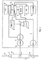
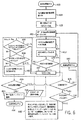
医療用ポンプは、それだけには限定されないが、腸内ポンプ、注入ポンプ、カセットポンプ、注射器ポンプ、蠕動ポンプ、または患者への静脈内投与または動脈内投与による流体の送達のための任意の容積式流体圧送装置を含む。最初に図1を参照すれば、医療用ポンプ10の1つの実施形態が、流体などの物質を患者に送達するためのカセット12またはチューブなどの使い捨て可能な圧送チャンバと接続して提供されている。本発明の医療用ポンプのさまざまな実施形態では、圧送チャンバは、医療用ポンプのタイプに応じて、カセット、チューブ、および/または注射器の少なくとも1つの一部分である。医療用ポンプ10は、ポンプの性能を評価するために使用される公称データからの変動に基づいて物質の実際の送達を調整するための機構を提供する。ポンプ10内には処理ユニット30が含まれ、以下により詳細に説明されるさまざまな作動を実行する。入力/出力装置32は、処理ユニット30と通信し、ユーザが処理ユニット30からの出力を受信し、かつ/または情報または命令を処理ユニット30に入力することを可能にする。入力/出力装置32は、別個のディスプレイ装置および/または別個の入力装置として設けられてよいことを当業者は理解するであろう。メモリ34は、処理ユニット30と通信し、処理ユニット30がポンプ10の作動状態を算出および出力するのに必要なコードおよびデータを記憶する。メモリ34は、医療用ポンプ10の作動状態を判断し、制御するようにデータを処理するために本発明によって形成されたプログラミングコード36を記憶する。ポンプ内10で時間を記録するために、時計37が使用される。時計37は、処理ユニット30に接続され、データを経時的に相互に関連付ける、または時間依存の動作を実施するための時間情報を処理ユニット30に与える。電子モータ38は、処理ユニット30によって制御され、モータ38に接続されたシャフト42を回転式に駆動させるための原動機としての機能を果たすために電源装置40によって通電される。処理ユニット30は、使用されているモータに応じて、またポンプ10を通る所望の流量に応じて、一定の速度または異なる速度で作動するようにモータ38に対して命令する。下降行程、すなわち行程の送達部分は、モータ38を電源装置40から直接作動させている。上昇行程、すなわち行程の引き込みまたは充填部分は、引き込み時間が処理ユニット30によって変更されるように処理ユニット30によって設定された電圧で作動され、この場合、より高流量を望むときはより高速の引き込みが必要になる。プランジャなどの圧送要素44が、シャフト42に動作可能に関連付けられる。通電されると、圧送要素44は、前後に往復作動して周期的に下降行程を行って、圧送要素44が圧送チャンバ24を押し付け、そこから流体を放出させるようにする。上昇行程時、圧送要素44は、圧送チャンバ24から圧力を逃がし、それによって流体を入口ポート14から圧送チャンバ24内に引き入れる。こうして、圧送要素44は、圧送サイクル中、圧送チャンバ24を断続的に加圧する。電源装置40、モータ38、および/または圧送要素44は、一緒に、単独で、または何らかの組み合わせにおいて、本明細書の目的のためのポンプドライブであると考慮されてよい。
Medical pumps include but are not limited to enteral pumps, infusion pumps, cassette pumps, syringe pumps, peristaltic pumps, or any positive displacement fluid for delivery of fluids by intravenous or intraarterial administration to a patient Includes a pumping device. Referring initially to FIG. 1, one embodiment of a
ポンプドライブのステップ値は、ポンプドライブを駆動する時間、ポンプドライブを駆動する線形距離、ポンプドライブが移動する角度距離または角度、および/または何らかの他の移動値でよい。モータは、一定速度または可変速度で駆動されてよい。一定速度のモータまたはモータドライブを使用する医療用ポンプ10の1つの形態では、そのようなモータドライブは、一続きのカムを介して、プランジャなどの圧送要素44の可変速度の動きを生じさせる。しかし、上記で述べられたように、可変速度のモータまたはモータドライブは、一定速度のプランジャなどの一定速度の圧送要素の動きを生じさせるために使用されてよい。算出、判断、および送達スキームは、当業者が理解するように適宜変化する。当業者が理解するように、他の部品および/または要素もまたポンプドライブを構成することができる。加えて、電源装置40、モータ38、圧送要素44、および/または他の要素の各々の部分は、圧送チャンバの使用による患者への物質の送達を駆動するためにポンプドライブが処理ユニット30によって制御されるという理解の下で、本明細書ではポンプドライブと称されるものを構成することができる。
The step value of the pump drive may be the time to drive the pump drive, the linear distance to drive the pump drive, the angular distance or angle that the pump drive moves, and / or some other movement value. The motor may be driven at a constant speed or a variable speed. In one form of
力/圧力センサ46は、圧送チャンバ24上に圧送要素44によって及ぼされた力または圧力を検出するために圧送要素44に動作可能に関連付けられる。図1に示されるように、センサ46は、圧送要素に直接接続され、圧送要素44と直列に、圧送チャンバ24とモータ38のシャフト42の間に配置され得る。この実施形態では、センサ46は、医療用ポンプ10内に含まれた唯一の力/圧力センサであり、圧送要素44上の力/圧力を感知するだけでなく、この力/圧力に基づいて力/圧力信号を生成するように作動する。力/圧力センサ46は、処理ユニット30と電子通信して、ポンプ10の作動状態を判断するのに使用するための力/圧力信号を処理ユニット30に送信する。圧力センサ46は、力変換器、歪みゲージ、または圧送要素44によって圧送チャンバ24を圧迫するためにもたらされた圧力または関連する力を動作可能に感知することができる任意の他の装置でよいことを当業者は理解するであろう。
A force /
圧送要素44の位置を直接的にまたは間接的に検出するために、位置センサ48が圧送要素44に動作可能に関連付けられる。位置センサ48は、各圧送サイクル内の各位置において圧送要素44の位置を検出することによってポンプ10の各圧送サイクルを追跡する。図示されるように、位置センサ48は、シャフト42に関連付けられている。位置センサ48は、シャフト42の回転位置を検出することによってポンプドライブの移動信号を生成する。位置センサ48は、処理ユニット30と電子通信して位置信号を処理ユニット30に送信する。処理ユニット30は、この情報を、参照によって本明細書に組み込まれる、System And Method For Improved Low Flow Medical Pump Deliveryという表題の2006年8月25日出願の米国特許出願第11/510,106号に説明されたものなどのさまざまな方法で利用することができる。1つの方法は、入来する力/圧力データを圧送サイクル内の特定の移動値、たとえば時間、線形距離、および/または回転距離または移動角度などに関連付けることを含む。位置センサ48が、シャフト42または圧送要素44に取り付けられたカムを代わりに追跡できることを当業者は理解するであろう。さらに、本明細書で使用される位置センサ48は、それだけに限定されないが、テコ式(pivoting)ダイヤルインジケータなどの機械式インジケータ、電子スイッチ、ホール効果センサ、および光ベースの位置検出器を含むことを当業者は理解するであろう。
A
好ましい実施形態では、モータ38は、モータ1回転当たり512カウントの全分解能に対して、4分割(in quadrature)で使用される128カウント磁気抵抗エンコーダを備えたブラシDCモータである。ポンプサイクルを実行するのに必要なモータシャフト42の回転数に応じて、サイクルは非常に細かな位置数に分割され得る。たとえば、1回の圧送サイクルまたは行程(1つの実施形態では360°)を完了するのにポンプシャフト42が10回転する場合、各サイクルは、5120の移動位置または値に分離され得る。したがって、この例では、位置センサ48は、処理ユニット30が他の算出および判断において判断するおよび/または利用するために、1サイクル当たり5120の移動位置の分解能を可能にする情報を提供することができる。
In the preferred embodiment, the
1つまたは複数の空気センサまたは空気検出センサ60が、出口流体ライン22内などの流体ライン内で空気を検出するために処理ユニット30に動作可能に関連付けられる。処理ユニット30は、信号および/またはデータを空気検出センサ(複数可)60から受信する。医療用ポンプ10の1つの実施形態では、空気検出センサ(複数可)60は、出口流体ライン22のチュービングの外面に押し付けられ、これと物理的に接触する。電源装置は、空気検出センサ(複数可)60(接続線は図示されず)に電源供給することができ、この空気検出センサ(複数可)60は、アナログ信号を生成し、これをプロセッサに与えるために超音波で出口流体ライン22を励起するように構成される。空気検出センサ(複数可)60からのアナログ信号は、デジタルデータに変換されて、以下でより詳細に説明されるように、出口流体ライン22内に含有された空気の正確な空気量データを提供する。正常な作動においては、一般に、この空気量データは予想される範囲内にあり、処理ユニット30(および当業者に理解されるように、その中で)は、適正な流体の流れが進行中であることを判断する。空気量が予想される範囲外であるとき、一般に、処理ユニット30は、不適正な空気量が患者に送達されていることを判断して示している。本明細書でより詳細に説明されるように、処理ユニット30は、出口流体ライン22内などの流体送達ライン内に不適正な空気が存在するかをより正確に検出するために、空気検出センサ(複数可)60を制御し、さまざまな判断を行うことができる。
One or more air sensors or
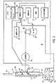
図2は、図1に示されるものに類似する実施形態を示している。しかし、特有のカセット12は、その内部構築が図示された状態で示されている。加えて、2連式空気検出センサ装置80が図示されている。
FIG. 2 shows an embodiment similar to that shown in FIG. However, the
具体的には、図1に示されるように、カセット12は、主要本体18内に形成された入口14および出口16を含むことができる。入口流体ライン20は、主要本体18上の入口ポート14をIVバッグまたは他の流体容器などの流体源に接続させる。同様に、出口流体ライン22は、主要本体18上の出口ポート16を患者の体に接続させる。図2に示されるように、主要本体18内には、入口弁26および出口弁28が配置される。圧送チャンバ24は、入口ポート14と出口ポート16の間で流体連通するように接続される。圧送チャンバ24は、カセット12を通る流体を計量するように作動する。入口弁26は、入口ポート14と圧送チャンバ24の間に位置する。入口弁26は、入口ポート14と圧送チャンバ24の間の流体連通を物理的に開閉するように作動する。出口弁28は、圧送チャンバ24と出口ポート16の間に位置する。出口弁28は、圧送チャンバ24と出口ポート16の間の流体連通を物理的に開閉するように作動する。圧送チャンバ24、入口弁26、および出口弁28はすべて、カセット12を通る流体の流れを制御するためにポンプ10に動作可能に関連付けられる。カセットは、流体送達前に圧送チャンバ24の加圧を要求する受動弁システムである。入口弁26および出口弁28は、圧送チャンバ24にかかる圧送要素44の圧力に反応する。作動においては、流体などの物質は、入口14を通って入り、圧力下で出口16を通じて押し出される。流体は、ポンプ10が流体を排出させるように圧送チャンバ24を圧縮するときに出口16に送達される。このカセットの追加の詳細および他の詳細ならびに情報は、2005年9月29日公開の、US2005/0214129A1で見出され得、その全体は、参照によって本明細書に組み込まれ、本明細書の一部として構成される。
Specifically, as shown in FIG. 1, the
図2の実施形態では、力/圧力センサ46は、カセット12の圧送チャンバ24内に少なくとも部分的に配置された圧力プローブを備える。圧力プローブからの電流信号は、圧送要素44によって圧送チャンバ24上に及ぼされた力に比例する。図1のケースと同様に、力/圧力センサ46は、医療用ポンプ10内に含まれた唯一の力/圧力センサであり、圧送要素44上の力/圧力を感知するだけでなく、この力/圧力に基づいて処理ユニット30への力/圧力信号を生成するように作動する。本発明が力/圧力センサのタイプおよび場所に関係なく適用可能であることを当業者は理解するであろう。
In the embodiment of FIG. 2, the force /
本発明の医療用ポンプ10は、ポンプの性能を推定するために使用される公称データからの変動に基づいて流体の実際の送達を制御または調整するための機構を提供する。処理ユニット30は、メモリ34から作動状態のプログラミングコード36を検索し、これをポンプサイクル中に受信された力/圧力および移動データに適用する。力/圧力データおよび移動データは、処理ユニット30によって処理される。たとえば圧送チャンバ24が圧送要素44に対抗する力を及ぼす力/圧力を感知し、力/圧力データが医療用ポンプを作動させるのに使用されるさまざまなパラメータを判断することができることを分析する。処理ユニット30は、これらのパラメータを閉ループサイクル/行程フィードバックシステム内で利用して、送達パラメータを判断および/または算出する。医療用ポンプ10のこのおよび他の実施形態についての追加の情報は、参照によって本明細書に組み込まれる、System And Method For Improved Low Flow Medical Pump Deliveryという表題の2006年8月25日出願の米国特許出願第11/510,106号において見出され得る。
The
加えて、図2に示されるように、複式空気検出センサ組立体80が提供される。1つの実施形態では、複式空気検出センサ組立体80は、2連式空気検出センサ組立体である。2連式空気検出センサ組立体80は、第1の空気検出センサ90と、第2の空気検出センサ100とを含む。第1の空気検出センサ90は、第1のトランスミッタ82と、第1のレシーバ84とを含む。第2の空気検出センサ100は、第2のトランスミッタ86と、第2のレシーバ88とを含む。第1および第2のトランスミッタ82、86は、医療用ポンプ10内の、流体送達ライン22が医療提供者によって医療用ポンプ10内に取り付けまたは組み込まれたときに流体送達ライン22の第1の側に隣接する場所に配置される。第1および第2のレシーバ84、88は、流体送達ライン22が医療提供者によって医療用ポンプ10内に取り付けまたは組み込まれたときに流体送達ライン22の第1の側とは反対の第2の側に隣接する場所に配置される。
In addition, as shown in FIG. 2, a dual air
第1および第2のトランスミッタ、82、86はそれぞれ、流体送達ライン22内を移動し、流体送達ライン22の第1および第2のトランスミッタ84、88とは反対側のそれぞれの第1および第2のレシーバ84、88によって受信される超音波信号を送信する。第1および第2のトランスミッタ82、86によって送信され、それぞれの第1および第2のレシーバ84、88によって受信された各信号は、信号が第1および第2のトランスミッタ82、86とレシーバ84、88のそれぞれの対の間で遭遇する物理的要素(流体送達ライン、流体送達ライン内の空気、流体送達ライン内の流体など)によって変更され、あるいは影響が及ぼされる。第1および第2の空気検出センサ90、100の制御ならびにこれらのセンサによって生成された信号の使用については、図4〜図6ならびに他の図を参照して以下でより詳細に説明される。
The first and
図1および図2を続いて参照すれば、処理ユニット30と共にメモリ34は、プロセスユニット30が医療用ポンプ10の作動状態を算出し、出力するために必要なプログラムコード36およびデータを記憶する。処理ユニット30は、メモリ30からプログラムコード36を検索し、これを医療用ポンプ10のさまざまなセンサおよび装置から受信されたデータに適用する。具体的には、処理ユニット30は、医療用ポンプ10からのデータを処理して、患者へのカセット12を通る流体の適正な流れが存在するとき、また、流体送達ライン内にカセット12を離れる流体内に同伴する気泡などの気泡が存在する場合を含む、さまざまな作動状態を判断する。作動状態が判断されると、処理ユニット30は、その作動状態をディスプレイ32に出力し、インジケータまたは警告を作動させ、かつ/または判断された作動状態を使用して医療用ポンプ10の作動を調整することができる。
With continued reference to FIGS. 1 and 2, the
カセット12が完全に正しく着座し、圧送作動が開始した後、患者へのカセット12を通る流体の適正な流れを判断するために、圧力データの配列が処理ユニット30によって分析される。1つの使用においては、処理ユニット30は、圧力センサ46からのこの圧力信号を使用して、カセットが圧送要素44を適正に押し付けていることを判断し、カセット12の圧送を開始するように圧送要素44を作動させる。同様に、処理ユニット30は、方位センサ(図示されず)から受信されたデータを処理することによってカセット12の方向および存在を判断する。カセット12が間違って方向付けられる場合(たとえば、後ろ向きまたは逆さま)、全くカセットが存在しない場合、あるいはカセット12が完全に着座していない場合、処理ユニット30は、不適正な適正なカセット装着が行われたことを判断する。
After
さらに、処理ユニット30が、方位センサから受信されたデータを処理して開いたキャリッジ内の適正に装着されたカセットの存在を判断すると、処理ユニット30は、所与の期間後、直接的なユーザの命令無しでキャリッジ組立体を自動的に閉じるようにプログラミングされ得る。これは、手動で実行されてもよい。処理ユニット30は、ディスプレイ/入力装置32と通信し、ユーザが処理ユニット30からの出力を受信し、かつ/または(データまたは命令を)処理ユニット30に入力することを可能にする。カセット12が開いたキャリッジ組立体内に装着されるとき、ユーザは、ディスプレイ/入力装置32にアクセスしてキャリッジ組立体を自動的に閉じるよう医療用ポンプ10に命令する。同様に、カセット12が取り外される、および/または交換されるときには、ユーザは、ディスプレイ/入力装置32にアクセスしてキャリッジ組立体を自動的に開くよう医療用ポンプ10に命令する。
Further, when the
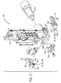
図3を参照すれば、分解された組立体の図は、空気検出センサ組立体の1つの実施形態を含む、1つのキャリッジ組立体300の機能的構成要素を示している。具体的には、1対の空気検出センサキャリア302は、空気センサアーム306の端部近くに取り付けられたセンサヘッド304を含む。図3のキャリッジ組立体300の1つの実施形態では、空気検出センサヘッド304の1つは、第1のトランスミッタ82であり、空気検出センサヘッド304の1つは、第1のレシーバ84であり、これらは共に図1に関連して上記で説明されたように空気センサ60を画定している。図3のキャリッジ組立体300の別の実施形態では、空気検出センサヘッド304の1つが、第1のトランスミッタ82と、出口流体ライン22の長さに沿って(ここでは軸方向にまたは垂直に)第1のトランスミッタ82から離間して置かれた第2のトランスミッタ86とを含み/組み込み、空気検出センサヘッド304の1つが、第1のレシーバ84と、出口流体ライン22の長さに沿って第1のレシーバ84から同様に離間して置かれた第2のレシーバ88とを含み/組み込んで、図2に示され、上記で言及された複式空気検出センサ装置80を画定している。アーム306は、各々がピン部材312と、ピン部材312を枢動的に受け入れるためのソケット314とを備えるヒンジにおいてベース面310に枢動的に固定される。アーム306はそれぞれ、その中に形成された、空気センサカム320上に配置されたカムポスト318を受け入れるカム細溝316を有する。空気センサのアクチュエータ324は、空気センサアーム306を開閉するようにセンサカム320に関連付けられる。ガイド要素328は、アーム306および空気センサカム320の両方の動きを誘導するためにベース面310から延びている。図3は、複式センサ装置80を組み込むための単一の対の空気検出キャリア302を示しているが、当業者は、複数の離間された空気検出センサキャリア302がアーム306上に設けられ得ることを理解することができる。あるいは、各々が単一空気検出センサのキャリア302を備えた複数のアーム306が、複式センサ装置を組み込むために使用されてよい。
Referring to FIG. 3, the exploded assembly diagram shows the functional components of one
キャリッジ組立体300が開位置に移動しているとき、処理ユニット30(図示されず)は、空気センサカム320を内側に押し出すように空気センサアクチュエータ324を(図示されないが、電源装置40を介して)作動させ、それによってアーム306はヒンジ周りで枢動し、センサヘッド304は離れるように動く。キャリッジ組立体300が閉位置に移動しているとき、処理ユニット30(図示されず)は、空気センサカム320を外方向に移動させるように空気センサアクチュエータ326を作動させ、それによってアーム306はヒンジ周りで枢動し、センサヘッド304は一緒に動く。カム細溝316のプロファイルは、急速移動ゾーンを含むように設計され得、この急速移動ゾーンでは、カム細溝316は、トランスミッタ/レシーバの対82/84(および適宜86/88)が流体送達ライン22(図示されず)に接触するまでアーム306が急速に近づくようになっている。カム細溝316はまた、カム細溝316のプロファイルが、アーム306が除々に圧縮されるようになっている圧縮ゾーン、ならびに各々のカム細溝316のプロファイルが、真直ぐであり、アーム306が、空気センサカム320のさらなる動きを伴ってもそれ以上は近づかない「停止」ゾーンを含むこともできる。本発明の空気感知態様は、それだけに限定されないが、注射器ポンプ、往復プランジャポンプおよび蠕動ポンプを含む、他のタイプの医療用ポンプに適用可能であることが理解されるであろう。たとえば、キャリッジ装着器は、注射器またはチュービングの部分を自動的に装着することができ、キャリア302上の空気検出センサ60、90、100は、注射器、注射器に接続されたチュービング、またはチュービングの注射器に関連付けられないチュービング部分内に存在する空気を感知することができる。
When the
図4〜図6を参照して、次に、空気検出センサ60、90および100の作動が、処理ユニット30およびその中で実行するプログラミングコード34と関連付けて、流体送達ライン内で空気を検出することに関して説明される。以下の説明は、カセット12がキャリッジ組立体300内にすでに挿入され取り付けられていることを想定する。流体送達ライン内で空気の検出を実施するために、1つの実施形態では、処理ユニット30はプログラミングコード36を実行する。図4および図5を参照すれば、プログラミングコード36の1つの実施形態の全体的な実行が、(図1および図2に示される)1つまたは第1の空気検出センサ60、90を有する空気検出組立体80に関して示されている。たとえば図6に示される「2連式空気センサ」の実施形態などの、後で説明される複式空気検出センサの実施形態を容易に理解するために、第2の空気検出センサ100に適用可能な場合、その時々で第2の空気検出センサ100、およびそのそれぞれの構成要素に参照がなされる。
4-6, the operation of the
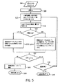
図4は、単一空気インライン検出のフロー図である。具体的には、ブロック400は、サイクル開始位置にあるモータ38および/または圧送要素44などのポンプドライブを含む方法の開始を表している。残りのブロックのほとんどは、プログラミングコード36における中断または枝分かれが作用を起こすまで、処理ユニット30がプログラミングコード36を介してループするたびに実行するプログラミングコード36の作動を表している。簡単に提示するために、多くの中間段階のステップおよびプログラミングループは示されておらず、その多くは、いずれも当業者に知られている、かつ/または参照によって別の明細書から本明細書に組み込まれている。
FIG. 4 is a flow diagram for single air in-line detection. Specifically, block 400 represents the start of a method that includes a pump drive such as
続いて、ブロック404は、流体が流体送達ライン22に導入される前に、第1の所定の空気閾値を、医療用ポンプ10の設定時間または何らかの時間で設定する作動を表している。具体的には、処理ユニット30は、第1の空気検出センサ90の第1のレシーバ84からアナログ信号を受信し、このとき処理ユニット30は流体送達ライン22内に流体が存在しないことを知る。このアナログ値は、図4〜図6において「ADC」(アナログデジタル変換値)によって表されたデジタル値に変換される。別に、1つの実施形態では、各々のADC値は、8つのサンプルをとり、それらのサンプルを平均化してADC値を得るなど、アナログ値の読み取りにおける誤差を低減するために時間内で最も近い複数のサンプルの平均である。さらに、電圧であるアナログ値は、正確性を高め処理を容易にするために、0から4095のデジタル範囲内でデジタル値に変換される。この範囲は、流体送達ライン22内の空気と流体の間の相違を判断するために設けられる。1つの実施形態では、本明細書で説明されるように、処理ユニット30による使用のために、12ビットのデジタルデータが空気検出センサ90、100によって提供される。
Subsequently, block 404 represents the act of setting the first predetermined air threshold at the set time or some time of the
ブロック404に続くと、第1の所定の閾値を得るために、150などのオフセット値が、「誤った空気」の表示を低減するために、流体送達ライン22内に流体が存在しない間に測定されたADC値から差し引かれる。処理ユニット30は、ベンチマークを使用して次のようにこの較正を開始し、実行することができる:空気センサ内に(トランスミッタ(複数可)82、86とレシーバ(複数可)84、88の間に)十分に呼び水が入れられたマクロボアチューブが依然として存在し得る場合であっても、空気検出センサ90、100は、トランスミッタ(複数可)82、86の電源が切られた状態(乾燥測定)でADCdry>3350を返す。次いで、処理ユニット30は、トランスミッタ(複数可)82、86の電源が入れられた状態(湿潤測定「ADCwet」で同じ判断を実行する。空気検出センサ(複数可)は、ADCwet<ADCdry−400に適合すべき値を返す。400のこの好ましいオフセットは、経験的に判断された。具体的には、ADC値(検出基準に基づいて主に流体を構成するものまたは主に空気を構成するもの)の選択は、さまざまな温度におけるさまざまな流体、チューブのタイプに対する何百もの試験データの平均化に基づいている。単一の閾値の使用は、1つの技術解決策が、動的に確立された閾値の実施に余分な費用をかけることなく、さまざまなシナリオにわたってうまく機能することができる(すなわちこれが90%以上の信頼度でうまく機能する)ように行われる。そのように使用する際、システムの堅牢性は、わずかに低減されることがあり、より大きな誤差範囲が存在することがある。これに対処するための1つの方法は、チュービングの各タイプ、温度および/または使用される薬剤(流体)に対して一意的な(可変の)閾値を動的に選択または決定することである。この判断を行うためにプロセッサによって必要とされる情報は、薬用バイアル、送達セット(バッグおよびチュービングセット)上のバーコード内に提供され得る。薬物(流体)/チュービング/温度のライブラリは、ポンプ内に記憶され、かつ/または中央サーバに記憶されおよび/またはそこからダウンロードされ得る。ライブラリは、各チューブタイプ、流体タイプ、および/または温度に対する閾値の適切なセットを有して構築され得る。この判断はまた、空気センサアームを作動させるのに使用されるモータのチューブに接近するのに必要とされる力/トルクを動的に検出または測定することによって実行され得る。ポンプは、温度情報を測定および作成するために熱センサを含むことができる。これらのパラメータは、閾値の一意的および/またはシフトオンザフライ(shift−on−the−fly)の調整/動的生成を可能にし、ほぼまたはまさに100%の信頼度でさらにより高い堅牢性を確立しやすくする。
Continuing to block 404, to obtain a first predetermined threshold, an offset value, such as 150, is measured while there is no fluid in the
医療用ポンプ10の作動中、プロセスは、特定の所定のまたは動的値を利用する。具体的には、第1の所定の閾値の動的閾値は、送達直前のトランスミッタが動作していない状態の値である。第1の所定の閾値は、後に使用するためにメモリ34内に記憶される。この値は、医療用ポンプ10の較正が行われた直後、流体が流体送達ライン22内に与えられる前に代替的に得られまたは設定され得る。流体送達ライン22内の空気を示し得る一般的なADC値は、3200とそれ以上の間(論理的な最大値は4095である)である。流体送達ライン22内の流体を示し得る一般的なADC値は、500から3200の間である。一般的に、低いADC値は、液体の量または割合がより多いことを示し、高いADC値は、空気検出センサ(複数可)90、100に隣接する流体送達ライン22内の空気の量または割合がより多いことを示す。
During operation of the
ブロック408では、処理ユニットは、図4に示される実施形態では「単一空気データ」または「SAD」と称される空気インラインカウンタをゼロに設定することによって、この空気インラインカウンタを開始する。ブロック408は、流体送達ライン22内に空気が存在するかを判断する前、あるいは「実際の(live)」空気検出センサ90、100の測定または読み取りが行われる前に行われる。測定を行う前はいずれも、第1および第2のトランスミッタ(複数可)82、86には電源供給されておらず、したがって送達開始時は第1および第2のトランスミッタ82、86によって超音波信号は送信されていない。流体送達ライン22内を通る第1および第2のトランスミッタ82、86からの超音波信号の連続的送信の提供は、気泡の形成および/またはより大きな気泡からより小さな気泡への分裂を促進させる恐れがあり、それによって流体送達ライン内22の気泡をさらに悪化させ、気泡の検出をより困難にすることが見出されている。したがって、ブロック412を参照すれば、処理ユニット30およびその中のプログラミングコード36は、位置センサ48から位置情報を連続的に受信しており、圧送サイクル開始以降に圧送要素44が移動した時間および/または距離を判断している。上記で述べられたように、各々の圧送または流体送達サイクルまたは「行程」は、図1および図2の実施形態の文脈において、加圧段階と、圧送段階と、引き込み段階とを含む。
At
以下は、本発明の実施形態をより良好に理解するために、加圧段階、圧送段階、および引き込み段階、ならびにこれらの段階を判断し、追跡する1つの実施形態の簡単な説明を提供している。圧送サイクルの開始時、ポンプドライブ42は、圧送要素44を圧送チャンバ24方向に進め、最終的に圧送チャンバ24上に力/圧力を及ぼさせる(図1および図2を参照)。サイクルまたはポンプドライブの開始位置は、ポンプドライブの位置値および/またはそれに関連付けられた時間値を有し、これらの値は、サイクル開始時に処理ユニット30によってメモリ34内に記憶される。サイクルは、0°またはカムの実施形態では下死点(BDC)で開始し、このとき、圧送要素44は、この時点で最小の量で圧送チャンバ24に対して力/圧力をかけている。圧送要素44などのポンプドライブの開始位置は、0°である。こうしてサイクルの加圧段階を開始する。加圧段階の真の終了は、約0°から約30°の範囲であるということを経験的データが示している。しかし、加圧段階の実際の終了および送達段階の開始を判断することは困難になり得、System And Method For Improved Low Flow Medical Pump Deliveryという表題の2006年8月25日出願の米国特許出願第11/510,106号の主題の1つである。サイクルの加圧段階中、圧送要素44はカセット12内に入ることにより(1つの実施形態では、流体はカセット12の圧送チャンバ24内で圧縮されるため、加圧行程とも称され得る)、出口弁28が閉じられたままで圧送チャンバ24内で力/圧力を増大させる。1つの実施形態では、圧力センサ46によってもたらされた力/圧力が追跡され、加圧段階がいつ終了したか、および送達段階がいつ開始したかを判断するためにさまざまな算出が使用され得る。一般に、図2に示される出口弁28が開いたとき、圧送サイクルの送達段階が開始する。
The following provides a brief description of the pressurization, pumping, and retraction stages, and one embodiment for determining and tracking these stages to better understand the embodiments of the present invention. Yes. At the beginning of the pumping cycle, the pump drive 42 advances the
処理ユニット30が、送達段階が開始したという判断を行うとき、処理ユニット30はまた、モータ38および/または圧送要素44の時間、および線形および/または角度位置を判断し、参照目的でメモリ内34内に記憶し、これらの1つまたは複数は、処理ユニット30による次の判断で使用されることになる。1つの実施形態では、圧送サイクルの有効な送達サイクルまたは送達段階は、概ね回転の約30°から180°である。しかし、処理ユニット30は、加圧段階の終了がいつ起こったかを判断しており、処理ユニット30は、ロータリまたはステッパモータの位置情報などのポンプドライブが配置される場所に関する感知された位置情報を受信しているため、プロセッサは、ポンプサイクルの送達段階を完了するためにどれだけの追加の移動が必要とされるかを判断することができ、この残りの移動値を利用して送達段階を正確に制御する。
When processing
処理ユニット30が必要な送達パラメータの判断を行った後、処理ユニット30は、判断されたパラメータを利用して、ポンプモータ38のステッピングなどのポンプドライブの駆動を制御する。処理ユニット30が、送達段階が完了したことを判断するとき、処理ユニット30は、ポンプドライブが連続的に駆動するのを停止させるための信号を送る。効果的な送達サイクルが完了したとき、処理ユニット30は、ポンプドライブを次のサイクルの開始へとリセットさせる。たとえば、カムを使用する1つの実施形態では、ポンプドライブは、ポンプドライブを次のサイクルの開始に至らせるために、所定のまたは算出された時間の間駆動される。特に、圧送サイクルの有効な送達段階は、上死点(TDC)より5°短い、すなわち回転の175°で終了し、引き込みまたは減圧段階は180°で開始する。減圧段階は圧送チャンバ24を減圧し、これは約180°から210°で起こる。減圧段階中、圧送要素44は、カセット12から出て(これは上昇行程、減圧または入口行程と呼ばれる)、力/圧力は降下する。圧送要素は、入口弁26が閉じられたままの状態でその初期位置に戻るので、負の圧力が圧送チャンバ24内で増大する。引き込み段階内の再充填段階は、圧送チャンバ24内の負の圧力が入口弁26を開くのに十分であるときに開始する。再充填段階中、圧送要素44は、カセット12を出ることにより、入口弁26を開いて流体を圧送チャンバ24内に引っ張り込むのに十分な負の圧力を圧送チャンバ24内に増大させる。引き込み段階の充填段階は、約210°から360°、または下死点(BDC)で起こり、これがポンプドライブを次のサイクルの開始に至らせる。
After the
図4〜図6に示される実施形態を続けると、上記で説明された3段階送達サイクルの文脈では、処理ユニット30は、トランスミッタ(複数可)82、86に全く電源供給せず、かつ/またはトランスミッタ(複数可)82、86に信号を与えることにより、トランスミッタ(複数可)82、86が、加圧段階中および引き込み段階中に流体送達ライン22内の空気の検出に必要ないかなる超音波信号も放出しないようにする。さらに、処理ユニット30は、トランスミッタ(複数可)82、86に全く電源供給せず、かつ/またはトランスミッタ(複数可)82、86に信号を与えることにより、トランスミッタ(複数可)82、86が、送達段階の開始時に流体送達ライン22内の空気の検出に必要ないかなる超音波信号も放出しないようにする。第1の所定のサイクルパラメータ値が満たされた後、処理ユニット30は、第1の空気検出センサ90の第1のトランスミッタ82、および2連式空気センサの実施形態では、第2の空気検出センサ100の第2のトランスミッタ86を作動させ、あるいはそれに電源供給されるようにする。このおよび他の所定のサイクルパラメータ値は、行程サイクルが開始した後に経過した時間でよく、ポンプドライブが移動した角度距離でよく、圧送チャンバが動いた線形距離でよく、かつ/またはストークサイクルの開始または何らかの他の基準点からセンサの作動の間隔をあける何らかの他の時間、距離または他のパラメータでよい。図4に示される実施形態では、ブロック412は、処理ユニット30が、圧送サイクルの開始からポンプドライブ38、42の回転の55°でまたは55°を過ぎて「波動音#1」を発生させていることを示している。「波動音#1」は、処理ユニット30が第1のトランスミッタ82に超音波信号を送信させ、第1のレシーバ84がそのような超音波信号を受信していることを表している。こうして、医療用ポンプ10は、第1の空気検出センサ90によって生成された第1の空気量信号を測定する。図4〜図6に示される実施形態では、波動音または超音波信号の送信は、10ミリ秒(ms)間続き、その波動音中、処理ユニット30によって8つのサンプルが取られる。波動音が完了した後、トランスミッタ(複数可)82、86は、その以前の作動停止された作動状態に戻り、このとき処理ユニット30は、トランスミッタ(複数可)82、86に全く電源供給せず、かつ/またはトランスミッタ(複数可)82、86に信号を与えることにより、トランスミッタ(複数可)82、86が、流体送達ライン22内の空気の検出に必要ないかなる超音波信号も放出しないようにする。本発明の3段階送達サイクルの実施形態では、泡の形成および泡の躍動を最低限に抑えながらも、同時に最適な方法で泡を検出する目的で、少なくとも複数の「波動音」が提供され、離間して置かれる。したがって、「波動音」をどれだけの数でどこに置くかを判断することが重要である。1つの実施形態では、第1の波動音が発生する(とき)場所を最適化するために、以下のステップがとられ得る。System And Method For Improved Low Flow Medical Pump Deliveryという表題の2006年8月25日出願の米国特許出願第11/510,106号における開示に少なくとも基づき、当業者は、その明細書に提供されているように、力センサを使用して送達の加圧段階の終了を検出する方法を知っているであろう。したがって、カセットの出口弁が「割れ」、実際の流体送達が開始するとき(加圧角度の終わり/流体送達段階の開始)、シャフト回転の角度またはこれが起こる時間が、送達段階の開始からのオフセット値(角度または時間における遅延)を使用して第1の「波動音」の開始を特定するために使用され得る。別の「波動音」または他の「波動音」の場所もまた、送達段階の開始からの、前の「波動音」の開始/終了からの、または何らかの他の基準点からの別のオフセット値により、送達段階の開始の判断に基づくこともできる。本明細書、および上記で参照された特許文献内で説明されたポンプの実施形態を参照すれば、送達段階の終了の少し前では、それほど多くの流体は送達されない(したがって、それほど多くの流体の動きは存在しない)ため、圧送サイクルの送達段階内の最後の「波動音」は、シャフト回転の175°または175°前に終了するはずである。この手法はまた、低流量ではない実施形態、および上記で参照された特許出願で開示された少なくとも他の実施形態などの他の実施形態でも使用され得る。
Continuing with the embodiment shown in FIGS. 4-6, in the context of the three-stage delivery cycle described above, the
空気量信号のサンプルは、少なくとも一時的にメモリ34内に記憶され、処理ユニット30は、より信頼高い測定値を得るために空気量信号のサンプルを平均化する。以下でさらに説明されるように、1つの実施形態では、送達段階中、追加の波動音が提供される。具体的には、1つの可能性のある商業的実施形態は、圧送サイクルの開始からポンプドライブ38、42の回転の94°(「波動音#2」)および156°(「波動音#3」)において追加の波動音を含む。波動音はまた、(算出されたまたは別の方法の)送達段階の開始または何らかの他の基準ポイントに関連して測定され得る。ブロック「A」または416は、図4では55°での波動音などの空気検出センサ(複数可)90、100の各波動音のために実行されるプログラミングコード36の部分を表している。ブロックAは、ブロック420およびブロック424を含む。ブロック420は、第1の空気検出センサ90、また以下で説明される2連式空気センサの実施形態では第2の空気検出センサ100から処理ユニット30によって受信された空気検出信号のサンプルを回収する前に、処理ユニット30が許す所定の遅延時間を表している。処理ユニット30、空気検出センサ90、100、または何らかの他のハードウェア装置は、空気量信号から空気量データを生成することができる。アナログ信号は、空気検出センサ(複数可)90、100によって測定された信号を表すデジタル値またはデータに変換される。述べられているように、処理ユニット30は、空気量信号ごとに複数のサンプルを受け入れ、サンプルの各々をアナログ信号からデジタル値に変換し、そのデジタル値を記憶し、次いでその記憶された値を平均化することができる。あるいは、処理ユニット30は、空気量データとしてすでに変換された値をデジタル形式で受け入れることができ、次いで、そのデジタルサンプルを記憶し、平均化することもできる。デジタルサンプルの平均もまた、空気量データとして考慮され得る。図4は、この平均化された空気量データを「ADC」と称する。次いで、フローはブロック424に進み、このブロック424は、「ADC」を得るためのデジタルサンプルの平均化を表している。
The air quantity signal samples are stored at least temporarily in the
次いで、フローは、これもまたブロックAの一部であるブロック428に進む。ブロック428は、空気量データ(または空気検出データ)が第1の所定の空気閾値を満たしているかを処理ユニット30が判断することを表している。図4に示される実施形態におけるブロック428では、処理ユニット30は、「ADC」が、ブロック404で以前に判断されたまたは設定されたADC閾値より大きい、またはそれと等しいかを判断する。1つの実施形態では、第1の所定の空気閾値が満たされていることは、流体送達ライン内に空気が存在することを表す。この判断が真でない場合、フローはブロック432に進む。ブロック432では、空気インラインカウンタまたは「SAD」(単一空気データ)はゼロに設定される。次いで、ブロック432から、フローはブロック436に進み、このブロック436は、医療用ポンプ10が流体送達の終了時であるかを処理ユニット30が判断することを表しており、通常、これは流体の所定の量が医療用ポンプ10によって患者に送達または供給されたときに行われる。流体送達が完了した場合、フローはブロック440に進み、処理ユニット30は、送達を停止し、医療用ポンプ10の作動を停止する。ブロック436において流体送達が完了していない場合、次いで、フローはブロック444に進み、このブロック444は、圧送サイクルの送達段階が完了しているか、および圧送サイクルの引き込み段階に到達しているかを処理ユニット30が判断することを表している。ブロック444における判断が真である場合、次の圧送サイクルの送達段階内の適切な時間/移動距離において次の波動音を提供するために、フローはブロック412に戻る。ブロック444における判断が真でない場合、フローはブロック448に進み、このブロック448は、医療用ポンプ10が「波動音#2」および「波動音#3」を提供することを表している。1つの実施形態では、「波動音#2」は、94°にあり、「波動音#3」は、圧送サイクルの開始からのポンプドライブ38、42の回転の156°にある。「波動音#2」および「波動音#3」はそれぞれ、処理ユニット30がトランスミッタ82、86に超音波信号を送信させ、レシーバ84、88がそのような超音波信号を受信することを表している。「波動音#1」に類似して、1つの実施形態では、トランスミッタによる波動音または超音波信号の送信は、10ミリ秒(ms)間続き、その波動音中、処理ユニット30によって8つのサンプルが取られる。ブロック444はまた、各波動音が完了した後、トランスミッタ(複数可)82、86は、その以前の作動停止された作動状態に戻り、このとき処理ユニット30は、トランスミッタ(複数可)82、86に全く電源供給せず、かつ/またはトランスミッタ(複数可)82、86に信号を与えることにより、トランスミッタ(複数可)82、86が、流体送達ライン22内の空気の検出に必要ないかなる超音波信号も放出しないようにすることも表している。したがって、処理ユニットは、ブロックAまたは416とブロック444の組合せによって示されるように、空気量信号を測定した後、および第2の所定のサイクルパラメータ値が各「波動音」に対して満たされ後、空気検出センサを効果的に作動停止させる。効果的には、ブロックAまたは416および関連付けられるブロック412、444および448は、送達が完了しない限り、および空気インライン警告の閾値が満たされない限り、複数の圧送サイクルを通じて実行し続ける。したがって、各波動音に対して、処理ユニット30は、上記で提供されたように、距離または時間などの所定のサイクルパラメータ値が満たされた後、空気検出センサ(複数可)60、90、100を作動または再作動させる。次いで、医療用ポンプ10は、それぞれの空気検出センサ(複数可)60、90、100によって生成された空気量信号を測定し、前の空気量信号(複数可)の検出に類似する方法で、それぞれの空気量信号(複数可)から空気量データを生成する。次いで、ここでも、処理ユニット30は、空気量データ(または空気検出データ)が所定の空気閾値を満たしているかを判断し、それぞれの空気量信号を測定した後、および距離または時間などの所定のサイクルパラメータ値が満たされた後、第1の空気検出センサ(複数可)60、90、100を作動停止させる。
The flow then proceeds to block 428, which is also part of
ブロック428に戻れば、上記で述べられたように、処理ユニット30は、1つの実施形態では、「ADC」がADC閾値より大きい、またはそれと等しいかを判断することにより、空気量データ(または空気検出データ)が第1の所定の空気閾値を満たしているかを判断する。第1の所定の空気閾値が満たされる場合、1つの実施形態では、これは、流体送達ライン内に空気が存在することを表している。第1の所定の閾値が満たされる場合、フローはブロック452に進む。ブロック452は、処理ユニット30が空気インラインカウンタまたは「SAD」を増分することを表している。1つの実施形態では、処理ユニット30は、圧送サイクルの1ストークの1/3の行程量だけ空気インラインカウンタまたはSADを増分する。当然ながら、行程量は、使用されるポンプおよびカセットに応じて変化し得るが、1つの実施形態では、行程量は、75uLであり、そのため1/3の行程量は25uLになる。次いで、フローはブロック456に進む。ブロック456は、空気インラインカウンタまたはSADが「単一」警告閾値を満たしているかを処理ユニット30が判断することを表している。1つの実施形態では、この判断は、SADが単一警告閾値より大きい、またはそれと等しいかを判断することを含む。警告閾値は、通常、製造者によって工場で予め決定され、かつ/または医療提供者または生物医学設計者によって変更され、かつ/または特定の臨床ケア領域、ポンプタイプ、ポンプのソフトウェアバージョン、患者のタイプ(たとえば成人対幼児)または薬物に合わせてユーザによってカスタマイズされ得るダウンロード可能な薬物ライブラリパラメータとして構成されてよい。1つの実施形態では、単一警告閾値は、少なくとも50uL、100uL、150uL、250uLおよび500uLの選択肢を有する群から医療提供者によって選択され得る。この実施形態では、50uLは、選択され得る最も低い単一警告閾値であり、250uLは、初期設定値である。他の値も使用されてよい。
Returning to block 428, as described above, the
ブロック456における判断が真である場合、フローはブロック460に進む。ブロック460は、ブロック456においてSAD値が単一警告閾値より大きくなることに応答して、処理ユニット30が「単一」空気インライン警告を発することを表している。次いで、フローはブロック464に進み、このブロック464は、処理ユニット30が流体送達を停止することを表している。ブロック468は、以下でより詳細に説明されるように、図4および図6に示されるフローおよびブロックと図5に示されるフローおよびブロックとの間の相互関係を表している。
If the determination at
上記で説明された1つの実施形態では、処理ユニット30は、8つの空気量信号/データを受信し、メモリ内に記憶し、平均化する。これもやはり上記で説明されたように、処理ユニット30は、医療提供者によって設定された送達流量に基づいた速度でポンプドライブ38、42を回転または駆動させるようにこのポンプドライブ38、42を制御することができる。送達流量およびポンプドライブの速度は、行程速度を確立する。しかし、1つの実施形態では、処理ユニット30によって測定され、記憶され、および/または平均化されたサンプルの数は、行程速度と無関係である。したがって、空気量信号の取り出されたサンプルの数を含む、処理ユニット30およびその中で実行するプログラミングコード36によって測定が行われる方法は、送達ライン22内を動く流体の速度には依存しない。
In one embodiment described above, the
図5は、累積空気インライン検出のフロー図である。具体的には、図4または図6からのブロック468は、図5のブロック504と同じであり、これは、次に説明されるように、SADまたは空気インラインカウンタのデータが、追加の判断のための入力値として使用されることを示している。図4および/または図6のロジックおよびフローは、図5のロジックおよびフローと同時に行うことができ、またその逆も可能であることを理解されたい。フローはブロック508に進み、このブロック508は、流体送達の開始時、時間パラメータは、少なくとも理論上はゼロに等しいことを表している。時間パラメータを数値ゼロにする代わりに、(ユリウスまたは別の形の)曜日および日付の実時間が、基準点として記憶されて使用され得るが、これは、別の形で、本発明の方法の目的のためにゼロとして理論上考慮される。処理ユニット30によって生成され、経時的にメモリ34内に記憶されるSAD値、ならびに処理ユニット30によって生成され、経時的にメモリ34内に記憶される「CAD」(累積空気データ)値を示す表に関する図7および8もまた、参照されなければならない。具体的には、上記の判断が行われるたびに、処理ユニット30は、第1の空気量信号が測定されるたびに、および空気量データが生成されるたびに直近にある、空気インラインカウンタの「現在」値を表している別の空気インラインカウンタ値を記憶することになる。したがって、複数の記憶される空気インラインカウンタ値または複数のSAD値が作り出され、記憶され、次のように使用される。
FIG. 5 is a flowchart of cumulative air in-line detection. Specifically, block 468 from FIG. 4 or FIG. 6 is the same as
次いで、フローはブロック512に進み、このブロック512は、各々の一連の非ゼロのSAD値に対して最大の「SAD」値を見つける処理ユニット30による連続動作を表している。言い換えれば、一連の非ゼロのSAD値の一部として少なくとも1つのSAD値を有する、そのような一連の各々に対して、処理ユニット30は、一連のすべてのそのような非ゼロSAD値に対する最大値、すなわちその一連の最大SADを連続的に判断する。次いで、フローはブロック516に進み、このブロック516は、その一連の最大SAD値が、関連すると考慮され、一連の最大SADとして考慮されるためには、最小値を満たさなければならないことを表している。図5に示される実施形態では、すべての一連の最大SAD値は、少なくとも50であり、そうでなければそのようなSAD値は無視される。SAD値が無視される場合、処理ユニット30は、以下で説明される、累積空気データ(「CAD」)を判断することに、あるいは累積空気インラインカウンタ値の判断にSAD値を使用しない。次に、フローはブロック520に進み、このブロック520は、流体送達が始まってからの経過時間が所定の累積時間間隔を満たしているかを処理ユニット30が判断することを表している。図5に示される実施形態では、所定の累積時間間隔は15分であり、したがって、処理ユニット30が、流体送達が始まってからの経過時間が15分より長いことを判断する場合、フローはブロック524に進む。そうでない場合、フローはブロック528に進み、このブロック528は、処理ユニット30が累積空気インラインカウンタ値またはCAD値を判断することを表している。1つの実施形態では、処理ユニット30は、(無視されない、非ゼロの)各一連のSAD値に対する無視されない最大の空気インラインカウンタ値(最大SAD)のすべてを加えることによって現在の累積空気インラインカウンタ値(CAD)を判断する。ブロック528では、ブロック524とは反対に、処理ユニット30は、送達の開始以降に生成され、メモリ34内に記憶され、時間ゼロとしても考慮されるSAD値を使用して、送達の開始以降の経過時間がブロック520において15分未満である限り、各判断に対するCAD値を判断する。一方、ブロック524では、処理ユニット30は、図5に示された実施形態では流体送達の最後15分である、所定の累積時間間隔にわたって生成され、メモリ34内に記憶されたSAD値を使用して、ブロック520で送達の最初の15分を超えた後の各判断に対するCAD値を判断する。したがって、流体送達サイクルが開始するとき、所定の累積時間間隔は、流体送達サイクルの開始時に効果的に開始する。時間が経過し、所定の累積時間間隔は移り、このとき最も古い値は、新しい「現在」のSADおよびCAD値が「ムービングウィンドウ」または先入れ先出し(FIFO)プロセスで判断され記憶されるときに消え落ちる。
Flow then proceeds to block 512, which represents a continuous operation by the
以下の表は、ADC、SADに対する増分、SAD、(最大SADのために)フィルターされたSAD、(50を下回るすべてのフィルターされたSADまたは最大SAD値を無視する)50uL量未満の無視量、および1回67分の流体送達の分毎のCAD値の1つの例を示している。1つの実施形態では、処理ユニットが、SADが増分されねばならないと判断したとき、SADを増分する量は、1/3の行程量、すなわちSV/3である。以下の表における値は、75の行程量および3335のADC閾値を想定する。

図5に戻って参照すれば、ブロック524および528の両方の後、フローはブロック532に進み、このブロック532は、累積空気インラインカウンタ値の任意の1つが累積空気インラインカウンタ値の閾値を満たしているかを処理ユニット30が判断することを表している。1つの実施形態では、累積空気インラインカウンタ値の閾値は、1ミリリットル(mL)で設定され、処理ユニット30は、図5に示されるように、現在のCAD値が1mLより大きいかを判断する。この閾値は、警告が発せられるための臨床的要件である。(SADの単一警告閾値および本明細書で説明された他の閾値と同様に、累積空気インライン警告の閾値は、通常、製造者によって工場で予め決定され、かつ/または医療提供者または生物医学設計者によって変更され、かつ/または特定の臨床ケア領域、ポンプタイプ、ポンプのソフトウェアバージョン、患者のタイプ(たとえば成人対幼児)または薬物に合わせてユーザによってカスタマイズされ得るダウンロード可能な薬物ライブラリパラメータとして構成されてよい)。この判断が満たされている場合、フローはブロック544および548に進み、このブロック544および548は、処理ユニット30が累積空気インライン警告を発し、ポンプ10の流体送達を停止させることをそれぞれ表している。現在の累積空気インラインカウンタ値が累積空気インラインカウンタ値の閾値を満たしていない場合、フローはブロック532からブロック536に進み、このブロック536は、流体送達がすでに完了しているかを処理ユニット30が判断することを表している。処理ユニット30が、流体送達がすでに完了していることを判断する場合、フローはブロック540に進み、このブロック540は、処理ユニット30がポンプ10の流体送達を停止させることを表している。処理ユニット30が、流体送達が完了していないことを判断する場合、引き続き累積空気インライン検出するために、フローはブロック512に戻る。
Referring back to FIG. 5, after both
図6を参照すれば、単一空気インライン検出のフロー図が、2連式空気検出センサの実施形態に関して示されている。図6に示される実施形態は、具体的には、図2に示されるように、第1の空気検出センサ90と、第2の空気検出センサ100とを有する、図1および図2の医療用ポンプ10を対象とする。図6のフロー図は、概ね図4のフローに沿っており、図4内にあるものと同じ図6内のブロックに対して同じブロック番号表示を使用することによって具体的に示されている。図4内のブロックと同じである図6内のすべてのそのようなブロックに関しては、処理ユニット30、プログラミングコード36、メモリ34および/または医療用ポンプ10の他の構成要素が、第1のトランスミッタ82および第1のレシーバ84を含む第1の空気検出センサ90に関連して実行する機能が、図4の上記の説明内で示唆されたように、第2のトランスミッタ86および第2のレシーバ88を含む第2の空気検出センサ100にも適用可能であることを理解されたい。しかし、図6のフロー図内の機能ブロックの一部は、図示されるように、図4と同じブロック番号および/または異なるブロック番号の後に「ダッシュ記号」によって示されたいくつかの異なる追加の機能を含む。具体的には、ブロック416’は、少なくともブロック604および608がブロック428と452の間に追加されているという点で、図4から変更されたブロック「A」を表している。加えて、ブロック448’は、ブロック448が第1および第2の空気検出センサ90、100の両方に関連して実行されることに加えて、他の機能ブロックが、第1および第2の空気検出センサ90、100の両方に関連して実行されていることを表している。
Referring to FIG. 6, a flow diagram for single air in-line detection is shown for a dual air detection sensor embodiment. The embodiment shown in FIG. 6 specifically has the first
図4内のブロック428に類似する図6内のブロック428を参照すれば、処理ユニット30は、1つの実施形態では、「ADC」がADC閾値より大きい、またはそれと等しいかを判断することにより、空気量データ(または空気検出データ)が第1の所定の空気閾値を満たしているかを判断する。一般に、第1の所定の空気閾値が満たされる場合、1つの実施形態では、これは、流体送達ライン内に空気が存在することを表している。しかし、図6に示される実施形態において空気が検出されていることを確実にするために、第1の所定の閾値が満たされる場合、次にフローがブロック452に進む代わりに、フローはブロック604に進む。
Referring to block 428 in FIG. 6 that is similar to block 428 in FIG. 4, processing
第1のまたは他の所定のサイクルパラメータ値が満たされた後、医療用ポンプ10は、第2の空気検出センサ100によって生成された空気量信号を測定する。第1の空気検出センサ90に類似して、およびこれに加えて、処理ユニット30およびその中で実行するプログラミングコード36は、第2の空気検出センサ100によって生成された空気量信号から空気量データを生成するように構成される。処理ユニット30は、さらに、第1の空気検出センサ90によって生成された空気量信号が、第1の空気検出時間を確立するためにいつ測定されるかを判断するように構成される。処理ユニット30はまた、第2の空気検出センサ100によって生成された空気量信号が、第2の空気検出時間を確立するためにいつ測定されるかを判断するようにも構成される。処理ユニット30はまた、第2の検出時間と第1の検出時間の間の相違が所定の遅延時間を満たしているかも判断する。ブロック604は、この判断の1つの実施形態を表している。具体的には、処理ユニット30は、第2の単一空気検出、すなわち「SAD」検出が行われる時間から第1の単一空気検出、すなわち「SAD」検出が行われる時間を引いた時間が、所定の遅延時間未満である、またはそれと等しいかを判断する。1つの実施形態では、所定の遅延時間は、流体送達ライン22のサイズ、送達流量、および/または第1の空気検出センサ90と第2の空気検出センサ100の間の距離に依存している。具体的には、1つの実施形態では、所定の遅延時間、すなわちTdelayは、実在する気泡が第1の空気検出センサ90を通り抜け、次いで第2の空気検出センサ100を通り抜けるときの予想される遅延である。この遅延時間は、流体送達ライン22のチュービングサイズ、送達流量、および空気検出センサ90、100間の距離に基づいて算出され、変化する。マクロボアチュービングの流体送達ライン22内に公称75uLの流体を保持するカセット12の使用を想定すると、75uLは、このタイプのチュービングの0.583”セグメントを占めている。したがって、250mL/hrの送達流量で、75uLが1.08秒ごとに送達されている(0.075mLx3600秒/250mL=1.08秒)。言い換えれば、気泡の速度は、0.583”/1.08秒であり、これは0.54インチ/秒に等しい。故に、第1および第2の空気検出センサ90、100の各々の中心間の距離が1インチである場合、第1の検出センサ90によって検出された気泡は、第1の空気検出センサ90が気泡を検出した1.85秒後に第2の空気検出センサ90によって見られるはずである(1”×1.08秒/O.583”=1.85秒)。マクロボアチューブは、最も大きな内径を有し、そのような流体送達ライン22内を気泡が移動するのにより長い時間がかかるため、時間遅延に関しては最悪の状態になりやすいことに留意されたい。したがって、算出においてマクロボアチュービング値を使用することは、進行中の判断においては想定値の最も安全な組合せになりやすい。
After the first or other predetermined cycle parameter value is met, the
空気検出センサの対、82/84、86/88の互いの間隔の距離はさまざまであり得る。特に、この距離を判断し、設定する1つの方法は、次のプロセスを含む。候補の距離値を「試験」するために、空気検出センサをポンプの一部として維持するが、ポンプのハウジングまたは構築を商業的に受け入れられるのに大きくなりすぎないようにする値が、選択され得る。この選択された距離または間隔値は、真の泡が検出に値するかどうかをポンプが判断することを可能にするためにソフトウェアに自動的にフィードバックされ得る。具体的には、チューブIDサイズ、空気検出センサ対間の間隔、および送達流量が与えられると、図9を参照して上記で同様に提供されたように、実際の泡が各センタ対を通り抜ける時間がパラメータ的に判断され得る。本発明の譲受人によって製造された市販用の1つのポンプでは、躍動する泡は、0.5”の最大振幅内で振動することが認められている。したがって、空気センサ対の間の0.65”の最小間隔は、少なくとも躍動する可能性のある泡に対応するとみなされるはずである。この最少間隔を使用できなければ、追加のセンサを直列で加えるという設計意図を無効にしてしまうことがある。0.75”と1.0”の間の距離/間隔値もまた効果的であり、その理由は、この間隔は、「躍動する泡」の範囲に関する限り設計余裕を含み、ポンプに対するサイズの増大を最小にした上でも依然として複数の空気検出センサ対が重ねられることを可能にするためである。ポンプサイズおよびそれに関連付けられるコストが、距離/間隔値の増加の結果それほど有意に増大しなければ、1.0”より大きい距離値もまた効果的であり、商業的に実現可能になり得る。 The distance of the air detection sensor pairs 82/84, 86/88 from each other can vary. In particular, one way to determine and set this distance includes the following process. To “test” the candidate distance value, a value is selected that maintains the air detection sensor as part of the pump, but does not become too large to be commercially acceptable for the pump housing or construction. obtain. This selected distance or interval value can be automatically fed back to the software to allow the pump to determine if a true bubble deserves detection. Specifically, given the tube ID size, the spacing between the air detection sensor pair, and the delivery flow rate, the actual foam passes through each center pair as provided above with reference to FIG. Time can be determined parametrically. In one commercial pump manufactured by the assignee of the present invention, it is recognized that the buoyant foam vibrates within a maximum amplitude of 0.5 ". A minimum spacing of 65 "should be considered to correspond to at least a bubble that may be swayed. Failure to use this minimum spacing may invalidate the design intent of adding additional sensors in series. A distance / spacing value between 0.75 "and 1.0" is also effective because this spacing includes design margin as far as the "live bubble" range is concerned and increases in size for the pump This is to allow a plurality of air detection sensor pairs to be overlapped even when the value is minimized. If the pump size and associated costs do not increase significantly as a result of the increased distance / spacing value, distance values greater than 1.0 "are also effective and may be commercially feasible.
ブロック604の判断が満たされる場合、フローはブロック608に進む。1つの実施形態では、第1と第2の空気検出センサ90、100間の気泡の変化を考慮に入れるために、許容値がプロセスフローおよびプログラミングコード36に加えられ得る。具体的には、εは、第1の空気検出センサ90によって検出され、第2の空気検出センサ100によって検出された特有の気泡を比較するために使用され得る許容値である。εは、第1および第2の空気検出センサ90、100によって検出された気泡間の正確な合致を求めるためにゼロで設定され得る。しかし、行程量の5分の1が、2つのセンサ90、100間の気泡における潜在的変化を考慮に入れるために使用するのに好ましい値である。したがって、ブロック608に示されるように、1つの実施形態では、処理ユニットは、第2の検出データ間の相違が所定の複式センサ許容値を満たしているか/満たしていないかを判断する。
If the determination at
図6に示される実施形態では、ブロック604および608それぞれにおいて、所定の遅延時間が超えているとき、あるいは所定の複式センサ許容値が超えているとき、フローはブロック432に進む。ここでもやはりブロック432において、1つの実施形態では、処理ユニット30は、空気インラインカウンタをゼロに設定するように構成される。しかし、ブロック604および608それぞれにおいて、所定の遅延時間が超えておらず、所定の複式センサ許容値が超えていないとき、フローはブロック452に進む。ここでもやはりブロック452において、処理ユニット30は、1つの前の実施形態に類似して、たとえば1/3の行程量だけ空気インラインカウンタを増分するように構成される。同様に、次いで、フローはブロック456に進む。ブロック456では、処理ユニット30は、空気インラインカウンタが警告閾値を満たしているかを判断し、警告閾値が満たされたときに空気インライン警告を発する。
In the embodiment shown in FIG. 6, flow proceeds to block 432 when a predetermined delay time is exceeded or a predetermined dual sensor tolerance is exceeded in each of
1つの前の実施形態に類似して、図6に示される実施形態では、処理ユニット30は、さらに、第1および第2のトランスミッタ82、86それぞれの電源を切ることによるブロック444で例示されたように、第1および第2の空気検出センサ90、100によって生成された第1の空気量信号を測定した後、第1および第2の空気検出センサ90、100の両方を作動停止させるように構成される。センサ90、100は、第2の所定のサイクルパラメータ値が満たされた後などの、各波動音が完了した後に電源が切られる。同様に、各波動音の開始時、処理ユニット30は、第1および第2のセンサ90、100を再作動させ、さらに、第1および2の空気検出センサ90、100によって生成された空気量信号が測定される。医療用ポンプ10は、たとえば処理ユニット30を介して、追加の波動音内で、空気検出センサ90、100によって生成された空気量データまたは空気量信号を生成する。1つまたは複数の追加の所定のサイクルパラメータ値が満たされた後、処理ユニット30は、空気検出センサ90、100を作動停止させる。追加の所定のサイクルパラメータ値により、送達サイクルの圧送段階の終了前に、空気量信号が測定される。2連式空気検出センサの医療用ポンプ10の実施形態の特徴および態様は、単一空気検出センサの医療用ポンプ10および/または本明細書の他の部分を参照して理解され得る。
Similar to one previous embodiment, in the embodiment shown in FIG. 6, the
図5に関連して示され説明された累積空気インライン検出のフローは、単一および複式空気検出センサのポンプの実施形態に適用可能であることを当業者は理解されたい。具体的には、SAD値が空気検出センサごとに生成されるとき、CAD値もまた、空気検出センサごとに生成される。したがって、ブロック604および608で示唆されたように、空気検出センサごとのSADまたは空気インラインカウンタデータは、CAD/追加の判断のための入力値として使用される。前に述べられたように、複式空気検出センサ装置においても、図4および/または図6のロジックおよびフローは、図5のロジックおよびフローと同時に行うことができ、またその逆も可能であることを理解されたい。したがって、空気検出センサごとに図5のフローが行われる。したがって、SAD値CAD値は、処理ユニット30によって生成され、経時的にメモリ34内に記憶される。具体的には、上記の判断が空気検出センサごとに行われるたびに、処理ユニット30は、空気量信号が測定されるたびに、また空気量データが生成されるたびに直近にある、空気インラインカウンタの「現在」値を表している別の空気インラインカウンタ値を記憶することになる。したがって、複数の記憶された空気インラインカウンタ値または複数のSAD値は、空気検出センサごとに形成され、記憶され、単一空気検出センサの実施形態と同様の方法であるが、センサごとに使用される。
Those skilled in the art will appreciate that the cumulative air in-line detection flow shown and described in connection with FIG. 5 is applicable to single and dual air detection sensor pump embodiments. Specifically, when the SAD value is generated for each air detection sensor, the CAD value is also generated for each air detection sensor. Thus, as suggested in
少なくとも図9を参照して、上記で簡単に説明したように、流体送達ライン内で空気を検出するために各「波動音」をどこにどれぐらいの長さで置くかを判断するための方法が使用され得る。この方法において、1つの目的は、十分な空気検出「範囲」が存在することを確実にすることである。そのようにするために、特定のサイズの泡がどれだけの速さで流体送達ライン内を移動するかを判断し、1つまたは複数の「波動音」の選択された配置が、各行程またはサイクルの送達段階を通じた泡の場所、および各「波動音」の位置および長さに基づいて泡を「見つける」または検出することを検証するために、一連の算出が実施され得る。言い換えれば、気泡を全く見逃してしまうリスク/可能性を低減すると同時に不快な警告を低減するためには、適切な長で適切に離間して置かれた(1つまたは複数の)「波動音」が十分に存在していなければならない。1つの例として、マイクロボアチュービングにおいては、75uLの泡は、チュービングのジオメトリに基づいて約1.998”の長さである。(本発明の譲受人の市販ポンプの1つの実施形態では最速の送達流量である)1000mL/hrの送達流量では、行程の各送達段階にかかる時間(すなわち75uLがチューブを下るのにかかる時間)は:
[(0.075mL/1000mL)×3600秒]/2=0.135秒
となる。
A method for determining where and how long to place each “wave sound” to detect air within the fluid delivery line, as briefly described above, with reference to at least FIG. Can be used. In this method, one objective is to ensure that there is sufficient air detection “range”. To do so, determine how fast a particular size bubble moves through the fluid delivery line, and a selected arrangement of one or more “wave sounds” can be used for each stroke or A series of calculations may be performed to verify the location of the foam throughout the delivery phase of the cycle, and “finding” or detecting the foam based on the location and length of each “wave sound”. In other words, in order to reduce the risk / possibility of missing any bubbles at the same time as reducing unpleasant warnings, the “wave sound” placed at the right length and properly spaced (one or more) Must be present enough. As an example, in microbore tubing, a 75 uL foam is approximately 1.998 "long based on the geometry of the tubing. (In one embodiment of the assignee's commercial pump of the present invention, it is the fastest. For a delivery flow rate of 1000 mL / hr (which is the delivery flow rate), the time taken for each delivery stage of the stroke (ie the time taken for 75 uL to descend the tube) is:
[(0.075 mL / 1000 mL) × 3600 seconds] /2=0.135 seconds.
この方程式では、送達段階の時間を得るには、2回の作動で割ることが必要とされ、これは、行程の半分が送達に使用され、流体分注を含まない別の半分は、引き込みに使用されると認識する。したがって、平均75uLが移動する速度は:
1.998’’/0.135秒=14.8ips(1秒当たりのインチ)
となる。
加えて、1000mL/hrの送達流量において、6000RPMの一定のモータ速度が使用され、これは、27対1のギヤ減速比を考えて、222.22の一定の出力シャフトRPMとなる。222.22RPMでは、1秒当たり1333.33°の回転が達成される。これらの算出は、System And Method For Improved Low Flow Medical Pump Deliveryという表題の2006年8月25日出願の米国特許出願第11/510,106号における開示を少なくとも参照してさらにより良好に理解され得る。
In this equation, to get the time of the delivery phase, it is necessary to divide by two actuations, which means that half of the stroke is used for delivery and the other half that does not include fluid dispensing is used for retraction. Recognize that it will be used. Thus, the average 75uL travel speed is:
1.998 ″ /0.135 seconds = 14.8 ips (inch per second)
It becomes.
In addition, at a delivery flow rate of 1000 mL / hr, a constant motor speed of 6000 RPM is used, resulting in a constant output shaft RPM of 222.22 considering a 27: 1 gear reduction ratio. At 222.22 RPM, a rotation of 1333.33 ° per second is achieved. These calculations can be better understood at least with reference to the disclosure in US patent application Ser. No. 11 / 510,106 filed Aug. 25, 2006 entitled System And Method For Improved Low Flow Medical Pump Delivery. .
図9の詳細を参照すれば、図1または図2の医療用ポンプ10などの、医療用ポンプ10の1回の圧送サイクルまたは行程に対する1組の「パルス」または「波動音」のタイミング図が示されている。図9で得られ示される情報は、波動音の各々をどこにおくべきかの1つの例を提供しており、図9に示される波動音の配置構成を評価するために、上記および他の算出が使用され得る。具体的には、第1、第2、および第3の波動音904、908および912がそれぞれ示されている。第1のパルス904は、ポンプドライブの回転角度に関して、圧送サイクルの送達部分の開始後5°で開始し、送達部分の開始後18.3°で終了する。第2のパルス908は、ポンプドライブの回転角度に関して、送達部分の開始後84°で開始し、送達部分の開始後97.3°で終了する。第3のパルス912は、ポンプドライブの回転角度に関して、送達部分の開始後165.7°で開始し、送達部分の開始後179°で終了する。
Referring to the details of FIG. 9, a timing diagram of a set of “pulses” or “wave sounds” for a single pumping cycle or stroke of the
図9の描写は、圧送行程の加圧段階を考慮に入れていない。しかし、本発明の1つの実施形態内の加圧段階などの、送達ライン内の流体の動きが効果的に停止する時間周期を含むポンプの実施形態では、これは、「波動音」の配置の考慮に入れられなければならない。加圧段階を含むポンプの実施形態では、第1の波動音904は、加圧段階が完了する(割れが起こった)可能性が高い場所、および実際の気泡を見逃すリスクを低減する位置などの所定の回転角度後に起こり得る。あるいは、第1の波動音は、加圧段階の算出された、または判断された終了および送達段階の開始の後の所定の角度または時間に配置され得る。
The depiction in FIG. 9 does not take into account the pressurization stage of the pumping stroke. However, in pump embodiments that include a time period during which fluid movement in the delivery line effectively ceases, such as the pressurization phase in one embodiment of the present invention, this is a “wave sound” arrangement. Must be taken into account. In pump embodiments that include a pressurization phase, the
上記で提供された情報の少なくとも一部および以下から理解され得る追加の分析的情報が、図9内に提供される。222.22RPMの一定の出力シャフトを有する1つの実施形態では、気泡が0°から0.5°に移動する場合にかかる時間は:
(0.5°−0°)/1333.33°/秒=0.000375秒
となる。
0.5°では、プランジャは、0.030”×(1−cosine(0.5°))=1.1423e−06インチ(0.030”が公称カムオフセットの場合)だけ下がった。この方程式は、System And Method For Improved Low Flow Medical Pump Deliveryという表題の2006年8月25日出願の米国特許出願第11/510,106号において提供された情報および算出の一部に基づいている。瞬間プランジャ速度は、0.5°における、総累積時間で割られた総変位として定義される。:
1.1423e−06インチ/0.000375秒=0.003046ips
これは、角度ごとのプランジャに対する線形位置に変換され得る。この算出が、0°から180°の角度に対して行われる場合、1000mL/hrにおける平均プランジャ速度は、約0.44ipsである。泡とプランジャの間の速度比は、Kとして定義され、以下のように算出され得る。:
平均泡速度/平均プランジャ速度=14.8ips/0.44ips=33.30
これらの算出から、また波動音の場所および長さに基づいて、どれほどの泡の長さが波動音にさらされるかの判断が実施され得、これは、十分な波動音の「範囲」が存在するかを判断するのを助ける。たとえば、5°から18.3°まで延びる図9の第1の波動音904では、およその平均泡速度は、:
(1.925ips+7.280ips)/2=4.603ips
となる。
1.925ipsおよび7.280ipsは、上記の算出を用いて、図9に示されるように、第1の波動音に対するそれぞれの角度ごとに判断される。図9の各々の波動音904、908、912は、0.010秒間、電源が入れられるため、これは、以下の、第1およびその次の波動音にさらされている泡の量に変わる。:
(0.010秒×4.603ips)=0.046”
したがって、1つの目的は、各波動音への泡の暴露の量を最大限にするように波動音の場所および電源を入れる時間を選択することである。好ましくは、1つの「波動音」は、プランジャおよび気泡の速度が最高値である場所に配置されねばならない。図9に示されるように、気泡速度は、圧送サイクルの送達段階の中間点に向かって有意に大きくなる。図9は、具体的には、各パルス904、908、912の開始および終了時の気泡速度を提供しており、各パルス904、908、912の各開始と各終了の間、および各終了と各開始の間の中間点における「平均気泡速度」を提供している。各中間点に関しては、図9はまた、これらの中間点の各々において取られた目測による平均泡長さも示している。これは、次いで、各空気検出センサの「電源が入っていない」間隔および各空気検出センサの「電源が入っている」間隔における「見えない平均泡長さ」の量にもなる。図示されるように、合計の見える平均泡長さが判断され得る。この情報は、さらに、「試験された」波動音の構成が、1つまたは複数の気泡を検出しないという可能性が低いかを判断するために使用され得る。
At least some of the information provided above and additional analytical information that can be understood from the following are provided in FIG. In one embodiment with a constant output shaft of 222.22 RPM, the time taken for the bubble to move from 0 ° to 0.5 ° is:
(0.5 ° -0 °) /1333.33°/sec=0.000375 sec.
At 0.5 °, the plunger was lowered by 0.030 ″ × (1-cosine (0.5 °)) = 1.1423e−06 inches (when 0.030 ″ is the nominal cam offset). This equation is based on part of the information and calculations provided in US patent application Ser. No. 11 / 510,106 filed Aug. 25, 2006 entitled System And Method For Improved Low Flow Medical Pump Delivery. Instantaneous plunger speed is defined as the total displacement divided by the total accumulated time at 0.5 °. :
1.1423e-06 inch / 0.000375 seconds = 0.003046 ips
This can be translated into a linear position relative to the plunger for each angle. If this calculation is made for angles from 0 ° to 180 °, the average plunger speed at 1000 mL / hr is about 0.44 ips. The speed ratio between the foam and the plunger is defined as K and can be calculated as follows: :
Average bubble speed / average plunger speed = 14.8 ips / 0.44 ips = 33.30
From these calculations and based on the location and length of the wave sound, a determination can be made of how much bubble length is exposed to the wave sound, which means that there is sufficient “range” of the wave sound. Help you decide what to do. For example, in the
(1.925ips + 7.280ips) /2=4.603ips
It becomes.
1.925 ips and 7.280 ips are determined for each angle with respect to the first wave sound, as shown in FIG. 9, using the above calculation. Since each
(0.010 sec x 4.603 ips) = 0.046 "
Thus, one objective is to select the location of the wave sound and the time to turn it on so as to maximize the amount of foam exposure to each wave sound. Preferably, one “wave noise” should be placed where the plunger and bubble velocities are at their highest values. As shown in FIG. 9, the bubble velocity increases significantly towards the midpoint of the delivery phase of the pumping cycle. FIG. 9 specifically provides the bubble velocity at the beginning and end of each
本発明の上記で説明された実施形態は、実施の諸例であり、本発明の原理を明確に理解するためだけに記載されていることが強調されねばならない。本発明の趣旨および原理から実質的に逸脱することなく、多くの変形および改変が、本発明の上記で説明された実施形態(複数可)に加えられ得る。すべてのそのような改変は、本開示の範囲内で、特許請求の範囲によって本明細書に含まれることが意図される。 It should be emphasized that the above-described embodiments of the present invention are examples of implementations and are set forth only for a clear understanding of the principles of the invention. Many variations and modifications may be made to the above-described embodiment (s) of the present invention without substantially departing from the spirit and principles of the present invention. All such modifications are intended to be included herein within the scope of this disclosure and by the claims.
Claims (52)
流体送達サイクルを開始するステップと、
第1の所定のサイクルパラメータ値が満たされた後、第1の空気検出センサを作動させるステップと、
第1の空気検出センサによって生成された第1の空気量信号を測定するステップと、
第1の空気量信号から第1の空気量データを生成するステップと、
第1の空気量データが第1の所定の空気閾値を満たしているかを判断するステップと、
第1の空気量信号を測定した後、および第2の所定のサイクルパラメータ値が満たされた後、第1の空気検出センサを作動停止させるステップと、
第3の所定のサイクルパラメータ値が満たされた後、第1の空気検出センサを再作動させるステップと、
第1の空気検出センサによって生成された第2の空気量信号を測定するステップと、
第2の空気量信号から第2の空気量データを生成するステップと、
第2の空気量データが第1の所定の空気閾値を満たしているかを判断するステップと、
第2の空気量信号を測定した後、および第4の所定のサイクルパラメータ値が満たされた後、第1の空気検出センサを作動停止させるステップとを含む、方法。 A method for detecting air in a fluid delivery line using a medical pump having a first air detection sensor comprising:
Initiating a fluid delivery cycle;
Activating the first air detection sensor after the first predetermined cycle parameter value is satisfied;
Measuring a first air quantity signal generated by a first air detection sensor;
Generating first air amount data from the first air amount signal;
Determining whether the first air amount data satisfies a first predetermined air threshold;
Deactivating the first air detection sensor after measuring the first air quantity signal and after the second predetermined cycle parameter value is satisfied;
Re-activating the first air detection sensor after a third predetermined cycle parameter value is satisfied;
Measuring a second air quantity signal generated by the first air detection sensor;
Generating second air amount data from the second air amount signal;
Determining whether the second air amount data satisfies a first predetermined air threshold;
Deactivating the first air detection sensor after measuring the second air quantity signal and after a fourth predetermined cycle parameter value is met.
警告閾値が満たされたときに空気インライン警告を発するステップとをさらに含む、請求項3に記載の方法。 Determining whether the air in-line counter meets a warning threshold;
Issuing an air in-line warning when a warning threshold is met.
第1および第2の空気量信号の各々に対して複数のサンプルを受け入れるステップと、
サンプルの各々をアナログ信号からデジタル値に変換するステップと、
第1および第2の空気信号の各々に対するサンプルの各々を平均化するステップとを含む、請求項1に記載の方法。 Measuring the first and second air quantity signals generated by the first air detection sensor, respectively, and generating first and second air quantity data from the first and second air quantity signals, respectively;
Receiving a plurality of samples for each of the first and second air quantity signals;
Converting each of the samples from an analog signal to a digital value;
And averaging each of the samples for each of the first and second air signals.
第1の所定の閾値が満たされないときに空気インラインカウンタをゼロに設定するステップと、
複数の記憶される空気インラインカウンタ値を作り出すために、第1の空気量信号を測定するステップが行われるたびに直近にある、空気インラインカウンタの現在値を表している空気インラインカウンタ値を記憶するステップと、
複数の記憶された空気インラインカウンタ値の各々が、第1の所定の空気インラインカウンタ閾値を満たしているかを判断するステップと、
第1の所定の空気インラインカウンタ閾値を満たしていない複数の記憶された空気インラインカウンタ値の各々をゼロに設定するステップと、
連続する非ゼロの記憶された空気インラインカウンタ値の各群に対して最も高い記憶された空気インラインカウンタ値を判断するステップと、
最も高い記憶された空気インラインカウンタ値を以前に判断された累積空気インラインカウンタ値に加えることによって各々が確立される、現在の累積空気インラインカウンタ値を確立するステップと、
現在の累積空気インラインカウンタ値が累積空気インラインカウンタ値の閾値を満たしているかを判断するステップと、
累積空気インラインカウンタ値のいずれか1つが、累積空気インラインカウンタ値を満たしている場合に累積空気インライン警告を発するステップとをさらに含む、請求項1に記載の方法。 Incrementing the air in-line counter when a first predetermined threshold is met;
Setting the air in-line counter to zero when the first predetermined threshold is not met;
To produce a plurality of stored air inline counter values, store an air inline counter value representing the current value of the air inline counter that is nearest each time the step of measuring the first air quantity signal is performed. Steps,
Determining whether each of a plurality of stored air inline counter values satisfies a first predetermined air inline counter threshold;
Setting each of a plurality of stored air inline counter values not meeting a first predetermined air inline counter threshold to zero;
Determining the highest stored air inline counter value for each group of consecutive non-zero stored air inline counter values;
Establishing a current cumulative air inline counter value, each established by adding the highest stored air inline counter value to a previously determined cumulative air inline counter value;
Determining whether the current cumulative air inline counter value satisfies a threshold of the cumulative air inline counter value;
The method of claim 1, further comprising: issuing a cumulative air inline warning if any one of the cumulative air inline counter values meets the cumulative air inline counter value.
第2の空気検出センサによって生成された第1の空気量信号を測定するステップと、
第2の空気検出センサによって生成された第1の空気量信号から第1の空気量データを生成するステップと、
第1の空気検出センサによって生成された第1の空気量信号が、第1の空気検出時間を確立するためにいつ測定されるかを判断するステップと、
第2の空気検出センサによって生成された第1の空気量信号が、第2の空気検出時間を確立するためにいつ測定されるかを判断するステップと、
第2の検出時間と第1の検出時間の間の相違が、所定の遅延時間を満たしているかを判断するステップとをさらに含む、第1の空気検出センサおよび第2の空気検出センサを有する医療用ポンプを使用して流体送達ライン内で空気を検出する、請求項1に記載の方法。 Activating a second air detection sensor after a first predetermined cycle parameter value is satisfied;
Measuring a first air quantity signal generated by a second air detection sensor;
Generating first air amount data from a first air amount signal generated by a second air detection sensor;
Determining when a first air quantity signal generated by a first air detection sensor is measured to establish a first air detection time;
Determining when a first air quantity signal generated by a second air detection sensor is measured to establish a second air detection time;
A medical device having a first air detection sensor and a second air detection sensor, further comprising: determining whether a difference between the second detection time and the first detection time satisfies a predetermined delay time. The method of claim 1, wherein air is detected in the fluid delivery line using an industrial pump.
警告閾値が満たされているときに空気インライン警告を発するステップとをさらに含む、請求項26に記載の方法。 Determining whether the air in-line counter meets a warning threshold;
27. The method of claim 26, further comprising issuing an air in-line warning when a warning threshold is met.
第3の所定のサイクルパラメータ値が満たされた後、第2の空気検出センサを再作動させるステップと、
第2の空気検出センサによって生成された第2の空気量信号を測定するステップと、
第2の空気検出センサによって生成された第2の空気量信号から第2の空気量データを生成するステップとをさらに含む、請求項20に記載の方法。 Deactivating the second air detection sensor after measuring the first quantity signal generated by the second air detection sensor and after the second predetermined cycle parameter is satisfied;
Re-activating the second air detection sensor after the third predetermined cycle parameter value is satisfied;
Measuring a second air quantity signal generated by a second air detection sensor;
21. The method of claim 20, further comprising: generating second air amount data from a second air amount signal generated by the second air detection sensor.
圧送チャンバ上に力を及ぼすためのポンプドライブと、
ポンプドライブの位置を感知するためにポンプドライブに動作可能に接続されたポンプドライブ位置センサと、
流体送達ライン内に空気が存在するかを感知するための第1の空気検出センサと、
ポンプドライブ、ポンプドライブ位置センサ、および第1の空気検出センサと電子通信するプロセッサと、
プロセッサと電子通信し、プロセッサによる実行のためのプログラミングコードを含むメモリとを備え、プログラミングコードが、
流体送達サイクルを開始し、
第1の所定のサイクルパラメータ値が満たされた後、第1の空気検出センサを作動させ、
第1の空気検出センサによって測定された第1の空気量信号から第1の空気量データを生成し、
第1の空気量データが第1の所定の空気閾値を満たしているかを判断し、
第1の空気量信号が測定された後、および第2の所定のサイクルパラメータ値が満たされた後、第1の空気検出センサを作動停止させ、
第3の所定のサイクルパラメータ値が満たされた後、第1の空気検出センサを再始動させ、
第1の空気検出センサによって測定された第2の空気量信号から第2の空気量データを生成し、
第2の空気量データが第1の所定の空気閾値を満たしているかを判断し、
第2の空気量信号が測定された後、および第4の所定のサイクルパラメータ値が満たされた後、第1の空気検出センサを作動停止させるようになされた、医療用ポンプ。 A medical pump for delivery of a substance via a fluid delivery line connected to a pumping chamber comprising:
A pump drive for exerting a force on the pumping chamber;
A pump drive position sensor operatively connected to the pump drive for sensing the position of the pump drive;
A first air detection sensor for sensing the presence of air in the fluid delivery line;
A processor in electronic communication with the pump drive, the pump drive position sensor, and the first air detection sensor;
A memory that is in electronic communication with the processor and includes programming code for execution by the processor, the programming code comprising:
Start the fluid delivery cycle,
After the first predetermined cycle parameter value is met, the first air detection sensor is activated,
Generating first air amount data from the first air amount signal measured by the first air detection sensor;
Determining whether the first air amount data satisfies a first predetermined air threshold;
After the first air quantity signal is measured and after the second predetermined cycle parameter value is met, the first air detection sensor is deactivated;
After the third predetermined cycle parameter value is satisfied, the first air detection sensor is restarted,
Generating second air amount data from the second air amount signal measured by the first air detection sensor;
Determining whether the second air amount data satisfies a first predetermined air threshold;
A medical pump adapted to deactivate the first air detection sensor after the second air quantity signal is measured and after a fourth predetermined cycle parameter value is met.
第1の所定の閾値が満たされるときに空気インラインカウンタを増分するようになされる、請求項32に記載の医療用ポンプ。 The programming code,
33. The medical pump of claim 32, wherein the medical pump is configured to increment an air inline counter when a first predetermined threshold is met.
第1の所定の閾値が満たされるときに1/3の行程量だけ空気インラインカウンタを増分するようになされる、請求項33に記載の医療用ポンプ。 The programming code,
34. The medical pump of claim 33, wherein the air in-line counter is incremented by a one-third stroke amount when the first predetermined threshold is met.
空気インラインカウンタが警告閾値を満たしているかを判断し、
警告閾値が満たされたときに空気インライン警告を発するようになされる、請求項33に記載の医療用ポンプ。 The programming code,
Determine if the air inline counter meets the warning threshold,
34. The medical pump of claim 33, wherein the medical pump is adapted to issue an air in-line warning when a warning threshold is met.
第1の所定の閾値が満たされない場合に空気インラインカウンタをゼロに設定するようになされる、請求項32に記載の医療用ポンプ。 The programming code,
33. The medical pump of claim 32, configured to set the air in-line counter to zero if the first predetermined threshold is not met.
第1および第2の空気量信号の各々に対して複数のサンプルを受け入れ、
サンプルの各々をアナログ信号からデジタル値に変換し、
第1および第2の空気信号の各々に対するサンプルの各々を平均化するようになされる、請求項32に記載の医療用ポンプ。 The programming code is
Receiving a plurality of samples for each of the first and second air quantity signals;
Convert each sample from an analog signal to a digital value,
33. The medical pump of claim 32, adapted to average each of the samples for each of the first and second air signals.
第1の所定の閾値が満たされるときに空気インラインカウンタを増分し、
第1の所定の閾値が満たされないときに空気インラインカウンタをゼロに設定し、
複数の記憶される空気インラインカウンタ値を作り出すために、第1の空気量信号を測定するステップが行われるたびに直近にある、空気インラインカウンタの現在値を表している空気インラインカウンタ値をメモリ内に記憶し、
複数の記憶された空気インラインカウンタ値の各々が第1の所定の空気インラインカウンタ閾値を満たしているかを判断し、
第1の所定の空気インラインカウンタ閾値を満たしていない複数の記憶された空気インラインカウンタ値の各々をゼロに設定し、
連続する非ゼロの記憶された空気インラインカウンタ値の各群に対して最も高い記憶された空気インラインカウンタ値を判断し、
最も高い記憶された空気インラインカウンタ値を以前に判断された累積空気インラインカウンタ値に加えることによって各々が確立される、現在の累積空気インラインカウンタ値を、連続する非ゼロの記憶された空気インラインカウンタ値の各群に対して確立し、
現在の累積空気インラインカウンタ値が累積空気インラインカウンタ値の閾値を満たしているかを判断し、
累積空気インラインカウンタ値のいずれか1つが累積空気インラインカウンタ値を満たしている場合に累積空気インライン警告を発するようになされる、請求項32に記載の医療用ポンプ。 The programming code is
Incrementing the air inline counter when the first predetermined threshold is met,
Set the air inline counter to zero when the first predetermined threshold is not met,
In order to produce a plurality of stored air inline counter values, an air inline counter value representative of the current value of the air inline counter, which is nearest to each step of measuring the first air quantity signal, is stored in the memory. Remember
Determining whether each of the plurality of stored air inline counter values satisfies a first predetermined air inline counter threshold;
Setting each of a plurality of stored air inline counter values not meeting a first predetermined air inline counter threshold to zero;
Determining the highest stored air inline counter value for each group of consecutive non-zero stored air inline counter values;
The current cumulative air inline counter value, each established by adding the highest stored air inline counter value to the previously determined cumulative air inline counter value, is a continuous non-zero stored air inline counter value. Established for each group of values,
Determine whether the current cumulative air inline counter value meets the threshold for cumulative air inline counter value,
33. The medical pump of claim 32, configured to issue a cumulative air inline warning if any one of the cumulative air inline counter values meets the cumulative air inline counter value.
累積空気インラインカウンタ値のいずれか1つが、所定の累積時間間隔にわたって、累積空気インラインカウンタ値の閾値を満たしているかを判断するようになされる、請求項40に記載の医療用ポンプ。 The programming code is
41. The medical pump of claim 40, wherein any one of the cumulative air inline counter values is adapted to determine whether a cumulative air inline counter value threshold is met over a predetermined cumulative time interval.
プログラミングコードが、さらに、
第1の所定のサイクルパラメータ値が満たされた後、第2の空気検出センサを作動させ、
第2の空気検出センサによって生成された第1の空気量信号を測定し、
第2の空気検出センサによって生成された第1の空気量信号から第1の空気量データを生成し、
第1の空気検出センサによって生成された第1の空気量信号が、第1の空気検出時間を確立するためにいつ測定されるかを判断し、
第2の空気検出センサによって生成された第1の空気量信号が、第2の空気検出時間を確立するためにいつ測定されるかを判断し、
第2の検出時間と第1の検出の間の相違が所定の遅延時間を満たしているかを判断するようになされた、請求項32に記載の医療用ポンプ。 A second air detection sensor;
The programming code,
After the first predetermined cycle parameter value is met, the second air detection sensor is activated,
Measuring a first air quantity signal generated by a second air detection sensor;
Generating first air amount data from the first air amount signal generated by the second air detection sensor;
Determining when a first air quantity signal generated by a first air detection sensor is measured to establish a first air detection time;
Determining when the first air quantity signal generated by the second air detection sensor is measured to establish a second air detection time;
33. The medical pump according to claim 32, wherein the medical pump is adapted to determine whether a difference between the second detection time and the first detection satisfies a predetermined delay time.
第2の検出時間と第1の検出時間の間の相違が所定の遅延時間を満たしていない場合に空気インラインカウンタをゼロに設定するようになされる、請求項44に記載の医療用ポンプ。 The programming code,
45. The medical pump of claim 44, wherein the air in-line counter is set to zero if the difference between the second detection time and the first detection time does not meet a predetermined delay time.
第2の検出時間と第1の検出時間の間の相違が所定の遅延時間を満たしている場合、第2の空気センサによって生成された第1の空気量データと、第1の空気センサによって生成された第1の空気量データとの間の相違が、所定の複式センサ許容値を満たしているかを判断するようになされる、請求項44に記載の医療用ポンプ。 The programming code,
When the difference between the second detection time and the first detection time satisfies a predetermined delay time, the first air amount data generated by the second air sensor and the first air sensor 45. The medical pump according to claim 44, wherein the difference between the measured first air quantity data is determined to satisfy a predetermined dual sensor tolerance.
所定の複式センサ許容値が満たされないときに空気インラインカウンタを増分するようになされる、請求項47に記載の医療用ポンプ。 The programming code,
48. The medical pump of claim 47, adapted to increment the air in-line counter when a predetermined dual sensor tolerance is not met.
1/3の行程量だけ空気インラインカウンタを増分するようになされる、請求項48に記載の医療用ポンプ。 The programming code,
49. The medical pump of claim 48, wherein the medical pump is adapted to increment the air inline counter by 1/3 stroke amount.
空気インラインカウンタが警告閾値を満たしているかを判断し、
警告閾値が満たされているときに空気インライン警告を発するようになされる、請求項49に記載の医療用ポンプ。 The programming code,
Determine if the air inline counter meets the warning threshold,
50. The medical pump of claim 49, wherein the medical pump is adapted to issue an air inline warning when a warning threshold is met.
第2の空気検出センサによって生成された第1の空気量信号を測定した後、および第2の所定のサイクルパラメータ値が満たされた後、第2の空気検出センサを作動停止させ、
第3の所定のサイクルパラメータ値が満たされた後、第2の空気検出センサを再作動させ、
第2の空気検出センサによって生成された第2の空気量信号を測定し、
第2の空気検出センサによって生成された第2の空気量信号から第2の空気量データを生成するようになされる、請求項44に記載の医療用ポンプ。 The programming code,
After measuring the first air quantity signal generated by the second air detection sensor and after the second predetermined cycle parameter value is satisfied, deactivating the second air detection sensor;
After the third predetermined cycle parameter value is met, the second air detection sensor is reactivated,
Measuring a second air quantity signal generated by the second air detection sensor;
45. The medical pump of claim 44, adapted to generate second air quantity data from a second air quantity signal generated by a second air detection sensor.
第2の空気検出センサによって生成された第2の空気量信号を測定した後、および第4の所定のサイクルパラメータ値が満たされた後、第2の空気検出センサを作動停止させるようになされる、請求項51に記載の医療用ポンプ。 The programming code,
After measuring the second air amount signal generated by the second air detection sensor and after the fourth predetermined cycle parameter value is satisfied, the second air detection sensor is deactivated. 52. The medical pump according to claim 51.
Applications Claiming Priority (3)
| Application Number | Priority Date | Filing Date | Title |
|---|---|---|---|
| US95702407P | 2007-08-21 | 2007-08-21 | |
| US12/194,685 US7981082B2 (en) | 2007-08-21 | 2008-08-20 | System and method for reducing air bubbles in a fluid delivery line |
| PCT/US2008/073828 WO2009026420A1 (en) | 2007-08-21 | 2008-08-21 | System and method for reducing air bubbles in a fluid delivery line |
Publications (2)
| Publication Number | Publication Date |
|---|---|
| JP2010536497A true JP2010536497A (en) | 2010-12-02 |
| JP2010536497A5 JP2010536497A5 (en) | 2012-10-11 |
Family
ID=40378638
Family Applications (1)
| Application Number | Title | Priority Date | Filing Date |
|---|---|---|---|
| JP2010522016A Ceased JP2010536497A (en) | 2007-08-21 | 2008-08-21 | System and method for reducing bubbles in a fluid delivery line |
Country Status (6)
| Country | Link |
|---|---|
| US (2) | US7981082B2 (en) |
| EP (1) | EP2190496A1 (en) |
| JP (1) | JP2010536497A (en) |
| AU (1) | AU2008288910B2 (en) |
| CA (1) | CA2695376A1 (en) |
| WO (1) | WO2009026420A1 (en) |
Cited By (3)
| Publication number | Priority date | Publication date | Assignee | Title |
|---|---|---|---|---|
| JP2014531274A (en) * | 2011-09-30 | 2014-11-27 | ホスピラ・インコーポレイテツド | Foam detection system and method |
| JP2015512303A (en) * | 2012-03-30 | 2015-04-27 | ホスピラ・インコーポレイテツド | Air detection system and method for detecting air in an infusion system pump |
| JP2015520001A (en) * | 2012-06-24 | 2015-07-16 | ゼヴェクス・インコーポレーテッド | Method and apparatus for in-line air detection and management |
Families Citing this family (97)
| Publication number | Priority date | Publication date | Assignee | Title |
|---|---|---|---|---|
| EP1850910A1 (en) | 2005-02-07 | 2007-11-07 | Medtronic, Inc. | Ion imbalance detector |
| US8137553B2 (en) | 2007-11-29 | 2012-03-20 | Fresenius Medical Care Holdings, Inc. | Priming system and method for dialysis systems |
| US8597505B2 (en) | 2007-09-13 | 2013-12-03 | Fresenius Medical Care Holdings, Inc. | Portable dialysis machine |
| US9308307B2 (en) | 2007-09-13 | 2016-04-12 | Fresenius Medical Care Holdings, Inc. | Manifold diaphragms |
| US8105487B2 (en) | 2007-09-25 | 2012-01-31 | Fresenius Medical Care Holdings, Inc. | Manifolds for use in conducting dialysis |
| US8240636B2 (en) | 2009-01-12 | 2012-08-14 | Fresenius Medical Care Holdings, Inc. | Valve system |
| US9358331B2 (en) | 2007-09-13 | 2016-06-07 | Fresenius Medical Care Holdings, Inc. | Portable dialysis machine with improved reservoir heating system |
| CA2706919C (en) | 2007-11-29 | 2018-03-06 | Fresenius Medical Care Holdings, Inc. | System and method for conducting hemodialysis and hemofiltration |
| US9026370B2 (en) | 2007-12-18 | 2015-05-05 | Hospira, Inc. | User interface improvements for medical devices |
| US8235943B2 (en) * | 2007-12-21 | 2012-08-07 | Indian Wells Medical, Inc. | Method and apparatus for prevention of catheter air intake |
| NZ592652A (en) | 2008-10-30 | 2013-10-25 | Fresenius Med Care Hldg Inc | Modular, portable dialysis system |
| WO2010114932A1 (en) | 2009-03-31 | 2010-10-07 | Xcorporeal, Inc. | Modular reservoir assembly for a hemodialysis and hemofiltration system |
| US8608699B2 (en) | 2009-03-31 | 2013-12-17 | Tandem Diabetes Care, Inc. | Systems and methods to address air, leaks and occlusions in an insulin pump system |
| US9399091B2 (en) | 2009-09-30 | 2016-07-26 | Medtronic, Inc. | System and method to regulate ultrafiltration |
| US9677555B2 (en) | 2011-12-21 | 2017-06-13 | Deka Products Limited Partnership | System, method, and apparatus for infusing fluid |
| US9848778B2 (en) | 2011-04-29 | 2017-12-26 | Medtronic, Inc. | Method and device to monitor patients with kidney disease |
| US8951219B2 (en) | 2011-04-29 | 2015-02-10 | Medtronic, Inc. | Fluid volume monitoring for patients with renal disease |
| US9456755B2 (en) | 2011-04-29 | 2016-10-04 | Medtronic, Inc. | Method and device to monitor patients with kidney disease |
| CN103889481B (en) | 2011-08-02 | 2016-03-09 | 美敦力公司 | With the hemodialysis system of flow path with controlled compliance volume |
| WO2013025844A2 (en) | 2011-08-16 | 2013-02-21 | Medtronic, Inc. | Modular hemodialysis system |
| AU2012299169B2 (en) | 2011-08-19 | 2017-08-24 | Icu Medical, Inc. | Systems and methods for a graphical interface including a graphical representation of medical data |
| AU2012299103B2 (en) * | 2011-08-19 | 2017-03-02 | Icu Medical, Inc. | Pattern recognition system and method for the detection of stuck fluid droplets in a fluid delivery line of an infusion system |
| WO2013090709A1 (en) | 2011-12-16 | 2013-06-20 | Hospira, Inc. | System for monitoring and delivering medication to a patient and method of using the same to minimize the risks associated with automated therapy |
| US9675756B2 (en) | 2011-12-21 | 2017-06-13 | Deka Products Limited Partnership | Apparatus for infusing fluid |
| US11295846B2 (en) | 2011-12-21 | 2022-04-05 | Deka Products Limited Partnership | System, method, and apparatus for infusing fluid |
| EP2800592B1 (en) | 2012-01-04 | 2019-03-06 | Medtronic Inc. | Multi-staged filtration system for blood fluid removal |
| US9283332B2 (en) * | 2012-02-29 | 2016-03-15 | B. Braun Medical, Inc. | Intelligent air bubble detector and counters for automated infusion systems |
| US8821432B2 (en) | 2012-02-29 | 2014-09-02 | B. Braun Medical Inc. | Split and multiple air bubble sensors for automated infusion systems |
| JP6176498B2 (en) * | 2012-02-29 | 2017-08-09 | ケーシーアイ ライセンシング インコーポレイテッド | System and method for measuring flow with reduced pressure using a disk pump system |
| EP2879733B1 (en) | 2012-07-31 | 2019-06-05 | ICU Medical, Inc. | Patient care system for critical medications |
| BR112015004943A2 (en) | 2012-09-06 | 2017-07-04 | Baxter Healthcare Sa | patient information software system that includes infusion map |
| AU2013344901A1 (en) | 2012-11-13 | 2015-05-28 | Baxter Healthcare S.A. | Infusion line management system |
| US10905816B2 (en) | 2012-12-10 | 2021-02-02 | Medtronic, Inc. | Sodium management system for hemodialysis |
| US9201036B2 (en) | 2012-12-21 | 2015-12-01 | Fresenius Medical Care Holdings, Inc. | Method and system of monitoring electrolyte levels and composition using capacitance or induction |
| US9157786B2 (en) | 2012-12-24 | 2015-10-13 | Fresenius Medical Care Holdings, Inc. | Load suspension and weighing system for a dialysis machine reservoir |
| US11565029B2 (en) | 2013-01-09 | 2023-01-31 | Medtronic, Inc. | Sorbent cartridge with electrodes |
| US9707328B2 (en) | 2013-01-09 | 2017-07-18 | Medtronic, Inc. | Sorbent cartridge to measure solute concentrations |
| US11154648B2 (en) | 2013-01-09 | 2021-10-26 | Medtronic, Inc. | Fluid circuits for sorbent cartridge with sensors |
| US9713666B2 (en) | 2013-01-09 | 2017-07-25 | Medtronic, Inc. | Recirculating dialysate fluid circuit for blood measurement |
| US9526822B2 (en) | 2013-02-01 | 2016-12-27 | Medtronic, Inc. | Sodium and buffer source cartridges for use in a modular controlled compliant flow path |
| US10010663B2 (en) | 2013-02-01 | 2018-07-03 | Medtronic, Inc. | Fluid circuit for delivery of renal replacement therapies |
| US9623164B2 (en) | 2013-02-01 | 2017-04-18 | Medtronic, Inc. | Systems and methods for multifunctional volumetric fluid control |
| US10543052B2 (en) | 2013-02-01 | 2020-01-28 | Medtronic, Inc. | Portable dialysis cabinet |
| US10850016B2 (en) | 2013-02-01 | 2020-12-01 | Medtronic, Inc. | Modular fluid therapy system having jumpered flow paths and systems and methods for cleaning and disinfection |
| US9144640B2 (en) | 2013-02-02 | 2015-09-29 | Medtronic, Inc. | Sorbent cartridge configurations for improved dialysate regeneration |
| US9827361B2 (en) | 2013-02-02 | 2017-11-28 | Medtronic, Inc. | pH buffer measurement system for hemodialysis systems |
| US9359885B2 (en) | 2013-03-15 | 2016-06-07 | Baxter International Inc. | Acoustic line tracing system and method for fluid transfer system |
| AU2014268355B2 (en) | 2013-05-24 | 2018-06-14 | Icu Medical, Inc. | Multi-sensor infusion system for detecting air or an occlusion in the infusion system |
| ES2781111T3 (en) * | 2013-05-24 | 2020-08-28 | Icu Medical Inc | Multi-sensor infusion set to detect air or an occlusion in the infusion set |
| ES2845748T3 (en) | 2013-05-29 | 2021-07-27 | Icu Medical Inc | Infusion system and method of use that prevent oversaturation of an analog-digital converter |
| ES2838450T3 (en) | 2013-05-29 | 2021-07-02 | Icu Medical Inc | Infusion set that uses one or more sensors and additional information to make an air determination relative to the infusion set |
| EP2848814B1 (en) * | 2013-09-12 | 2018-02-28 | Grundfos Holding A/S | Sensor for dry running protection |
| WO2015066731A2 (en) | 2013-11-04 | 2015-05-07 | Medtronic, Inc. | Method and device to manage fluid volumes in the body |
| US9354640B2 (en) | 2013-11-11 | 2016-05-31 | Fresenius Medical Care Holdings, Inc. | Smart actuator for valve |
| US10537875B2 (en) | 2013-11-26 | 2020-01-21 | Medtronic, Inc. | Precision recharging of sorbent materials using patient and session data |
| US9884145B2 (en) | 2013-11-26 | 2018-02-06 | Medtronic, Inc. | Parallel modules for in-line recharging of sorbents using alternate duty cycles |
| US10595775B2 (en) | 2013-11-27 | 2020-03-24 | Medtronic, Inc. | Precision dialysis monitoring and synchronization system |
| US10585075B2 (en) | 2014-02-27 | 2020-03-10 | Elemental Scientific, Inc. | System for collecting liquid samples |
| WO2015131148A1 (en) | 2014-02-27 | 2015-09-03 | Elemental Scientific, Inc. | System for collecting liquid samples from a distance |
| CA2939302C (en) | 2014-02-28 | 2021-12-28 | Hospira, Inc. | Infusion system and method which utilizes dual wavelength optical air-in-line detection |
| AU2015266706B2 (en) | 2014-05-29 | 2020-01-30 | Icu Medical, Inc. | Infusion system and pump with configurable closed loop delivery rate catch-up |
| EP3160535A4 (en) | 2014-06-24 | 2018-03-07 | Medtronic Inc. | Modular dialysate regeneration assembly |
| WO2015199768A1 (en) | 2014-06-24 | 2015-12-30 | Medtronic, Inc. | Stacked sorbent assembly |
| US10265463B2 (en) | 2014-09-18 | 2019-04-23 | Deka Products Limited Partnership | Apparatus and method for infusing fluid through a tube by appropriately heating the tube |
| US9713665B2 (en) | 2014-12-10 | 2017-07-25 | Medtronic, Inc. | Degassing system for dialysis |
| US9895479B2 (en) | 2014-12-10 | 2018-02-20 | Medtronic, Inc. | Water management system for use in dialysis |
| US10098993B2 (en) | 2014-12-10 | 2018-10-16 | Medtronic, Inc. | Sensing and storage system for fluid balance |
| US10874787B2 (en) | 2014-12-10 | 2020-12-29 | Medtronic, Inc. | Degassing system for dialysis |
| US11344668B2 (en) | 2014-12-19 | 2022-05-31 | Icu Medical, Inc. | Infusion system with concurrent TPN/insulin infusion |
| US10850024B2 (en) | 2015-03-02 | 2020-12-01 | Icu Medical, Inc. | Infusion system, device, and method having advanced infusion features |
| WO2016210307A1 (en) | 2015-06-26 | 2016-12-29 | Elemental Scientific, Inc. | System for collecting liquid samples |
| WO2017078965A1 (en) | 2015-11-06 | 2017-05-11 | Medtronic, Inc | Dialysis prescription optimization for decreased arrhythmias |
| US10994064B2 (en) | 2016-08-10 | 2021-05-04 | Medtronic, Inc. | Peritoneal dialysate flow path sensing |
| US10874790B2 (en) | 2016-08-10 | 2020-12-29 | Medtronic, Inc. | Peritoneal dialysis intracycle osmotic agent adjustment |
| EP4085944A1 (en) | 2016-05-13 | 2022-11-09 | ICU Medical, Inc. | Infusion pump system with common line auto flush |
| AU2017277804B2 (en) | 2016-06-10 | 2022-05-26 | Icu Medical, Inc. | Acoustic flow sensor for continuous medication flow measurements and feedback control of infusion |
| US11013843B2 (en) | 2016-09-09 | 2021-05-25 | Medtronic, Inc. | Peritoneal dialysis fluid testing system |
| US10981148B2 (en) | 2016-11-29 | 2021-04-20 | Medtronic, Inc. | Zirconium oxide module conditioning |
| US10960381B2 (en) | 2017-06-15 | 2021-03-30 | Medtronic, Inc. | Zirconium phosphate disinfection recharging and conditioning |
| US11278654B2 (en) | 2017-12-07 | 2022-03-22 | Medtronic, Inc. | Pneumatic manifold for a dialysis system |
| US10089055B1 (en) | 2017-12-27 | 2018-10-02 | Icu Medical, Inc. | Synchronized display of screen content on networked devices |
| US11033667B2 (en) | 2018-02-02 | 2021-06-15 | Medtronic, Inc. | Sorbent manifold for a dialysis system |
| US11110215B2 (en) | 2018-02-23 | 2021-09-07 | Medtronic, Inc. | Degasser and vent manifolds for dialysis |
| JP7047185B2 (en) | 2018-08-16 | 2022-04-04 | デカ・プロダクツ・リミテッド・パートナーシップ | Medical pump |
| US11213616B2 (en) | 2018-08-24 | 2022-01-04 | Medtronic, Inc. | Recharge solution for zirconium phosphate |
| US11806457B2 (en) | 2018-11-16 | 2023-11-07 | Mozarc Medical Us Llc | Peritoneal dialysis adequacy meaurements |
| US11806456B2 (en) | 2018-12-10 | 2023-11-07 | Mozarc Medical Us Llc | Precision peritoneal dialysis therapy based on dialysis adequacy measurements |
| EP3705148A1 (en) | 2019-03-04 | 2020-09-09 | Avoset Health Ltd. | In cycle pressure measurement |
| EP3934716A1 (en) | 2019-03-05 | 2022-01-12 | Eitan Medical Ltd. | Anti-free-flow valve |
| US10948400B1 (en) | 2019-09-17 | 2021-03-16 | General Electric Company | Sensor probe assembly and method of forming |
| US11278671B2 (en) | 2019-12-04 | 2022-03-22 | Icu Medical, Inc. | Infusion pump with safety sequence keypad |
| WO2021202359A1 (en) * | 2020-03-31 | 2021-10-07 | Bayer Healthcare Llc | System for air volume correction based on fluid pressure and flow rate |
| US20210348614A1 (en) * | 2020-05-06 | 2021-11-11 | Franklin Electric Co. | Water gulping detection |
| WO2022020184A1 (en) | 2020-07-21 | 2022-01-27 | Icu Medical, Inc. | Fluid transfer devices and methods of use |
| US11135360B1 (en) | 2020-12-07 | 2021-10-05 | Icu Medical, Inc. | Concurrent infusion with common line auto flush |
| US11850344B2 (en) | 2021-08-11 | 2023-12-26 | Mozarc Medical Us Llc | Gas bubble sensor |
| US11944733B2 (en) | 2021-11-18 | 2024-04-02 | Mozarc Medical Us Llc | Sodium and bicarbonate control |
Citations (1)
| Publication number | Priority date | Publication date | Assignee | Title |
|---|---|---|---|---|
| JP2002517290A (en) * | 1998-06-12 | 2002-06-18 | アボット・ラボラトリーズ | Bubble sensor |
Family Cites Families (79)
| Publication number | Priority date | Publication date | Assignee | Title |
|---|---|---|---|---|
| GB1482350A (en) | 1973-09-17 | 1977-08-10 | Atomic Energy Authority Uk | Ultra sonic testing |
| US4379452A (en) | 1977-10-18 | 1983-04-12 | Baxter Travenol Laboratories, Inc. | Prepackaged, self-contained fluid circuit module |
| US4292405A (en) | 1978-03-13 | 1981-09-29 | Baxter Travenol Laboratories, Inc. | Sterility test set |
| US4298357A (en) | 1978-07-10 | 1981-11-03 | Baxter Travenol Laboratories, Inc. | Degassing system |
| US4280495A (en) * | 1978-11-24 | 1981-07-28 | Sarns, Inc. | Air emboli detection |
| US4265240A (en) | 1979-04-16 | 1981-05-05 | Imed Corporation | Apparatus for providing a controlled introduction of intravenous fluid to a patient |
| US4637813A (en) | 1979-12-06 | 1987-01-20 | Baxter Travenol Laboratories, Inc. | Blood processing assembly including a prepackaged fluid circuit module |
| US4324662A (en) | 1979-12-28 | 1982-04-13 | Baxter Travenol Laboratories, Inc. | Flow reversal in a dialyzer |
| US4366384A (en) | 1980-06-18 | 1982-12-28 | Cutter Laboratories, Inc. | Air bubble detector |
| US4453931A (en) | 1980-08-01 | 1984-06-12 | Oximetrix, Inc. | Intravenous metering device |
| US4399362A (en) * | 1981-02-27 | 1983-08-16 | Instrumentation Laboratory Inc. | Liquid handling apparatus |
| US4521212A (en) | 1982-08-03 | 1985-06-04 | Baxter Travenol Laboratories, Inc. | Solution administration set |
| US4658244A (en) | 1985-03-28 | 1987-04-14 | Imed Corporation | Air-in-line detector |
| US4781687A (en) | 1986-10-16 | 1988-11-01 | Baxter Travenol Laboratories, Inc. | Irrigation system utilizing air bladder pressure regulator and method of use |
| US4789014A (en) | 1986-12-05 | 1988-12-06 | Baxter International Inc. | Automated system for adding multiple fluids to a single container |
| US5191795A (en) | 1987-05-01 | 1993-03-09 | Abbott Laboratories | Ultrasonic detector |
| US4927411A (en) | 1987-05-01 | 1990-05-22 | Abbott Laboratories | Drive mechanism for disposable fluid infusion pumping cassette |
| US4808157A (en) * | 1987-07-13 | 1989-02-28 | Neuro Delivery Technology, Inc. | Multi-lumen epidural-spinal needle |
| US5207642A (en) | 1987-08-07 | 1993-05-04 | Baxter International Inc. | Closed multi-fluid delivery system and method |
| US4828693A (en) | 1987-09-22 | 1989-05-09 | Baxter Travenol Laboratories, Inc. | Water pressure regulator for hemodialysis apparatus |
| US4936820A (en) | 1988-10-07 | 1990-06-26 | Baxter International Inc. | High volume centrifugal fluid processing system and method for cultured cell suspensions and the like |
| JPH061152Y2 (en) | 1989-04-28 | 1994-01-12 | シャープ株式会社 | Infusion pump air detector |
| US5176631A (en) * | 1989-09-05 | 1993-01-05 | Pacesetter Infusion, Ltd. | Ultrasonic air-in-line detector for detecting entrained air in a medication infusion system |
| US4981467A (en) | 1990-02-27 | 1991-01-01 | Baxter International Inc. | Apparatus and method for the detection of air in fluid delivery systems |
| US5180287A (en) | 1990-03-15 | 1993-01-19 | Abbott Laboratories | Method for monitoring fluid flow from a volumetric pump |
| US5200090A (en) | 1990-03-30 | 1993-04-06 | Baxter International Inc. | Multiple fluid source isolation, metering and alarm system and method |
| US5192340A (en) | 1990-09-12 | 1993-03-09 | Baxter International, Inc. | Hollow fiber filter cleaning system and more particularly to the control of emissions from solvent cleaning equipment |
| US5232476A (en) | 1990-09-12 | 1993-08-03 | Baxter International Inc. | Solvent recovery and reclamation system |
| US5116316A (en) | 1991-02-25 | 1992-05-26 | Baxter International Inc. | Automatic in-line reconstitution system |
| US5158441A (en) | 1991-04-15 | 1992-10-27 | Baxter International Inc. | Proportioning pump |
| US5174472A (en) * | 1991-04-18 | 1992-12-29 | Raque Food Systems, Inc. | Control system for timing a sequence of events |
| US5244568A (en) | 1991-11-15 | 1993-09-14 | Baxter International Inc. | Automated hemodialysis chemical treatment system with control valve and proportioning pumps |
| US5308333A (en) | 1991-12-06 | 1994-05-03 | Baxter International Inc. | Air eliminating intravenous infusion pump set |
| WO1993012825A1 (en) | 1991-12-20 | 1993-07-08 | Abbott Laboratories | Automated drug infusion system with autopriming |
| US5343885A (en) | 1992-03-04 | 1994-09-06 | Baxter International Inc. | Vacuum air lock for a closed perimeter solvent conservation system |
| US5382232A (en) | 1992-03-13 | 1995-01-17 | Ivac Corporation | Infusion system with air-in-line clear function |
| US5319979A (en) | 1992-12-15 | 1994-06-14 | Abbott Laboratories | Load cell pressure sensor for pump cassette |
| JPH08506977A (en) | 1993-02-18 | 1996-07-30 | バクスター インターナショナル インコーポレーテッド | Apheresis system including alternative locations for anticoagulant injection |
| JPH08506984A (en) | 1993-12-22 | 1996-07-30 | バクスター、インターナショナル、インコーポレイテッド | Self-priming drip chamber with improved visibility |
| US5658133A (en) | 1994-03-09 | 1997-08-19 | Baxter International Inc. | Pump chamber back pressure dissipation apparatus and method |
| US5630710A (en) | 1994-03-09 | 1997-05-20 | Baxter International Inc. | Ambulatory infusion pump |
| US5421208A (en) | 1994-05-19 | 1995-06-06 | Baxter International Inc. | Instantaneous volume measurement system and method for non-invasively measuring liquid parameters |
| US5583280A (en) | 1995-01-26 | 1996-12-10 | Abbott Laboratories | Air bubble sensor with simplified mounting of piezo elements |
| US6203528B1 (en) | 1995-03-06 | 2001-03-20 | Baxter International Inc. | Unitary molded elastomer conduit for use with a medical infusion pump |
| US5554115A (en) | 1995-04-07 | 1996-09-10 | Abbott Laboratories | Sensor for measuring pressures in a cassette pump proximal and distal to a pumping chamber |
| US6192752B1 (en) | 1995-08-04 | 2001-02-27 | Zevex, Inc. | Noninvasive electromagnetic fluid level sensor |
| US5938634A (en) | 1995-09-08 | 1999-08-17 | Baxter International Inc. | Peritoneal dialysis system with variable pressure drive |
| US5843035A (en) | 1996-04-10 | 1998-12-01 | Baxter International Inc. | Air detector for intravenous infusion system |
| US5853386A (en) | 1996-07-25 | 1998-12-29 | Alaris Medical Systems, Inc. | Infusion device with disposable elements |
| US5800387A (en) | 1996-10-04 | 1998-09-01 | Alaris Medical Systems, Inc. | Safety monitoring apparatus for a patient care system |
| US5927349A (en) | 1996-12-09 | 1999-07-27 | Baxter International Inc. | Compounding assembly for nutritional fluids |
| US6027441A (en) | 1997-07-01 | 2000-02-22 | Baxter International Inc. | Systems and methods providing a liquid-primed, single flow access chamber |
| US6017493A (en) | 1997-09-26 | 2000-01-25 | Baxter International Inc. | Vacuum-assisted venous drainage reservoir for CPB systems |
| US6003388A (en) | 1997-09-17 | 1999-12-21 | The United States Of America As Represented By The Administrator Of The National Aeronautics And Space Administration | System for manipulating drops and bubbles using acoustic radiation pressure |
| US5954696A (en) | 1997-12-15 | 1999-09-21 | B. Braun Medical, Inc. | Pressure infusion pump |
| US20040158193A1 (en) | 1999-02-10 | 2004-08-12 | Baxter International Inc. | Medical apparatus using selective graphical interface |
| US6398760B1 (en) | 1999-10-01 | 2002-06-04 | Baxter International, Inc. | Volumetric infusion pump with servo valve control |
| US6949079B1 (en) | 1999-09-03 | 2005-09-27 | Baxter International Inc. | Programmable, fluid pressure actuated blood processing systems and methods |
| US6261065B1 (en) | 1999-09-03 | 2001-07-17 | Baxter International Inc. | System and methods for control of pumps employing electrical field sensing |
| US6481980B1 (en) | 1999-09-03 | 2002-11-19 | Baxter International Inc. | Fluid flow cassette with pressure actuated pump and valve stations |
| US6759007B1 (en) | 1999-09-03 | 2004-07-06 | Baxter International Inc. | Blood processing systems and methods employing fluid pressure actuated pumps and valves |
| US6873268B2 (en) | 2000-01-21 | 2005-03-29 | Medtronic Minimed, Inc. | Microprocessor controlled ambulatory medical apparatus with hand held communication device |
| US6408679B1 (en) | 2000-02-04 | 2002-06-25 | The United States Of America As Represented By The Administrator Of The National Aeronautics And Space Administration | Bubble measuring instrument and method |
| US6475178B1 (en) | 2000-08-10 | 2002-11-05 | Abbott Laboratories | Autopriming a micro-cassette while minimizing the formation of air bubbles in a pumping chamber |
| US6489896B1 (en) | 2000-11-03 | 2002-12-03 | Baxter International Inc. | Air in-line sensor for ambulatory drug infusion pump |
| US6531708B1 (en) | 2001-04-16 | 2003-03-11 | Zevex, Inc. | Optical bubble detection system |
| US6659976B2 (en) | 2001-04-16 | 2003-12-09 | Zevek, Inc. | Feeding set adaptor |
| US6494694B2 (en) | 2001-04-25 | 2002-12-17 | Abbott Laboratories | Disposable infusion cassette with low air bubble retention and improved valves |
| US6932114B2 (en) | 2002-02-22 | 2005-08-23 | Integrated Sensing Systems, Inc. | Fluid delivery system and method |
| US6929751B2 (en) | 2002-05-24 | 2005-08-16 | Baxter International Inc. | Vented medical fluid tip protector methods |
| US6939111B2 (en) | 2002-05-24 | 2005-09-06 | Baxter International Inc. | Method and apparatus for controlling medical fluid pressure |
| US7360999B2 (en) | 2002-10-16 | 2008-04-22 | Abbott Laboratories | Means for using single force sensor to supply all necessary information for determination of status of medical pump |
| US7104763B2 (en) | 2002-10-16 | 2006-09-12 | Abbott Laboratories | Method for discriminating between operating conditions in medical pump |
| US6846161B2 (en) | 2002-10-24 | 2005-01-25 | Baxter International Inc. | Blood component processing systems and methods using fluid-actuated pumping elements that are integrity tested prior to use |
| US7258534B2 (en) | 2003-09-22 | 2007-08-21 | Hospira, Inc. | Fluid delivery device identification and loading system |
| US7896572B2 (en) | 2003-10-30 | 2011-03-01 | Hospira, Inc. | Medical device system |
| US20050209563A1 (en) * | 2004-03-19 | 2005-09-22 | Peter Hopping | Cassette-based dialysis medical fluid therapy systems, apparatuses and methods |
| US8313308B2 (en) * | 2004-03-26 | 2012-11-20 | Hospira, Inc. | Medical infusion pump with closed loop stroke feedback system and method |
| US7905710B2 (en) | 2004-03-26 | 2011-03-15 | Hospira, Inc. | System and method for improved low flow medical pump delivery |
-
2008
- 2008-08-20 US US12/194,685 patent/US7981082B2/en active Active
- 2008-08-21 JP JP2010522016A patent/JP2010536497A/en not_active Ceased
- 2008-08-21 AU AU2008288910A patent/AU2008288910B2/en not_active Ceased
- 2008-08-21 WO PCT/US2008/073828 patent/WO2009026420A1/en active Application Filing
- 2008-08-21 EP EP08827804A patent/EP2190496A1/en not_active Withdrawn
- 2008-08-21 CA CA2695376A patent/CA2695376A1/en not_active Abandoned
-
2011
- 2011-06-07 US US13/154,674 patent/US8361021B2/en active Active
Patent Citations (1)
| Publication number | Priority date | Publication date | Assignee | Title |
|---|---|---|---|---|
| JP2002517290A (en) * | 1998-06-12 | 2002-06-18 | アボット・ラボラトリーズ | Bubble sensor |
Cited By (3)
| Publication number | Priority date | Publication date | Assignee | Title |
|---|---|---|---|---|
| JP2014531274A (en) * | 2011-09-30 | 2014-11-27 | ホスピラ・インコーポレイテツド | Foam detection system and method |
| JP2015512303A (en) * | 2012-03-30 | 2015-04-27 | ホスピラ・インコーポレイテツド | Air detection system and method for detecting air in an infusion system pump |
| JP2015520001A (en) * | 2012-06-24 | 2015-07-16 | ゼヴェクス・インコーポレーテッド | Method and apparatus for in-line air detection and management |
Also Published As
| Publication number | Publication date |
|---|---|
| US8361021B2 (en) | 2013-01-29 |
| WO2009026420A1 (en) | 2009-02-26 |
| CA2695376A1 (en) | 2009-02-26 |
| US20110238013A1 (en) | 2011-09-29 |
| US20090053071A1 (en) | 2009-02-26 |
| AU2008288910B2 (en) | 2012-12-13 |
| AU2008288910A1 (en) | 2009-02-26 |
| EP2190496A1 (en) | 2010-06-02 |
| US7981082B2 (en) | 2011-07-19 |
Similar Documents
| Publication | Publication Date | Title |
|---|---|---|
| JP2010536497A (en) | System and method for reducing bubbles in a fluid delivery line | |
| JP7008899B2 (en) | Pneumatically coupled fluid control systems and processes with air detection and elimination | |
| AU2007286645B2 (en) | System and method for improved low flow medical pump delivery | |
| US9375531B2 (en) | Syringe pump with improved flow monitoring | |
| JP5991971B2 (en) | Infusion pump with tube measurement technique using linear actuator and pressure sensor | |
| CA2806586A1 (en) | Method of varying the flow rate of fluid from a medical pump and hybrid sensor system performing the same | |
| JP2006514856A (en) | Medical cassette pump with a single force sensor to determine operating conditions | |
| EP3218029A1 (en) | Flow rate measurement and control of infusion devices | |
| TW201032850A (en) | In situ tubing measurements for infusion pumps | |
| AU2017311546B2 (en) | Ambulatory infusion device | |
| JP2018518320A (en) | Blockage detection technology for infusion devices with rotary pump mechanism | |
| US10275572B2 (en) | Detecting blockage of a reservoir cavity during a seating operation of a fluid infusion device | |
| WO2006054720A1 (en) | Automatic peritoneal dialyzer and method of drainage control therefor | |
| AU2013201483B2 (en) | System and method for reducing air bubbles in a fluid delivery line |
Legal Events
| Date | Code | Title | Description |
|---|---|---|---|
| A521 | Written amendment |
Free format text: JAPANESE INTERMEDIATE CODE: A523 Effective date: 20110819 |
|
| A621 | Written request for application examination |
Free format text: JAPANESE INTERMEDIATE CODE: A621 Effective date: 20110819 |
|
| A521 | Written amendment |
Free format text: JAPANESE INTERMEDIATE CODE: A523 Effective date: 20120817 |
|
| A131 | Notification of reasons for refusal |
Free format text: JAPANESE INTERMEDIATE CODE: A131 Effective date: 20121120 |
|
| A601 | Written request for extension of time |
Free format text: JAPANESE INTERMEDIATE CODE: A601 Effective date: 20130218 |
|
| A602 | Written permission of extension of time |
Free format text: JAPANESE INTERMEDIATE CODE: A602 Effective date: 20130225 |
|
| RD04 | Notification of resignation of power of attorney |
Free format text: JAPANESE INTERMEDIATE CODE: A7424 Effective date: 20130313 |
|
| A521 | Written amendment |
Free format text: JAPANESE INTERMEDIATE CODE: A523 Effective date: 20130509 |
|
| RD02 | Notification of acceptance of power of attorney |
Free format text: JAPANESE INTERMEDIATE CODE: A7422 Effective date: 20130509 |
|
| A01 | Written decision to grant a patent or to grant a registration (utility model) |
Free format text: JAPANESE INTERMEDIATE CODE: A01 Effective date: 20131203 |
|
| A045 | Written measure of dismissal of application [lapsed due to lack of payment] |
Free format text: JAPANESE INTERMEDIATE CODE: A045 Effective date: 20140422 |