JP2010536070A - Toric lens with improved rear design - Google Patents
Toric lens with improved rear design Download PDFInfo
- Publication number
- JP2010536070A JP2010536070A JP2010520260A JP2010520260A JP2010536070A JP 2010536070 A JP2010536070 A JP 2010536070A JP 2010520260 A JP2010520260 A JP 2010520260A JP 2010520260 A JP2010520260 A JP 2010520260A JP 2010536070 A JP2010536070 A JP 2010536070A
- Authority
- JP
- Japan
- Prior art keywords
- zone
- central
- lens
- peripheral
- blending
- Prior art date
- Legal status (The legal status is an assumption and is not a legal conclusion. Google has not performed a legal analysis and makes no representation as to the accuracy of the status listed.)
- Granted
Links
Images
Classifications
-
- G—PHYSICS
- G02—OPTICS
- G02C—SPECTACLES; SUNGLASSES OR GOGGLES INSOFAR AS THEY HAVE THE SAME FEATURES AS SPECTACLES; CONTACT LENSES
- G02C7/00—Optical parts
- G02C7/02—Lenses; Lens systems ; Methods of designing lenses
- G02C7/04—Contact lenses for the eyes
-
- G—PHYSICS
- G02—OPTICS
- G02C—SPECTACLES; SUNGLASSES OR GOGGLES INSOFAR AS THEY HAVE THE SAME FEATURES AS SPECTACLES; CONTACT LENSES
- G02C7/00—Optical parts
- G02C7/02—Lenses; Lens systems ; Methods of designing lenses
- G02C7/04—Contact lenses for the eyes
- G02C7/041—Contact lenses for the eyes bifocal; multifocal
- G02C7/044—Annular configuration, e.g. pupil tuned
Landscapes
- Health & Medical Sciences (AREA)
- Ophthalmology & Optometry (AREA)
- Physics & Mathematics (AREA)
- General Health & Medical Sciences (AREA)
- General Physics & Mathematics (AREA)
- Optics & Photonics (AREA)
- Eyeglasses (AREA)
Abstract
中央光学ゾーンと、周辺ゾーンと、その間のブレンディングゾーンとを備える後面を有する、乱視を矯正するための眼用レンズ。中央ゾーン面は非球面円環状であってもよく、周辺ゾーン面は非球面であってもよく、これらのより平坦な傾斜は、中央ゾーン及び周辺ゾーン間の移行をスムーズにする。ブレンディングゾーンは、中央ゾーン及び周辺ゾーンの曲線を徐々に移行して、中央〜周辺ゾーンの移行をさらにスムーズにする。 An ophthalmic lens for correcting astigmatism, having a rear surface comprising a central optical zone, a peripheral zone, and a blending zone therebetween. The central zone surface may be aspheric and the peripheral zone surface may be aspheric, and these flatter slopes facilitate a transition between the central zone and the peripheral zone. The blending zone gradually shifts the curves of the central zone and the peripheral zone, thereby further smoothing the transition from the central zone to the peripheral zone.
Description
本発明は、一般に眼用レンズに関し、より具体的には乱視を矯正するためのトーリックコンタクトレンズに関するものである。 The present invention relates generally to ophthalmic lenses, and more specifically to toric contact lenses for correcting astigmatism.
多くの人々が、目の角膜に乱視の異常を有する。この光学的な誤差の矯正を助けるために、普通はトーリックコンタクトレンズが提供される。従来のトーリックレンズは、中央光学ゾーンと周辺ゾーンとを有する。中央光学ゾーンの表面は円環状(より正確には「球円環状」)、すなわち第1の軸に沿って円柱状であり、第2の垂直軸に沿って球面であり、表面の各経線は球面方程式によって表され、単一の半径を有し、半径は異なる経線において異なる。そして、周辺ゾーンの表面は球面であり、中央ゾーン面よりも平坦な傾斜を有する。これらの球面ベース面は、比較的容易かつ安価に製造される。大量生産をさらに促進するために、中央円環面は、通常、レンズの後面に形成される。 Many people have astigmatism abnormalities in the cornea of the eyes. To help correct this optical error, toric contact lenses are usually provided. A conventional toric lens has a central optical zone and a peripheral zone. The surface of the central optical zone is an annulus (more precisely a “spherical annulus”), that is, cylindrical along the first axis and spherical along the second vertical axis, and each meridian of the surface is Represented by the spherical equation, it has a single radius, and the radii are different at different meridians. The surface of the peripheral zone is spherical and has a slope that is flatter than the central zone surface. These spherical base surfaces are relatively easy and inexpensive to manufacture. In order to further facilitate mass production, the central toric surface is usually formed on the rear surface of the lens.
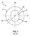
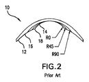
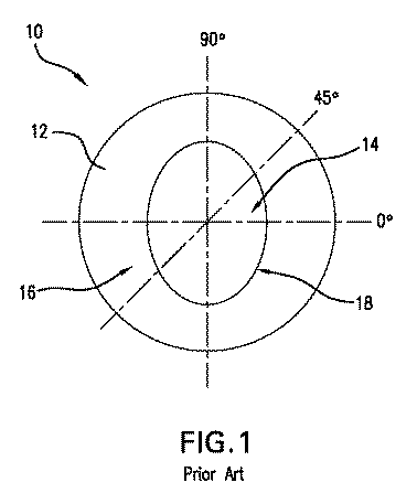
図1及び2は、従来技術のトーリックコンタクトレンズ10を示し、中央球円環状光学ゾーン14及び周辺球面ゾーン16を有する後面12を備える。これら2つのゾーン14及び16は、楕円を形成する接合部18で交わる。接合部では、後面12の傾斜が変化する。このことは図2に見ることができ、ここでは3つの経線R0、R45及びR90のすべてがともに重なり合い、R0は円柱経線であり、R90は球面経線であり、R45はそれらの間の中間の経線であり、傾斜は図示を目的として誇張されている。本図に示されるように、傾斜の変化は、R0経線に沿って最大になり、R90経線に沿って最小になる。すべての経線に沿って、後面12の傾斜は、接合部18で、中央ゾーン14での急傾斜から周辺ゾーン16で平坦に変化する。この急傾斜〜平坦な傾斜により、結果として接合部18で顕著な隆起となり、装用者の角膜に突き当たる。この隆起が角膜に圧力を加え、それによって装用者に炎症を起こさせる。また、比較的固い材料、たとえばシリコンハイドロゲル製のレンズでは、この圧力は結果として角膜上皮を汚染する可能性がある。
FIGS. 1 and 2 show a prior art
このように、トーリックレンズを改善し、快適さ及び目の健康のために、視力を犠牲にすることなく、レンズの角膜に対する改善された装着関係を提供する必要性が存在することがわかる。本発明は主として、そのような解決策を提供することに向けられる。 Thus, it can be seen that there is a need to improve the toric lens and provide an improved wearing relationship to the cornea of the lens without sacrificing visual acuity for comfort and eye health. The present invention is primarily directed to providing such a solution.
概して記載すると、本発明の一つの態様は、装用者の目の乱視矯正を助けるための眼用レンズを提供する。レンズは、中央光学ゾーンと、周辺ゾーンと、それらの間のブレンディングゾーンとを備える後面を有する。中央ゾーンの表面は球円環状であり、光軸からより遠くなるとより平坦になる傾斜を有する。また、周辺ゾーンの表面は非球面であり、光軸からより遠くなるとより平坦になる傾斜を有する。これらのより平坦な傾斜は、ゾーン間の移行をスムーズにし、目により良い装着を提供する。 Generally described, one aspect of the present invention provides an ophthalmic lens to aid in astigmatism correction in a wearer's eye. The lens has a back surface comprising a central optical zone, a peripheral zone, and a blending zone therebetween. The surface of the central zone is spherical and has a slope that becomes flatter further from the optical axis. Further, the surface of the peripheral zone is aspheric, and has a slope that becomes flatter as it is further from the optical axis. These flatter slopes smooth the transition between zones and provide better fit for the eyes.
加えて、ブレンディングゾーンは、中央及び周辺ゾーンの湾曲を徐々に移行して、中央〜周辺ゾーンの移行をさらにスムーズにする。本明細書に記載された実施形態の例では、中央及び周辺ゾーンの表面は、円柱軸と非球面軸との中間の経線に沿った中央ゾーンの曲線の延長を、周辺ゾーンの曲線の延長に全体的に一致させるように選択される。これにより、結果として傾斜は、対向しかつ大きさがほぼ同じである円柱軸及び球面軸に沿って変化する。本発明の範囲内に含まれる代替の実施形態は、中央及び周辺ゾーンの表面は、他の経線に沿ってゾーンの曲線が全体的に適合するように選択される。 In addition, the blending zone gradually transitions the curvature of the central and peripheral zones, making the transition from the central to the peripheral zones even smoother. In the example embodiment described herein, the surface of the central and peripheral zones is an extension of the curve of the central zone along the meridian intermediate between the cylinder axis and the aspherical axis, to the extension of the curve of the peripheral zone. Selected to match overall. As a result, the inclination changes along cylindrical and spherical axes that are opposite and of approximately the same size. An alternative embodiment included within the scope of the invention is that the surfaces of the central and peripheral zones are selected so that the curve of the zone generally fits along other meridians.
本発明の第1の実施形態の例では、中央ゾーンは非球体円環状及び円形であり、ブレンディングゾーンは一定の幅を有する円形帯であり、周辺ゾーンは非球面であり、一定の幅を有する円形帯である。ゾーンがすべて円形であることにより、レンズはより容易にモデリングされて製造され、目に快適である。 In the example of the first embodiment of the present invention, the central zone is aspherical and circular, the blending zone is a circular band with a constant width, the peripheral zone is aspheric and has a constant width. It is a circular band. Because the zones are all circular, the lens is more easily modeled and manufactured and is comfortable to the eyes.
第2の実施形態の例では、中央ゾーンは非球面円環状かつ楕円形であり、ブレンディングゾーンは一定の幅を有する楕円帯であり、周辺ゾーンは非球面である。中央ゾーンの楕円形状は、従来のトーリックレンズで提供されるものと同じである。 In the example of the second embodiment, the central zone is an aspherical annular and elliptical shape, the blending zone is an elliptical band having a certain width, and the peripheral zone is an aspherical surface. The elliptical shape of the central zone is the same as that provided by conventional toric lenses.
第3の実施形態の例では、中央ゾーンは非球面円環状かつ円形であり、ブレンディングゾーンは多様な幅を有する円形帯であり、周辺ゾーンは非球面である。ブレンディングゾーンは、傾斜の変化が最大になるところで(たとえば、非円柱形のR0経線及び非球面のR90経線で)最も広くなり、傾斜の変化が最小になるところで(たとえば、それらの中間点のR45経線で)最も狭くなる。 In the example of the third embodiment, the central zone is aspherical and circular, the blending zone is a circular band having various widths, and the peripheral zone is aspheric. The blending zone is widest where the change in slope is greatest (eg, with a non-cylindrical R0 meridian and a non-spherical R90 meridian) and where the change in slope is minimal (eg, R45 at their midpoint). Narrowest)
本発明の別の態様では、乱視矯正用レンズをデザインするための方法が提供される。本方法を用いて、本明細書に記載の、及び本発明の他の実施形態のレンズをデザインすることができる。デザイン方法は、レンズ面の中央ゾーンを定める工程と、レンズ面の周辺ゾーンを定める工程と、レンズ面のブレンディングゾーンを定める工程とを含む。中央及び周辺ゾーンを定める工程は、非球面円環状面及び非球面を定めることを含んでもよい。ブレンディングゾーンを定める工程は、たとえばスプライン機能を有する市販のCADソフトウェアパッケージを用いて、中央及び周辺ゾーンの曲線をブレンディングすることによって行われる。これは、中央及び周辺ゾーンの曲線の延長を、一つの経線(たとえば、R45経線)に沿って全体的に一致させた後、その他の経線に沿って曲線をブレンディングすることによって行われてもよい。結果として得られたレンズは、中央ゾーンと周辺ゾーンとの間のスムーズな移行を有し、目への圧力が著しく減少する。 In another aspect of the invention, a method for designing a lens for correcting astigmatism is provided. The method can be used to design lenses described herein and of other embodiments of the invention. The design method includes a step of defining a central zone of the lens surface, a step of defining a peripheral zone of the lens surface, and a step of defining a blending zone of the lens surface. Defining the central and peripheral zones may include defining an aspheric toric surface and an aspheric surface. The step of defining the blending zone is performed by blending the curves of the central and peripheral zones using, for example, a commercially available CAD software package having a spline function. This may be done by matching the extension of the curves in the central and peripheral zones generally along one meridian (eg, the R45 meridian) and then blending the curves along the other meridian. . The resulting lens has a smooth transition between the central and peripheral zones, and the pressure on the eye is significantly reduced.
本発明のこれら及び他の態様、特徴及び利点は、本明細書の図面及び詳細な説明を参照して理解され、添付の請求の範囲で特に指摘されたさまざまな要素及び組み合わせを用いて実現される。前述の発明の概要、及び以下に続く図面の簡単な説明及び本発明の詳細な説明の両方は、本発明の好ましい実施形態の代表的かつ説明的なものであり、主張されるように、本発明を限定するものではないことが理解されるべきである。 These and other aspects, features and advantages of the present invention will be realized using the various elements and combinations which are to be understood with reference to the drawings and detailed description herein, and which are particularly pointed out in the appended claims. The Both the foregoing summary of the invention and the following brief description of the drawings and detailed description of the invention are representative and explanatory of the preferred embodiments of the invention and, as claimed, are It should be understood that the invention is not limited.
本発明は、本開示の一部を形成する添付の図面に関連して得られた、以下に続く本発明の詳細な説明を参照することによって、より容易に理解され得る。本発明は、本明細書に記載された及び/又は示された具体的な装置、方法、条件又はパラメータに限定されず、本明細書で用いられた用語は、一例として特定の実施形態を記載することを目的とし、主張される本発明を限定することを意図しないことが理解されるべきである。また、特許請求の範囲を含む本明細書で用いられる限りでは、単数形「a」、「an」及び「the」は複数形を含み、特定の数値への言及は、状況的に明らかに示されない限り、少なくともその特定の値を含む。本明細書における範囲は、「約」又は「およそ」一つの特定の値から、及び/又は「約」又は「およそ」別の特定の値までとして表現される場合がある。そのような範囲が表現されたとき、別の実施形態は一つの特定の値から、及び/または一つの特定の値までを含む。同様に、値が先行詞「約」を用いて近似値として表現されると、特定の値は別の実施形態を形成することが理解される。 The present invention may be understood more readily by reference to the following detailed description of the invention, taken in conjunction with the accompanying drawings that form a part of this disclosure. The present invention is not limited to the specific apparatus, methods, conditions, or parameters described and / or shown herein, and the terminology used herein describes a particular embodiment as an example. It is to be understood that this is not intended to limit the claimed invention. Also, as used in this specification, including the claims, the singular forms “a”, “an”, and “the” include plural forms and references to specific numerical values are clearly indicated in the context. Unless specified, includes at least that particular value. Ranges herein may be expressed as from “about” or “approximately” one particular value and / or to “about” or “approximately” another particular value. When such a range is expressed, another embodiment includes from the one particular value and / or to the one particular value. Similarly, when values are expressed as approximations, using the antecedent “about,” it will be understood that the particular value forms another embodiment.
ここで図面を参照し、本発明のレンズの実施形態の例が示される。本発明のレンズは改善された後面デザインを有し、角膜に対するレンズの装着感を著しく改善する。本明細書に記載された実施形態の例では、レンズはコンタクトレンズであるが、後面デザインは別の眼用レンズで実施することもできる。レンズは従来眼用レンズで用いられている任意の材料で作ることができ、比較的固い材料、たとえばシリコンハイドロゲルを含み、従来の製造手法によって作ることができ、シングルポイントダイヤモンド切削システム、一面成型/一面ダイヤモンド切削システム、及び/又は両面成型システムを用いることによることを含む。 Referring now to the drawings, examples of lens embodiments of the present invention are shown. The lens of the present invention has an improved rear surface design, which significantly improves the lens fit on the cornea. In the example embodiments described herein, the lens is a contact lens, but the posterior design can also be implemented with another ophthalmic lens. The lens can be made of any material conventionally used in ophthalmic lenses, including relatively hard materials such as silicon hydrogel, and can be made by conventional manufacturing techniques, single point diamond cutting systems, single sided molding / By using a single-sided diamond cutting system and / or a double-sided molding system.
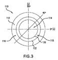
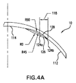
図3及び4は、第1の実施形態の例のトーリックコンタクトレンズ110を示す。レンズ110は後面112を有し、中央光学ゾーン114及び周辺ゾーン116を備える。前面は、レンズ100が装用される特定の目のために選択された光学矯正が備えられる。
3 and 4 show the
中央ゾーン114と周辺ゾーン116との間のスムーズな移行を提供して、これによってこれらのゾーンの接合部で突出する隆起を最小限にするか又は取り除くことを助けるために、後面112の周辺ゾーン116は非球面であり、中央ゾーン114は「非球面円環状(又はアトリック(atoric))である。本明細書で用いられる「非球面円環状」及び「アトリック」は、第1の経線(たとえばR0経線)に沿った円柱軸と、第2の垂直経線(たとえばR90経線)に沿った球面軸と、及び第1及び第2の経線の間の第3の経線(たとえばR45経線)に沿った、円柱軸及び球面軸の中間とを有することを意味し、表面の各経線は、円錐非球面方程式によって表され、円錐定数は、たとえば−1.0〜0.0の間である。「球面」軸及び「円柱」軸は、目の屈折誤差の矯正を参照し、経線の形状は参照しない。球面軸は球面度数を決定し、円柱軸は球面軸に対して垂直であり、円柱度数を決定する。そして、実際の臨床では、当業者は通常これらの軸を球面及び円柱と呼び、経線における曲線の形状が単一の半径を有するか、又は円錐セクションである、すなわち非球面であるかにかかわらない。
In order to provide a smooth transition between the
球面ゾーン116に関して、非球面は光軸を中心として回転対称であり、たとえば次式で表すことができる。
ここで、z及びxは座標であり(zはx軸からの距離であり、xはz軸(光軸)からの距離である)、cx=1/頂点半径xであり、kxは円錐定数であり、ここでたとえば−2.0<kx<0.0である。−1.0<kx<0.0の他の実施形態では、さらに別の−0.7<kx<−0.1の実施形態では、またさらなる別のkx=−0.16の実施形態では、非球面はこれらの実施形態において長円である。しかし、他のkx値を用いて、球面ゾーン116の他の非球面を定めてもよく、これはいくつかのケースに利益となる場合がある。当業者においては、非球面の「頂点半径」が、表面の頂点における半径であることが理解されよう。
With respect to the
Here, z and x are coordinates (z is a distance from the x-axis, x is a distance from the z-axis (optical axis)), cx = 1 / vertex radius x, and kx is a conic constant. Where, for example, −2.0 <kx <0.0. In other embodiments of −1.0 <kx <0.0, in yet another embodiment of −0.7 <kx <−0.1, and in yet another embodiment of kx = −0.16 The aspherical surface is an ellipse in these embodiments. However, other kx values may be used to define other aspheric surfaces of the
中央ゾーン114に関して、非球面円環面は、たとえば次式で表すことができる。
ここで、z、x及びyは座標であり(zはx軸及びy軸からの距離であり、xはy軸及びz軸からの距離であり、yはx軸及びz軸からの距離である)、cx=1/頂点半径xであり、cy=1/頂点半径yであり、kx及びkyはx軸及びy軸を基準とした円錐定数であり、ここでたとえば−2.0<kx<0.0及び−2.0<ky<0.0である。−1.0<kx<0.0及び−1.0<ky<0.0の他の実施形態では、さらに別の−0.7<kx<−0.1及び−0.7<ky<−0.1の実施形態では、またさらなる別のkx=ky=−0.16の実施形態では、非球面はこれらの実施形態において長円である。しかし、他のkx値及びky値を用いて、中央ゾーン114の他の非球面を定めてもよく、これはいくつかのケースに利益となる場合がある。加えて、円錐定数は、−1<kx<0及びこの範囲内でないkyで選択されてもよく、その反対でもよい。
For the
Here, z, x, and y are coordinates (z is a distance from the x-axis and the y-axis, x is a distance from the y-axis and the z-axis, and y is a distance from the x-axis and the z-axis. Cx = 1 / vertex radius x, cy = 1 / vertex radius y, and kx and ky are conic constants with respect to the x-axis and y-axis, where, for example, −2.0 <kx <0.0 and -2.0 <ky <0.0. In other embodiments of -1.0 <kx <0.0 and -1.0 <ky <0.0, additional -0.7 <kx <-0.1 and -0.7 <ky < In the -0.1 embodiment, and in yet another kx = ky = -0.16 embodiment, the aspheric surface is an ellipse in these embodiments. However, other kx and ky values may be used to define other aspheric surfaces of the
代替の実施形態では、中央ゾーン114は従来の球面円環面を有し、周辺ゾーン116は、本明細書で定義されたような非球面を有する。そして、他の代替の実施形態では、中央ゾーン114は、本明細書で定義されたような非球面円環面を有し、周辺ゾーン116は従来の球面を有する。しかし、そのような代替の実施形態では、R45経線に沿ってであってもゾーン間の傾斜変化があり、これが結果として突出して角膜上にいくらかの磨耗を生じさせる可能性がある。
In an alternative embodiment, the
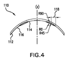
中央ゾーン114と周辺ゾーン116との間のスムーズな移行をさらに提供し、これによってこれらのゾーンの接合部で突出する隆起を最小限にするか又は取り除くことを助けるために、後面112は、中央ゾーン及び周辺ゾーン間にブレンディングゾーン118を含む。非球面円環状中央ゾーン114及び非球面周辺ゾーン116は、好ましくは、ブレンディングゾーン118の円柱軸及び球面軸間の経線(たとえばR45経線)に沿って、中央ゾーン面の曲線の延長124aが、周辺ゾーン面の曲線の延長124bに全体的に一致する(まさにその延長であるか、又はきわめて近似する)ように(円錐定数を選ぶことによって)選択される(図4A参照)。このように、中央ゾーン114と周辺ゾーン116との間には、傾斜変化がないか又はごくわずかのみになり、したがってブレンディングがないか又はごくわずかのみ行われる。
In order to further provide a smooth transition between the
R45経線に沿って、中央ゾーン114及び周辺ゾーン116の曲線面を全体的に一致させることによって、R0及びR90経線に沿った傾斜変化は、互いに向かい合い、ほぼ同じ大きさになる。そして、ブレンドされる傾斜変化量が最小限にされ、ブレンディングゾーンの幅が最小限にされる。球面軸(たとえばR90経線)に沿って、ブレンディングゾーン118のスプライン曲線128は、中央ゾーン114から周辺ゾーン116へ、平坦から急傾斜へと徐々に変化する。そして、実際にはブレンディングゾーン118の表面112には、中央から周辺ゾーンへの移行の結果として形成されるくぼみがあり、従来のトーリックレンズの鋭く突出した隆起に代わって、くぼみは軽微かつスムーズである。そして、円柱軸(たとえばR0経線)に沿って、ブレンディングゾーン118のスプライン曲線126は、中央ゾーン114から周辺ゾーン116へ、急傾斜から平坦へと徐々に変化する(その結果、R90経線に沿った傾斜変化に反する)。そして、中央から周辺ゾーンへの移行の結果としての軽微かつスムーズな膨らみのみがあり、移行は従来のトーリックレンズの鋭く突出した隆起よりもかなりスムーズである。
By making the curved surfaces of the
代替の実施形態では、非球面円環状中央ゾーン及び非球面周辺ゾーンは、ブレンディングゾーンの円柱軸(たとえばR0経線)に沿って、中央ゾーン面の曲線の延長が、周辺ゾーン面の曲線の延長に全体的に一致する(まさにその延長であるか、又はきわめて近似する)ように構成される。このように、R0経線に沿って(R45経線に沿うことに代えて)、中央ゾーンと周辺ゾーンとの間に傾斜変化がないか又はごくわずかのみになり、結果としてその経線に沿っては膨らみがないかまたはごくわずかのみになる。そして、R45及びR90経線に沿って、傾斜は中央ゾーンから周辺ゾーンへ、平坦から急傾斜に変化し、これによってブレンディングゾーンの後面にくぼみが形成される。このように、本実施形態では、装用者の角膜に装用する膨らみ又は隆起が無くなるかほとんどなくなる。しかし、本実施形態では、レンズをより厚くして、R90経線におけるくぼみが最も深くなるところでの許容し得ない薄弱なスポットを回避する必要がある。そして、より大きな傾斜変化をブレンドするため、ブレンディングゾーン118はより幅広くする必要があるかもしれない。
In an alternative embodiment, the aspheric annular central zone and the aspheric peripheral zone may be configured such that, along the cylindrical axis of the blending zone (eg, R0 meridian), the extension of the curve of the central zone surface becomes the extension of the curve of the peripheral zone surface. It is configured to be entirely consistent (exactly or very close to it). Thus, along the R0 meridian (instead of along the R45 meridian), there is little to no change in slope between the central zone and the peripheral zone, resulting in a bulge along that meridian. There is no or very little. Then, along the R45 and R90 meridians, the slope changes from a flat zone to a steep slope from the central zone to the peripheral zone, thereby forming a recess in the rear surface of the blending zone. Thus, in this embodiment, there is no or almost no bulge or bulge worn on the wearer's cornea. However, in this embodiment, it is necessary to make the lens thicker to avoid an unacceptable weak spot where the indentation in the R90 meridian is deepest. And blending
他の代替の実施形態では、R0及びR90経線間の他の経線が選択されて、中央ゾーン及び周辺ゾーンの曲線を全体的に一致させる。たとえば、R35及びR55経線間の任意の経線に沿って中央ゾーン及び周辺ゾーンの曲線を全体的に一致させることは、良好な結果をもたらす。さらに他の代替の実施形態では、いずれの経線も全体的に一致させず、各経線に沿ってブレンドされた傾斜変化がある。しかし、これらの実施形態では、傾斜変化がより大きくなると、より幅広いブレンディングゾーンで曲線をブレンドする必要が生じる場合がある。そして、さらなる他の代替の実施形態では、中央ゾーンは従来の円環状面であり、周辺ゾーンは従来の球面であり、ブレンディングゾーンは中央ゾーンと周辺ゾーンをともにスムーズに移行させる。 In other alternative embodiments, other meridians between the R0 and R90 meridians are selected to generally match the curves in the central and peripheral zones. For example, matching the curves of the central and peripheral zones generally along any meridian between the R35 and R55 meridians yields good results. In yet another alternative embodiment, none of the meridians are generally coincident and there is a slope change blended along each meridian. However, in these embodiments, the greater the slope change, it may be necessary to blend the curves in a wider blending zone. And in yet another alternative embodiment, the central zone is a conventional annular surface, the peripheral zone is a conventional spherical surface, and the blending zone smoothly transitions between the central zone and the peripheral zone.
本実施形態のレンズ110では、ブレンディングゾーン118は円形帯であり、たとえば約0.2mm〜1.0mmの一定の幅を有してもよい。中央ゾーン114が円形帯であり、光学ゾーンであるため、たとえば直径約7mm以上を有していてもよく、これは通常の成人の導孔が微小光下で達する大きさとほぼ同じである。このように、ブレンディングゾーン118の内部境界120は、たとえば直径約7mm以上を有し、レンズ110の光学に干渉しないようにしてもよい。そして、ブレンディングゾーン118の外部境界122は、たとえば直径約8.2mm〜約9.0mmを有していてもよい。
In the
レンズ110の周辺ゾーン116は、一定の幅を有する円形帯(すなわち、レンズの中央線を中心に回転対称)であり、レンズの周辺で厚さプロファイルを変化させることなく、基礎曲線型を回転させることによって形成することができる。円形帯の別の利点は、製造が容易であることである。さらに、一定の幅及び厚さの周辺ゾーン116は一般に、快適な装着及び臨床性能のために好ましい。これらの理由から、レンズ110は、好ましくは、外に向かってレンズの外縁まで延びるブレンディングゾーン116を有することに代えて、周辺ゾーン116を含む。周辺ゾーン116は、たとえば約1.0mm〜約3.5mmの一定の幅を有していてもよい。
The
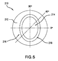
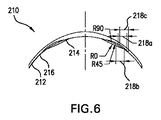
図5及び6は、第2の実施形態の例のトーリックコンタクトレンズ210を示す。レンズ210は、第1の実施形態のレンズ110に類似し、中央非球面円環状光学ゾーン214、周辺非球面ゾーン216、及びそれらの間のブレンディングゾーン218を備える後面212を有する。しかし、本実施形態では、中央ゾーン214は(従来のトーリックレンズのように)楕円であり、ブレンディングゾーン218は楕円帯である。図6は、R45経線におけるブレンディングゾーンセクション218aと、R0経線におけるブレンディングゾーンセクション218bと、R90経線におけるブレンディングゾーンセクション218とを示す。R0経線における中央ゾーン214の直径は、普通は円柱度数によって決定され、すなわち、より大きな円柱係数はより大きな直径を有する。中央ゾーン214の最小直径は、たとえばR0経線で約7.0mmにしてもよく、最大直径は、たとえばR90経線で約12.5mmにしてもよい。ブレンディングゾーン118は、たとえば約0.2mm〜約1.0mmの一定の幅を有していてもよい。そして、周辺ゾーン216は、たとえばR90経線で最小幅約1.0mm、たとえばR0経線で最大幅約3.5mmを有していてもよい。
5 and 6 show a
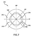
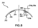
図7及び8は、第3の実施形態の例のトーリックコンタクトレンズ310を示す。レンズ310は、第1の実施形態のレンズ110に類似し、中央非球面円環状光学ゾーン314、周辺非球面ゾーン316、及びそれらの間のブレンディングゾーン318を備える後面312を有する。しかし、本実施形態では、ブレンディングゾーン318は多様な幅を有する。ブレンディングゾーン318は、傾斜変化が最大になるところで(たとえば、円柱形のR0経線及び球面のR90経線で)もっとも幅広くなり、ブレンドされている曲線間のスムーズな移行のために十分な距離を与える。そして、ブレンディングゾーン318は、傾斜変化が最小になるところで(たとえば、R0経線とR90経線との中間、R45経線で)最も狭くなるが、これはスムーズな移行は、より短い距離でなされることができるためである。ブレンディングゾーン318は、R45経線で少なくともいくつかの幅を備え、従来のコンピュータ支援デザイン(CAD)ソフトウェアを用いたブレンディングを容易にする。ブレンディングゾーン318の最小幅は、たとえばR0及びR90経線で約0.2mmにしてもよく、最大幅は、たとえばR45経線で約1.0mmにしてもよい。本明細書で述べるように、中央ゾーン314は、たとえば少なくとも直径約7.0mmを有し、レンズの光学に干渉しないようにしてもよい。そして、ブレンディングゾーン幅の多様性は、外部境界322の変動性の結果である。本実施形態は、ブレンドされる曲線をより均一に移行させる傾向にあるが、ブレンディングゾーン318の幅の変動性のために、本レンズのモデリングはより困難になる傾向にある。多様な幅のブレンディングゾーンはまた、楕円の中央ゾーンを備えるレンズで実施されることもできることが理解されよう。
7 and 8 show a
本発明の別の実施形態では、本発明の実施形態の例及び他の実施形態のレンズをデザインする方法が提供される。本方法は、汎用パーソナルコンピュータ、たとえばデスクトップ、ラップトップ又は携帯型コンピュータに格納された市販のCADソフトウェアパッケージを用いて行われてもよい。CADソフトウェアパッケージは、スプライン関数を付与してスプライン曲線を生成し、中央及び周辺ゾーンの曲線をブレンドするための特徴を含む。本方法で用いることができる市販のプログラムは、SolidWorks Corporation(Condord,MA)より商標名「SOLIDWORKS」で販売されているもの、Parametric Technology Corporation (Needham, MA)の「PRO/ENGINEER」、及びAutodesk,Inc.(San Rafael, CA)の「AUTOCAD」を含む。 In another embodiment of the invention, an example embodiment of the invention and a method for designing a lens of another embodiment are provided. The method may be performed using a commercially available CAD software package stored on a general purpose personal computer such as a desktop, laptop or portable computer. The CAD software package includes features for applying spline functions to generate spline curves and blending the curves in the central and peripheral zones. Commercially available programs that can be used in this method include those sold under the trade name “SOLIDWORKS” by SolidWorks Corporation (Cordord, Mass.), “PRO / ENGINEER” of Parametric Technology Corporation (Needham, Mass.), And Autod. Inc. (San Rafael, CA) "AUTOCAD".
デザイン方法は、後面の中央ゾーンを定める工程と、後面の周辺ゾーンを定める工程と、中央ゾーン及び周辺ゾーンの曲線を、スプライン関数を用いてブレンディングゾーンでブレンディングする工程とを含む。中央ゾーンは、本明細書に記載された非球面円環状面によって定められてもよく、本明細書に記載されたような平面形状及び寸法を有していてもよい。周辺ゾーンは、本明細書に記載された非球面によって定められてもよく、本明細書に記載されたような平面形状及び寸法を有していてもよい。中央ゾーン及び周辺ゾーンの表面をブレンドするために、一つの経線に沿った中央ゾーンの曲線の延長は、周辺ゾーンの曲線の延長に全体的に一致する。そして、CADプログラムのスプライン関数を用いて、各経線に沿った中央ゾーン及び周辺ゾーンの曲線がともにブレンドされる。たとえば、R45経線に沿って曲線を全体的に一致させることによって、R0及びR90に沿った傾斜変化は、互いに向き合ってほぼ同じ大きさを有する。これに代えて、本方法は、R0及びR90経線間の別の経線、たとえばR35及びR55経線間の任意の経線に沿って、曲線を全体的に一致させることを含んでもよい。結果として得られるレンズの後面は、中央ゾーンと周辺ゾーンとの間でスムーズな移行を有し、移行部分に軽微かつスムーズな膨らみのみを有するため、装用者の目にかかるレンズ圧力を大幅に減少させる。 The design method includes a step of defining a central zone on the rear surface, a step of defining a peripheral zone on the rear surface, and a step of blending the curves of the central zone and the peripheral zone in the blending zone using a spline function. The central zone may be defined by the aspheric toric surface described herein and may have a planar shape and dimensions as described herein. The peripheral zone may be defined by the aspheric surfaces described herein and may have a planar shape and dimensions as described herein. In order to blend the surface of the central zone and the peripheral zone, the extension of the curve of the central zone along one meridian generally matches the extension of the curve of the peripheral zone. Then, using the spline function of the CAD program, the curves of the central zone and the peripheral zone along each meridian are blended together. For example, by matching the curves generally along the R45 meridian, the slope changes along R0 and R90 face each other and have approximately the same magnitude. Alternatively, the method may include generally matching the curves along another meridian between the R0 and R90 meridians, such as any meridian between the R35 and R55 meridians. The resulting rear surface of the lens has a smooth transition between the central and peripheral zones and only a slight and smooth bulge at the transition, greatly reducing lens pressure on the wearer's eyes Let
好ましい実施形態の例を参照して本発明を説明してきたが、当業者においては、各種の変更、付加及び削除は、以下に続く特許請求の範囲で定義されたような本発明の範囲内であることが理解されよう。 Although the invention has been described with reference to preferred embodiment examples, those skilled in the art will recognize that various modifications, additions and deletions are within the scope of the invention as defined in the following claims. It will be understood that there is.
Claims (24)
非球面円環状の中央ゾーンであって、次式
で表すことができ、z、x及びyは、それぞれz軸、x軸及びy軸を基準とした座標であり、cx=1/頂点半径xであり、cy=1/頂点半径yであり、kx及びkyはそれぞれx軸及びy軸を基準とした円錐定数であり、−2.0<kx<0.0及び−2.0<ky<0.0である中央ゾーンと、
非球面の周辺ゾーンであって、z軸を中心として回転対称であり、次式
で表すことができ、z及びxは、それぞれz軸及びx軸を基準とした座標であり、cx=1/頂点半径xであり、kxは円錐定数であり、−2.0<kx<0.0である中央ゾーンと、
非球面円環状中央ゾーン及び非球面周辺ゾーンの間のスムーズな移行を形成し、スプライン曲線によって少なくとも部分的に表されるブレンディングゾーンであって、円柱経線及び球面経線に沿って、ブレンディングゾーンのスプライン曲線の傾斜変化が向き合い、ほぼ同じ大きさであり、円柱経線及び球面経線の中間の経線に沿って、ブレンディングゾーン内で中央ゾーンの延長が、周辺ゾーンの延長と全体的に一致するブレンディングゾーンと、
を含む眼用レンズ。 A rear surface having a central optical zone, a peripheral zone and a blending zone between them;
Aspherical central zone with the following formula
Z, x, and y are coordinates based on the z-axis, x-axis, and y-axis, respectively, cx = 1 / vertex radius x, cy = 1 / vertex radius y, kx and ky are conic constants with respect to the x-axis and y-axis, respectively, and a central zone where −2.0 <kx <0.0 and −2.0 <ky <0.0;
An aspherical peripheral zone that is rotationally symmetric about the z-axis.
Z and x are coordinates based on the z axis and the x axis, respectively, cx = 1 / vertex radius x, kx is a conic constant, and −2.0 <kx <0. A central zone that is .0;
A blending zone that forms a smooth transition between an aspheric annular central zone and an aspheric peripheral zone and is at least partially represented by a spline curve, the spline of the blending zone along the cylindrical and spherical meridians A blending zone in which the slope changes of the curves face and are approximately the same size, and the extension of the central zone within the blending zone is generally coincident with the extension of the surrounding zone, along the meridian between the cylindrical and spherical meridians ,
Including ophthalmic lenses.
レンズ後面の非球面周辺ゾーンを定めることと、
スプライン曲線を生成させて、非球面円環状中央ゾーンと非球面周辺ゾーンとの間の移行をスムーズにすることによって、レンズ面のブレンディングゾーンを定めることと、
を含む、請求項1記載のレンズをデザインする方法。 Defining a rear aspherical annular central zone;
Defining an aspheric peripheral zone on the rear surface of the lens;
Defining a blending zone for the lens surface by generating a spline curve and smoothing the transition between the aspheric annular central zone and the aspheric peripheral zone;
A method of designing a lens according to claim 1 comprising:
乱視を矯正するように構成された中央ゾーンと、
中央ゾーン及び周辺ゾーンの間のスムーズな移行を形成し、スプライン曲線によって少なくとも部分的に表されるブレンディングゾーンと、
を含む眼用レンズ。 A rear surface having a central optical zone, a peripheral zone, and a blending zone therebetween,
A central zone configured to correct astigmatism;
A blending zone that forms a smooth transition between the central and peripheral zones and is at least partially represented by a spline curve;
Including ophthalmic lenses.
スプライン曲線を生成させて中央ゾーン及び周辺ゾーンの間の移行をスムーズにすることによって、レンズ面のブレンディングゾーンを定めることと、
を含む、請求項6記載のレンズをデザインする方法。 Defining a central zone and a spherical zone on the rear surface of the lens;
Defining a blending zone for the lens surface by generating a spline curve to smooth the transition between the central and peripheral zones;
A method for designing a lens according to claim 6 comprising:
ブレンディングゾーンを定める工程が、中央ゾーン、周辺ゾーン又は中央及び周辺ゾーンの円錐定数を選択して、第1の円柱経線及び第2の球面経線に沿って、ブレンディングゾーンのスプライン曲線の傾斜変化が互いに向き合い、ブレンディングゾーンの第1及び第2の経線間のいずれかの位置の第3の経線に沿って、中央ゾーンの延長が周辺ゾーンの延長に全体的に一致することを含む、請求項16記載の方法。 The step of defining the central zone and the peripheral zone includes the step of forming the central zone as an aspherical ring and the peripheral zone as a spherical surface, the central zone as a spherical ring and a peripheral zone as aspherical surface, Including defining an aspheric surface,
The step of defining a blending zone selects a central zone, a peripheral zone, or a conic constant of the central and peripheral zones, and along the first cylindrical meridian and the second spherical meridian, the slope changes of the blending zone spline curves are The central zone extension generally coincides with the peripheral zone extension along the third meridian at any location between the first and second meridians of the facing and blending zones. the method of.
で表され、z、x及びyは、それぞれz軸、x軸及びy軸を基準とした座標であり、cx=1/頂点半径xであり、cy=1/頂点半径yであり、kx及びkyはそれぞれx軸及びy軸を基準とした円錐定数であり、−2.0<kx<0.0及び−2.0<ky<0.0であり、
非球面の周辺ゾーンが、z軸を中心として回転対称であり、次式
で表すことができ、z及びxは、それぞれz軸及びx軸を基準とした座標であり、cx=1/頂点半径xであり、kxは円錐定数であり、−2.0<kx<0.0である、請求項18記載のレンズ。 The central aspherical annular zone is
Z, x and y are coordinates based on the z-axis, x-axis and y-axis, respectively, cx = 1 / vertex radius x, cy = 1 / vertex radius y, kx and ky is a conic constant based on the x axis and the y axis, respectively, −2.0 <kx <0.0 and −2.0 <ky <0.0,
The aspheric peripheral zone is rotationally symmetric about the z-axis,
Z and x are coordinates based on the z axis and the x axis, respectively, cx = 1 / vertex radius x, kx is a conic constant, and −2.0 <kx <0. The lens of claim 18, which is 0.0.
Applications Claiming Priority (3)
| Application Number | Priority Date | Filing Date | Title |
|---|---|---|---|
| US95433907P | 2007-08-07 | 2007-08-07 | |
| US60/954,339 | 2007-08-07 | ||
| PCT/US2008/072213 WO2009020963A1 (en) | 2007-08-07 | 2008-08-05 | Toric contact lens with improved posterior surface design |
Publications (2)
| Publication Number | Publication Date |
|---|---|
| JP2010536070A true JP2010536070A (en) | 2010-11-25 |
| JP5831865B2 JP5831865B2 (en) | 2015-12-09 |
Family
ID=39829027
Family Applications (1)
| Application Number | Title | Priority Date | Filing Date |
|---|---|---|---|
| JP2010520260A Active JP5831865B2 (en) | 2007-08-07 | 2008-08-05 | Toric lens with improved rear design |
Country Status (6)
| Country | Link |
|---|---|
| US (1) | US7625085B2 (en) |
| EP (1) | EP2176702B1 (en) |
| JP (1) | JP5831865B2 (en) |
| KR (1) | KR101547372B1 (en) |
| CA (1) | CA2695516C (en) |
| WO (1) | WO2009020963A1 (en) |
Cited By (1)
| Publication number | Priority date | Publication date | Assignee | Title |
|---|---|---|---|---|
| KR20220066329A (en) * | 2019-09-25 | 2022-05-24 | 엔탈믹 홀딩 피티와이 리미티드 | Contact Lens Solutions for Myopia Management |
Families Citing this family (32)
| Publication number | Priority date | Publication date | Assignee | Title |
|---|---|---|---|---|
| JP4942762B2 (en) * | 2005-12-22 | 2012-05-30 | ボシュ・アンド・ロム・インコーポレイテッド | Toric contact lens |
| US9216080B2 (en) | 2007-08-27 | 2015-12-22 | Amo Groningen B.V. | Toric lens with decreased sensitivity to cylinder power and rotation and method of using the same |
| US8974526B2 (en) | 2007-08-27 | 2015-03-10 | Amo Groningen B.V. | Multizonal lens with extended depth of focus |
| ATE523810T1 (en) | 2008-02-15 | 2011-09-15 | Amo Regional Holdings | SYSTEM, GLASS LENS AND METHOD FOR EXPANDING THE DEPTH OF FOCUS |
| US8439498B2 (en) | 2008-02-21 | 2013-05-14 | Abbott Medical Optics Inc. | Toric intraocular lens with modified power characteristics |
| US8862447B2 (en) | 2010-04-30 | 2014-10-14 | Amo Groningen B.V. | Apparatus, system and method for predictive modeling to design, evaluate and optimize ophthalmic lenses |
| US8113652B2 (en) | 2009-03-27 | 2012-02-14 | Crt Technology, Inc. | Contact lens with meridional sagittal variation and methods for making and using the same |
| CA2784782C (en) | 2009-12-18 | 2018-02-27 | Hendrik A. Weeber | Limited echelette lens, systems and methods |
| US8256896B2 (en) | 2010-02-25 | 2012-09-04 | Abbott Medical Optic Inc. | Toric optic for ophthalmic use |
| EP3330776A1 (en) | 2010-12-01 | 2018-06-06 | AMO Groningen B.V. | A multifocal lens having an optical add power progression, and a system and method of providing same |
| EP2928413B1 (en) | 2012-12-04 | 2019-08-14 | AMO Groningen B.V. | Lenses systems and methods for providing binocular customized treatments to correct presbyopia |
| US9421721B2 (en) | 2013-09-20 | 2016-08-23 | Gregory Gemoules | System and method for designing scleral lenses |
| EP3413840A1 (en) | 2016-02-09 | 2018-12-19 | AMO Groningen B.V. | Progressive power intraocular lens, and methods of use and manufacture |
| AU2017238517B2 (en) | 2016-03-23 | 2021-11-11 | Johnson & Johnson Surgical Vision, Inc. | Ophthalmic apparatus with corrective meridians having extended tolerance band |
| US11123178B2 (en) | 2016-03-23 | 2021-09-21 | Johnson & Johnson Surgical Vision, Inc. | Power calculator for an ophthalmic apparatus with corrective meridians having extended tolerance or operation band |
| WO2018078439A2 (en) | 2016-10-25 | 2018-05-03 | Amo Groningen B.V. | Realistic eye models to design and evaluate intraocular lenses for a large field of view |
| WO2018112558A1 (en) * | 2016-12-23 | 2018-06-28 | Capricornia Contact Lens Pty Ltd | Contact lens |
| US10739227B2 (en) | 2017-03-23 | 2020-08-11 | Johnson & Johnson Surgical Vision, Inc. | Methods and systems for measuring image quality |
| US20190064543A1 (en) * | 2017-08-30 | 2019-02-28 | Johnson & Johnson Vision Care, Inc. | Atoric Surfaces to Minimize Secondary Astigmatism in Contact Lenses for the Correction of Astigmatism |
| KR20190052856A (en) | 2017-11-09 | 2019-05-17 | (주)에이지광학 | Axis asymmetric and aspherical glass lens with large aparture |
| WO2019106067A1 (en) | 2017-11-30 | 2019-06-06 | Amo Groningen B.V. | Intraocular lenses that improve post-surgical spectacle independent and methods of manufacturing thereof |
| US11886046B2 (en) | 2019-12-30 | 2024-01-30 | Amo Groningen B.V. | Multi-region refractive lenses for vision treatment |
| KR20210085583A (en) * | 2019-12-31 | 2021-07-08 | 주식회사 인터로조 | Contact Lenses with Spherical Aberration Control Design for Improved Visual Performance |
| US20230123284A1 (en) * | 2020-02-14 | 2023-04-20 | Nthalmic Holding Pty Ltd | A contact lens for myopia with or without astigmatism |
| KR20260004583A (en) | 2021-03-03 | 2026-01-08 | 쉔양칸겐더메디컬사이언스앤드테크놀로지씨오엘티디 | Geometric volume control corneal refractive therapy contact lens |
| ES2998813T3 (en) * | 2021-04-29 | 2025-02-21 | Coopervision Int Ltd | Lens sets for use in preventing or slowing the development or progression of myopia and related methods |
| EP4333685B1 (en) | 2021-05-05 | 2026-01-14 | AMO Groningen B.V. | Ring halometer system and method for quantifying dysphotopsias |
| US12544218B2 (en) | 2021-12-03 | 2026-02-10 | Amo Groningen B.V. | Lenses having multi-ring design for vision treatment |
| CN114740635B (en) * | 2022-04-22 | 2024-07-26 | 温州视铂科技有限公司 | Four-quadrant asymmetric cornea shaping mirror |
| CN118871065B (en) * | 2022-12-02 | 2025-04-08 | 深圳市新产业眼科新技术有限公司 | Enhanced ophthalmic lens with singular aspheric axicon refractive optics |
| US20250102829A1 (en) * | 2023-09-27 | 2025-03-27 | Johnson & Johnson Vision Care, Inc. | Optimized Posterior Surface for Toric Contact Lenses |
| TWI853722B (en) * | 2023-09-28 | 2024-08-21 | 視陽光學股份有限公司 | Contact lens |
Citations (3)
| Publication number | Priority date | Publication date | Assignee | Title |
|---|---|---|---|---|
| JPH1138368A (en) * | 1997-03-31 | 1999-02-12 | Johnson & Johnson Vision Prod Inc | Process for producing composite optical face on soft contact lens |
| JP2005534966A (en) * | 2002-07-31 | 2005-11-17 | ノバルティス アクチエンゲゼルシャフト | Toric multifocal contact lens |
| WO2007075975A2 (en) * | 2005-12-22 | 2007-07-05 | Bausch & Lomb Incorporated | Toric contact lenses |
Family Cites Families (18)
| Publication number | Priority date | Publication date | Assignee | Title |
|---|---|---|---|---|
| US4418991A (en) * | 1979-09-24 | 1983-12-06 | Breger Joseph L | Presbyopic contact lens |
| US5009497A (en) * | 1987-11-12 | 1991-04-23 | Cohen Allen L | Contact lenses utilizing keel orientation |
| US5020898A (en) * | 1990-01-29 | 1991-06-04 | Schering Corporation | Contact lens for correction of astigmatism |
| US5767939A (en) * | 1991-10-09 | 1998-06-16 | Seiko Epson Corporation | Eyeglass lens |
| TW210380B (en) * | 1992-04-23 | 1993-08-01 | Ciba Geigy Ag | |
| US5650838A (en) * | 1995-05-04 | 1997-07-22 | Johnson & Johnson Vision Products, Inc. | Programmable smooth junctions on lenses |
| IL118065A0 (en) * | 1995-05-04 | 1996-08-04 | Johnson & Johnson Vision Prod | Aspheric toric lens designs |
| US6241355B1 (en) * | 1996-03-29 | 2001-06-05 | Brian A. Barsky | Computer aided contact lens design and fabrication using spline surfaces |
| US6000798A (en) * | 1997-10-06 | 1999-12-14 | Innotech Inc. | Ophthalmic optic devices |
| AUPP016197A0 (en) * | 1997-11-03 | 1997-11-27 | Sola International Holdings Ltd | Improved ophthalmic lens |
| US6176577B1 (en) * | 1998-10-15 | 2001-01-23 | Oracle Lens Manufacturing Corporation | Aspheric lenses |
| US6142627A (en) * | 1998-12-01 | 2000-11-07 | Sola International, Inc. | Short-corridor progressive lens |
| US6582076B1 (en) * | 2000-08-30 | 2003-06-24 | Johnson & Johnson Vision Care, Inc. | Ophthalmic lenses useful in correcting astigmatism and presbyopia |
| US6843563B2 (en) * | 2002-07-31 | 2005-01-18 | Bausch And Lomb, Inc. | Smoothly blended optical surfaces |
| US7036931B2 (en) * | 2003-01-29 | 2006-05-02 | Novartis Ag | Ophthalmic lenses |
| US7004585B2 (en) * | 2003-02-11 | 2006-02-28 | Novartis Ag | Ophthalmic lens having an optical zone blend design |
| US20050041203A1 (en) * | 2003-08-20 | 2005-02-24 | Lindacher Joseph Michael | Ophthalmic lens with optimal power profile |
| ES2527284T3 (en) * | 2005-08-24 | 2015-01-22 | Hecht Contactlinsen Gmbh | Contact lens stably |
-
2008
- 2008-08-05 US US12/221,566 patent/US7625085B2/en active Active
- 2008-08-05 EP EP08797189.1A patent/EP2176702B1/en active Active
- 2008-08-05 JP JP2010520260A patent/JP5831865B2/en active Active
- 2008-08-05 WO PCT/US2008/072213 patent/WO2009020963A1/en not_active Ceased
- 2008-08-05 CA CA2695516A patent/CA2695516C/en active Active
- 2008-08-05 KR KR1020107004937A patent/KR101547372B1/en active Active
Patent Citations (3)
| Publication number | Priority date | Publication date | Assignee | Title |
|---|---|---|---|---|
| JPH1138368A (en) * | 1997-03-31 | 1999-02-12 | Johnson & Johnson Vision Prod Inc | Process for producing composite optical face on soft contact lens |
| JP2005534966A (en) * | 2002-07-31 | 2005-11-17 | ノバルティス アクチエンゲゼルシャフト | Toric multifocal contact lens |
| WO2007075975A2 (en) * | 2005-12-22 | 2007-07-05 | Bausch & Lomb Incorporated | Toric contact lenses |
Cited By (4)
| Publication number | Priority date | Publication date | Assignee | Title |
|---|---|---|---|---|
| KR20220066329A (en) * | 2019-09-25 | 2022-05-24 | 엔탈믹 홀딩 피티와이 리미티드 | Contact Lens Solutions for Myopia Management |
| JP2022549903A (en) * | 2019-09-25 | 2022-11-29 | エヌサルミック ホールディング ピーティーワイ リミテッド | Contact lens solutions for myopia management |
| JP7597797B2 (en) | 2019-09-25 | 2024-12-10 | エヌサルミック ホールディング ピーティーワイ リミテッド | Contact Lens Solutions for Myopia Management |
| KR102899861B1 (en) * | 2019-09-25 | 2025-12-15 | 엔탈믹 홀딩 피티와이 리미티드 | Contact lens solutions for myopia management |
Also Published As
| Publication number | Publication date |
|---|---|
| CA2695516A1 (en) | 2009-02-12 |
| WO2009020963A1 (en) | 2009-02-12 |
| KR101547372B1 (en) | 2015-08-25 |
| EP2176702A1 (en) | 2010-04-21 |
| KR20100040958A (en) | 2010-04-21 |
| CA2695516C (en) | 2016-02-16 |
| US20090040458A1 (en) | 2009-02-12 |
| US7625085B2 (en) | 2009-12-01 |
| JP5831865B2 (en) | 2015-12-09 |
| EP2176702B1 (en) | 2020-07-08 |
Similar Documents
| Publication | Publication Date | Title |
|---|---|---|
| JP5831865B2 (en) | Toric lens with improved rear design | |
| US8020990B2 (en) | System and method of surfacing a lens, such as a lens for use with eyeglasses | |
| JP5448789B2 (en) | Toric contact lens and manufacturing method thereof | |
| CN102449535B (en) | Contact lens with meridional sagittal variation and methods for making and using same | |
| JP4580446B2 (en) | Contact lens manufacturing method | |
| US6733124B2 (en) | Contact lens | |
| EP3865930B1 (en) | Ophthalmic lens, design method for same, manufacturing method for same, and ophthalmic lens set | |
| NZ543773A (en) | Contact lens with shaped periphery | |
| TW201326960A (en) | Method for designing non-round soft contact lenses | |
| TWI686640B (en) | Contact lens with optimized performance and method of design | |
| KR102659759B1 (en) | Rotationally stabilized contact lens with improved comfort and method of optimization | |
| CN110618540B (en) | Rotationally stabilized non-truncated contact lenses | |
| JP4298515B2 (en) | Contact lens having an eccentric spherical surface | |
| TW201809808A (en) | Progressive multifocal contact lens and producing method thereof | |
| CN114206263A (en) | Intraocular lens with extended depth of focus |
Legal Events
| Date | Code | Title | Description |
|---|---|---|---|
| A621 | Written request for application examination |
Free format text: JAPANESE INTERMEDIATE CODE: A621 Effective date: 20110608 |
|
| A977 | Report on retrieval |
Free format text: JAPANESE INTERMEDIATE CODE: A971007 Effective date: 20130315 |
|
| A131 | Notification of reasons for refusal |
Free format text: JAPANESE INTERMEDIATE CODE: A131 Effective date: 20130604 |
|
| A601 | Written request for extension of time |
Free format text: JAPANESE INTERMEDIATE CODE: A601 Effective date: 20130827 |
|
| A602 | Written permission of extension of time |
Free format text: JAPANESE INTERMEDIATE CODE: A602 Effective date: 20130903 |
|
| A521 | Request for written amendment filed |
Free format text: JAPANESE INTERMEDIATE CODE: A523 Effective date: 20131003 |
|
| A02 | Decision of refusal |
Free format text: JAPANESE INTERMEDIATE CODE: A02 Effective date: 20140107 |
|
| RD04 | Notification of resignation of power of attorney |
Free format text: JAPANESE INTERMEDIATE CODE: A7424 Effective date: 20140726 |
|
| RD04 | Notification of resignation of power of attorney |
Free format text: JAPANESE INTERMEDIATE CODE: A7424 Effective date: 20150304 |
|
| A521 | Request for written amendment filed |
Free format text: JAPANESE INTERMEDIATE CODE: A523 Effective date: 20150828 |
|
| A61 | First payment of annual fees (during grant procedure) |
Free format text: JAPANESE INTERMEDIATE CODE: A61 Effective date: 20151020 |
|
| R150 | Certificate of patent or registration of utility model |
Ref document number: 5831865 Country of ref document: JP Free format text: JAPANESE INTERMEDIATE CODE: R150 |
|
| S531 | Written request for registration of change of domicile |
Free format text: JAPANESE INTERMEDIATE CODE: R313531 |
|
| R360 | Written notification for declining of transfer of rights |
Free format text: JAPANESE INTERMEDIATE CODE: R360 |
|
| R360 | Written notification for declining of transfer of rights |
Free format text: JAPANESE INTERMEDIATE CODE: R360 |
|
| R371 | Transfer withdrawn |
Free format text: JAPANESE INTERMEDIATE CODE: R371 |
|
| R250 | Receipt of annual fees |
Free format text: JAPANESE INTERMEDIATE CODE: R250 |
|
| R250 | Receipt of annual fees |
Free format text: JAPANESE INTERMEDIATE CODE: R250 |
|
| S111 | Request for change of ownership or part of ownership |
Free format text: JAPANESE INTERMEDIATE CODE: R313113 |
|
| R350 | Written notification of registration of transfer |
Free format text: JAPANESE INTERMEDIATE CODE: R350 |
|
| R250 | Receipt of annual fees |
Free format text: JAPANESE INTERMEDIATE CODE: R250 |
|
| R250 | Receipt of annual fees |
Free format text: JAPANESE INTERMEDIATE CODE: R250 |
|
| R250 | Receipt of annual fees |
Free format text: JAPANESE INTERMEDIATE CODE: R250 |
|
| R250 | Receipt of annual fees |
Free format text: JAPANESE INTERMEDIATE CODE: R250 |
|
| R250 | Receipt of annual fees |
Free format text: JAPANESE INTERMEDIATE CODE: R250 |
|
| R250 | Receipt of annual fees |
Free format text: JAPANESE INTERMEDIATE CODE: R250 |