JP2010533509A - Hybrid portable power supply device that separates implantable medical devices by electrolysis - Google Patents
Hybrid portable power supply device that separates implantable medical devices by electrolysis Download PDFInfo
- Publication number
- JP2010533509A JP2010533509A JP2010516134A JP2010516134A JP2010533509A JP 2010533509 A JP2010533509 A JP 2010533509A JP 2010516134 A JP2010516134 A JP 2010516134A JP 2010516134 A JP2010516134 A JP 2010516134A JP 2010533509 A JP2010533509 A JP 2010533509A
- Authority
- JP
- Japan
- Prior art keywords
- power supply
- electrical
- electrical contact
- circuit
- delivery
- Prior art date
- Legal status (The legal status is an assumption and is not a legal conclusion. Google has not performed a legal analysis and makes no representation as to the accuracy of the status listed.)
- Pending
Links
Images


Classifications
-
- A—HUMAN NECESSITIES
- A61—MEDICAL OR VETERINARY SCIENCE; HYGIENE
- A61B—DIAGNOSIS; SURGERY; IDENTIFICATION
- A61B17/00—Surgical instruments, devices or methods, e.g. tourniquets
- A61B17/12—Surgical instruments, devices or methods, e.g. tourniquets for ligaturing or otherwise compressing tubular parts of the body, e.g. blood vessels, umbilical cord
- A61B17/12022—Occluding by internal devices, e.g. balloons or releasable wires
- A61B17/12099—Occluding by internal devices, e.g. balloons or releasable wires characterised by the location of the occluder
- A61B17/12109—Occluding by internal devices, e.g. balloons or releasable wires characterised by the location of the occluder in a blood vessel
- A61B17/12113—Occluding by internal devices, e.g. balloons or releasable wires characterised by the location of the occluder in a blood vessel within an aneurysm
-
- A—HUMAN NECESSITIES
- A61—MEDICAL OR VETERINARY SCIENCE; HYGIENE
- A61B—DIAGNOSIS; SURGERY; IDENTIFICATION
- A61B17/00—Surgical instruments, devices or methods, e.g. tourniquets
- A61B17/12—Surgical instruments, devices or methods, e.g. tourniquets for ligaturing or otherwise compressing tubular parts of the body, e.g. blood vessels, umbilical cord
- A61B17/12022—Occluding by internal devices, e.g. balloons or releasable wires
- A61B17/12131—Occluding by internal devices, e.g. balloons or releasable wires characterised by the type of occluding device
- A61B17/1214—Coils or wires
-
- A—HUMAN NECESSITIES
- A61—MEDICAL OR VETERINARY SCIENCE; HYGIENE
- A61B—DIAGNOSIS; SURGERY; IDENTIFICATION
- A61B17/00—Surgical instruments, devices or methods, e.g. tourniquets
- A61B17/12—Surgical instruments, devices or methods, e.g. tourniquets for ligaturing or otherwise compressing tubular parts of the body, e.g. blood vessels, umbilical cord
- A61B17/12022—Occluding by internal devices, e.g. balloons or releasable wires
- A61B2017/1205—Introduction devices
- A61B2017/12054—Details concerning the detachment of the occluding device from the introduction device
- A61B2017/12063—Details concerning the detachment of the occluding device from the introduction device electrolytically detachable
Abstract
医療システムが、インプラント組立体に結合された電源装置を有し、この電源装置は、インプラント組立体のエネルギ送り出し形式を検出し、検出したエネルギ送り出し形式に対応したモードで電気エネルギをインプラント組立体に送り出し、それにより継手を電解作用で切り離すよう構成されている。別の実施形態では、細長い部材及び細長い部材の近位端部に設けられた端子を有する電源装置が医療器具用に提供される。電源装置は、電力送り出し回路、電力送り出し回路に結合された電気接点、細長い部材の近位端部を受け入れるよう構成されたポート及び細長い部材の近位端部がポート内に受け入れられると、電気端子を押圧してこれを電気接点に接触させるよう構成された電気絶縁柔軟性部材を有する。
【選択図】図1The medical system has a power supply coupled to the implant assembly that detects the energy delivery type of the implant assembly and delivers electrical energy to the implant assembly in a mode corresponding to the detected energy delivery type. It is configured to deliver and thereby disconnect the joint by electrolysis. In another embodiment, a power supply is provided for a medical device having an elongated member and a terminal provided at the proximal end of the elongated member. The power supply includes a power delivery circuit, an electrical contact coupled to the power delivery circuit, a port configured to receive a proximal end of the elongate member, and an electrical terminal when the proximal end of the elongate member is received in the port And an electrically insulating flexible member that is configured to press and contact the electrical contact.
[Selection] Figure 1
Description
本発明は、一般に、柔軟性電解分離機構体を備えた埋込型器具(例えば、塞栓コイル、ステント及びフィルタ)に関する。 The present invention generally relates to implantable devices (eg, embolic coils, stents, and filters) with a flexible electrolytic separation mechanism.
多種多様な理由で人体内にインプラントが配置(又は留置)される場合がある。例えば、ステントは、体内の多種多様な解剖学的管腔内に配置される。ステントは、血管病変を覆い又は開存性を血管に提供するために血管内に配置される場合がある。ステントは又、胆管がねじれ又は潰れるのを阻止するために胆管内に配置される。血管内での内皮組織の成長を促進するためにグラフトがステントと共に用いられる場合がある。別の例として、体内の他の部位から取れて血液の流れにより埋込み部位まで運ばれる血栓を捕捉するために大静脈中に大静脈フィルタが埋込まれる場合がある。 Implants may be placed (or placed) in the human body for a variety of reasons. For example, stents are placed in a wide variety of anatomical lumens in the body. A stent may be placed within a blood vessel to cover a vascular lesion or provide patency to the blood vessel. The stent is also placed in the bile duct to prevent the bile duct from twisting or collapsing. A graft may be used with a stent to promote endothelial tissue growth within the blood vessel. As another example, a vena cava filter may be implanted in the vena cava to capture thrombus that is taken from other parts of the body and carried by blood flow to the implantation site.
さらに別の例として、多種多様な理由で血管閉塞器具が用いられ、かかる理由としては、血管内動脈瘤の治療が挙げられる。動脈瘤は、破裂、凝血又は解離の恐れに起因した危険性を健康に対して与える血管の拡張である。脳内の動脈瘤の破裂により、脳卒中が生じ、腹部内での動脈瘤の破裂により、ショックが生じる。脳動脈瘤は、発作又は脳内出血の結果として患者の体内で検出され、その結果、相当高い罹病率又は死亡率となる場合がある。塞栓の形成による血管構造の当該部分を構成する血管を通る血液の流れを遮断するためか血管に起因した動脈瘤内にかかる塞栓を形成するためかのいずれかのために典型的にはカテーテルを介して血管閉塞器具を人体の血管構造内に配置する場合がある。塞栓は、動脈瘤を密封すると共にこれを埋め、それにより、動脈瘤の脆弱化した壁が開いている血管管腔の脈動状態の血圧にさらされるのを阻止する。 As yet another example, vascular occlusion devices are used for a wide variety of reasons, including the treatment of intravascular aneurysms. An aneurysm is a dilation of a blood vessel that poses risks to health due to the risk of rupture, clotting or dissociation. A rupture of the aneurysm in the brain causes a stroke, and a rupture of the aneurysm in the abdomen causes a shock. Cerebral aneurysms are detected in the patient's body as a result of stroke or intracerebral hemorrhage, which can result in significantly higher morbidity or mortality. The catheter is typically used to either block the flow of blood through the blood vessels that make up that portion of the vasculature due to the formation of an embolus or to form an embolus within the aneurysm caused by the blood vessel. In some cases, the vascular occlusion device is placed in the vascular structure of the human body. The embolus seals and fills the aneurysm, thereby preventing the weakened wall of the aneurysm from being exposed to the pulsatile blood pressure of the open vessel lumen.
広く用いられている血管閉塞器具の1つは、巻線を有する螺旋ワイヤコイルであり、これは、血管の壁に係合するよう寸法決めされている。これらコイルは、典型的には、直径が10〜30ミルの軟質且つ柔軟性のコイルの形態をしている。多数のコイルは、典型的には、単一の動脈瘤内に配備される。血管閉塞コイルを人体内の血管構造内に放出するのに多くの仕方がある。血管閉塞コイルを患者の血管構造中に機械的に配備する様々なやり方に加えて、グリエルミ等(Guglielmi et al.)に付与された米国特許第5,122,136号は、マイクロカテーテルを介して導入されて患者の血管構造内の選択された場所に配備できる電解作用で分離可能な血管閉塞コイルを記載している。 One widely used vaso-occlusive device is a helical wire coil with windings that are sized to engage the vessel wall. These coils are typically in the form of soft and flexible coils with a diameter of 10-30 mils. Multiple coils are typically deployed within a single aneurysm. There are many ways to release a vaso-occlusive coil into the vascular structure within the human body. In addition to various ways of mechanically deploying a vaso-occlusive coil into a patient's vasculature, US Pat. No. 5,122,136 to Guglielmi et al. An electrolytically separable vaso-occlusive coil is described that can be introduced and deployed at selected locations within a patient's vasculature.
この血管閉塞コイルは、導電性プッシャワイヤの遠位端部に取り付けられる(例えば、溶接により)。取り付け状態の塞栓器具のすぐ近位側に位置する犠牲継手を除き、プッシャワイヤの外面は、イオン不導性材料で被覆されている。かくして、犠牲継手は、患者の体内に配備されると、体液にさらされる。電源装置を用いて接地戻り経路に対して正電圧をプッシャワイヤに供給することにより、犠牲継手とその周りの体液(例えば、血液)との間に電気化学反応が生じる。その結果、犠牲継手は、溶解し、それにより血管閉塞コイルが選択された部位でプッシャワイヤから分離する。 This vaso-occlusive coil is attached (eg, by welding) to the distal end of the conductive pusher wire. With the exception of the sacrificial joint located just proximal to the mounted embolic device, the outer surface of the pusher wire is coated with an ion non-conductive material. Thus, the sacrificial joint is exposed to bodily fluids when deployed in the patient's body. By applying a positive voltage to the pusher wire with respect to the ground return path using the power supply device, an electrochemical reaction occurs between the sacrificial joint and the surrounding body fluid (eg, blood). As a result, the sacrificial joint dissolves, thereby separating the vaso-occlusive coil from the pusher wire at the selected site.
伝統的に、単極プッシャワイヤは、血管閉塞器具を患者の体内に送り出すために用いられており、そのためには、電源装置から電流をプッシャワイヤに沿う電気経路を経て犠牲継手に送り出し、電流を犠牲継手から、患者の体を通る患者の体外に配置され又は患者の体内に配置された導電性パッチ又は静脈内針に至る電気経路を経て電源装置に戻すことが必要である。最近では、双極プッシャワイヤが開発され、かかる双極プッシャワイヤでは、電流を電源装置からプッシャワイヤに沿う電気経路を経て犠牲継手まで送り出し、電流を犠牲継手からプッシャワイヤに沿う別の電気経路を経て電源装置に戻すことが必要である。 Traditionally, monopolar pusher wires have been used to deliver vaso-occlusive devices into a patient's body, by delivering current from a power supply to the sacrificial joint via an electrical path along the pusher wire. It is necessary to return to the power supply via an electrical path from the sacrificial joint through the patient's body to a conductive patch or intravenous needle placed outside or within the patient's body. Recently, a bipolar pusher wire has been developed, in which a current is sent from the power supply to the sacrificial joint via an electrical path along the pusher wire, and the current is supplied from the sacrificial joint to another power path along the pusher wire. It is necessary to return to the device.
単極プッシャワイヤと双極プッシャワイヤの両方は、成功裏に用いることができるが、現在、互いに異なる電源装置を用いなければならず、即ち、主として互いに異なる電気戻り経路に起因して、電流を単極プッシャワイヤに送り出すよう設計された電源装置は、電流を双極プッシャワイヤに送り出すためには使用できず、電流を双極プッシャワイヤに送り出すよう設計された電源装置は、電流を単極プッシャワイヤに送り出すためには使用できない。加うるに、特定の電源装置でしか使用できないよう設計された現在互いに異なる形式の単極プッシャワイヤが存在する。かくして、互いに異なるプッシャワイヤを用いる上での融通性を維持するためには、手術室に互いに異なる電源装置を保管しなければならない。 Both unipolar pusher wires and bipolar pusher wires can be used successfully, but currently, different power supplies must be used, i.e., due to different electrical return paths. A power supply designed to deliver a polar pusher wire cannot be used to deliver current to a bipolar pusher wire, and a power supply designed to deliver a current to a bipolar pusher wire sends a current to a monopolar pusher wire Can not be used for. In addition, there are currently different types of monopolar pusher wires that are designed to be used only with specific power supplies. Thus, in order to maintain flexibility in using different pusher wires, different power supplies must be stored in the operating room.
かくして、インプラントを患者の体内に電解作用で送り出すために互いに異なる形式のプッシャワイヤに使用可能な回路型電源装置を提供することが要望されている。 Thus, there is a need to provide a circuit-type power supply that can be used with different types of pusher wires to deliver the implant electrolytically into the patient's body.
本発明の一観点によれば、医療システムが提供される。医療システムは、インプラント組立体を有し、インプラント組立体は、近位端部及び遠位端部を備えた細長いプッシャ部材と、プッシャ部材の遠位端部に取り付けられた埋込型器具と、プッシャ部材に設けられた電解作用で切り離し可能な継手とを有し、埋込型器具は、継手を切り離すと、プッシャ部材から分離する。一実施形態では、埋込型器具は、血管閉塞器具である。 According to one aspect of the present invention, a medical system is provided. The medical system has an implant assembly that includes an elongated pusher member having a proximal end and a distal end, and an implantable device attached to the distal end of the pusher member; The pusher member has a joint that can be separated by electrolytic action, and the implantable device is separated from the pusher member when the joint is cut. In one embodiment, the implantable device is a vaso-occlusive device.
医療システムは、インプラント組立体に結合された電源装置を更に有する。電源装置は、インプラント組立体のエネルギ送り出し形式(例えば、単極形式又は双極形式)を検出し、検出したエネルギ送り出し形式に対応したモードで電気エネルギをインプラント組立体に送り出し、それにより継手を電解作用で切り離すよう構成されている。 The medical system further includes a power supply coupled to the implant assembly. The power supply detects the energy delivery type (eg, monopolar or bipolar) of the implant assembly and delivers electrical energy to the implant assembly in a mode corresponding to the detected energy delivery type, thereby electrolytically coupling the joint. It is configured to be disconnected with.
一実施形態では、電源装置は、電気信号(例えば、交流電流(AC)信号)をインプラント組立体に送り出し、送り出した電気信号に応答して電気パラメータ(例えば、インピーダンスを表すパラメータ)を測定することによりインプラント組立体のエネルギ送り出し形式を検出するよう構成されている。 In one embodiment, the power supply device sends an electrical signal (eg, an alternating current (AC) signal) to the implant assembly and measures an electrical parameter (eg, a parameter representing impedance) in response to the delivered electrical signal. Is configured to detect the energy delivery type of the implant assembly.
電源装置は、電気信号をプッシャ部材の近位端部上の2つの箇所相互間で送るよう構成されているのが良い。この場合、電源装置は、測定された電気パラメータが2つの箇所相互間の短絡を指示している場合、エネルギ送り出し形式が単極形式であることを検出し、測定された電気パラメータが2つの箇所相互間の有限抵抗を指示している場合、エネルギ送り出し形式が双極形式であることを検出するよう構成されているのが良い。 The power supply may be configured to send an electrical signal between two locations on the proximal end of the pusher member. In this case, when the measured electrical parameter indicates a short circuit between the two locations, the power supply device detects that the energy delivery type is a unipolar type, and the measured electrical parameter is in two locations. It may be configured to detect that the energy delivery type is a bipolar type when indicating a finite resistance between them.
電源装置は、更に、測定された電気パラメータが2つの箇所相互間の開回路を指示している場合、ユーザに電気接続不良を知らせるよう構成されているのが良い。単極形式が検出された場合、電気接続不良を別の仕方でチェックしなければならない。例えば、電源装置は、更に、別の電気信号をプッシャ部材の近位端部と外部接地電極との間に送り出し、送り出した別の電気信号に応答して別の電気パラメータを測定し、測定された別の電気パラメータがプッシャ部材の近位端部と外部接地電極との間の開回路を指示している場合、ユーザに電気接続不良を知らせるよう構成されているのが良い。 The power supply device may be further configured to inform the user of an electrical connection failure when the measured electrical parameter indicates an open circuit between the two locations. If a unipolar type is detected, the electrical connection failure must be checked differently. For example, the power supply further sends another electrical signal between the proximal end of the pusher member and the external ground electrode, and measures another electrical parameter in response to the sent another electrical signal. If another electrical parameter indicates an open circuit between the proximal end of the pusher member and the external ground electrode, it may be configured to notify the user of an electrical connection failure.
別の実施形態では、電源装置は、接地電極が電源装置に結合されているかどうかを検出することによりエネルギ送り出し形式を検出するよう構成されている。例えば、電源装置は、接地電極と電源装置の結合が検出された場合、エネルギ送り出し形式が単極形式であることを検出し、接地電極と電源装置の結合が検出されなかった場合、エネルギ送り出し形式が双極形式であることを検出するよう構成されているのが良い。 In another embodiment, the power supply is configured to detect the energy delivery type by detecting whether a ground electrode is coupled to the power supply. For example, when the coupling between the ground electrode and the power supply device is detected, the power supply device detects that the energy delivery type is a single pole type, and when the coupling between the ground electrode and the power supply device is not detected, the energy delivery type May be configured to detect that is in bipolar form.
本発明の更に別の観点によれば、電源装置が提供される。この電源装置は、外部接地電極に結合可能に構成された第1の負の電気接点と、プッシャ部材及び電解作用で分離可能な埋込型器具を備えたインプラント組立体に結合可能に構成された正の電気接点及び第2の負の電気接点とを有する。オプションとしての実施形態では、電源装置は、正の電気接点及び第2の負の電気接点をプッシャ部材の近位端部に接触させるためにプッシャ部材の近位端部を受け入れるよう構成されたポートを更に有するのが良い。 According to still another aspect of the present invention, a power supply device is provided. The power supply is configured to be coupled to an implant assembly including a first negative electrical contact configured to be coupled to an external ground electrode, a pusher member, and an implantable device separable by electrolysis. Having a positive electrical contact and a second negative electrical contact. In an optional embodiment, the power supply is a port configured to receive the proximal end of the pusher member for contacting the positive electrical contact and the second negative electrical contact with the proximal end of the pusher member. It is good to have further.
電源装置は、双極送り出しモードと単極送り出しモードで選択的に動作可能に構成された電力送り出し回路を更に有し、電気エネルギ(例えば、DC電気エネルギ)は、単極送り出しモードの際、正の電気接点と第1の負の電気接点との間で送られ、電気エネルギは、双極送り出しモードの際、正の電気接点と第2の負の電気接点との間で送られる。一実施形態では、0.1〜10ミリアンペアの電気エネルギが、電力送り出し回路から送り出される。別の実施形態では、0.1〜10ボルトの電気エネルギが、電力送り出し回路から送り出される。電力送り出し回路は、定電流源を有するのが良いが、変形実施形態では、電力送り出し回路は、定電圧源を有する。電源装置は、電力送り出し回路に電気的に結合された電源を更に有するのが良い。 The power supply further includes a power delivery circuit configured to be selectively operable in a bipolar delivery mode and a monopolar delivery mode, wherein electrical energy (eg, DC electrical energy) is positive during the unipolar delivery mode. Electrical energy is transmitted between the electrical contact and the first negative electrical contact, and electrical energy is transmitted between the positive electrical contact and the second negative electrical contact during the bipolar delivery mode. In one embodiment, 0.1 to 10 milliamps of electrical energy is delivered from the power delivery circuit. In another embodiment, 0.1 to 10 volts of electrical energy is delivered from a power delivery circuit. The power delivery circuit may have a constant current source, but in a variant embodiment, the power delivery circuit has a constant voltage source. The power supply may further include a power supply electrically coupled to the power delivery circuit.
一実施形態では、電源装置は、インプラント組立体のエネルギ送り出し形式を判定し、判定したエネルギ送り出し形式が単極形式である場合、電気エネルギを正の電気接点と第1の負の電気接点との間で送るよう電力送り出し回路に指図し、判定したエネルギ送り出し形式が双極形式である場合、電気エネルギを正の電気接点と第2の負の電気接点との間で送るよう電力送り出し回路に指図するよう構成されている制御回路を更に有する。 In one embodiment, the power supply determines the energy delivery type of the implant assembly and, if the determined energy delivery type is a monopolar type, converts electrical energy between the positive electrical contact and the first negative electrical contact. Directs the power delivery circuit to send between and directs the electrical energy to be delivered between the positive electrical contact and the second negative electrical contact if the determined energy delivery type is bipolar. And a control circuit configured as described above.
電源装置は、検出回路を更に有するのが良く、この場合、制御回路は、電気信号(例えば、AC信号)を正の電気接点と第2の負の電気接点との間で送るよう検出回路に指図し、送られた電気信号に応答して電気パラメータ(例えば、インピーダンスを表すパラメータ)を測定することによりインプラント組立体のエネルギ送り出し形式を判定するよう構成されている。エネルギ送り出し形式の判定は、医療システムに関して上述したのと同一の仕方で測定された電気パラメータに基づいて実施できる。 The power supply may further include a detection circuit, in which case the control circuit directs the detection circuit to send an electrical signal (eg, an AC signal) between the positive electrical contact and the second negative electrical contact. Directed and configured to determine the energy delivery type of the implant assembly by measuring an electrical parameter (eg, a parameter representing impedance) in response to the transmitted electrical signal. The determination of the energy delivery type can be made based on electrical parameters measured in the same manner as described above for the medical system.
変形例として、制御回路は、接地電極と第1の負の電気接点との間の結合を検出するよう検出回路に指図することによりインプラント組立体のエネルギ送り出し形式を判定するよう構成され、制御回路は、第1の負の電気接点への接地電極の結合が検出された場合、エネルギ送り出し形式が単極送り出しモードであると判定し、第1の負の電気接点への接地電極の結合が検出されなかった場合、エネルギ送り出し形式が双極送り出しモードであると判定するよう構成されている。 Alternatively, the control circuit is configured to determine the energy delivery type of the implant assembly by directing the detection circuit to detect a coupling between the ground electrode and the first negative electrical contact. Determines that the energy delivery type is the monopolar delivery mode when the coupling of the ground electrode to the first negative electrical contact is detected, and the coupling of the ground electrode to the first negative electrical contact is detected. If not, it is configured to determine that the energy delivery type is bipolar delivery mode.
電源装置は、オプションとして、状態表示器を更に有するのが良く、この場合、制御回路は、測定された電気パラメータが正電気接点と第2の負電気接点との間の開回路を指示している場合、電気接続不良を指示するよう状態表示器に指図するよう構成されているのが良い。単極形式が判定された場合、制御回路は、更に、別の電気信号を正の電気接点と第1の負の電気接点との間で送るよう検出回路に指図し、送られた別の電気信号に応答して別の電気パラメータを測定するよう構成されているのが良い。この場合、制御回路は、別の測定された電気パラメータが正の電気接点と第1の負の電気接点との間の開回路を指示している場合、電気接続不良を指示するよう状態表示器に指図するよう構成されているのが良い。 The power supply may optionally further comprise a status indicator, in which case the control circuit indicates that the measured electrical parameter indicates an open circuit between the positive electrical contact and the second negative electrical contact. If so, the status indicator may be instructed to indicate an electrical connection failure. If the unipolar format is determined, the control circuit further directs the detection circuit to send another electrical signal between the positive electrical contact and the first negative electrical contact, and sends another electrical signal sent. It may be configured to measure another electrical parameter in response to the signal. In this case, the control circuit indicates a status indicator to indicate a poor electrical connection if another measured electrical parameter indicates an open circuit between the positive electrical contact and the first negative electrical contact. It is good to be configured to instruct.
上述の機能を実施する際、電源装置は、スイッチを有するのが良い。例えば、電気エネルギ送り出しモードを切り替えるため、電源装置は、電力送り出し回路の負の端子に結合された入力端子,並びに第1の負の電気接点及び第2の負の電気接点にそれぞれ結合された第1の出力端子及び第2の出力端子,を有するスイッチを更に有するのが良い。この場合、制御回路は、スイッチを選択的に動作させて、別の電気信号の伝送の際、入力端子を第1の出力スイッチ端子に結合し、電気信号の伝送の際、入力端子を第2の出力端子に結合するよう構成されている。プッシャ部材の近位端部上の2つの箇所相互間の電気パラメータ,及びプッシャ部材の近位端部と接地電極との間の電気パラメータの検出を切り替える際、スイッチ(又は別のスイッチ)は、検出回路の負の端子に結合された入力端子,並びに第1の負の電気接点及び第2の負の電気接点にそれぞれ結合された第1の出力端子及び第2の出力端子を有する。この場合、制御回路は、別の電気信号の伝送に先立って、入力端子を第1の出力端子に結合し、電気信号の伝送に先立って、入力端子を第2の出力端子に結合するようスイッチを選択的に作動させるよう構成されている。 When performing the above-described function, the power supply device may include a switch. For example, to switch the electrical energy delivery mode, the power supply includes an input terminal coupled to the negative terminal of the power delivery circuit, and a first coupled to the first negative electrical contact and the second negative electrical contact, respectively. A switch having one output terminal and a second output terminal may be further included. In this case, the control circuit selectively operates the switch to couple the input terminal to the first output switch terminal when transmitting another electrical signal, and to connect the input terminal to the second output signal when transmitting the electrical signal. Is configured to be coupled to the output terminal. When switching detection of electrical parameters between two points on the proximal end of the pusher member and between the proximal end of the pusher member and the ground electrode, a switch (or another switch) is: An input terminal coupled to the negative terminal of the detection circuit, and a first output terminal and a second output terminal respectively coupled to the first negative electrical contact and the second negative electrical contact. In this case, the control circuit is configured to couple the input terminal to the first output terminal prior to transmission of another electrical signal and to couple the input terminal to the second output terminal prior to transmission of the electrical signal. Are configured to selectively operate.
本発明の更に別の観点によれば、細長い部材及び細長い部材の近位端部に設けられた端子を有する医療器具用の電源装置が提供される。電源装置は、電力送り出し回路と、電力送り出し回路に電気的に結合された電気接点とを有する。一実施形態では、電力送り出し回路は、0.1〜10ミリアンペアの電気エネルギを電気接点に送り出すよう構成されている。別の実施形態では、電力送り出し回路は、0.1〜10ボルトの電気エネルギを電気接点に送り出すよう構成されている。さらに別の実施形態では、電力送り出し回路は、直流(DC)電気エネルギを電気接点に送り出すよう構成されているのが良い。オプションとしての実施形態では、電源装置は、電力送り出し回路及び電気接点が実装されたプリント回路板を更に有する。他の実施形態では、電源装置は、電力送り出し回路に電気的に結合された電源と、電気エネルギを電力送り出し回路から電気接点に運ぶようユーザにより操作可能に構成されたアクチュエータと、接地電極に結合可能に構成された別の電気接点とを更に有するのが良い。 In accordance with yet another aspect of the present invention, a power supply for a medical device is provided having an elongated member and a terminal provided at the proximal end of the elongated member. The power supply includes a power delivery circuit and an electrical contact electrically coupled to the power delivery circuit. In one embodiment, the power delivery circuit is configured to deliver 0.1 to 10 milliamps of electrical energy to the electrical contacts. In another embodiment, the power delivery circuit is configured to deliver 0.1 to 10 volts of electrical energy to the electrical contacts. In yet another embodiment, the power delivery circuit may be configured to deliver direct current (DC) electrical energy to the electrical contacts. In an optional embodiment, the power supply further comprises a printed circuit board on which a power delivery circuit and electrical contacts are mounted. In another embodiment, the power supply is coupled to a power source electrically coupled to the power delivery circuit, an actuator configured to be operable by a user to carry electrical energy from the power delivery circuit to the electrical contacts, and a ground electrode. It may further comprise another electrical contact configured to be possible.
電源装置は、細長い部材の近位端部を受け入れるよう構成されたポートと、細長い部材の近位端部がポート内に受け入れられると、電気端子を電気接点に接触させるよう構成された電気絶縁柔軟性部材(例えば、柔軟性パッド)とを更に有する。オプションとしての実施形態では、電源装置は、電力送り出し回路に電気的に結合された別の電気接点を更に有し、この場合、柔軟性部材は、更に、細長い部材の近位端部がポート内に受け入れられると、細長い部材の近位端部に設けられている別の電気端子を別の電気接点に接触させるよう構成されている。 The power supply includes a port configured to receive the proximal end of the elongated member and an electrically insulating flexible configured to contact the electrical terminal with the electrical contact when the proximal end of the elongated member is received within the port. And an elastic member (for example, a flexible pad). In an optional embodiment, the power supply further comprises another electrical contact that is electrically coupled to the power delivery circuit, wherein the flexible member further includes the proximal end of the elongated member within the port. The other electrical terminal provided at the proximal end of the elongate member is configured to contact another electrical contact.
一実施形態では、ポートは、大径遠位部分及び小径近位部分を備えたファンネルを有し、この場合、電気接点は、小径近位部分の近位側に配置される。ポートは、ファンネルの小径近位部分と連通状態にある円筒形管を更に有するのが良く、この場合、電気接点は、円筒形管の近位側に配置される。オプションとしての実施形態では、電源装置は、ポート内に設けられていて、電気接点を外部環境から封止するゲル材料を更に有する。電源装置は、ポート、電力送り出し回路、電気接点、及び柔軟性部材を運搬する手持ち型の携帯可能なハウジングを有するのが良い。 In one embodiment, the port has a funnel with a large diameter distal portion and a small diameter proximal portion, where the electrical contact is located proximal to the small diameter proximal portion. The port may further include a cylindrical tube in communication with the small diameter proximal portion of the funnel, in which case the electrical contact is located on the proximal side of the cylindrical tube. In an optional embodiment, the power supply further comprises a gel material that is provided in the port and seals the electrical contacts from the external environment. The power supply may include a handheld portable housing that carries ports, power delivery circuits, electrical contacts, and flexible members.
本発明の更に別の観点によれば、医療システムが提供される。医療システムは、細長い部材、細長い部材の近位端部に設けられた電気端子及び電気端子と電気的連絡関係をなして細長い部材の遠位端部に設けられた少なくとも1つの作動要素(例えば、電解作用で切り離し可能な継手)を有する。オプションとしての実施形態では、医療器具は、継手が切り離されると、細長い部材の遠位端部から分離するよう構成された埋込型器具(例えば、血管閉塞器具)を更に含む。 According to yet another aspect of the invention, a medical system is provided. The medical system includes an elongate member, an electrical terminal provided at the proximal end of the elongate member, and at least one actuating element (e.g., at the distal end of the elongate member in electrical communication with the electrical terminal). A joint that can be separated by electrolytic action). In an optional embodiment, the medical device further includes an implantable device (eg, a vaso-occlusive device) configured to separate from the distal end of the elongate member when the joint is disconnected.
医療システムは、細長い部材の近位端部を受け入れるポート、電力送り出し回路、電気接点及び電気端子を電気接点に接触させる電気絶縁柔軟性部材を含む電源装置を更に有する。一実施形態では、医療器具は、細長い部材の近位端部に設けられた別の電気端子を有し、少なくとも1つの作動要素は、この別の端子と電気的連絡状態にある。この場合、電源装置は、電力送り出し回路に電気的に結合された別の電気接点を有するのが良く、柔軟性部材は、この別の電気端子を別の電気接点に接触させるのが良い。医療システムは、外部接地電極を更に有するのが良く、この場合、電源装置は、接地電極に結合可能に構成された別の電気接点を更に有する。電源装置の細部は、上述の電源装置の細部とほぼ同じであるのが良い。 The medical system further includes a power supply that includes a port that receives the proximal end of the elongated member, a power delivery circuit, an electrical contact, and an electrically insulating flexible member that contacts the electrical contact to the electrical contact. In one embodiment, the medical device has another electrical terminal provided at the proximal end of the elongate member, and at least one actuation element is in electrical communication with the other terminal. In this case, the power supply device may have another electrical contact that is electrically coupled to the power delivery circuit, and the flexible member may contact the other electrical terminal with another electrical contact. The medical system may further include an external ground electrode, in which case the power supply further includes another electrical contact configured to be coupled to the ground electrode. The details of the power supply may be substantially the same as the details of the power supply described above.
図面は、本発明の実施形態の設計及び有用性を示しており、図中、類似の要素は、共通の参照符号で示されている。 The drawings illustrate the design and utility of embodiments of the present invention, in which like elements are indicated with common reference numerals.
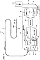
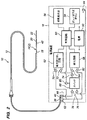
全体として図1及び図2を参照し、本発明の一実施形態に従って構成された医療システム10について説明する。医療システム10は、血管及び神経血管適応に用いられ、特に、動脈瘤、例えば脳動脈瘤の治療に用いられる。医療システム10は、血管閉塞器具、例えば螺旋コイルを動脈瘤内に配備する電解分離手段を利用する。変形例として、医療システム10は、血管閉塞器具以外の埋込型器具を配備するよう利用されても良い。例えば、変形例として、医療システム10は、ステント及び大静脈フィルタを配備するために使用されても良く、これらについては、米国特許第6,468,266号明細書に詳細に説明されている。
A
この目的のため、医療システム10は、主要構成要素として、血管構造内の標的部位に接近するために患者の体内に静脈内的に導入可能な運搬用カテーテル12、運搬用カテーテル12内に摺動可能に設けることができるインプラント組立体14、及び電解分離プロセスを実施するよう電気エネルギをインプラント組立体14に供給することができる電源装置(又は電力供給装置)16を有する。
For this purpose, the
運搬用カテーテル12は、適当なポリマー材料で構成され、オプションとして、強度をもたらし又はねじれ傾向をなくすようコイル又は編組体で補強された細長い柔軟性の管状部材13を有する。運搬用カテーテル12は、インプラント組立体14を選択的に通すことができる内腔(図示せず)を更に有する。運搬用カテーテル12は、管状部材13の遠位端部に設けられていて、血管閉塞インプラント22に対する運搬用カテーテル12の視覚化を可能にする1対の放射線不透過性マーカ15を更に有する。運搬用カテーテル12は、管状部材13の近位端部に設けられていて、インプラント組立体14の導入のため及び色素又は処理材料のオプション的導入のための近位取り付け具17を更に有する。
The
インプラント組立体14は、プッシャ部材18、電解作用で切り離し可能な継手20、及び継手20を電解作用で切り離すと、プッシャ部材18の遠位端部から分離する血管閉塞器具22を有している。プッシャ部材18は、代表的には、プッシャ部材18に所要の引張強度及び柱強度を与える導電性コア(図示せず)、電気絶縁覆い(図示せず)、及びプッシャ部材18の遠位端部の可撓性を増大させる可撓性コイル(図示されている)を有する。
The
重要なこととして、電源装置16は、種々の形式の埋込み可能な組立体又はインプラント組立体14に使用可能に構成されており、かかるインプラント組立体の中には、単極電解作用手段を用いて血管閉塞器具22を切り離し可能な継手20のところでプッシャ部材18から分離させる単極インプラント組立体14(1)(図1に示されている)の形態を取ることができるものがあり、また、埋込み可能組立体の中には、双極電解作用手段を用いて血管閉塞器具22を切り離し可能な継手20のところでプッシャ部材18から分離させる双極インプラント組立体14(2)(図2に示されている)の形態を取ることができるものがある。
Significantly, the
単極インプラント組立体14(1)は、プッシャ部材18の遠位端部に設けられた単一の端子28(電源装置16と結合状態で示されている)を有する。単一の端子28は、下に位置するコアワイヤを単に露出させることによりプッシャ部材18の近位端部に形成されるのが良い。単一の端子28は、切り離し可能継手20に電気的に結合されている正の端子としての役目を果たす。この場合、システム10は、別個の戻り電極組立体30を有し、この戻り電極組立体は、ケーブル32、ケーブル32の近位端部に設けられた負の端子34、及びケーブル32の遠位端部に設けられた接地パッチ電極又は接地針電極の形態をした外部戻り電極36を有し、この外部戻り電極は、インプラント組立体14(1)から見て遠くに位置する患者の組織に接触可能である。かくして、プッシャ部材18の遠位端部のところの切り離し可能継手20と切り離し可能継手20から見て遠くに位置する戻り電極32との間に単極患者用回路を形成することができる。単極患者用回路を向上させるためにオプションとして中間戻り電極(図示せず)をプッシャ部材18の遠位端部により支持するのが良い。
Monopolar implant assembly 14 (1) has a single terminal 28 (shown coupled to power supply 16) provided at the distal end of
これとは対照的に、双極インプラント組立体14(2)は、プッシャ部材18の近位端部に設けられた正及び負の端子38,40(電源装置16と結合状態で示されている)、及び切り離し可能継手20に隣接してプッシャ部材18の遠位端部によって支持された戻り(接地)電極42を有している。正端子32は、切り離し可能継手20に電気的に結合され、負端子34は、戻り電極に電気的に結合されている。かくして、切り離し可能継手20とプッシャ部材18の遠位端部のところの戻り電極との間に双極患者用回路を形成することができる。
In contrast, bipolar implant assembly 14 (2) has positive and
単極構成又は双極構成のいずれにおいても、切り離し可能継手20は、アノードとしての役目を果たし、戻り電極又は接地電極は、カソードとしての役目を果たす。単極構成と双極構成の両方において、正端子28,38は、代表的には、プッシャ部材18内で延びてプッシャ部材18に必要な引張強度及び柱状強度を提供するステンレス鋼(又は他の導電性)コアワイヤ(図示せず)を介して、切り離し可能継手20に電気的に結合される。しかしながら、単極構成では、プッシャ部材18の近位端部全体は、代表的には、内在するコアワイヤを露出させるため、絶縁体が施されておらず、この内在するコアワイヤは、正端子28としての役目を果たす。単極及び双極インプラント組立体の種々の例示の構成に関するそれ以上の詳細は、米国特許出願第60/939,032号明細書に開示されている。
In either a monopolar configuration or a bipolar configuration, the detachable joint 20 serves as an anode and the return or ground electrode serves as a cathode. In both unipolar and bipolar configurations, the
電源装置16は、単極インプラント組立体14(1)の切り離し可能継手20と外部接地電極36との間で電気エネルギを運び、それにより継手20を電解作用で切り離して血管閉塞器具22をプッシャ部材18から分離させる単極エネルギ送り出しモードか、切り離し可能継手20と双極インプラント組立体14(2)の戻り電極42との間で電気エネルギを運び、それにより継手20を電解作用で切り離して血管閉塞器具22をプッシャ部材18から分離させる双極エネルギ送り出しモードかのいずれかで選択的に動作可能であるように構成されている。インプラント組立体14のいずれかに送られる電気エネルギは、継手20とその周りの体液との間に電気分解を引き起こす任意の波形を有するのがよいが、好ましくは、直流電流(DC)電気エネルギの形態を取る。
The
使用されるようになったインプラント組立体の形式と一致する適正な電流送り出しモード(双極か単極かのいずれか)に電源装置16をセットするために、電源装置16は、現時点において電源装置16に結合されているインプラント組立体14の電気エネルギ送り出し形式を検出し、次に、検出されたエネルギ送り出し形式に一致したモードで電気エネルギをインプラント組立体14に送り出すよう構成されている。
In order to set the
電源装置16は、電気信号をインプラント組立体14に送り、送った信号に応答して電気パラメータを測定することによりインプラント組立体のエネルギ送り出し形式を検出する。図示の実施形態では、送り出される信号は、交流(AC)信号であり、測定される電気パラメータは、インピーダンスであるが、送り出される信号が例えば一定直流電流(DC)信号であっても良く、測定される電気パラメータは、例えば、電圧の大きさ又は電流の大きさであっても良い。
The
図示の実施形態では、電源装置16は、電気信号をプッシャ部材18の近位端部のところの2つの箇所相互間に伝送し、これら2つの箇所相互間のインピーダンスを測定してインプラント組立体14のエネルギ送り出し形式を検出するよう構成されている。特に、単極インプラント組立体14(1)が電源装置16に結合される場合、電気信号が伝送される2つの箇所は、インプラント組立体14(1)の正端子28の長さ(即ち、露出されたコアワイヤに沿う箇所相互間の長さ)で繋がり、それにより比較的短い電気経路による短絡が生じる。その結果、この場合に2つの箇所相互間で測定されるインピーダンスの測定値は、ほぼゼロであり、これは2つの箇所相互間の短絡を意味する。
In the illustrated embodiment, the
これとは対照的に、双極インプラント組立体14(2)が電源装置16に結合される場合、電気信号が伝送される2つの箇所は、インプラント組立体14(2)の正端子38と負端子40である。その結果、2つの箇所相互間で測定されるインピーダンスは、有限である。というのは、正端子38と負端子40との間の電気経路は、プッシャ部材18の全長に沿い、プッシャ部材18の遠位端部のところに設けられた切り離し可能継手20とプッシャ部材18の遠位端部のところに設けられた戻り電極42との間で血液を通り、そしてプッシャ部材18の全長に沿って戻って延び、それにより2つの箇所相互間に抵抗負荷が存在していることを意味するからである。
In contrast, when the bipolar implant assembly 14 (2) is coupled to the
かくして、インピーダンス測定値に基づいて、電源装置16は、インプラント組立体の形式を識別することができ、特に、電源装置16に現在結合されているインプラント組立体14が電流の双極送り出しを必要としているか単極送り出しを必要としているかを識別することができる。すなわち、電源装置16は、現在結合されているインプラント組立体14を、測定インピーダンスがほぼゼロである場合に単極のものとして検出し、測定インピーダンスがしきい値よりも小さい有限値である場合、双極のものとして検出する。
Thus, based on the impedance measurement, the
特に、単極であるにせよ双極であるにせよいずれにせよ、患者用回路は、インプラント組立体14の電流送り出しモードの検出エラーが生じた場合(即ち、双極インプラント組立体が単極インプラント組立体として検出され、或いは、単極インプラント組立体が双極インプラント組立体として検出された場合)、電源装置16が結合状態のインプラント組立体14と適合していない場合、インプラント組立体14又は接地電極組立体30が電源装置16に正しく結合されていない場合、或いは、インプラント組立体14又は接地電極組立体30内に電気接続の破断が存在する場合、正しく機能しない。
In particular, whether monopolar or bipolar, the patient circuit may detect that the current delivery mode detection error of the
かくして、図示の実施形態では、電源装置16は又、単極インプラント組立体14(1)が当初検出された場合、電気信号を正端子28と負端子34との間で伝送し、或いは双極インプラント組立体14が当初検出された場合、電気信号を正端子38と負端子40との間で伝送し、次にインピーダンスを測定することにより患者用回路の適正な機能状態をチェックするよう構成されている。患者用回路が正しく機能している場合、測定インピーダンスは、有限であり(即ち、正端子28と負端子34との間、又は正端子38と負端子40との間に抵抗負荷があることを指示する)、回路が不適切に機能している場合、測定インピーダンスは、無限である(即ち、正端子28と負端子34との間、又は正端子38と負端子40との間に開回路が存在していることを指示する)。
Thus, in the illustrated embodiment, the
かくして、測定インピーダンスがプッシャ部材18の近位端部上の2つの箇所相互間の開回路を指示している場合、電源装置16は、電気接続不良をユーザに指示するよう構成されている。単極インプラント組立体が検出された場合、電源装置16は、別の電気信号(例えば、AC信号)をプッシャ部材18の近位端部と接地電極36との間に伝送し、この別の電気信号の伝送に応答して別の電気パラメータ(特に、インピーダンス)を測定し、別の測定されたインピーダンスがプッシャ部材18の近位端部と接地電極36との間の開回路を指示している場合、電気接続不良を指示するよう構成されている。電源装置16は、オプションとして、プッシャ部材18の近位端部上の2つの箇所相互間で測定されたインピーダンス、又はプッシャ部材の近位端部と接地電極36との間で測定されたインピーダンスが開回路を指示している場合、接続状態をチェックするようユーザに知らせるチェックモードを開始させるよう構成されているのが良い。
Thus, when the measured impedance indicates an open circuit between two locations on the proximal end of the
電源装置16は、測定インピーダンスがしきい値よりも大きい場合、この測定インピーダンスが開回路を指示していることを前提にすることができる。特に、プッシャ部材18の遠位端部のところの切り離し可能継手20から遠くに位置する接地電極36まで延びる組織を横切って正しく機能している単極患者用回路のインピーダンスは、プッシャ部材18の遠位端部のところの切り離し可能継手20と戻り電極42との間に位置する組織しか横切っていない状態で正しく機能している双極患者用回路のインピーダンスよりも大きいであろう。かくして、電源装置16は、互いに異なるしきい値に基づいて、結合状態のインプラント組立体14への電気エネルギの供給を阻止することができる。例えば、プッシャ部材18の近位端部上の2つの箇所相互間の測定インピーダンスがしきい値よりも大きい場合(例えば、500オームよりも大きい場合)、又はプッシャ部材18の近位端部と接地電極36との間の測定インピーダンスがしきい値よりも大きい場合(例えば、200オームよりも大きい場合)、電源装置16は、インプラント組立体14への電気エネルギの供給を阻止するよう構成されるのが良い。
If the measured impedance is greater than the threshold, the
変形実施形態では、電源装置16は、接地電極36が電源装置16に結合されているかどうかを検出することにより、インプラント組立体14のエネルギ送り出し形態を検出するよう構成される。すなわち、接地電極36が電源装置16に結合されているかいないかは、電源装置16に結合されているインプラント組立体14のエネルギ送り出し形式を表わす。かくして、この場合、電源装置16は、接地電極36が電源装置16に結合されている場合、結合状態のインプラント組立体14のエネルギ送り出し形式が単極形式であることを指示し、接地電極36が電源装置16に結合されていない場合、結合状態のインプラント組立体14のエネルギ送り出し形式が双極形式であることを指示するよう構成されている。当然のことながら、結合状態のインプラント組立体14のエネルギ送り出し形式を検出するこの方法論は、ユーザの意思への依存度が高く、かくして、ユーザが双極インプラント組立体14(2)及び接地電極36を電源装置16に結合し、又は接地電極36を電源装置16に結合しないで単極インプラント組立体14(1)を結合することにより、誤りを犯した場合には上述の検出方法論ほど適切であるとは言えないことがある。
In an alternative embodiment, the
電源装置16の機能を説明したが、次に、そのコンポーネントについて説明する。電源装置16は、必要な電圧レベルで電力を電源装置16のコンポーネントに供給するよう構成された電源50と、電源装置16に結合されたインプラント組立体14の血管閉塞器具22を電解作用で分離させるのに必要な電気エネルギを送り出すよう構成された電力送り出し回路52とを有している。
Having described the functions of the
電源50は、従来型コンポーネント、例えば1つ又は2つ以上の電池(例えば、標準の9Vアルカリ電池又はAAA電池)、及び1つ又は複数の電池の出力により提供される電圧を電源装置16のコンポーネントによって利用可能な種々の電圧に変換する1つ又は2つ以上の電圧調整器(図示せず)を有するのが良い。
The
電力送り出し回路52は、必要なだけの高い電圧を印加して所要の電流を維持する定電流源の形態を取ることができる出力駆動回路(図示せず)、出力駆動回路をターンオンする電流イネーブル回路(図示せず)、出力駆動回路により出力された電流の大きさを調節する電流調節回路(図示せず)、及び、パワーアップ診断時、血管閉塞器具22を分離させた後、又は処置中に故障が生じた場合、インプラント組立体14を出力駆動回路から切り離すよう付勢できる患者隔離継電器(図示せず)を有するのが良い。図示の実施形態では、電力送り出し回路52により出力される電流は、一定直流電流(DC)波形である。ただし、電気分解を引き起こす他の波形を用いても良い。電力送り出し回路52から送られる電気エネルギは、好ましくは、0.1〜10ミリアンペアである。変形例として、電圧源が用いられる場合、電力送り出し回路52から送られる電気エネルギは、好ましくは、0.1〜10ボルトである。
The
電源装置16は、電源装置16を交互に作動させたり作動を停止したりするよう構成された電力オン/オフ式アクチュエータ54、及び電源装置16の状態及び電解分離プロセスを指示する状態表示器56を更に有する。オン/オフ式アクチュエータ54は、ユーザが電力送り出し回路52を作動させたり作動を停止したりするよう交互に押すことができる従来型押しボタントグルスイッチの形態をしているのが良い。すなわち、オン/オフ式アクチュエータ54を最初に作動させると、電力送り出し回路52は、電気エネルギを結合状態のインプラント組立体14に送り出し、オン/オフ式アクチュエータ54を次に作動させると、電力送り出し回路52は、結合状態のインプラント組立体14への電気エネルギの送り出しを停止する。状態表示器56は、例えば電池電力低下(ローバッテリ)、電力送り出し状態、血管閉塞器具22の分離、及び患者用回路内の接続の間違いのような状態を指示する任意の可視及び(又は)可聴表示器の形態を取ることができる。
The
電源装置16は、血管閉塞器具22とプッシャ部材18との間の分離イベントを表わす電気パラメータを検出するよう構成された検出回路58を更に有している。これら機能を実行する際、検出回路58は、電力送り出し回路52によって生じたDC電流と関連してAC信号を重畳し又は違ったやり方で発生させる交流電流(AC)信号発生器(図示せず)、及びAC信号の大きさを測定しDC信号を出力するピーク検出器及びAC‐DC整流器(図示せず)を有するのが良い。検出回路58は、電力送り出し回路52によって出力されたDC信号の大きさを測定するDCモニタを更に有するのが良い。
The
電源装置16は、電源装置16の重要な機能をモニタしたり制御したりするよう構成された制御回路60を更に有する。制御回路60は、例えばユーザによるオン/オフ式アクチュエータ54の作動に応答して電力送り出し回路の電流イネーブル回路を制御する機能、種々の条件下において電力送り出し回路の電流調節回路及び患者隔離継電器を制御する機能、検出回路58からのフィードバックに基づいて血管閉塞器具22の分離を判定する機能、状態表示器を管理する機能、自己診断を実行する機能等を実行するマイクロコントローラを有するのが良い。制御回路60は、ファームウェア、ハードウェア、ソフトウェア又はこれらの組み合わせの状態で具体化できる。
The
電源装置16により実行される従来機能に関し、上述のコンポーネントの機能上の細部の大部分は、米国特許第5,669,905号明細書及び同第6,397,850号明細書に記載されている。しかしながら、上述したように、電源装置16は、血管閉塞器具22をプッシャ部材18から分離させるよう単極モードか双極モードかのいずれにおいても電気エネルギをインプラント組立体14に送り出す能力を備えている。
With respect to conventional functions performed by the
この目的のため、電源装置16は、単極インプラント組立体14と双極インプラント組立体14の両方に対応することができる電気接点を備えている。特に、電源装置16は、単極インプラント組立体14(1)(図1)の正端子28、又は双極インプラント組立体14(2)(図2)の正端子38に直接接触するよう構成された正の電気接点62と、接地電極組立体30(図1)の負端子34に直接接触するよう構成された第1の負の電気接点64と、双極インプラント組立体14(2)(図2)の負端子40に電気的に結合可能に構成された第2の負の電気接点66とを有している。本明細書の目的上、端子又は接点に関して「正」及び「負」という用語は、相対的なものであり、正端子又は正接点が負端子又は負接点よりも高い電圧印加状態にあることを意味しているに過ぎない。
For this purpose, the
電源装置16と双極インプラント組立体14(2)との適合性を保証するため、正電気接点62及び第2の負電気接点66は、好ましくは、これらがそれぞれ、電源装置16に結合された場合のインプラント組立体14(2)の正端子38及び負端子40に接触するよう配置されると共に互いに間隔を置いて設けられている。単極インプラント組立体14(1)のプッシャ部材18の近位端部全体は、正端子28としての役目を果たすので、電源装置16の正電気接点62は、当然のことながら、インプラント組立体14(2)のプッシャ部材18を電源装置16に結合する場合、正電気接点62の位置にそれほど気にかけないで、正端子28と接触関係をなす。
In order to ensure compatibility between the
制御回路60は、電力送り出し回路52に選択的に指図して、これを、電気エネルギが正電気接点62と第1の負電気接点64との間で送られる単極送り出しモードか、電気エネルギが正電気接点62と第2の負電気接点66との間で送られる双極送り出しモードかのいずれかで動作させるよう構成されている。
The
この目的のため、電源装置16は、正電気接点62と第1の負電気接点64との間、又は正電気接点62と第2の負電気接点66との間で電力送り出し回路52を選択的に結合できるようにするスイッチ68を更に有する。特に、電力送り出し回路52は、正電気接点62に結合された正端子70、及びスイッチ68により第1及び第2の負接点64,66に結合された負の端子72を有している。
For this purpose, the
すなわち、スイッチ68は、電力送り出し回路52の負端子72に結合された入力端子74、第1の負電気接点64に結合された第1の出力端子76、及び第2の負電気接点66に結合された第2の出力端子78を有している。スイッチ68は、制御回路60が結合された制御端子80を更に有している。かくして、制御回路60は、スイッチ68の入力端子74(及びかくして電力送り出し回路52の負端子72)をスイッチ68の第1の出力端子76(及びかくして第1の負電気接点64)に結合し、それにより電力送り出し回路52を単極モードにするか、スイッチ68の第2の出力端子78(及びかくして第2の負電気接点66)に結合し、それにより電力送り出し回路52を双極モードにするかのいずれかを選択的に行うよう制御信号をスイッチ68に送ることができる。
That is,
したがって、制御回路60の制御下で(且つオン/オフ式アクチュエータ54の作動に応答して)、電力送り出し回路52は、電気信号を正電気接点62と第1の負電気接点64との間(かくして、単極インプラント組立体14の正端子28と接地電極組立体30の負端子34との間)に送り出して血管閉塞器具22をプッシャ部材18から分離させることができ、或いは、電力送り出し回路52は、電気エネルギを正電気接点62と第2の負電気接点66との間(かくして、双極インプラント組立体14(2)の正端子38と負端子40との間)に送り出して血管閉塞器具22をプッシャ部材18から分離させることができる。
Thus, under control of the control circuit 60 (and in response to actuation of the on / off actuator 54), the
図示の実施形態では、制御回路60は、インプラント組立体14のエネルギ送り出し形式を判定するよう構成され、制御回路60は、判定されたエネルギ送り出し形式が単極形式である場合、電力送り出し回路52に指図して電気エネルギを正電気接点62(かくして、単極インプラント組立体14(1)の正電気端子28)と第1の負電気接点64(かくして、接地電極組立体30の負電気端子34)との間に送り出し、検出されたエネルギ送り出し形式が双極形式である場合、電力送り出し回路52に指図して電気エネルギを正電気接点62と第2の負電気接点66との間(かくして、双極インプラント組立体14(2)の正電気端子38と負電気端子40との間)に送り出すよう構成されている。
In the illustrated embodiment, the
インプラント組立体14のエネルギ送り出しモードを判定するため、制御回路60は、検出回路58に指図して電気信号(例えば、AC信号)を正電気接点62に送り、送った電気信号に応答して電気パラメータを測定するよう構成されている。特に、電気信号は、正電気接点62と負電気接点66との間(及びかくしてプッシャ部材18の近位端部を横切る2つの箇所相互間)に送られ、測定された電気パラメータは、電気接点62,66相互間のインピーダンスを表わす。制御回路60は、正電気接点62と第2の負電気接点66との間のインピーダンスがほぼゼロであり、これが電気接点62,66相互間の短絡を指示している場合、インプラント組立体14のエネルギ送り出し形式が単極のものであると判定し、正電気接点62と第2の負電気接点66との間のインピーダンスが有限であり、これが電気接点62,66相互間の抵抗負荷を指示している場合、インプラント組立体14のエネルギ送り出し形式が双極のものであると判定するよう構成されている。
In order to determine the energy delivery mode of the
制御回路60は、更に、患者用回路が正しく機能しているかどうかを判定し、患者用回路が正しく機能していなければ、電気接続不良を指示するよう状態表示器56のうちの1つ又は2つ以上に指図するよう構成されている。特に、正電気接点62と第2の負電気接点66との間のインピーダンスが開回路を指示している場合(即ち、インピーダンス値がしきい値、例えば500オームよりも大きい場合)、制御回路60は、双極患者用回路内に電気接続不良があることをユーザに知らせるよう状態表示器56のうちの1つ又は2つ以上に指図するよう構成されている。単極エネルギ送り出し形式が検出された場合、単極患者用回路の機能実行状態をチェックする必要がある。この場合、制御回路60は、別の電気信号(例えば、AC信号)を正電気接点62(かくして、単極インプラント組立体14(1)の正電気端子38)と第1の負電気接点64(かくして、接地電極組立体30の負電気端子34)との間に伝送するよう検出回路58に指図し、正電気接点62と第1の負電気接点64との間のインピーダンスを表わす別の電気パラメータを測定するよう構成されている。正電気接点62と第1の負電気接点64との間のインピーダンスが開回路を指示している場合(即ち、インピーダンス値が、しきい値、例えば2000オームよりも大きい場合)、制御回路60は、単極患者用回路内に電気接続不良があることをユーザに知らせるよう状態表示器56のうちの1つ又は2つ以上に指図するよう構成されている。
The
現時点において電源装置16に結合されているインプラント組立体14のプッシャ部材18の近位端部にわたるインピーダンスを測定することにより、電源装置16がインプラント組立体14の形式を検出することができるようにすると共に、単極患者用回路と双極患者用回路の両方の機能実行状態をチェックするため、検出回路58は、電力送り出し回路52と同様、正電気接点62と第1の負電気接点64との間、又は正電気接点62と第2の負電気接点66との間にスイッチ68を介して選択的に結合される。
Measuring the impedance across the proximal end of the
特に、検出回路58は、正電気接点62に結合された正端子82と、スイッチ68を介して第1及び第2の負接点64,66に結合された負端子84とを有している。すなわち、スイッチ68の入力端子74は、検出回路58の負端子84に結合されている。かくして、制御回路60は、制御信号をスイッチ68に送ってスイッチ68の入力端子74(かくして、検出回路58の負端子84)をスイッチ68の第1の出力端子76(かくして、第1の負電気接点64)か、スイッチ68の第2の出力端子78(かくして、第2の負電気接点66)かのいずれかに選択的に結合することができる。
In particular, the
このように、検出回路58は、伝送した電気信号に応答して、正電気接点62と第1の負電気接点64との間のインピーダンス(従って、単極モードにおける患者用回路の機能実施状態をチェックすることができる)、又は正電気接点62と第2の負電気接点66との間のインピーダンス(従って、インプラント組立体の形式を検出することができ、又は双極モードにおける患者用回路の機能実施状態をチェックすることができる)を表わす電気パラメータを測定するよう構成されている。
In this way, the
接地電極36が電源装置16に結合されているかどうかに基づいて、電源装置16が結合状態のインプラント組立体14のエネルギ送り出し形式を判定する変形実施形態では、制御回路60は、検出回路58に指図して第1の負電気接点64への接地電極36の結合を検出させるよう構成されている。制御回路60は、検出回路58に指図して接地電極36と第1の負電気接点64との間の結合を検出させることによりインプラント組立体14のエネルギ送り出し形式を判定するよう構成されている。第1の負電気接点64への接地電極36の結合は、適当な手段を用いて、例えば、電源装置16に結合された場合に、接地電極組立体30の端子34が接触する2つの接点(図示せず)相互間のインピーダンスを測定して検出でき、短絡は、接地電極36と第1の負電気接点との間のかかる結合を指示する。第1の負電気接点64への接地電極36の結合が検出された場合、制御回路60は、エネルギ送り出し形式が単極形式であると判定するよう構成され、第1の負電気接点64への接地電極36の結合が検出されなかった場合、制御回路60は、エネルギ送り出し形式が双極送り出しモードであると判定するよう構成されている。
In an alternative embodiment in which the
次に、図3〜図6を参照して、電源装置16の物理的コンポーネントについて説明する。電源装置16は、電源装置16のコンポーネントを包囲したキャビティ88を備えている携帯可能な手持ち形ハウジング86を有する。図示の実施形態では、ハウジング86は、適当な医用硬質材料、例えばポリカーボネートで構成されており、手の中に容易に保持できるペンによく似た円筒形の形をしている。
Next, physical components of the
電源装置16は、電子コンポーネントを支持するよう構成されたプリント回路板90を更に有し、かかる電子コンポーネントとしては、電力オン/オフ式アクチュエータ54、正電気接点62、第1及び第2の負電気接点64,66、及び状態表示器56を含んでいる。電源50(電池を除く)、電力送り出し回路52、検出回路58、制御回路60及びスイッチ68は、図3〜図6には示されていないが、これらも又、プリント回路板90によって支持されている。電源装置16は、電池92(図1及び図2に示されている電源50の一部として)を更に有し、この電池の正端子94は、プリント回路板90に取り付けられた電力端子96と直接的な電気的接触状態にあり、電池の負端子(図示せず)は、ケーブル(図示せず)を介してプリント回路板90の負端子(図示せず)に間接的に結合されている。電池92は、任意適当な薄形電池、例えばAAA電池の形態を取ることができ、多数回の分離を実施するのに十分な電力を提供することができる。電源装置16の費用は、1回の臨床手技後にその処分を経済的に可能にするのに足るほど低いものであることができる。
The
図示の実施形態では、電気接点62〜66は、プリント回路板90に設けられた貫通穴98(図4及び図5に示されている)内に固定的に設けられ、これら電気接点は、プリント回路板90によって支持された電力送り出し回路52に電気的に結合されている。電力オン/オフ式アクチュエータ54は、ハウジング86の外部に取り付けられたボタン100及びプリント回路板90に直接取り付けられたスイッチ102を有している。ユーザがボタン100を押すことにより、スイッチ102は、図1及び図2を参照して上述したような仕方で正電気接点62と第1の負電気接点64又は第2の負電気接点66との間での電力送り出し回路52からの電気エネルギの送り出し又はその停止を行うよう操作される。状態表示器56は、発光ダイオード(LED)の形態をしており、これら発光ダイオードは、上述したように、ユーザに、例えば電池電力低下、電力送り出し状態、患者用回路内の接続間違いのような状態を指示することができる。状態表示器56は、ハウジング86に形成された孔104(図4及び図5に示されている)を介して露出されている。
In the illustrated embodiment, the electrical contacts 62-66 are fixedly provided in through holes 98 (shown in FIGS. 4 and 5) provided in the printed
電源装置16は、接地電極組立体30の負端子34を第1の負電気接点64に接触させるよう接地ケーブル32(図3〜図6には示されていない)の近位端部を受け入れるよう構成された接地ポート106を有している。電源装置16は、プッシャ部材18の近位端部を受け入れるよう構成されたポート108と、単極インプラント組立体14(1)の正端子28を押圧してこれをプリント回路板90に取り付けられている正電気接点62及び第2の負電気接点66にしっかりと電気的に接触させるか、双極インプラント組立体14(2)の正端子38及び負端子40をそれぞれ押圧してこれらをプリント回路板90に取り付けられている正電気接点62及び第2の負電気接点66にしっかりと電気的に接触させるよう構成された電気絶縁的な柔軟性又は適合性の部材110と、を有している。
The
柔軟性部材110は、電気絶縁弾性材料で構成されるのが良い。図示の実施形態では、柔軟性部材110は、プリント回路板90の下面の真下にこれと接触状態に設けられた柔軟性又は適合性圧力パッドの形態をしており、従って、プッシャ部材18の近位端部を柔軟性パッド110の上面とプリント回路板90の下面との間で前進させるようになっている。正電気接点62及び第2の負電気接点66は、ポート108のすぐ近位側に配置されていて、プッシャ部材18の近位端部が近位側方向にポート108を出ると、プッシャ部材18に設けられている端子が正電気接点62及び第2の負電気接点66に接触するようになる。
The
ポート108は、プッシャ部材18の近位端部を案内してこれを正電気接点62及び第2の負電気接点66に整列させるように形作られている。特に、ポート108は、大径遠位部分114及び小径近位部分116を備えたファンネル112と、ファンネル112の小径近位部分116と連通状態にある円筒形管118とを有している。かくして、プッシャ部材18の近位端部をポート108内に導入すると、この近位端部は、円筒形管118内に入り込んで行き、次に、この円筒形管は、プッシャ部材18の近位端部を案内して、これを電気接点62,66に整列させる。図示の実施形態では、円筒形管118は、図6に最も良く示されているように柔軟性パッド110内に埋め込まれており、従って、円筒形管118は、プリント回路板90の底面と柔軟性パッド110との間のしっかりとした接触状態を妨げないようになっている。
理解できるように、ポート108と柔軟性パッド110との間の相互作用により、単にプッシャ部材18をポート108内に挿入するだけで、インプラント組立体14と電源装置16との間の結合が容易になる。特に、この構成により、種々の形式及びサイズのプッシャ部材18を電源装置16に結合することができる。オプションとしての実施形態では、電源装置16は、電気接点62,66を外部環境から封止するようポート108内に設けられたゲル材料(図示せず)を更に有し、それにより、液体及び(又は)固体汚染物が分離信頼性に悪影響を及ぼす恐れが減少する。
As can be appreciated, the interaction between the
医療システム10の機能及び構造を説明したが、次に、図7及び図8を参照して医療手技を実施する際、特に血管閉塞器具22を患者の動脈瘤150内に埋込む際のその使用方法について説明する。血管閉塞器具を患者の体内に埋込むプロセスは、代表的には、局所麻酔を行ってX線透視制御下で実施される。
Having described the function and structure of the
図7を参照すると、運搬用カテーテル12が入口箇所、例えば鼠径部を経て患者の体内に導入され、カテーテル12の先端部が動脈瘤150の頸部154内に、又はこれに隣接して位置した状態で血管152内に位置決めされている。次に、インプラント組立体14を運搬用カテーテル12内に挿入してこれを前進させ、ついには、血管閉塞器具22が動脈瘤150内に位置するようにする。次に、インプラント組立体14を電源装置16に結合する。インプラント組立体14が単極の場合、接地電極組立体30を図1に示すように電源装置16に結合し、インプラント組立体14が双極である場合、図2に示されているように、接地電極組立体30を電源装置16に結合しない。接地電極36がパッチ形電極の形態をしている場合、この電極を患者の皮膚に、例えば、肩の上に付けるのが良い。接地電極36が針電極の形態をしている場合、この電極を患者の体内に、例えば鼠径部内に経皮的に挿入するのが良い。
Referring to FIG. 7, the
図8を参照すると、電気エネルギがオン/オフ電力アクチュエータ54の作動により電源装置16からインプラント組立体14に送られ、プッシャ部材18の遠位端部のところの接合部20を切り離し、それにより血管閉塞器具22をプッシャ部材18から分離させる。血管閉塞器具22の閉塞により、動脈瘤150内に凝血塊156が形成され、それにより、動脈瘤150が破裂する恐れがなくなる。
Referring to FIG. 8, electrical energy is delivered from the
単極インプラント組立体14(1)の場合、電気エネルギを切り離し可能継手20と接地電極36との間に送って血管閉塞器具22をプッシャ部材18から電解作用で分離させる。双極インプラント組立体14(2)の場合、電気エネルギを切り離し可能継手20と戻り電極42との間に送って血管閉塞器具22をプッシャ部材18から電解作用で分離させる。血管閉塞器具22を分離させた後、プッシャ部材18を運搬用カテーテル12から取り出す。追加の血管閉塞器具を運搬用カテーテル12により導入し、この血管閉塞器具を動脈瘤150内に電解作用で分離させることにより追加の血管閉塞器具を動脈瘤150内に埋込むことができる。
In the case of the monopolar implant assembly 14 (1), electrical energy is sent between the separable joint 20 and the
重要なこととして、オン/オフ電力アクチュエータ54を作動させる前、又はオン/オフ電力アクチュエータ54の作動直後に、インプラント組立体14のエネルギ送り出し形式を自動的に検出し、検出したエネルギ送り出し形式に対応したモードで電気エネルギを電源装置からインプラント組立体14に送り、それにより、継手20を電解作用で切り離し、埋込型器具22をプッシャ部材18から分離させる。
Importantly, the energy delivery type of the
特に、図9を参照すると、電気信号をプッシャ部材18の近位端部上の2つの箇所相互間に伝送し(ステップ160)、伝送された電気信号に応答して電気パラメータを測定する(ステップ162)。測定された電気信号が2つの箇所相互間の短絡を指示している場合(ステップ164)、エネルギ送り出し形式を単極形式として検出する(ステップ166)。測定された電気信号が2つの箇所相互間の抵抗負荷を指示している場合(ステップ168)、エネルギ送り出し形式を双極形式として検出し(ステップ170)、電気エネルギを双極モードでインプラント組立体14に送って動脈瘤150内の血管閉塞器具22を電解作用で分離させる(ステップ172)。
In particular, referring to FIG. 9, an electrical signal is transmitted between two locations on the proximal end of pusher member 18 (step 160), and electrical parameters are measured in response to the transmitted electrical signal (step 160). 162). If the measured electrical signal indicates a short circuit between the two locations (step 164), the energy delivery format is detected as a unipolar format (step 166). If the measured electrical signal indicates a resistive load between the two locations (step 168), the energy delivery type is detected as a bipolar type (step 170) and the electrical energy is transmitted to the
エネルギ送り出し形式が単極形式として検出された場合、電気エネルギをすぐにはインプラント組立体14に送り出さない。その代わり、別の電気信号をプッシャ部材18の近位端部と接地電極36との間に伝送し(ステップ174)、この伝送された別の電気信号に応答して別の電気パラメータを測定する(ステップ176)。測定された電気パラメータがプッシャ部材18の近位端部と接地電極36との間の抵抗負荷を指示している場合(ステップ178)、電気エネルギを単極モードでインプラント組立体14に送って動脈瘤150内の血管閉塞器具22を電解作用で分離させる(ステップ180)。
If the energy delivery type is detected as a monopolar type, electrical energy is not delivered immediately to the
ステップ172において送り出された電気信号に応答して測定された電気パラメータが短絡と抵抗負荷のいずれも指示していない場合(即ち、かかる電気パラメータが2つの箇所相互間の開回路を指示している場合)、又はステップ174で伝送された別の電気エネルギに応答して測定された別の電気パラメータが抵抗負荷を指示していない場合(即ち、かかる別の電気パラメータがプッシャ部材18の近位端部と接地電極36との間の開回路を指示している場合)、電気接続不良が伝えられ、その結果、ユーザは、システムの電気接続状態をチェックすることができ(ステップ182)、その後プロセスをステップ160で繰り返し実施することができる。
If the electrical parameter measured in response to the electrical signal delivered in
別の方法では、接地電極36が電源装置16に結合されているかどうかを検出することによってエネルギ送り出し形式を検出する。特に、接地電極と電源装置との間の結合が検出された場合、インプラント組立体14のエネルギ送り出し形式は、単極形式として検出されることになり、この場合、電気エネルギが単極モードでインプラント組立体14に送り出されて動脈瘤150内の血管閉塞器具22を電解作用で分離させる。接地電極と電源装置との間の結合が検出されなかった場合、インプラント組立体14のエネルギ送り出し形式は、双極形式として検出されることになり、この場合、電気エネルギが双極モードでインプラント組立体14に送り出されて動脈瘤150内の血管閉塞器具22を電解作用で分離させる。
In another method, the energy delivery type is detected by detecting whether the
Claims (37)
インプラント組立体を有し、前記インプラント組立体は、近位端部及び遠位端部を備えた細長いプッシャ部材と、前記プッシャ部材の遠位端部に取り付けられた埋込型器具と、前記プッシャ部材に設けられた電解作用で切り離し可能な継手とを有し、前記埋込型器具は、前記継手を切り離すと、前記プッシャ部材から分離し、
前記インプラント組立体に結合された電源装置を有し、前記電源装置は、前記インプラント組立体のエネルギ送り出し形式を検出し、前記検出されたエネルギ送り出し形式に対応したモードで電気エネルギを前記インプラント組立体に送り出し、それにより前記継手を電解作用で切り離すよう構成されている、医療システム。 A medical system,
An implant assembly comprising an elongated pusher member having a proximal end and a distal end; an implantable device attached to the distal end of the pusher member; and the pusher A joint that can be separated by electrolytic action provided on the member, and the implantable device separates from the pusher member when the joint is separated;
A power supply coupled to the implant assembly, wherein the power supply detects an energy delivery type of the implant assembly and delivers electrical energy in a mode corresponding to the detected energy delivery type; A medical system configured to be fed into the body and thereby to disconnect the joint by electrolysis.
外部接地電極に結合可能に構成された第1の負の電気接点と、
プッシャ部材及び電解作用で分離可能な埋込型器具を備えたインプラント組立体に結合可能に構成された正の電気接点及び第2の負の電気接点と、
双極送り出しモードと単極送り出しモードで選択的に動作可能に構成された電力送り出し回路とを有し、電気エネルギは、前記単極送り出しモードの際、前記正の電気接点と前記第1の負の電気接点との間で送られ、電気エネルギは、前記双極送り出しモードの際、前記正の電気接点と前記第2の負の電気接点との間で送られる、電源装置。 A power supply unit,
A first negative electrical contact configured to be coupled to an external ground electrode;
A positive electrical contact and a second negative electrical contact configured to be connectable to an implant assembly comprising a pusher member and an electrolytically separable implantable device;
A power delivery circuit configured to be selectively operable in a bipolar delivery mode and a unipolar delivery mode, wherein electrical energy is communicated with the positive electrical contact and the first negative delivery during the unipolar delivery mode. A power supply apparatus, wherein electrical energy is transmitted between electrical contacts and between the positive electrical contact and the second negative electrical contact during the bipolar delivery mode.
前記スイッチを選択的に動作させて、前記単極送り出しモードの際、前記入力端子を前記第1の出力端子に結合し、前記双極送り出しモードの際、前記入力端子を前記第2の出力端子に結合するよう構成された制御回路と、を更に有する、請求項13記載の電源装置。 An input terminal coupled to a negative terminal of the power delivery circuit; and a first output terminal and a second output terminal coupled to the first negative electrical contact and the second negative electrical contact, respectively. A switch,
The switch is selectively operated to couple the input terminal to the first output terminal during the unipolar delivery mode and to connect the input terminal to the second output terminal during the bipolar delivery mode. The power supply apparatus according to claim 13, further comprising a control circuit configured to be coupled.
電力送り出し回路と、
前記電力送り出し回路に電気的に結合された電気接点と、
前記細長い部材の前記近位端部を受け入れるよう構成されたポートと、
前記細長い部材の前記近位端部が前記ポート内に受け入れられると、前記電気端子を前記電気接点に接触させるよう構成された電気絶縁柔軟性部材と、を有する、電源装置。 A power supply for a medical device having an elongated member and a terminal provided at a proximal end of the elongated member, the power supply comprising:
A power delivery circuit;
An electrical contact electrically coupled to the power delivery circuit;
A port configured to receive the proximal end of the elongate member;
An electrically insulating flexible member configured to bring the electrical terminal into contact with the electrical contact when the proximal end of the elongate member is received in the port.
細長い部材,前記細長い部材の近位端部に設けられた電気端子,及び前記電気端子と電気的連絡関係をなして前記細長い部材の遠位端部に設けられた少なくとも1つの作動要素,を有する医療器具と、
電力送り出し回路,電気接点,前記細長い部材の前記近位端部が配置されるポート,及び前記電気端子を前記電気接点に接触させる電気絶縁柔軟性部材,を有する電源装置と、を有する、医療システム。 A medical system,
An elongate member, an electrical terminal provided at a proximal end of the elongate member, and at least one actuating element provided at a distal end of the elongate member in electrical communication with the electrical terminal. Medical instruments,
A power system having a power delivery circuit, an electrical contact, a port in which the proximal end of the elongate member is disposed, and an electrically insulating flexible member that causes the electrical terminal to contact the electrical contact. .
Applications Claiming Priority (2)
| Application Number | Priority Date | Filing Date | Title |
|---|---|---|---|
| US94983007P | 2007-07-13 | 2007-07-13 | |
| PCT/US2008/068930 WO2009012057A2 (en) | 2007-07-13 | 2008-07-01 | Hybrid and portable power supplies for electrolytically detaching implantable medical devices |
Publications (1)
| Publication Number | Publication Date |
|---|---|
| JP2010533509A true JP2010533509A (en) | 2010-10-28 |
Family
ID=39714022
Family Applications (1)
| Application Number | Title | Priority Date | Filing Date |
|---|---|---|---|
| JP2010516134A Pending JP2010533509A (en) | 2007-07-13 | 2008-07-01 | Hybrid portable power supply device that separates implantable medical devices by electrolysis |
Country Status (7)
| Country | Link |
|---|---|
| US (1) | US20090018653A1 (en) |
| EP (1) | EP2170176A2 (en) |
| JP (1) | JP2010533509A (en) |
| CN (1) | CN101686834A (en) |
| AU (1) | AU2008276344A1 (en) |
| CA (1) | CA2692408A1 (en) |
| WO (1) | WO2009012057A2 (en) |
Cited By (1)
| Publication number | Priority date | Publication date | Assignee | Title |
|---|---|---|---|---|
| JP2017517358A (en) * | 2014-04-11 | 2017-06-29 | マイクロベンション インコーポレイテッド | Implant delivery system |
Families Citing this family (26)
| Publication number | Priority date | Publication date | Assignee | Title |
|---|---|---|---|---|
| US8777979B2 (en) | 2006-04-17 | 2014-07-15 | Covidien Lp | System and method for mechanically positioning intravascular implants |
| JP5230602B2 (en) | 2006-04-17 | 2013-07-10 | タイコ ヘルスケア グループ リミテッド パートナーシップ | System and method for mechanically positioning an endovascular implant |
| JP5216994B2 (en) * | 2007-03-27 | 2013-06-19 | 国立大学法人滋賀医科大学 | Microwave surgical device |
| CN102036619B (en) | 2007-12-21 | 2014-07-23 | 微排放器公司 | A system and method of detecting implant detachment |
| JP5366974B2 (en) * | 2007-12-21 | 2013-12-11 | マイクロベンション インコーポレイテッド | System and method for determining the position of a separation zone of a separable implant |
| CA2722037C (en) * | 2008-04-21 | 2016-03-22 | Nfocus Neuromedical, Inc. | Braid-ball embolic devices and delivery systems |
| CN102186426B (en) * | 2008-10-13 | 2013-05-15 | 斯瑞克公司 | Vaso-occlusive coil delivery system |
| WO2010104955A2 (en) * | 2009-03-13 | 2010-09-16 | Boston Scientific Scimed, Inc. | Electrical contact for occlusive device delivery system |
| US20100256666A1 (en) | 2009-04-06 | 2010-10-07 | Boston Scientific Scimed, Inc. | Delivery wire for occlusive device delivery system |
| US9314250B2 (en) | 2009-04-16 | 2016-04-19 | Stryker Corporation | Electrical contact for occlusive device delivery system |
| WO2010120653A1 (en) * | 2009-04-16 | 2010-10-21 | Boston Scientific Scimed, Inc. | Delivery wire for occlusive device delivery system and method of manufacture |
| WO2010120694A1 (en) * | 2009-04-16 | 2010-10-21 | Boston Scientific Scimed, Inc. | Electrical contact for occlusive device delivery system |
| US9814562B2 (en) | 2009-11-09 | 2017-11-14 | Covidien Lp | Interference-relief type delivery detachment systems |
| WO2011062844A1 (en) * | 2009-11-18 | 2011-05-26 | Boston Scientific Scimed, Inc. | Delivery wire assembly for occlusive device delivery system |
| DE102010044746A1 (en) * | 2010-09-08 | 2012-03-08 | Phenox Gmbh | Implant for influencing the blood flow in arteriovenous malformations |
| US8945171B2 (en) | 2011-09-29 | 2015-02-03 | Covidien Lp | Delivery system for implantable devices |
| US8795313B2 (en) | 2011-09-29 | 2014-08-05 | Covidien Lp | Device detachment systems with indicators |
| CN102715930A (en) * | 2011-10-25 | 2012-10-10 | 北京泰杰伟业科技有限公司 | Electric release controller used for embolism spring ring |
| US9579104B2 (en) | 2011-11-30 | 2017-02-28 | Covidien Lp | Positioning and detaching implants |
| CN105142543B (en) | 2013-03-15 | 2019-06-04 | 柯惠有限合伙公司 | The conveying of Vascular implant and separating mechanism |
| CN109982631B (en) * | 2016-11-14 | 2022-08-09 | 皇家飞利浦有限公司 | Wireless intraluminal devices and associated devices, systems, and methods |
| US10244481B2 (en) * | 2017-04-05 | 2019-03-26 | Biosense Webster (Israel) Ltd. | System and method for switching on wireless tool only when the location frequencies are detected |
| US10483886B2 (en) * | 2017-09-14 | 2019-11-19 | Hamilton Sundstrand Corportion | Modular electric power generating system with multistage axial flux generator |
| CN113749718B (en) * | 2020-06-05 | 2024-01-26 | 微创神通医疗科技(上海)有限公司 | Release device, release system, release method and treatment device |
| CN113749717B (en) * | 2020-06-05 | 2023-09-29 | 微创神通医疗科技(上海)有限公司 | Release device, release system, release method and treatment device |
| DE102022117911A1 (en) | 2022-07-18 | 2024-01-18 | Standard Instruments GmbH Gesellschaft für Medizintechnik, Mess- und Regeltechnik, Steuerungstechnik | Connection cable and detachment device |
Citations (3)
| Publication number | Priority date | Publication date | Assignee | Title |
|---|---|---|---|---|
| JPH0284964A (en) * | 1988-03-18 | 1990-03-26 | Tokai Rika Co Ltd | High frequency power source device for balloon catheter |
| US6113596A (en) * | 1996-12-30 | 2000-09-05 | Enable Medical Corporation | Combination monopolar-bipolar electrosurgical instrument system, instrument and cable |
| US20060036280A1 (en) * | 2004-08-11 | 2006-02-16 | Concentric Medical, Inc. | Systems and methods for severing occlusive elements from a delivery catheter |
Family Cites Families (24)
| Publication number | Priority date | Publication date | Assignee | Title |
|---|---|---|---|---|
| DE2646229A1 (en) * | 1976-10-13 | 1978-04-20 | Erbe Elektromedizin | HIGH FREQUENCY SURGICAL EQUIPMENT |
| US5122136A (en) * | 1990-03-13 | 1992-06-16 | The Regents Of The University Of California | Endovascular electrolytically detachable guidewire tip for the electroformation of thrombus in arteries, veins, aneurysms, vascular malformations and arteriovenous fistulas |
| US5569245A (en) * | 1990-03-13 | 1996-10-29 | The Regents Of The University Of California | Detachable endovascular occlusion device activated by alternating electric current |
| CA2162117C (en) * | 1994-03-03 | 2000-01-25 | Ronald W. Scheldrup | Endovascular embolic device detachment detection method and apparatus |
| US5472442A (en) * | 1994-03-23 | 1995-12-05 | Valleylab Inc. | Moveable switchable electrosurgical handpiece |
| US5505730A (en) * | 1994-06-24 | 1996-04-09 | Stuart D. Edwards | Thin layer ablation apparatus |
| US6241753B1 (en) * | 1995-05-05 | 2001-06-05 | Thermage, Inc. | Method for scar collagen formation and contraction |
| US5755753A (en) * | 1995-05-05 | 1998-05-26 | Thermage, Inc. | Method for controlled contraction of collagen tissue |
| US5980514A (en) * | 1996-07-26 | 1999-11-09 | Target Therapeutics, Inc. | Aneurysm closure device assembly |
| US5984929A (en) * | 1997-08-29 | 1999-11-16 | Target Therapeutics, Inc. | Fast detaching electronically isolated implant |
| US6077260A (en) * | 1998-02-19 | 2000-06-20 | Target Therapeutics, Inc. | Assembly containing an electrolytically severable joint for endovascular embolic devices |
| US6508815B1 (en) * | 1998-05-08 | 2003-01-21 | Novacept | Radio-frequency generator for powering an ablation device |
| US6397850B1 (en) * | 2000-02-09 | 2002-06-04 | Scimed Life Systems Inc | Dual-mode apparatus and method for detection of embolic device detachment |
| US7422586B2 (en) * | 2001-02-28 | 2008-09-09 | Angiodynamics, Inc. | Tissue surface treatment apparatus and method |
| EP1429678B1 (en) * | 2001-09-28 | 2006-03-22 | Rita Medical Systems, Inc. | Impedance controlled tissue ablation apparatus |
| US20050277918A1 (en) * | 2003-03-07 | 2005-12-15 | Baylis Medical Company Inc. | Electrosurgical cannula |
| US6830569B2 (en) * | 2002-11-19 | 2004-12-14 | Conmed Corporation | Electrosurgical generator and method for detecting output power delivery malfunction |
| CA2507649C (en) * | 2003-04-02 | 2011-10-11 | Mehran Bashiri | Detachable and retrievable stent assembly |
| US7094231B1 (en) * | 2004-01-22 | 2006-08-22 | Ellman Alan G | Dual-mode electrosurgical instrument |
| US7766905B2 (en) * | 2004-02-12 | 2010-08-03 | Covidien Ag | Method and system for continuity testing of medical electrodes |
| US20060271097A1 (en) * | 2005-05-31 | 2006-11-30 | Kamal Ramzipoor | Electrolytically detachable implantable devices |
| US20070073334A1 (en) * | 2005-09-29 | 2007-03-29 | Kamal Ramzipoor | Combined electrolytic and mechanical separation background |
| US7942872B2 (en) * | 2006-02-27 | 2011-05-17 | Moshe Ein-Gal | Blended monopolar and bipolar application of RF energy |
| US20080140113A1 (en) * | 2006-12-07 | 2008-06-12 | Cierra, Inc. | Method for sealing a pfo using an energy delivery device |
-
2008
- 2008-07-01 CN CN200880024289A patent/CN101686834A/en active Pending
- 2008-07-01 EP EP20080781246 patent/EP2170176A2/en not_active Withdrawn
- 2008-07-01 WO PCT/US2008/068930 patent/WO2009012057A2/en active Application Filing
- 2008-07-01 CA CA 2692408 patent/CA2692408A1/en not_active Abandoned
- 2008-07-01 AU AU2008276344A patent/AU2008276344A1/en not_active Abandoned
- 2008-07-01 US US12/166,190 patent/US20090018653A1/en not_active Abandoned
- 2008-07-01 JP JP2010516134A patent/JP2010533509A/en active Pending
Patent Citations (3)
| Publication number | Priority date | Publication date | Assignee | Title |
|---|---|---|---|---|
| JPH0284964A (en) * | 1988-03-18 | 1990-03-26 | Tokai Rika Co Ltd | High frequency power source device for balloon catheter |
| US6113596A (en) * | 1996-12-30 | 2000-09-05 | Enable Medical Corporation | Combination monopolar-bipolar electrosurgical instrument system, instrument and cable |
| US20060036280A1 (en) * | 2004-08-11 | 2006-02-16 | Concentric Medical, Inc. | Systems and methods for severing occlusive elements from a delivery catheter |
Cited By (1)
| Publication number | Priority date | Publication date | Assignee | Title |
|---|---|---|---|---|
| JP2017517358A (en) * | 2014-04-11 | 2017-06-29 | マイクロベンション インコーポレイテッド | Implant delivery system |
Also Published As
| Publication number | Publication date |
|---|---|
| AU2008276344A1 (en) | 2009-01-22 |
| US20090018653A1 (en) | 2009-01-15 |
| CN101686834A (en) | 2010-03-31 |
| CA2692408A1 (en) | 2009-01-22 |
| EP2170176A2 (en) | 2010-04-07 |
| WO2009012057A2 (en) | 2009-01-22 |
| WO2009012057A3 (en) | 2009-09-17 |
Similar Documents
| Publication | Publication Date | Title |
|---|---|---|
| JP2010533509A (en) | Hybrid portable power supply device that separates implantable medical devices by electrolysis | |
| CN101754720B (en) | Power supply device for using time varying signal for electrolytically detaching implantable device | |
| EP1646321B1 (en) | System for electrically determining position and detachment of an implantable device | |
| JP4780492B2 (en) | Separation detection method of embolism device | |
| JP2874850B2 (en) | Delivery catheter for electrolytically detachable implants | |
| JP2735393B2 (en) | Method and apparatus for detecting disconnection of intravascular embolization device | |
| EP2444010B1 (en) | Medical implant detachment systems | |
| JP4421443B2 (en) | AC power supply device having function of detecting position of in-vivo indwelling member | |
| JP4421444B2 (en) | High frequency power supply for medical devices | |
| CN113749718A (en) | Release device, release system, release method, and treatment device |
Legal Events
| Date | Code | Title | Description |
|---|---|---|---|
| A621 | Written request for application examination |
Free format text: JAPANESE INTERMEDIATE CODE: A621 Effective date: 20110622 |
|
| A711 | Notification of change in applicant |
Free format text: JAPANESE INTERMEDIATE CODE: A711 Effective date: 20110622 |
|
| A521 | Written amendment |
Free format text: JAPANESE INTERMEDIATE CODE: A523 Effective date: 20120416 |
|
| A131 | Notification of reasons for refusal |
Free format text: JAPANESE INTERMEDIATE CODE: A131 Effective date: 20121211 |
|
| A02 | Decision of refusal |
Free format text: JAPANESE INTERMEDIATE CODE: A02 Effective date: 20130507 |