JP2010531712A - Improved sphincterotome cutting wire - Google Patents
Improved sphincterotome cutting wire Download PDFInfo
- Publication number
- JP2010531712A JP2010531712A JP2010515031A JP2010515031A JP2010531712A JP 2010531712 A JP2010531712 A JP 2010531712A JP 2010515031 A JP2010515031 A JP 2010515031A JP 2010515031 A JP2010515031 A JP 2010515031A JP 2010531712 A JP2010531712 A JP 2010531712A
- Authority
- JP
- Japan
- Prior art keywords
- wire
- xylylene
- cutting wire
- sphincter
- poly
- Prior art date
- Legal status (The legal status is an assumption and is not a legal conclusion. Google has not performed a legal analysis and makes no representation as to the accuracy of the status listed.)
- Pending
Links
Images


Classifications
-
- A—HUMAN NECESSITIES
- A61—MEDICAL OR VETERINARY SCIENCE; HYGIENE
- A61L—METHODS OR APPARATUS FOR STERILISING MATERIALS OR OBJECTS IN GENERAL; DISINFECTION, STERILISATION OR DEODORISATION OF AIR; CHEMICAL ASPECTS OF BANDAGES, DRESSINGS, ABSORBENT PADS OR SURGICAL ARTICLES; MATERIALS FOR BANDAGES, DRESSINGS, ABSORBENT PADS OR SURGICAL ARTICLES
- A61L31/00—Materials for other surgical articles, e.g. stents, stent-grafts, shunts, surgical drapes, guide wires, materials for adhesion prevention, occluding devices, surgical gloves, tissue fixation devices
- A61L31/08—Materials for coatings
- A61L31/10—Macromolecular materials
-
- A—HUMAN NECESSITIES
- A61—MEDICAL OR VETERINARY SCIENCE; HYGIENE
- A61B—DIAGNOSIS; SURGERY; IDENTIFICATION
- A61B18/00—Surgical instruments, devices or methods for transferring non-mechanical forms of energy to or from the body
- A61B18/04—Surgical instruments, devices or methods for transferring non-mechanical forms of energy to or from the body by heating
- A61B18/12—Surgical instruments, devices or methods for transferring non-mechanical forms of energy to or from the body by heating by passing a current through the tissue to be heated, e.g. high-frequency current
- A61B18/14—Probes or electrodes therefor
- A61B18/1492—Probes or electrodes therefor having a flexible, catheter-like structure, e.g. for heart ablation
-
- A—HUMAN NECESSITIES
- A61—MEDICAL OR VETERINARY SCIENCE; HYGIENE
- A61B—DIAGNOSIS; SURGERY; IDENTIFICATION
- A61B18/00—Surgical instruments, devices or methods for transferring non-mechanical forms of energy to or from the body
- A61B2018/00053—Mechanical features of the instrument of device
- A61B2018/00059—Material properties
- A61B2018/00071—Electrical conductivity
- A61B2018/00083—Electrical conductivity low, i.e. electrically insulating
-
- A—HUMAN NECESSITIES
- A61—MEDICAL OR VETERINARY SCIENCE; HYGIENE
- A61B—DIAGNOSIS; SURGERY; IDENTIFICATION
- A61B18/00—Surgical instruments, devices or methods for transferring non-mechanical forms of energy to or from the body
- A61B2018/00053—Mechanical features of the instrument of device
- A61B2018/00107—Coatings on the energy applicator
- A61B2018/00136—Coatings on the energy applicator with polymer
-
- A—HUMAN NECESSITIES
- A61—MEDICAL OR VETERINARY SCIENCE; HYGIENE
- A61B—DIAGNOSIS; SURGERY; IDENTIFICATION
- A61B18/00—Surgical instruments, devices or methods for transferring non-mechanical forms of energy to or from the body
- A61B2018/00315—Surgical instruments, devices or methods for transferring non-mechanical forms of energy to or from the body for treatment of particular body parts
- A61B2018/00529—Liver
- A61B2018/00535—Biliary tract
-
- A—HUMAN NECESSITIES
- A61—MEDICAL OR VETERINARY SCIENCE; HYGIENE
- A61B—DIAGNOSIS; SURGERY; IDENTIFICATION
- A61B18/00—Surgical instruments, devices or methods for transferring non-mechanical forms of energy to or from the body
- A61B2018/00315—Surgical instruments, devices or methods for transferring non-mechanical forms of energy to or from the body for treatment of particular body parts
- A61B2018/00553—Sphincter
-
- A—HUMAN NECESSITIES
- A61—MEDICAL OR VETERINARY SCIENCE; HYGIENE
- A61B—DIAGNOSIS; SURGERY; IDENTIFICATION
- A61B18/00—Surgical instruments, devices or methods for transferring non-mechanical forms of energy to or from the body
- A61B18/04—Surgical instruments, devices or methods for transferring non-mechanical forms of energy to or from the body by heating
- A61B18/12—Surgical instruments, devices or methods for transferring non-mechanical forms of energy to or from the body by heating by passing a current through the tissue to be heated, e.g. high-frequency current
- A61B18/14—Probes or electrodes therefor
- A61B2018/1405—Electrodes having a specific shape
- A61B2018/144—Wire
Abstract
括約筋切開器であって、その駆動ワイヤの一部分が、ポリ−p−キシリレン、2−クロロ−p−キシリレン、2,4−ジクロロ−p−キシリレン、ポリ(テトラフルオロ−p−キシリレン)、ポリ(カルボキシル−p−キシリレン−co−p−キシリレン)、フッ素化パリレン、パリレンHT、及びこれらの任意の組み合わせから選択される材料で被覆された括約筋切開器。コーティングは好ましくは、括約筋切開器シャフトの外側に露出した駆動ワイヤの一部分に対して電気絶縁コーティングを提供し、それによって露出した駆動ワイヤの電気絶縁されない部分が、切断対象の組織に対してより明確に導かれ得る。 A sphincterotome, wherein a portion of the drive wire is poly-p-xylylene, 2-chloro-p-xylylene, 2,4-dichloro-p-xylylene, poly (tetrafluoro-p-xylylene), poly ( A sphincter incisor coated with a material selected from (carboxyl-p-xylylene-co-p-xylylene), fluorinated parylene, parylene HT, and any combination thereof. The coating preferably provides an electrically insulating coating to a portion of the drive wire exposed outside the sphincter shaft so that the exposed non-electrically isolated portion of the drive wire is more distinct to the tissue to be cut. Can be led to.
Description
関連出願の相互参照
本願は、全体として参照により本明細書に援用される2007年6月28日出願の米国特許出願第11/770,386号に対する優先権を主張する。
This application claims priority to US patent application Ser. No. 11 / 770,386, filed Jun. 28, 2007, which is incorporated herein by reference in its entirety.
本装置は医療装置に関し、具体的には、パピロトームとしても知られる括約筋切開器などの装置の改良に関する。 This device relates to medical devices, and in particular, to improvements in devices such as sphincterotomy devices, also known as papillotomes.
内視鏡手術、又はその他の、本明細書で概して内視鏡手術と称される最小侵襲手術では、患者の体内に外科的な切断を加えるために、内視鏡と併せて括約筋切開器が用いられ得る。具体的には、括約筋切開器は特定の手技中に括約筋を切開するために用いられる。例えば、胆嚢炎の一般的な処置には、総胆管からの胆石の摘出が含まれる。これは多くの場合に、十二指腸内視鏡を使用して内視鏡的に行われる。総胆管は、総肝管の胆嚢に開口した胆嚢管との連結部から始まり、膵管と合流してファーター膨大部を形成し、これ自体はファーター乳頭で十二指腸に開口している。オッディ括約筋は、ファーター膨大部から十二指腸への体液の通過を制御する輪状筋である。内視鏡手技における胆石の摘出に際しては、胆石を摘出するための総胆管への到達が容易となるよう、括約筋切開器を使用してオッディ括約筋が切開又は切断される。括約筋切開器は十二指腸内視鏡を通じて導入され、十二指腸を通じて総胆管まで案内される。括約筋切開器が括約筋まで案内されると、その切断要素、一般にはニードルナイフ又はカッティングワイヤを使用して括約筋が切開され、それによって胆管及び嵌入した胆石への到達性が改善される。 In endoscopic surgery, or other minimally invasive surgery, generally referred to herein as endoscopic surgery, a sphincter incisor is used in conjunction with an endoscope to make a surgical cut in the patient's body. Can be used. Specifically, the sphincter incisor is used to incise the sphincter during a particular procedure. For example, a common treatment for cholecystitis involves the removal of gallstones from the common bile duct. This is often done endoscopically using a duodenoscope. The common bile duct starts from the connection with the gallbladder duct that opens to the gallbladder of the common hepatic duct, and joins the pancreatic duct to form a huge part of the fatter, which itself opens to the duodenum with the ferrer papilla. The oddy sphincter is a ring-shaped muscle that controls the passage of bodily fluids from the vast part of the fatter to the duodenum. When removing a gallstone in an endoscopic procedure, the Oddi sphincter is incised or cut using a sphincter incisor so as to facilitate reaching the common bile duct for removing the gallstone. The sphincterotome is introduced through the duodenoscope and guided through the duodenum to the common bile duct. As the sphincter is guided to the sphincter, the cutting element, typically a needle knife or cutting wire, is used to cut the sphincter, thereby improving reachability to the bile duct and the inserted gallstone.
括約筋切開器を利用する一般的な手技の別の例は、内視鏡的逆行性膵胆管造影法(ERCP)であり、これは様々な臨床適用に用いられる診断用の映像化技術である。この手技では、放射線不透過性色素などの造影用流体がチューブを通じてファーター膨大部に導入される。上記と同じように括約筋切開器を用いてオッディ括約筋を通じた到達を確保することが多い。ERCPは胆嚢炎の診断にも、さらにまた、膵管及び総胆管並びに関連する構造の他の病態の診断及び処置にも、よく用いられる。 Another example of a common procedure that utilizes a sphincterotome is endoscopic retrograde pancreaticocholangiography (ERCP), which is a diagnostic imaging technique used in various clinical applications. In this procedure, a contrast fluid such as a radiopaque dye is introduced into the enormous part of the furter through a tube. As above, a sphincter incisor is often used to ensure reach through the oddy sphincter. ERCP is often used in the diagnosis of cholecystitis and also in the diagnosis and treatment of pancreatic and common bile ducts and other conditions of the associated structure.
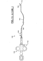
図1に示されるとおり、典型的な括約筋切開器100は、PTFE(ポリテトラフルオロエチレン)又は別の可撓性材料で作製されたポリマーチューブシャフト102を含む。駆動ワイヤとも呼ばれる導電性フィラメント104が、シャフト102を貫通して延びるルーメン106内に配置される。フィラメント104の遠位端は、シャフト102の遠位端に接続又は繋止される。導電性フィラメント104のその遠位端近傍の短い一部分はシャフト102の外側に配置され、電気焼灼カッティングワイヤ108として使用される。フィラメント104の近位端は近位ハンドルアセンブリ110に対し、ハンドルアセンブリ110を作動させるとフィラメント104がポリマーシャフト102に対して部分的に後退する(すなわち、近位方向に引かれる)ように接続される。この作動の結果、シャフト102の遠位端が曲がって円弧112を形成し、露出したフィラメントが円弧112の割線を形成することでカッティングワイヤ108を形成する。ハンドルアセンブリ110の電極114からフィラメント104に電流が流れることで、カッティングワイヤ108が、上記の手技例ではオッディ括約筋などの、組織の切断及び焼灼に効果的に用いられ得る電気手術切断要素として機能することが可能となる。
As shown in FIG. 1, a
括約筋切開器の使用中に起こり得る1つの問題は、オッディ括約筋に隣接した組織が不注意に切断され得ることである。具体的には、括約筋の周囲の乳頭組織は、襞状表面として隆起していることが多い。括約筋切開術においては、カニューレ挿入を可能とするために求められる括約筋組織のみを切開することが最も好ましい。しかしながら、カッティングワイヤ108のうち括約筋を実際に切開している部分に隣接する一部分によって、隣接する乳頭の襞が不注意に切断されたり、又はその他の形で損傷を受けたりし得る。起こり得る別の問題は、電流によって、露出したカッティングワイヤから内視鏡又は別の構造にアークが飛び得ることである。これが起こると、カッティングワイヤが破損して括約筋切開器が使えなくなったり、さらには1つ又は複数のワイヤ断片が剥がれ飛んだりする可能性さえあり、これは傷害の危険性をもたらし得る。こうした理由から、括約筋切開術に目的を定めた形で使用できるように、短いカッティングワイヤ部分のみを露出させることが望ましい。括約筋切開器の物理的な構造上の制約から、カッティングワイヤをそのようにするのに、十分短い円弧112にすることのみでは、これを達成することはできない。結果として、一部の括約筋切開器はカッティングワイヤに被覆部分を含むようになっている。こうした装置は、典型的にはスリーブの形態のPTFE又は別のポリマーを使用する。こうした被覆スリーブもまた欠点がある。例えば、通常の組立及び使用中、スリーブに切欠きが入るか、又はスリーブが裂けるかしたり(例えば、内視鏡のエレベータと接触することによって)、又はワイヤが露出して意図する絶縁効果が無効になるような形でスリーブが長手方向に移動したりし得る。このタイプのスリーブコーティングはまた、カッティングワイヤの外径も増加する。従って、望ましい電気絶縁性を提供し、破損に強く、且つカッティングワイヤ直径が大幅に増加することのない括約筋切開器ワイヤコーティングが必要とされている。
One problem that can occur during use of a sphincter incisor is that tissue adjacent to the oddy sphincter can be inadvertently cut. Specifically, papillary tissue around the sphincter often bulges as a saddle-like surface. In sphincterotomy, it is most preferable to cut only the sphincter tissue required to allow cannulation. However, the portion of the
本発明の実施形態は、括約筋切開器カッティングワイヤに対し、薄いながら耐久性のある電気絶縁コーティングを設けることによって前述の必要性に応えるポリマーコーティングを含む。 Embodiments of the present invention include a polymer coating that addresses the aforementioned needs by providing a thin but durable electrical insulating coating on the sphincterotome cutting wire.
一態様において、本発明は、被覆部分を含むカッティングワイヤを有する括約筋切開器を含み得る。被覆部分は、ポリ−p−キシリレン、2−クロロ−p−キシリレン、2,4−ジクロロ−p−キシリレン、ポリ(テトラフルオロ−p−キシリレン)、ポリ(カルボキシル−p−キシリレン−co−p−キシリレン)、フッ素化パリレン、パリレンHT、及びこれらの任意の組み合わせからなる群から選択されるコーティングなどのパリレンコーティングを含み得る。 In one aspect, the present invention may include a sphincter incisor having a cutting wire that includes a coated portion. The covering portion is made of poly-p-xylylene, 2-chloro-p-xylylene, 2,4-dichloro-p-xylylene, poly (tetrafluoro-p-xylylene), poly (carboxyl-p-xylylene-co-p- Xylylene), fluorinated parylene, parylene HT, and a parylene coating, such as a coating selected from the group consisting of any combination thereof.
別の態様において、本発明は、被覆部分を含むカッティングワイヤを有する括約筋切開器を含み得る。被覆部分は、静摩擦係数が約0.4未満のほぼ一様に結合した表面被覆材を提供し、カッティングワイヤと結合して電気絶縁層を提供するための、生体適合性ポリマーコーティング手段を含む。 In another aspect, the present invention can include a sphincter incisor having a cutting wire that includes a coated portion. The coated portion provides a substantially uniformly bonded surface coating having a coefficient of static friction of less than about 0.4 and includes a biocompatible polymer coating means for bonding with a cutting wire to provide an electrically insulating layer.
さらに別の態様において、本発明は、部分的に電気絶縁されたカッティングワイヤを有する括約筋切開器の作製方法を含み得る。本方法は、括約筋切開器カッティングワイヤを提供するステップと、次にカッティングワイヤの少なくとも一部分を、ポリ−p−キシリレン、2−クロロ−p−キシリレン、2,4−ジクロロ−p−キシリレン、ポリ(テトラフルオロ−p−キシリレン)、ポリ(カルボキシル−p−キシリレン−co−p−キシリレン)、フッ素化パリレン、パリレンHT、及びこれらの任意の組み合わせからなる群から選択されるポリマーコーティングで被覆するステップとを含む。本方法はまた、カッティングワイヤを括約筋切開器アセンブリに組み付けるステップも含む。 In yet another aspect, the present invention can include a method of making a sphincterotome having a partially electrically insulated cutting wire. The method comprises the steps of providing a sphincterotome cutting wire, and then at least a portion of the cutting wire is poly-p-xylylene, 2-chloro-p-xylylene, 2,4-dichloro-p-xylylene, poly ( Coating with a polymer coating selected from the group consisting of tetrafluoro-p-xylylene), poly (carboxyl-p-xylylene-co-p-xylylene), fluorinated parylene, parylene HT, and any combination thereof; including. The method also includes assembling the cutting wire to the sphincterotome assembly.
さらになお別の態様において、本発明は、シャフトと、前記シャフトのルーメンを通じて長手方向に配置された駆動ワイヤであって、その駆動ワイヤのうちシャフトの外側に露出した遠位カッティングワイヤ部分を除く、駆動ワイヤと、遠位シャフト部分を円弧状にする形で駆動ワイヤをシャフトに対して引っ張るように構成されたハンドルとを含む括約筋切開器を提供することによって、狭窄した構造にカニューレ挿入する方法を含み得る。遠位駆動ワイヤ部分は、電気絶縁された領域と、それに直接隣接する電気絶縁されていない切断領域とを含み得る。電気絶縁された領域は、ポリ−p−キシリレン、2−クロロ−p−キシリレン、2,4−ジクロロ−p−キシリレン、ポリ(テトラフルオロ−p−キシリレン)、ポリ(カルボキシル−p−キシリレン−co−p−キシリレン)、フッ素化パリレン、パリレンHT、及びこれらの任意の組み合わせからなる群から選択されるコーティングを含み得る。本方法はまた、カニューレ挿入を必要とする狭窄した構造に遠位括約筋切開領域を送り込むステップと、狭窄した構造を切断領域と接触させるステップと、切断領域に電流を送り込むステップとをも含む。 In still yet another aspect, the present invention provides a shaft and a drive wire disposed longitudinally through a lumen of the shaft excluding a portion of the drive wire that is exposed outside the shaft, A method of cannulating a constricted structure by providing a sphincter incisor that includes a drive wire and a handle configured to pull the drive wire relative to the shaft in an arcuate shape of the distal shaft portion. May be included. The distal drive wire portion may include an electrically isolated region and a non-electrically isolated cutting region immediately adjacent thereto. The electrically isolated regions are poly-p-xylylene, 2-chloro-p-xylylene, 2,4-dichloro-p-xylylene, poly (tetrafluoro-p-xylylene), poly (carboxyl-p-xylylene-co -P-xylylene), fluorinated parylene, parylene HT, and a coating selected from the group consisting of any combination thereof. The method also includes delivering a distal sphincter incision region to the constricted structure requiring cannulation, contacting the constricted structure with the cutting region, and delivering current to the cutting region.
以下の開示は、駆動ワイヤ部分と絶縁部分を有するカッティングワイヤ部分とを含む導電性ワイヤを含む、本発明に係る括約筋切開器の実施形態について記載する。当業者は、記載される実施形態の変形例及び等価物が本願の範囲内で実施され得ることを理解するであろう。 The following disclosure describes an embodiment of a sphincterostomy device according to the present invention that includes a conductive wire that includes a drive wire portion and a cutting wire portion having an insulating portion. Those skilled in the art will appreciate that variations and equivalents of the described embodiments may be practiced within the scope of the application.
図2〜2Aは本発明の括約筋切開器200を図示し、これは、例えば、PTFE又は同様に好適な材料で構成され得るポリマーチューブシャフト202を含む。導電性の駆動ワイヤ204がハンドルアセンブリ210からルーメン206を通じて長手方向に延在し、このルーメン206は、シャフト202の大部分の長さを貫通している。駆動ワイヤ204の最遠位端は、カニューレ205をはんだ付けすることによってシャフト202の遠位端近傍にある電気焼灼カッティングワイヤ208に取り付けられる。好ましい一実施形態において、カッティングワイヤ208は駆動ワイヤ204より小さい外径を有する。シャフト202の遠位端近傍にあるカッティングワイヤ208の短い長さ部分は、シャフト202の外側に延在する。括約筋切開器が作動していない状態のとき、駆動ワイヤ204はシャフト202の長手方向軸線とほぼ平行である。駆動ワイヤ204の近位端部分は好ましくは、ハンドルアセンブリ210を作動させると駆動ワイヤ204がシャフト202に対して近位方向に引かれるように、近位ハンドルアセンブリ210に接続される。この作動の結果、シャフト202の遠位部分が曲がって円弧212を形成し、露出したカッティングワイヤ部分208が円弧212の割線を形成することで横切カッティングワイヤ部分208を形成する。
FIGS. 2-2A illustrate a
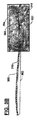
カッティングワイヤ208の一部分はポリマーコーティング220で被覆される。図では明確にする目的から、シャフト202の遠位領域が長手方向断面図として図2Aに拡大して示され、及びコーティング220の厚さは一定の尺度では図示されていない。加えて、図では明確にするため、シャフトのワイヤガイドルーメンは図示されず、それでも当業者は、多くの括約筋切開器が、ショートワイヤ及びロングワイヤ、或いはそのどちらか一方の適用向けに構成されたワイヤガイドルーメンを含むことを理解するであろう。本発明の好ましいコーティングは、百万分の1から千分の数インチの間の厚さであり得る。好ましいコーティングはまた、好ましくは摩擦係数が低く、電気絶縁性でもある。横切ワイヤ208の切断部分208aは被覆されないままとされる。このようにしてハンドルアセンブリ210の電極214から駆動ワイヤ204に電流が流れることで、切断部分208aが、組織(例えば、胆管系への到達を確保する括約筋切開手技においてはオッディ括約筋など)の切断及び焼灼に効果的に用いられ得る電気手術切断要素として機能することが可能となる。
A portion of the
切断部分208aは、ルーメン206から外側に露出しているカッティングワイヤ208の横切ワイヤ部分より短い。コーティング220は、隣接する組織に対するリスクを最小限に抑えて所望の組織のみを切開することに高度に目的化した形で切断部分208aを用いることができるような電気絶縁を提供する。例えば、本発明の括約筋切開器は、露出した横切ワイヤ部分が約20、25、又は30mmの長さであり、当該長さのうち約8〜約10mmが切断部分として使用されるように構成され且つ電気絶縁コーティングによる被覆がない、35cmのカッティングワイヤを含み得る。かかる括約筋切開器の実施形態において、コーティングはワイヤの長さの約5cmを被覆し得る。このコーティング長さによって、カッティングワイヤのより近位の被覆部分がルーメンの中に十分に延在するようになり、安全機能が提供される。多くの括約筋切開手技では、約8〜約10mmの切断部分が括約筋の切開に理想的な長さを提供し、それと同時に隣接する組織に損傷を与える可能性を最小限に抑える。当該技術分野において公知の、又は開発される方法で括約筋切開器のシャフト中に装着されたカッティングワイヤの最遠位部分は、被覆されても、又は被覆されなくともよい。
The
本出願人は、括約筋切開器ワイヤ用途に非常に高い効果を有するコーティング物質及び方法を発見した。極めて好ましいコーティングとして、パリレン−N(ポリ−p−キシリレン)が挙げられる。本発明に係る方法で用いられるとき、このコーティングは、例えばPTFEなどの既存のコーティングと比較して必要な材料が少なく、優れた電気絶縁性及び耐久性並びに費用上の利点を提供する。例えば、2−クロロ−p−キシリレン(パリレンC)、2,4−ジクロロ−p−キシリレン(パリレンD)、ポリ(テトラフルオロ−p−キシリレン)、ポリ(カルボキシル−p−キシリレン−co−p−キシリレン)、フッ素化パリレン、又はパリレンHT(登録商標)(ペルフルオロ化パリレン及び非フッ素化パリレンのコポリマー)を含む他のキシリレンポリマー、特にパリレンポリマーもまた、単独で、又は任意の組み合わせで本発明の範囲内のコーティングとして用いられ得る。本発明の好ましいコーティングは以下の特性を含み得る:低摩擦係数(好ましくは約0.5未満、より好ましくは約0.4未満、及び最も好ましくは約0.35未満);水分及び気体に対する極めて低い透過性;耐真菌性及び耐細菌性;高抗張力及び降伏強さ;高い形状適合性(不規則な表面を含め、あらゆる表面に対して空隙を残すことなく一様な厚さで塗着することが容易である);放射線耐性(蛍光透視下で有害な反応がない);生体適合性/生体不活性;耐酸性及び耐塩基性(酸性又は腐食性の流体による損傷がほとんど又は全くない);化学気相蒸着法による結合/組込みによってワイヤ表面に塗着可能(結合とは、例えば、下層のワイヤから剥離可能な表面皮膜を形成するフルオロエチレンとは対照的であることが意図される);及び高い絶縁耐力。パリレンコーティングは、特にこれらの性質を呈する。例えば、表1を参照のこと。

本発明の好ましい実施形態において、コーティング220は、化学気相蒸着法(「CVD」、これにはプラズマCVDプロセスを含んでもよい)によって駆動ワイヤ204に塗着される。化学気相蒸着法は電子回路の技術分野において周知の方法であり、ワイヤに対する−例えば−パリレンコーティングなどのコーティングの塗着に良く適合する。この方法によると、コーティングがワイヤに対し、その円周面に沿って平滑且つ一様に塗着される。パリレンコーティングを使用して被覆された駆動ワイヤは、コーティングの耐久性、費用の節減、及び外径の望ましさの点で利点を呈すると同時に、潤滑性(低摩擦性)及び電気絶縁性について優れた品質のコーティングを提供する。先行技術のコーティングとは対照的に、本発明の結合されたコーティングは、例えば内視鏡のエレベータ又はワイヤ係止機構などの別の表面との摩擦性又は外傷性の接触によって裂けたり、又はワイヤから剥がれたりすることがない。
In a preferred embodiment of the present invention, the
本発明の好ましい駆動ワイヤは導電性であり、ステンレス鋼、ニチノール、又は本発明の範囲内の別の導電材料で構成され得る。別の実施形態(図示せず)においては単一のワイヤが使用されてもよく、ここでは駆動ワイヤの遠位部分がカッティングワイヤとして使用され得る。かかる実施形態において、駆動ワイヤのカッティングワイヤ部分は低減した直径を含み得る。図2〜2Aを参照して記載される実施形態と同様に、カッティングワイヤの一部分の外径が低減していることにより、そこがより目的化された切断表面を形成することが可能となる。当然ながら、駆動ワイヤの外径は、それが継ぎ目なく連続的であるか、又は、カニューレ、溶接、又は他の何らかの接続手段によって接続されているかに関わらず、カッティングワイヤ部分の外径と実質的に同じであってもよい。 Preferred drive wires of the present invention are electrically conductive and may be composed of stainless steel, nitinol, or another conductive material within the scope of the present invention. In another embodiment (not shown), a single wire may be used, where the distal portion of the drive wire may be used as the cutting wire. In such embodiments, the cutting wire portion of the drive wire may include a reduced diameter. Similar to the embodiment described with reference to FIGS. 2-2A, the reduced outer diameter of a portion of the cutting wire allows it to form a more targeted cutting surface. Of course, the outer diameter of the drive wire is substantially the same as the outer diameter of the cutting wire portion, regardless of whether it is seamlessly continuous or connected by cannula, welding, or some other connection means. May be the same.
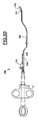
本発明の方法において、被覆された駆動ワイヤを使用する括約筋切開器が提供され得る。かかる方法の一実施形態が、図3A〜3Dを参照して示される。図3Aに示されるとおり、標準的な駆動ワイヤ300が提供され、近位部分302及び遠位部分304が取り外し可能な保護遮蔽材310で被覆される。近位部分302はワイヤ300の大部分の近位長さを含み、遠位部分304はワイヤ300の遠位端を含み、及びそれらの間に遮蔽されないワイヤ部分308が配置される。遮蔽されないワイヤ部分308の一部又は全てが、研削されるか、又はその他の方法でその外径が低減するように処理されてもよく、それによってそのカッティングワイヤ部分は、その他の駆動ワイヤ長さ部分と比較したとき、より小さい切断用の断面積を呈する。取り外し可能な保護遮蔽材310は、絶縁コーティングの塗着過程において駆動ワイヤ300を保護するために提供される。図3Bに図示されるとおり、次にパリレン又は他の適当なコーティングを含む絶縁コーティング320が、化学気相蒸着方法を用いて塗着される。この実施形態において、絶縁コーティング320は遮蔽されないワイヤ部分308に塗着され、電気絶縁されたワイヤ部分308を形成する。
In the method of the present invention, a sphincter incisor using a coated drive wire may be provided. One embodiment of such a method is shown with reference to FIGS. As shown in FIG. 3A, a
次に、図3Cに示されるとおり、駆動ワイヤ300から取り外し可能な保護遮蔽材310が取り除かれ得る。次に駆動ワイヤ300が括約筋切開器350に組み付けられ得る(図3Dを参照)。図3Dは、駆動ワイヤ300が括約筋切開器350に組み付けられるとき、電気絶縁されたワイヤ部分308が括約筋切開器シャフト352の駆動ワイヤルーメン354の外側に延在することを示す。シャフト352の外側に露出した駆動ワイヤ300の電気絶縁されていない部分は、括約筋切開器350の遠位先端354に直接隣接する。このようにして、上記のとおり、駆動ワイヤ300の電気絶縁されていない短い長さ部分がカッティングワイヤ部分312として利用されるように露出し、これは、全体が絶縁されていないカッティングワイヤと比べてより目的化された形で機能し得る。
Next, as shown in FIG. 3C, the removable
方法について記載される実施形態のように目的化した形でワイヤを被覆すると、望ましい電気絶縁コーティングが提供されると同時に、使用する電気絶縁コーティングも最小限となり、それに付随して費用が節減され得る。当業者は、他の実施形態において、駆動ワイヤのより長い−全長以下の−長さが電気絶縁コーティングで被覆されてもよいことを理解するであろう。これらの代替的実施形態において、コーティングの薄さ及び一様性は、その塗着が化学気相蒸着法によるか、又は別の方法によるかに関わらず、好ましくはワイヤ長さに沿って一定であり、しかし最も好ましくは、駆動ワイヤのうち、括約筋切開器シャフトの外側に露出するが、切断に使用することは意図されない領域(具体的には、駆動ワイヤのうちカッティングワイヤ部分に直接隣接し、且つ通常の動作中に括約筋切開器ルーメンの外側に露出する領域)における完全性を維持するコーティングを提供する。駆動ワイヤを括約筋切開器に組み付けるステップは、概して当該技術分野において公知である。 Covering the wire in a targeted manner as in the embodiments described for the method provides the desired electrical insulation coating while minimizing the electrical insulation coating used and concomitantly reducing costs. . One skilled in the art will appreciate that in other embodiments, a longer—less than full length—length of the drive wire may be coated with an electrically insulating coating. In these alternative embodiments, the thinness and uniformity of the coating is preferably constant along the wire length, regardless of whether the coating is by chemical vapor deposition or by another method. Yes, but most preferably, the area of the drive wire that is exposed outside the sphincter shaft but not intended for use in cutting (specifically, the drive wire is directly adjacent to the cutting wire portion, And a coating that maintains integrity in the area exposed to the outside of the sphincterotomy lumen during normal operation. The step of assembling the drive wire to the sphincterotome is generally known in the art.
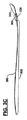
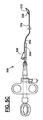
かかる方法の別の実施形態が、図5A〜5Cを参照して示される。図5Aに示されるとおり、カッティングワイヤ508が提供され、その近位部分502及び遠位部分504が取り外し可能な保護遮蔽材510で被覆される。取り外し可能な保護遮蔽材510は、絶縁コーティング塗着過程においてカッティングワイヤ508を覆うように提供され、遠位部分512は被覆が避けられる。次に、パリレン又は他の適切なコーティングを含む絶縁コーティング520が、化学気相蒸着方法を用いて塗着される。この実施形態において、絶縁コーティング520はカッティングワイヤ508の遮蔽されない部分に塗着される。
Another embodiment of such a method is shown with reference to FIGS. As shown in FIG. 5A, a
図5Bに図示されるとおり、次に駆動ワイヤ500が提供され、カニューレ509又は別の接続手段によってカッティングワイヤ508に取り付けられ得る(一定の尺度では図示されない)。駆動ワイヤ500もまた、取り外し可能な保護遮蔽材510が取り除かれてもよい。次に駆動ワイヤ500が括約筋切開器550に組み付けられ得る。図5Cは、駆動ワイヤ500が括約筋切開器550に組み付けられるとき、電気絶縁されたワイヤ部分508が括約筋切開器シャフト552の駆動ワイヤルーメン554の外側に延在することを示す。シャフト552の外側に露出したカッティングワイヤ508の電気絶縁されていない部分512は、括約筋切開器550の遠位先端554に直接隣接する。このようにして、上記のとおり、駆動ワイヤ500の電気絶縁されていない短い長さ部分512がカッティングワイヤ部分512として利用されるように露出し、これは、全体が絶縁されていないカッティングワイヤと比べてより目的化された形で機能し得る。図では明確にする目的から、カニューレ509及びコーティング520は一定の尺度では図示されていない。本発明の好ましいコーティングは、百万分の1から千分の数インチの間の厚さであり得る。
As illustrated in FIG. 5B, a
方法について記載される実施形態のように目的化された形でワイヤを被覆すると、望ましい電気絶縁コーティングが提供されると同時に、使用する電気絶縁コーティングも最小限となり、それに付随して費用が節減され得る。当業者は、他の実施形態において、駆動ワイヤのより長い−全長以下の−長さが電気絶縁コーティングで被覆されてもよいことを理解するであろう。これらの代替的実施形態において、コーティングの薄さ及び一様性は、その塗着が化学気相蒸着法によるか、又は別の方法によるかに関わらず、好ましくはワイヤ長さに沿って一定であり、しかし最も好ましくは、駆動ワイヤのうち、括約筋切開器シャフトの外側に露出するが、切断に使用することは意図されない領域(具体的には、駆動ワイヤのうちカッティングワイヤ部分に直接隣接し、且つ通常の動作中に括約筋切開器ルーメンの外側に露出する領域)における完全性を維持するコーティングを提供する。駆動ワイヤを括約筋切開器に組み付けるステップは、概して当該技術分野において公知である。 Covering the wire in a targeted manner as in the embodiment described for the method provides the desired electrical insulation coating, while minimizing the electrical insulation coating used and concomitantly reducing costs. obtain. One skilled in the art will appreciate that in other embodiments, a longer—less than full length—length of the drive wire may be coated with an electrically insulating coating. In these alternative embodiments, the thinness and uniformity of the coating is preferably constant along the wire length, regardless of whether the coating is by chemical vapor deposition or by another method. Yes, but most preferably, the area of the drive wire that is exposed outside the sphincter shaft but not intended for use in cutting (specifically, the drive wire is directly adjacent to the cutting wire portion, And a coating that maintains integrity in the area exposed to the outside of the sphincterotomy lumen during normal operation. The step of assembling the drive wire to the sphincterotome is generally known in the art.
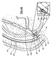
狭窄した構造にカニューレ挿入するための本発明の括約筋切開器の使用方法が括約筋切開術の実施形態において示されるとともに、ここで図4A〜4Bを参照して記載され、これは図2の括約筋切開器の実施形態を参照する。図4Aに示されるとおり、括約筋切開器200のシャフト202(その近位部分は、ハンドルを含め図示されない)が内視鏡400のワーキングチャンネル402を通じて送り込まれる。括約筋切開器200の遠位端が内視鏡400のエレベータ404によってある角度に曲げられ、総胆管456が十二指腸454に合流するファーター乳頭450に隣接する位置に至る。図4Aはまた、括約筋切開器200の遠位端部分が乳頭の襞450を通じてオッディ括約筋460の中まで、駆動ワイヤの切断部分208aが括約筋460に接触するまで送り込まれることも示す。図4Bに示されるとおり、次に括約筋切開器200を機械的にも電気的にも作動させ得る。機械的作動は、ハンドル(図示せず)を作動させて駆動ワイヤをシャフト202に対して引っ張り、それによって遠位シャフト212の円弧212を形成し、駆動ワイヤの横切ワイヤ208の部分でその割線を形成する典型的な括約筋切開器の方法を含む。横切ワイヤ208の切断部分208aが括約筋460に接触し、電気的作動(駆動ワイヤに電流を流すことを含む)によって、切断部分208aにより括約筋460を凝固させる切断がもたらされる。当業者は、本明細書に記載される他の構成のコーティングが本発明の範囲内で実施され得ることを理解するであろう。本発明の前述の実施形態で用いるのに適しているが、本明細書では詳細に説明されない特定の材料及び方法が、当業者には直ちに明らかであろう(例えば、マルチルーメン括約筋切開器で本発明の被覆ワイヤを使用するなど)。従って、前述の詳細な説明は、限定ではなく例示と見なされるべきであることが意図され、本発明の趣旨及び範囲を定義するよう意図されるのは、あらゆる等価物を含む以下の特許請求の範囲であることが理解されるべきである。
A method of using the sphincterotomy device of the present invention to cannulate a constricted structure is shown in a sphincteromyotomy embodiment and will now be described with reference to FIGS. 4A-4B, which is illustrated in FIG. Reference is made to the embodiment of the vessel. As shown in FIG. 4A, the
Claims (20)
を含む括約筋切開器であって、
前記被覆部分が、ポリ−p−キシリレン、2−クロロ−p−キシリレン、2,4−ジクロロ−p−キシリレン、ポリ(テトラフルオロ−p−キシリレン)、ポリ(カルボキシル−p−キシリレン−co−p−キシリレン)、フッ素化パリレン、パリレンHT、及びこれらの任意の組み合わせからなる群から選択されるコーティングを含む、括約筋切開器。 A sphincterostomy device including a cutting wire including a coated portion,
The covering portion is made of poly-p-xylylene, 2-chloro-p-xylylene, 2,4-dichloro-p-xylylene, poly (tetrafluoro-p-xylylene), poly (carboxyl-p-xylylene-co-p -Xylylene), a sphincter incisor comprising a coating selected from the group consisting of fluorinated parylene, parylene HT, and any combination thereof.
ルーメンを有し、且つ前記第1のハンドル部分に取り付けられる細長シャフトと、
前記第2のハンドル部分に取り付けられ、且つ前記ルーメンを通じて延在する駆動ワイヤであって、前記カッティングワイヤと接続される駆動ワイヤと、
をさらに含み、前記第1のハンドル部分と前記第2のハンドル部分とが、一方の他方に対する動きによって前記駆動ワイヤが前記シャフトに対して摺動して作動するように、互いに対して摺動自在に配置される、請求項1に記載の括約筋切開器。 A handle having a first handle portion and a second handle portion;
An elongated shaft having a lumen and attached to the first handle portion;
A drive wire attached to the second handle portion and extending through the lumen, the drive wire connected to the cutting wire;
And wherein the first handle portion and the second handle portion are slidable relative to each other such that the drive wire slides and operates relative to the shaft by movement relative to one of the other. The sphincter incisor according to claim 1, wherein
前記遠位カッティングワイヤ端部に隣接する約8〜約10mmの長さの被覆されないカッティングワイヤ部分と、
をさらに含む、請求項8に記載の括約筋切開器。 A distal cutting wire end mounted adjacent to the distal elongate shaft end;
An uncoated cutting wire portion of about 8 to about 10 mm length adjacent to the distal cutting wire end;
The sphincter incisor according to claim 8, further comprising:
を含む括約筋切開器であって、
前記被覆部分が、前記カッティングワイヤに結合して電気絶縁層を提供するための、静摩擦係数が約0.4未満のほぼ一様に結合した表面被覆材を提供する生体適合性ポリマーコーティング手段を含む、括約筋切開器。 A sphincterostomy device including a cutting wire including a coated portion,
The coated portion includes biocompatible polymer coating means for providing a substantially uniformly bonded surface coating having a coefficient of static friction of less than about 0.4 for bonding to the cutting wire to provide an electrically insulating layer. , Sphincterotome.
前記第1のハンドル部分に取り付けられた細長シャフトと、
前記第2のハンドル部分に取り付けられ、前記カッティングワイヤと接続された駆動ワイヤと、
をさらに含み、前記第1のハンドル部分と前記第2のハンドル部分とが、一方の他方に対する動きによって前記駆動ワイヤが前記シャフトに対して摺動して作動するように、互いに対して摺動自在に配置される、請求項13に記載の括約筋切開器。 A handle having a first handle portion and a second handle portion;
An elongated shaft attached to the first handle portion;
A drive wire attached to the second handle portion and connected to the cutting wire;
And wherein the first handle portion and the second handle portion are slidable relative to each other such that the drive wire slides and operates relative to the shaft by movement relative to one of the other. 14. A sphincterostomy device according to claim 13 disposed in
括約筋切開器カッティングワイヤを提供するステップと、
前記カッティングワイヤの少なくとも一部分を、ポリ−p−キシリレン、2−クロロ−p−キシリレン、2,4−ジクロロ−p−キシリレン、ポリ(テトラフルオロ−p−キシリレン)、ポリ(カルボキシル−p−キシリレン−co−p−キシリレン)、フッ素化パリレン、パリレンHT、及びこれらの任意の組み合わせからなる群から選択されるポリマーコーティングで被覆するステップと、
前記カッティングワイヤを括約筋切開器アセンブリに組み付けるステップと、
を含む、方法。 A method of making a sphincterotome having a partially electrically insulated cutting wire comprising:
Providing a sphincterotome cutting wire;
At least a part of the cutting wire is made of poly-p-xylylene, 2-chloro-p-xylylene, 2,4-dichloro-p-xylylene, poly (tetrafluoro-p-xylylene), poly (carboxyl-p-xylylene- coating with a polymer coating selected from the group consisting of: co-p-xylylene), fluorinated parylene, parylene HT, and any combination thereof;
Assembling the cutting wire to a sphincterotome assembly;
Including a method.
Applications Claiming Priority (2)
| Application Number | Priority Date | Filing Date | Title |
|---|---|---|---|
| US11/770,386 US8142431B2 (en) | 2007-06-28 | 2007-06-28 | Sphincterotome cutting wire improvement |
| PCT/US2008/068011 WO2009006100A2 (en) | 2007-06-28 | 2008-06-24 | Sphincterotome cutting wire improvement |
Publications (2)
| Publication Number | Publication Date |
|---|---|
| JP2010531712A true JP2010531712A (en) | 2010-09-30 |
| JP2010531712A5 JP2010531712A5 (en) | 2011-08-04 |
Family
ID=39645450
Family Applications (1)
| Application Number | Title | Priority Date | Filing Date |
|---|---|---|---|
| JP2010515031A Pending JP2010531712A (en) | 2007-06-28 | 2008-06-24 | Improved sphincterotome cutting wire |
Country Status (6)
| Country | Link |
|---|---|
| US (1) | US8142431B2 (en) |
| EP (1) | EP2170185B1 (en) |
| JP (1) | JP2010531712A (en) |
| AU (1) | AU2008270698B2 (en) |
| CA (1) | CA2691423C (en) |
| WO (1) | WO2009006100A2 (en) |
Cited By (3)
| Publication number | Priority date | Publication date | Assignee | Title |
|---|---|---|---|---|
| JP2018504215A (en) * | 2015-01-22 | 2018-02-15 | メドトロニック・ゾーメド・インコーポレーテッド | Corrosion-resistant magnetic article |
| JP2018533386A (en) * | 2015-11-20 | 2018-11-15 | ボストン サイエンティフィック サイムド,インコーポレイテッドBoston Scientific Scimed,Inc. | Drive handle for accessories |
| JP2021524790A (en) * | 2018-06-11 | 2021-09-16 | ボストン サイエンティフィック サイムド,インコーポレイテッドBoston Scientific Scimed,Inc. | How to use Sphinctero Tome and Sphinc Terror Tome |
Families Citing this family (12)
| Publication number | Priority date | Publication date | Assignee | Title |
|---|---|---|---|---|
| US8715281B2 (en) * | 2006-03-09 | 2014-05-06 | Olympus Medical Systems Corp. | Treatment device for endoscope |
| US8535310B2 (en) * | 2007-08-08 | 2013-09-17 | Cook Medical Technologies Llc | Sphincterotome |
| DE102008028410B4 (en) * | 2008-06-17 | 2011-04-07 | W.C. Heraeus Gmbh | Selective parylene coating for pacemaker electrodes |
| WO2010075425A1 (en) * | 2008-12-22 | 2010-07-01 | Wilson-Cook Medical, Inc. | Electrosurgical rotating cutting device |
| US9408662B2 (en) | 2012-05-07 | 2016-08-09 | Cook Medical Technologies Llc | Sphincterotome having expandable tines |
| US10806509B2 (en) | 2012-12-27 | 2020-10-20 | Cook Medical Technologies Llc | Method of adhering a conductive coating to an adhesion-resistant outer surface |
| US9844407B2 (en) | 2012-12-27 | 2017-12-19 | Cook Medical Technologies Llc | Bipolar sphincterotome |
| US11737851B2 (en) | 2018-06-28 | 2023-08-29 | Cook Medical Technologies Llc | Medical devices for magnetic resonance imaging and related methods |
| CN109480962B (en) * | 2018-12-20 | 2021-07-23 | 深圳开立生物医疗科技股份有限公司 | Cutting wire of cutting knife |
| WO2020142581A1 (en) * | 2019-01-03 | 2020-07-09 | Boston Scientific Scimed, Inc. | Devices, systems and methods for accessing a body lumen |
| US20210244466A1 (en) * | 2020-02-06 | 2021-08-12 | Covidien Lp | Electrosurgical device for cutting tissue |
| CN116058930B (en) * | 2023-03-06 | 2023-06-16 | 浙江首鼎医学科技有限公司 | Nipple incision knife based on incision density and incision advantage switching method thereof |
Citations (4)
| Publication number | Priority date | Publication date | Assignee | Title |
|---|---|---|---|---|
| JPS58152912U (en) * | 1982-04-06 | 1983-10-13 | 株式会社メドス研究所 | High frequency dissector for endoscope |
| JP2000237202A (en) * | 1999-02-25 | 2000-09-05 | Olympus Optical Co Ltd | Treating utensil for endoscope |
| JP2000262537A (en) * | 1999-03-16 | 2000-09-26 | Olympus Optical Co Ltd | Operative instrument for endoscope |
| JP2006511276A (en) * | 2002-12-20 | 2006-04-06 | マノア メディカル, インコーポレイテッド | System and method for cutting tissue |
Family Cites Families (13)
| Publication number | Priority date | Publication date | Assignee | Title |
|---|---|---|---|---|
| US4181131A (en) | 1977-02-28 | 1980-01-01 | Olympus Optical Co., Ltd. | High frequency electrosurgical instrument for cutting human body cavity structures |
| JPS6031690Y2 (en) * | 1981-12-11 | 1985-09-21 | 株式会社 メドス研究所 | High frequency dissector for endoscope |
| US4582067A (en) * | 1983-02-14 | 1986-04-15 | Washington Research Foundation | Method for endoscopic blood flow detection by the use of ultrasonic energy |
| US5241970A (en) * | 1991-05-17 | 1993-09-07 | Wilson-Cook Medical, Inc. | Papillotome/sphincterotome procedures and a wire guide specially |
| US5902272A (en) | 1992-01-07 | 1999-05-11 | Arthrocare Corporation | Planar ablation probe and method for electrosurgical cutting and ablation |
| US6030381A (en) * | 1994-03-18 | 2000-02-29 | Medicor Corporation | Composite dielectric coating for electrosurgical implements |
| US5743905A (en) * | 1995-07-07 | 1998-04-28 | Target Therapeutics, Inc. | Partially insulated occlusion device |
| US5810807A (en) * | 1996-05-22 | 1998-09-22 | Ganz; Robert A. | Sphincterotome with deflectable cutting plane and method of using the same |
| US5746746A (en) * | 1996-08-30 | 1998-05-05 | Garito; Jon C. | Electrosurgical electrode and method for skin resurfacing |
| US6432104B1 (en) | 1998-04-15 | 2002-08-13 | Scimed Life Systems, Inc. | Electro-cautery catherer |
| US6021355A (en) | 1998-10-29 | 2000-02-01 | Ethicon, Inc. | Surgical electrode having a partially insulated needle |
| US20040034275A1 (en) * | 2002-07-29 | 2004-02-19 | Peter Forsell | Multi-material incontinence treatment constriction device |
| EP1660165B1 (en) * | 2003-07-31 | 2008-06-04 | Wilson-Cook Medical Inc. | System for introducing multiple medical devices |
-
2007
- 2007-06-28 US US11/770,386 patent/US8142431B2/en active Active
-
2008
- 2008-06-24 CA CA2691423A patent/CA2691423C/en active Active
- 2008-06-24 AU AU2008270698A patent/AU2008270698B2/en active Active
- 2008-06-24 EP EP08771817A patent/EP2170185B1/en active Active
- 2008-06-24 WO PCT/US2008/068011 patent/WO2009006100A2/en active Application Filing
- 2008-06-24 JP JP2010515031A patent/JP2010531712A/en active Pending
Patent Citations (4)
| Publication number | Priority date | Publication date | Assignee | Title |
|---|---|---|---|---|
| JPS58152912U (en) * | 1982-04-06 | 1983-10-13 | 株式会社メドス研究所 | High frequency dissector for endoscope |
| JP2000237202A (en) * | 1999-02-25 | 2000-09-05 | Olympus Optical Co Ltd | Treating utensil for endoscope |
| JP2000262537A (en) * | 1999-03-16 | 2000-09-26 | Olympus Optical Co Ltd | Operative instrument for endoscope |
| JP2006511276A (en) * | 2002-12-20 | 2006-04-06 | マノア メディカル, インコーポレイテッド | System and method for cutting tissue |
Cited By (6)
| Publication number | Priority date | Publication date | Assignee | Title |
|---|---|---|---|---|
| JP2018504215A (en) * | 2015-01-22 | 2018-02-15 | メドトロニック・ゾーメド・インコーポレーテッド | Corrosion-resistant magnetic article |
| JP2018533386A (en) * | 2015-11-20 | 2018-11-15 | ボストン サイエンティフィック サイムド,インコーポレイテッドBoston Scientific Scimed,Inc. | Drive handle for accessories |
| US11206968B2 (en) | 2015-11-20 | 2021-12-28 | Boston Scientific Scimed, Inc. | Actuation handle for accessory devices |
| JP2021524790A (en) * | 2018-06-11 | 2021-09-16 | ボストン サイエンティフィック サイムド,インコーポレイテッドBoston Scientific Scimed,Inc. | How to use Sphinctero Tome and Sphinc Terror Tome |
| US11517371B2 (en) | 2018-06-11 | 2022-12-06 | Boston Scientific Scimed, Inc. | Sphincterotomes and methods for using sphincterotomes |
| JP7350786B2 (en) | 2018-06-11 | 2023-09-26 | ボストン サイエンティフィック サイムド,インコーポレイテッド | How to use a sphincterotome and a sphincterotome |
Also Published As
| Publication number | Publication date |
|---|---|
| WO2009006100A2 (en) | 2009-01-08 |
| CA2691423C (en) | 2012-12-18 |
| AU2008270698A1 (en) | 2009-01-08 |
| EP2170185B1 (en) | 2013-03-13 |
| WO2009006100A3 (en) | 2009-12-23 |
| AU2008270698B2 (en) | 2013-03-07 |
| EP2170185A2 (en) | 2010-04-07 |
| US8142431B2 (en) | 2012-03-27 |
| US20090005778A1 (en) | 2009-01-01 |
| CA2691423A1 (en) | 2009-01-08 |
Similar Documents
| Publication | Publication Date | Title |
|---|---|---|
| JP2010531712A (en) | Improved sphincterotome cutting wire | |
| US7449022B2 (en) | Shapeable electrosurgical scalpel | |
| JP6117422B2 (en) | Open irrigation ablation catheter | |
| US20070123964A1 (en) | Magnetically guidable energy delivery apparatus and method of using same | |
| AU2010284405B2 (en) | Echogenic electrosurgical device | |
| JP5531352B2 (en) | Catheter assembly | |
| EP2811921B1 (en) | Cutting tool with circulating wire | |
| US20090138009A1 (en) | Magnetically guided energy delivery apparatus | |
| US9023040B2 (en) | Electrosurgical cutting devices | |
| JP5670572B2 (en) | Cautery overtube | |
| JP2007175521A (en) | Linear ablation device and assembly | |
| JP2014529427A (en) | Cautery cap | |
| EP2263585A1 (en) | Thermal barrier for suction coagulator | |
| EP3030133B1 (en) | Continuous compound curved tip for cannulation | |
| JP2009539552A (en) | Wire guide sphincterotome | |
| JP2009539552A5 (en) | ||
| CA3147059A1 (en) | Endoscopic catheter device | |
| WO2017173606A1 (en) | Bipolar incision knife | |
| JP4634619B2 (en) | Endoscopic high-frequency snare | |
| AU2014271219B2 (en) | Ablation overtube |
Legal Events
| Date | Code | Title | Description |
|---|---|---|---|
| A521 | Request for written amendment filed |
Free format text: JAPANESE INTERMEDIATE CODE: A523 Effective date: 20110617 |
|
| A621 | Written request for application examination |
Free format text: JAPANESE INTERMEDIATE CODE: A621 Effective date: 20110617 |
|
| A711 | Notification of change in applicant |
Free format text: JAPANESE INTERMEDIATE CODE: A711 Effective date: 20120313 |
|
| A131 | Notification of reasons for refusal |
Free format text: JAPANESE INTERMEDIATE CODE: A131 Effective date: 20121127 |
|
| A02 | Decision of refusal |
Free format text: JAPANESE INTERMEDIATE CODE: A02 Effective date: 20130423 |