JP2010527652A - Packaged orthodontic appliances and adhesives - Google Patents
Packaged orthodontic appliances and adhesives Download PDFInfo
- Publication number
- JP2010527652A JP2010527652A JP2010508473A JP2010508473A JP2010527652A JP 2010527652 A JP2010527652 A JP 2010527652A JP 2010508473 A JP2010508473 A JP 2010508473A JP 2010508473 A JP2010508473 A JP 2010508473A JP 2010527652 A JP2010527652 A JP 2010527652A
- Authority
- JP
- Japan
- Prior art keywords
- orthodontic
- adhesive
- appliance
- chamber
- packaged
- Prior art date
- Legal status (The legal status is an assumption and is not a legal conclusion. Google has not performed a legal analysis and makes no representation as to the accuracy of the status listed.)
- Withdrawn
Links
Images


Classifications
-
- A—HUMAN NECESSITIES
- A61—MEDICAL OR VETERINARY SCIENCE; HYGIENE
- A61C—DENTISTRY; APPARATUS OR METHODS FOR ORAL OR DENTAL HYGIENE
- A61C7/00—Orthodontics, i.e. obtaining or maintaining the desired position of teeth, e.g. by straightening, evening, regulating, separating, or by correcting malocclusions
- A61C7/12—Brackets; Arch wires; Combinations thereof; Accessories therefor
- A61C7/14—Brackets; Fixing brackets to teeth
- A61C7/16—Brackets; Fixing brackets to teeth specially adapted to be cemented to teeth
-
- A—HUMAN NECESSITIES
- A61—MEDICAL OR VETERINARY SCIENCE; HYGIENE
- A61C—DENTISTRY; APPARATUS OR METHODS FOR ORAL OR DENTAL HYGIENE
- A61C2202/00—Packaging for dental appliances
Abstract
パッケージ化された歯科矯正アセンブリは、チャンバを備える容器と、チャンバ内に収容される歯科矯正装具とを含む。一定量の第1歯科矯正接着剤は、製造者により歯科矯正装具の基部に塗布される。第2歯科矯正接着剤もまた、当初は第1歯科矯正接着剤と相対的に間隔をあけてチャンバ内に収容される。歯科医は、所望の際に、第1歯科矯正接着剤を第2歯科矯正接着剤に接触するように選択できる。 The packaged orthodontic assembly includes a container with a chamber and an orthodontic appliance housed within the chamber. A quantity of the first orthodontic adhesive is applied by the manufacturer to the base of the orthodontic appliance. The second orthodontic adhesive is also initially housed in the chamber at a distance relative to the first orthodontic adhesive. The dentist can select the first orthodontic adhesive to contact the second orthodontic adhesive when desired.
Description
本発明は概して、歯科矯正治療中に患者の歯に施す歯科矯正装具及び接着剤に関する。より詳細には、本発明は、患者の歯を所望の位置に移動させるのに用いる1つ以上の歯科矯正装具及び接着剤を包含するパッケージ化されたアセンブリに関する。 The present invention relates generally to orthodontic appliances and adhesives applied to a patient's teeth during orthodontic treatment. More particularly, the present invention relates to a packaged assembly that includes one or more orthodontic appliances and adhesives used to move a patient's teeth to a desired position.
歯科矯正治療は、位置異常歯を歯科矯正学的に正しい位置に移動させるものである。ブラケットとして知られる小さな歯科矯正装具は患者の歯の外面に連結され、アーチワイヤは各ブラケットのスロット中に配置される。アーチワイヤーは、正しい咬合をもたらすために、歯を所望の位置に移動するように誘導する経路を形成させる。アーチワイヤの末端部は、患者の大臼歯に固定されるバッカルチューブとして知られる装具に受け入れられることが多い。 Orthodontic treatment is to move an abnormally positioned tooth to an orthodontic correct position. A small orthodontic appliance known as a bracket is connected to the outer surface of the patient's teeth and an archwire is placed in the slot of each bracket. The archwire forms a path that guides the teeth to move to the desired position to provide correct occlusion. The distal end of the archwire is often received in an appliance known as a buccal tube that is secured to the patient's molar teeth.
最近では、ダイレクトボンディング法又はインダイレクトボンディング法のいずれかを利用し、接着剤を用いて歯科矯正装具を歯のエナメル質表面に接着することが、一般的な手法になってきた。接着剤は、装具が歯に配置される直前に、歯科医により装具基部に塗布されることが多い。場合によっては、一定量の接着剤を混合パッド又は分注ウェルに取り出した後、小型のスパチュラやその他の手用器具を用いて各装具に接着剤を軽く塗りつける。他の例としては、一定量の接着剤を注射剤から装具基部に直接取り出す。 Recently, it has become common practice to use either a direct bonding method or an indirect bonding method to bond an orthodontic appliance to the tooth enamel surface using an adhesive. The adhesive is often applied to the appliance base by the dentist just before the appliance is placed on the teeth. In some cases, after a certain amount of adhesive has been removed to the mixing pad or dispensing well, the adhesive is lightly applied to each appliance using a small spatula or other hand instrument. As another example, a fixed amount of adhesive is removed directly from the injection to the appliance base.
接着剤で予めコーティングされたブラケットは周知であり、矯正歯科医にとって極めてメリットが大きい。接着剤で予めコーティングされたブラケットは、製造者が正確な量の光硬化性接着剤のような接着剤を塗布しているボンディングベースを有する。ダイレクトボンディング法では、接着剤で予めコーティングされたブラケットの歯への装着が望まれる際、単純にパッケージからブラケットを取り出し、直接歯に配置する。インダイレクトボンディング法では、ブラケットをパッケージから取り出して、例えば、患者の歯列弓の複製しっくい又は「石膏」模型上に置いて、一般的には転移トレー又はインダイレクトボンディングトレーを用い、患者の歯に後で装着するための個別調製基部を提供する。 Brackets pre-coated with an adhesive are well known and have great benefits for orthodontists. The adhesive pre-coated bracket has a bonding base on which the manufacturer has applied an accurate amount of adhesive, such as a photo-curable adhesive. In the direct bonding method, when it is desired to attach a bracket pre-coated with an adhesive to a tooth, the bracket is simply removed from the package and placed directly on the tooth. In the indirect bonding method, the bracket is removed from the package and placed, for example, on a replica plaster or “gypsum” model of the patient's dental arch, typically using a transfer tray or indirect bonding tray. Provides a separately prepared base for later mounting.
接着剤で予めコーティングされた歯科矯正装具は、光、水分及び汚染物質から接着剤を保護する容器中にパッケージ化されることが多い。既知の容器としては、装具を1個のみ収容する容器が挙げられる。接着剤は、製造者が装具基部にコーティングしており、容器内の剥離面にあることが多い。剥離面は、装具を容器から持ち上げるとき、接着剤の全体形状を必要以上に崩さずに、接着剤からの取り外しを容易にする特徴を有する。 Orthodontic appliances pre-coated with an adhesive are often packaged in a container that protects the adhesive from light, moisture and contaminants. Known containers include containers that contain only one appliance. The adhesive is often coated on the appliance base by the manufacturer and is on the release surface in the container. The release surface has features that facilitate removal from the adhesive without unnecessarily disrupting the overall shape of the adhesive when the appliance is lifted from the container.
しかし場合によっては、製造者が装具基部に塗布する接着剤量とは異なる量の歯科矯正接着剤の使用を、歯科医が好む場合がある。例えば、歯面に装具を押し付ける際、装具基部からはみ出る接着剤の「はみ出し」を取り除く時間が少なくてすむように、比較的少量の接着剤による装具ボンディングを好む歯科医がいる。対照的に、別の歯科医は、装具を歯面に置いた後、装具基部と患者の歯のエナメル質との間に間隙や空隙ができないようにするために、装具のボンディングの際に、より多量の接着剤の使用を好む。 However, in some cases, dentists may prefer to use an amount of orthodontic adhesive that is different from the amount of adhesive that the manufacturer applies to the appliance base. For example, some dentists prefer to bond an appliance with a relatively small amount of adhesive so that when the appliance is pressed against the tooth surface, it takes less time to remove the “sticking” of adhesive protruding from the appliance base. In contrast, another dentist, when placing the appliance on the tooth surface, when bonding the appliance to prevent a gap or gap between the appliance base and the patient's tooth enamel. Prefer the use of higher amounts of adhesive.
更に、改善された機能特性を有する新たな歯科矯正接着剤の開発が、長い間取り組まれてきた。そのような特性の例としては、フッ化物の徐放性、耐湿性及び変色特性が挙げられる。残念ながら、従来の歯科矯正向けにパッケージされた一部の接着剤を使用しても、得られるアセンブリの貯蔵寿命が比較的短いため、完全な満足は得られない。異なる接着剤と使用可能な予めコーティングされた装具向けのパッケージ構成体の提供は、大きな利点があることが理解されるだろう。 Furthermore, the development of new orthodontic adhesives with improved functional properties has been addressed for a long time. Examples of such properties include fluoride sustained release, moisture resistance and discoloration properties. Unfortunately, the use of some adhesives packaged for conventional orthodontics is not entirely satisfactory because the shelf life of the resulting assembly is relatively short. It will be appreciated that providing a package structure for a pre-coated appliance that can be used with different adhesives has significant advantages.
本発明は、少なくとも1つの装具が、2種の当初は異なる量の接着剤とともに容器内のチャンバに収容されることを特徴とする、パッケージ化された歯科矯正アセンブリ及び関連方法に関する。接着剤のうち一方は製造者により装具基部に塗布され、所望の際に、装具が患者の歯にボンディングされる前に、容器中の別の接着剤と接触させられる。 The present invention relates to a packaged orthodontic assembly and related method characterized in that at least one appliance is housed in a chamber in a container with two initially different amounts of adhesive. One of the adhesives is applied to the appliance base by the manufacturer and, if desired, brought into contact with another adhesive in the container before the appliance is bonded to the patient's teeth.
より詳細には、1つの態様において本発明は、チャンバを備える容器とチャンバ内に収容される歯科矯正装具とを含む、パッケージ化された歯科矯正アセンブリを目的とする。装具には、基部と、装具基部に広がる第1歯科矯正接着剤とが含まれる。アセンブリはまた、チャンバ内剥離面及び剥離面に受けられる第2歯科矯正接着剤も含む。第2歯科矯正接着剤は、第1歯科矯正接着剤から間隔をあけてチャンバ内に収容される。 More particularly, in one aspect, the present invention is directed to a packaged orthodontic assembly that includes a container comprising a chamber and an orthodontic appliance housed within the chamber. The appliance includes a base and a first orthodontic adhesive that spreads over the appliance base. The assembly also includes an in-chamber release surface and a second orthodontic adhesive received on the release surface. The second orthodontic adhesive is received in the chamber spaced from the first orthodontic adhesive.
本発明の別の態様は、歯科矯正装具をパッケージ化する方法を目的とする。本方法は、歯科矯正装具と装具の基部に広がる第1歯科矯正接着剤を提供することと、一定量の第2歯科矯正接着剤をチャンバを備える容器に配置することと、第1歯科矯正接着剤が第2歯科矯正接着剤から間隔をあけるように、チャンバ内に歯科矯正装具を保持することと、を含む。 Another aspect of the invention is directed to a method of packaging an orthodontic appliance. The method provides an orthodontic appliance and a first orthodontic adhesive that extends to the base of the appliance, placing an amount of a second orthodontic adhesive in a container with a chamber, and a first orthodontic adhesive. Holding the orthodontic appliance in the chamber such that the agent is spaced from the second orthodontic adhesive.
本発明の更なる態様は、歯科矯正装具への歯科矯正接着剤の塗布方法を目的とする。本方法は、歯科矯正装具と装具の基部に広がる第1歯科矯正接着剤を提供することと、容器のチャンバ内に歯科矯正装具を保持することと、チャンバ内に第2歯科矯正接着剤を配置することと、容器のカバーを閉じることと、続いてカバーを開けて装具を露出させることと、第1接着剤を第2接着剤に接触する状態にするために、チャンバ内で装具及び第2歯科矯正接着剤を相対的に移動させることと、を含む。 A further aspect of the present invention is directed to a method of applying an orthodontic adhesive to an orthodontic appliance. The method provides an orthodontic appliance and a first orthodontic adhesive that extends to the base of the appliance, retains the orthodontic appliance in a chamber of the container, and places a second orthodontic adhesive in the chamber. Closing the cover of the container, subsequently opening the cover to expose the appliance, and bringing the first adhesive into contact with the second adhesive and the second appliance in the chamber. Relatively moving the orthodontic adhesive.
1つの選択肢としては、第1歯科矯正接着剤が第2歯科矯正接着剤と同一であり、装具基部上の接着剤の総量の増加が望まれる場合に、歯科医が第1接着剤を第2接着剤に接触させるようにできる。別の選択肢としては、例えば化学反応を開始したり、及び/又は生じる接着剤組成物の特性を向上させたりするために、第1接着剤は第2接着剤と、組成物、粘度及び/又はその他の特性の点で異なってもよい。 One option is that if the first orthodontic adhesive is the same as the second orthodontic adhesive and the total amount of adhesive on the appliance base is desired to be increased, the dentist will replace the first adhesive with the second one. It can be brought into contact with the adhesive. Another option is that the first adhesive is combined with the second adhesive, the composition, viscosity and / or, for example, to initiate a chemical reaction and / or improve the properties of the resulting adhesive composition. Other characteristics may be different.
本発明の更なる詳細は、特許請求の範囲の特徴によって規定される。 Further details of the invention are defined by the features of the claims.
定義
「近位側」は、患者の湾曲した歯列弓の中心に向かう方向を意味する。
Definitions “Proximal” means in a direction toward the center of the patient's curved dental arch.
「遠位側」は、患者の湾曲した歯列弓の中心から離れる方向を意味する。 “Distal” means in a direction away from the center of the patient's curved dental arch.
「咬合側」は、患者の歯の外側先端部に向かう方向を意味する。 “Occlusal side” means the direction toward the outer tip of the patient's teeth.
「歯肉側」は、患者の歯茎又は歯肉に向かう方向を意味する。 “Gingival side” means the direction toward the patient's gums or gums.
「顔面側」は、患者の頬又は唇に向かう方向を意味する。 “Facial side” means the direction toward the patient's cheek or lips.
「舌側」は、患者の舌に向かう方向を意味する。 “Lingual” means in a direction toward the patient's tongue.
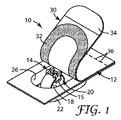
本発明の1つの実施形態によるパッケージ化された歯科矯正アセンブリを図1〜4に図示し、数字10で表す。アセンブリ10は、容器12、容器12に収容される歯科矯正装具14、装具14に広がる一定量の第1歯科矯正接着剤15、剥離面16、剥離面16に受けられる一定量の第2歯科矯正接着剤18及び容器12中で装具14を支える支持体20を一般的に含む。
A packaged orthodontic assembly according to one embodiment of the present invention is illustrated in FIGS. The
より詳細には、容器12には、楕円形の側壁22及び底部24が含まれる。側壁22及び底部24はチャンバ26を画定する。側壁22の上縁は、チャンバ26を取り囲むフランジ28につながる。
More particularly, the
好ましくは、側壁22、底部24、及びフランジ28は、一体的に成型され、又は一体型コンポーネントとして成形される。好適な材料としては、米国特許第5,328,363号(チェスター(Chester)ら)に記載されるような、ポリエチレンテレフタレートグリコール(「PETG」)が挙げられる。任意に、公開済みの米国特許出願第2003/0196914号(ツォウ(Tzou)ら)に記載されるような、金属粒子と混合されている高分子材料を使用してもよい。
Preferably, the
更に容器12は、フランジ28に接着剤部分32により取り外し可能に接続されるカバー30も含む。カバー30の好適な材料は、上記米国特許第5,328,363号(チェスター(Chester)ら)、及び米国特許公開第2003/0196914号(ツォウ(Tzou)ら)に記載されている。接着剤32に好適な材料は、米国特許第5,328,363号(チェスター(Chester)ら)、及び同第6,960,079号(ブレナン(Brennan)ら)に記載されている。別の方法としては、カバー30をヒートシールによりフランジ28に接続してもよい。
The
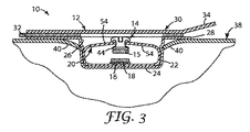
カバー30を、図2及び3では閉鎖位置で示し、図4では開放位置で示す。閉鎖位置では、カバー30はチャンバ26の開口部に広がり、光、水分、及び汚染物質への露出に対する装具14及び接着剤15、18の保護に役立つ。カバー30は、フランジ28を超えて広がるつまみ34を含み、これはカバー30の閉鎖位置から開放位置への移動が望まれるとき、歯科医が掴むためのものである。
The
任意に、カバー30は一連のミシン目36(図1)を含み、直立の開放位置の状態でのカバー30の自立保持を促進し、カバー30が比較的硬質の材料で製造できるようにする。また、ミシン目36が提供されることにより、歯科医がカバー30を引っ張り続け、カバー30をフランジ28から分離しないようにするために、カバー30が開放状態であることを歯科医に感触で伝える。
Optionally, the
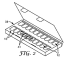
任意に、容器12は、別の容器と共に、図2に例示するキャリア38のようなキャリア中に収容される。キャリア38は、一連の楕円形開口部41(図2)を画定する、縁部構造40(図3及び4)を有する。好ましくは、キャリア38は2列の開口部41を有し、各列に10か所の開口部41を含む。この方法で、容器12と類似する、歯科矯正治療に関与する各非大臼歯に対応する20個の容器を収容する空間が提供される。別の方法として、大臼歯向けの装具14も提供するような場合には、キャリア38は各列14か所の開口部41を含む2列の開口部を含んでもよい。
Optionally,
容器12の側壁22には2か所の凹部42(図3及び4)が含まれ、縁部構造40の一部を収容するため水平方向に延びる。望みどおりに容器12を開口部に挿入し、又は開口部から取り外せるように、縁部構造は可撓性である。図3及び4に示すように、容器12が開口部内に収容されるとき、縁部構造40はわずかに変形又は屈折している。通常では、容器12に十分な力がかかり、所望の際に、開口部からの容器12の取り外しとキャリア38からの分離ができるにもかかわらず、屈折した縁部構造40は開口部内の容器12を引き続いて保持する。
The
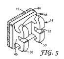
図1、3、及び4に例示される装具14を単独で、第1接着剤15と共に図5中に示す。この実施形態では装具14は歯科矯正ブラケットであるが、バッカルチューブ、ボタン、及びその他歯のアタッチメントなど別の装具も可能である。
The
装具14には、外又は底表面が歯の方向を向く、基部44が含まれる。第1接着剤15は、基部44の外表面に広がる。本体46は基部44から外方向にのび、2本の咬合側結合ウィング48及び2本の歯肉側結合ウィング50につながる。アーチワイヤスロット52は本体46にまたがり、アーチワイヤを収めるため結合ウィング48、50間のすき間内にある。
The
任意に、基部44は、患者の歯面形状に正確に適合する個別調製した形状を有する。個別調製基部の製造方法は、米国特許第5,971,754号(ソンティ(Sondhi)ら)及び同第7,188,421号(クリアリー(Cleary)ら)に記載されている。一例として、個別調製基部44を第1接着剤15と同じ硬化性接着剤を用いて形成してもよい。その他の構成も可能である。
Optionally, the
図中に示す装具14は、「ツイン結合ウィング」ブラケットである。「シングル結合ウィング」ブラケットなどのその他ブラケットでもよい。更に、ブラケットは、図に示すもの以外の形状を有してもよい。ブラケットを、金属(例えばステンレス鋼)、プラスチック(例えば任意にガラスファイバーで充填されたポリカーボネート)又はセラミック(例えば単結晶又は多結晶アルミナ)などを含むいくつかの材料のどれか1つで製造してもよい。
The
支持体20はチャンバ12内に収容され、装具14に取り外し可能に接続される。この実施形態では、支持体20は、全体として概ね「C」型で、中央部が底部24に付着する形状を有する。支持体20は、互いに向かって延びる2本のアーム54を含む。アーム54の外端部は互いに間隔があけられ、装具14を収容するチャネル又は受け口が存在する。装具14が受け口の中に収容されるとき、一方のアーム54は、咬合側結合ウィング48の裏側の凹部(すなわち、結合ウィング48と基部44との間の領域)に位置し、もう一方のアーム54は、歯肉側結合ウィング50の裏側の凹部に位置する。
The
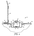
支持体20は可撓性材料で作られており、復原力を十分に有し、図3及び4に示すように、装具14の基部44を、第2接着剤18に対して間隔をあけて通常は保持する。好ましくは、容器12のカバー30が、図3に示す閉じた位置から図4に示す開いた位置に移動するとき、支持体20の復原力により、アーム54が第2接着剤18から離れる方向へ移動するように、支持体20の全体形状を変更させる。好ましくは、図4に示すように、支持体20が弛緩した形状のとき、装具14はチャンバ26の外側にあり、フランジ28の上方の位置にある。
The
支持体20の好適な材料の例として、ポリエチレン、ポリプロピレン、ポリエチレンテレフタレート(「PET」)、ポリエチレンテレフタレートグリコール(「PETG」)、及びナイロンなどの可撓性高分子材料が挙げられる。
Examples of suitable materials for the
剥離面16は、その「C」型形状の中央部付近にある支持体20の底部に広がり、装具14の基部44に向かう方向に、上向きに面する。剥離面16は、当初は第2接着剤18を保持している。しかし、所望のときに第2接着剤18が剥離面16にほとんど残らないようにして、剥離面16は第2接着剤18を容易に解放する。剥離面16は、第2接着剤18の全体形状に必要以上のひずみを起こさせずに、第2接着剤18を取り外すことができることが好ましい。
The
接着剤15、18は、液体、半液体、ペースト、又は接着処置中に液体、半液体、若しくはペーストに変換される固体材料であってよい。好適な組成物としては、組成物、コンポマー類、ガラスアイオノマー類、及び樹脂で変性されたガラスアイオノマー類などが挙げられる。光硬化性接着剤の例としては、スリーエム・ユニテック(3M Unitek)製のトランスボンド(Transbond)XTブランド及びトランスボンド(Transbond)LRブランドの接着剤が挙げられる。化学硬化性接着剤の例としては、スリーエム・ユニテック(3M Unitek)製の、ソンティ(Sondhi)ブランドのラピッド・セット(Rapid-Set)インダイレクトボンディング接着剤、ユナイト(Unite)ブランドの接着剤、及びコンサイス(Concise)ブランドの接着剤が挙げられる。光硬化性接着剤及び化学硬化性接着剤の両方の接着剤の例は、スリーエム・ユニテック(3M Unitek)製のマルチ・キュア(Multi-Cure)ブランドのガラスアイオノマーセメントである。 The adhesive 15, 18 may be a liquid, semi-liquid, paste, or a solid material that is converted to a liquid, semi-liquid, or paste during the bonding procedure. Suitable compositions include compositions, compomers, glass ionomers, glass ionomers modified with resins, and the like. Examples of photocurable adhesives include Transbond XT brand and Transbond LR brand adhesives manufactured by 3M Unitek. Examples of chemically curable adhesives include 3M Unitek's Sondhi brand Rapid-Set indirect bonding adhesives, Unite brand adhesives, and Concise brand adhesives. An example of both a light curable adhesive and a chemically curable adhesive is Multi-Cure brand glass ionomer cement from 3M Unitek.
接着剤15、18が、上述の化学硬化性接着剤などの2成分接着剤のそれぞれ第1及び第2構成成分である場合、第1及び第2構成成分は、当初、容器12を運搬及び保管する間は、図3に示すように、互いに接触しない状態にするのが有利である。任意に、構成成分の1つが凍結乾燥のイオン性セメントを含有する場合、米国特許第6,050,815号(アダム(Adam)ら)に記載される方法により、そのセメントを基部44に固定してもよい。
If the
本発明の接着剤15、18に有用な組成物は、当業者には周知である。有用な組成物として、例えば、光硬化性及び化学硬化性歯科矯正接着剤の両方が挙げられる。いくつかの実施形態では、組成物は、好ましくは、フッ化物放出接着剤、セルフエッチング接着剤、セルフプライミング接着剤、変色接着剤及びこれらの組み合わせである。
Compositions useful for the
任意に、歯の治療に対する歯科医の好みに応じて、各接着剤15、18を以下のクラスに分ける。 Optionally, depending on the dentist's preference for dental treatment, each adhesive 15, 18 is divided into the following classes:
クラスI:歯のエナメル質のエッチングと、歯のエナメル質へのプライマーの別途適用の両方が必要な接着剤。 Class I: Adhesives that require both tooth enamel etching and separate application of a primer to the tooth enamel.
クラスII:エッチングは必要であるが、プライマーの別途適用は不要な接着剤。 Class II: An adhesive that requires etching but does not require separate application of a primer.
クラスIII:洗浄以外は歯の処置が不要な接着剤。 Class III: An adhesive that does not require any dental treatment other than cleaning.
化学硬化性接着剤の一部を含むクラスI接着剤は、リン酸又はビスホスホン酸などの好適なエッチング液の使用を必要とする。クラスI接着剤と共に使用可能なプライマーとしては、スリーエム・ユニテック(3M Unitek)製のトランスボンド(Transbond)MIPブランドのプライマー及びトランスボンド(Transbond)XTブランドのプライマー、並びにオームコ社(Ormco Corporation)製のオルト・ソロ(Ortho Solo)ブランドのプライマーなどの歯科矯正に対するプライマーが挙げられる。スリーエム・ユニテック(3M Unitek)製のトランスボンド・プラス(Transbond Plus)SEPブランドのプライマーなど、セルフエッチングプライマーが使用できる可能性もある。プライマーは任意に、歯に十分なプライマーが塗布されたかを確認するための光退色性色素、処置中のフッ化物放出のための少量のフルオロアルミナ(fluoroalumina)ケイ酸塩ガラス(「FAS」ガラス)、レオロジー制御のための少量のヒュームドシリカ、及び/又は、破壊靭性向上にのための少量のシラン化石英充填剤を、含んでもよい。 Class I adhesives that include a portion of a chemically curable adhesive require the use of a suitable etchant such as phosphoric acid or bisphosphonic acid. Primers that can be used with Class I adhesives include 3M Unitek Transbond MIP brand primers and Transbond XT brand primers, as well as those from Ormco Corporation. Examples include orthodontic primers such as Ortho Solo brand primers. Self-etching primers may also be used, such as Transbond Plus SEP brand primers from 3M Unitek. The primer is optionally a photobleachable dye to verify that enough primer has been applied to the teeth, a small amount of fluoroalumina silicate glass ("FAS" glass) for fluoride release during treatment Small amounts of fumed silica for rheology control and / or small amounts of silanized quartz filler for improved fracture toughness may be included.
好適なクラスII接着剤には多くの従来の光硬化性接着剤が含まれ、別途プライミング工程を必要としない。接着剤が多層接着剤の場合、接着剤は、接着処置中に最初に歯に接触するプライマー層を含んでもよい。上述のように、リン酸又はビスホスホン酸をエッチング液として使用してもよい。接着剤がプライマー成分を含まない場合、エッチング液自体がプライマーとして機能してもよい。このようなセルフエッチングプライマーの例は、スリーエム・ユニテック(3M Unitek)製のトランスボンド・プラス(Transbond Plus)SEPブランドのプライマーである。任意に、セルフエッチングプライマーは、クラスI接着剤において上述した任意の機能を採用することもあり得る。 Suitable class II adhesives include many conventional photocurable adhesives and do not require a separate priming step. If the adhesive is a multi-layer adhesive, the adhesive may include a primer layer that first contacts the teeth during the bonding procedure. As described above, phosphoric acid or bisphosphonic acid may be used as an etchant. When the adhesive does not contain a primer component, the etching solution itself may function as a primer. An example of such a self-etching primer is a Transbond Plus SEP brand primer from 3M Unitek. Optionally, the self-etching primer may employ any of the functions described above in class I adhesives.
好適なクラスIII接着剤は、歯のエッチング及びプライミングの必要がなく、「自己接着性」組成物と呼ばれることがある。これらの接着剤を使用すると、歯科医に必要となるのは、典型的な接着処置中、歯科用装具の装着前に歯の洗浄を行うのみである。好適なクラスIII接着剤として、リン酸メタクリレート(例えば、モノ−HEMAリン酸、ジ−HEMAリン酸、グリセロールジメタクリレート(GDMA)リン酸)、ビスホスホン酸の水又は他の溶媒の溶液、及び粉末状のビスホスホン酸(歯みがき(tooth prophy)とすすぎの後、歯に残る水をイオン化に使用)から選択される酸性成分を挙げることができる。その他のクラスIII接着剤として、酸性官能基を含むエチレン性不飽和成分、酸性官能基を含まないエチレン性不飽和成分、反応開始剤系、及び充填剤を挙げることができる。任意に、クラスIII接着剤は、本質的に水を含まなくてもよい。クラスIII接着剤の例は、例えば公開済みの米国特許出願第2005/0176844号(オーセン(Aasen)ら)、同第2005/0175966号(ファルサフィ(Falsafi)ら)及び同第2005/0175965号(クレイグ(Craig)ら)に以前より記載されている。 Suitable class III adhesives do not require tooth etching and priming and are sometimes referred to as “self-adhesive” compositions. Using these adhesives, the dentist only needs to clean the teeth prior to wearing the dental appliance during a typical bonding procedure. Suitable class III adhesives include phosphate methacrylates (eg mono-HEMA phosphate, di-HEMA phosphate, glycerol dimethacrylate (GDMA) phosphate), solutions of bisphosphonic acid in water or other solvents, and powders And an acidic component selected from bisphosphonic acids (tooth prophy and rinsing followed by water remaining in the teeth for ionization). Other class III adhesives can include ethylenically unsaturated components that contain acidic functional groups, ethylenically unsaturated components that do not contain acidic functional groups, reaction initiator systems, and fillers. Optionally, the Class III adhesive may be essentially free of water. Examples of class III adhesives include, for example, published US Patent Application Nos. 2005/0176844 (Aasen et al.), 2005/0175966 (Falsafi et al.) And 2005/0175965 (Craig). (Craig) et al.).
上述のクラスIII接着剤は、任意に充填剤(例えば、通常のガラスアイオノマー固定反応中に水に結合するガラスアイオノマー型充填剤)を組み込むことができる。更に、任意の上述のクラスIII接着剤は、クラスI接着剤に関連して記載した任意の特性を採用することができる。 The class III adhesives described above can optionally incorporate fillers (eg, glass ionomer type fillers that bind to water during normal glass ionomer fixation reactions). Further, any of the above-described class III adhesives can employ any of the properties described in connection with class I adhesives.
本発明に有用な接着剤は、例えば、米国特許第3,814,717号(ウィルソン(Wilson)ら)及び同第6,126,922号(ロッツィ(Rozzi)ら)に記載されるフッ化物放出剤、例えば、国際公開第00/69393号(ブレナン(Brennan)ら)で開示される接着剤増強剤(例えば、チタン酸塩、ジルコン酸塩)、充填剤、微小充填剤、再石灰化剤、酵素放出剤、レオロジー増強剤、光退色性色素、示温剤及びこれらの組み合わせなどの成分を任意に含んでもよい。 Adhesives useful in the present invention are, for example, fluoride release as described in US Pat. Nos. 3,814,717 (Wilson et al.) And 6,126,922 (Rozzi et al.). Agents, such as adhesive enhancers (eg titanates, zirconates) disclosed in WO 00/69393 (Brennan et al.), Fillers, microfillers, remineralizing agents, Components such as an enzyme release agent, a rheology enhancer, a photobleachable dye, a temperature indicator, and combinations thereof may optionally be included.
任意に、接着剤15、18の一方又は両方は、好ましくは、歯科用構造体とは明確に異なる初期色を有する。色は、好ましくは、光退色性色素を使用して接着剤15、18に与えられる。接着剤15、18は、好ましくは、接着剤の総重量に基づき、少なくとも0.001重量%の光退色性色素を、より好ましくは少なくとも0.002重量%の光退色性色素を、含む。接着剤15、18は、好ましくは、接着剤の総重量に基づき、多くとも1重量%の光退色性色素を、より好ましくは多くとも0.1重量%の光退色性色素を、含む。光退色性色素の量は、その減衰係数、初期色を識別する人間の目の能力、及び所望の色変化によって異なる。
Optionally, one or both of the
光退色性色素の発色及び退色特性は、様々な因子、例えば、酸強度、誘電率、極性、酸素量、環境湿度、充填剤及び/又は樹脂の種類及び重量パーセントなどによって変わる。しかしながら、染料の退色特性は、接着剤を照射し、色の変化を評価することで容易に決定することができる。好ましくは、少なくとも1つの光漂白性染料は、少なくとも部分的に硬化性樹脂に可溶である。 The color development and color fading characteristics of the photobleachable dye vary depending on various factors such as acid strength, dielectric constant, polarity, oxygen content, environmental humidity, filler and / or resin type and weight percent. However, the fading characteristics of the dye can be easily determined by irradiating the adhesive and evaluating the color change. Preferably, the at least one photobleachable dye is at least partially soluble in the curable resin.
光退色性染料の代表的な型は、例えば、米国特許第6,331,080号(コール(Cole)ら)、同第6,444,725号(トロム(Trom)ら)、及び同第6,528,555号(ニクトウスキィ(Nikutowski)ら)に記載されている。好ましい色素としては、例えば、ローズベンガル(Rose Bengal)、メチレンバイオレット(Methylene Violet)、メチレンブルー(Methylene Blue)、フルオレセイン(Fluorescein)、エオシンイエロー(Eosin Yellow)、エオシンY(Eosin Y)、エチルエオシン(Ethyl Eosin)、エオシンブルイッシュ(Eosin bluish)、エオシンB(Eosin B)、エリスロシンB(ErythrosinB)、エリスロシンイエロー調ブレンド(Erythrosin Yellowish Blend)、トルイジンブルー(Toluidine Blue)、4’,5’−ジブロモフルオレセイン(4’,5’-Dibromofluorescein)、及びこれらの組み合わせが挙げられる。リアクティント(Reactint)染料も使用してよい。 Representative types of photobleachable dyes are described, for example, in US Pat. Nos. 6,331,080 (Cole et al.), 6,444,725 (Trom et al.), And , 528, 555 (Nikutowski et al.). Preferred dyes include, for example, Rose Bengal, Methylene Violet, Methylene Blue, Fluorescein, Eosin Yellow, Eosin Y, Ethyl Eosine. Eosin), Eosin bluish, Eosin B, Erythrosin B, Erythrosin Yellowish Blend, Toluidine Blue, 4 ', 5'-Dibromofluorescein ( 4 ', 5'-Dibromofluorescein), and combinations thereof. Reactint dyes may also be used.
接着剤15、18の色変化は、好ましくは光で開始される。好ましくは、色変化は、化学放射線照射によって、例えば、可視光又は近赤外(IR)光を発する歯科用硬化光を十分な時間にわたって照射することによって開始される。本発明の接着剤15、18の色変化を開始するメカニズムは、硬化メカニズムが樹脂を硬化するのとは別々であっても、又はほぼ同時であってもよい。例えば、重合が化学的に開始される(例えば酸化還元によって開始される)場合又は熱によって開始される場合、接着剤15、18が硬化してもよく、初期色から最終的な色への色変化は、化学放射線を照射した際に硬化プロセスに続いて起こってもよい。
The color change of the adhesive 15, 18 is preferably initiated with light. Preferably, the color change is initiated by irradiation with actinic radiation, for example by irradiation with a dental curing light emitting visible or near infrared (IR) light for a sufficient time. The mechanism that initiates the color change of the
初期色から最終的な色への接着剤の色変化は、好ましくは、以下に記載する色試験で定量化する。色試験を用いて、3次元色空間における全体の色変化を示すΔE*の値が測定される。人間の目は、通常の光条件下で約3ΔE*単位の色変化を検出できる。本発明の歯科用接着剤は、好ましくは、少なくとも10ΔE*である色変化を有することができ、より好ましくはΔE*が少なくとも15であり、最も好ましくはΔE*が少なくとも20である。 The color change of the adhesive from the initial color to the final color is preferably quantified by the color test described below. Using a color test, a value of ΔE * is measured that represents the overall color change in a three-dimensional color space. The human eye can detect a color change of about 3ΔE * units under normal light conditions. The dental adhesives of the present invention can preferably have a color change that is at least 10ΔE * , more preferably ΔE * is at least 15, and most preferably ΔE * is at least 20.
本発明の1つの実施形態では、接着剤15、18は組成及び特性的に同一である。第1接着剤15は、患者の歯に装具14を接着するのに十分で、比較的少量の第1接着剤15が残るように製造者が事前に決定した量で存在する。したがって、接着処置中、装具14が歯科医により歯面に押し付けられるとき、比較的少量の接着剤が装具基部44の側面に沿ってはみ出る。その結果、このような接着剤のはみ出しを取り除く時間が削減される。
In one embodiment of the invention, the
しかし、歯科医が、第1接着剤15の量を超える量の接着剤を用いて装具14の患者の歯への接着を望む場合、歯科医は、少なくとも一部の第2接着剤18を第1接着剤15に追加するために、容器12の中で下向きに歯科医から離れる方向へ装具14を押すことを選択できる。この歯科医による第2接着剤18の使用決定は、例えば、装具14と患者の歯との間に、確実に間隙や空隙(これらがあると、装具14の接着強度を過度に弱めたり、及び/又は、食物が集まる傾向がある空洞を存在させることになる)をなくすために歯科医が好適だとすることによってよい。別の例として、患者の歯の表面が不規則な形状であったり、接着剤を堆積して装具14をある方向に保持することを望む場合に、歯科医が第2接着剤18の使用を選択してもよい。
However, if the dentist wishes to bond the
本発明の別の実施形態では、第1接着剤15は、組成及び/又は特性の点で、第2接着剤18の組成及び特性と異なっている。例えば、第2接着剤18はプライマーを含み、より低粘度の湿潤剤を提供してもよい。任意に、プライマーは、湿潤剤並びに反応性セルフエッチング部分を提供するセルフエッチングプライマーである。別の実施形態では、第2接着剤18は、上述のような一定量の光退色性色素を含有するプライマーである。
In another embodiment of the present invention, the
任意に、第2接着剤18は、第1接着剤15の特性を増強する液体組成物である。例えば、第1接着剤15の位置に移されるとき、第2接着剤18は、第1接着剤15の粘着度を増加させることができ、第1接着剤15の湿潤性を増加させることができ、及び/又は第1接着剤15の耐湿性を増強することができる。これら増強された特性により装具14の接着を容易にし、歯科矯正治療中に装具14が自然に剥離する可能性を低くすることもできる。
Optionally, the
第2接着剤18を含む特に好ましい液体組成物として、一部の市販の液体歯科矯正用プライマーなど、第1接着剤15に相溶する親水性組成物が挙げられる。好適なプライマーの例は、スリーエム・ユニテック(3M Unitek)製のトランスボンド(Transbond)MIPブランドのプライマーである。液体組成物は、1種以上のモノマー、オリゴマー、ポリマー、若しくはコポリマー、又はこれらの混合物を含んでもよい。また、液体組成物は、顔料、酸化防止剤及び/又は硬化剤(接着剤18の硬化性を増強する目的)などの添加剤も含有してよい。液体組成物は、任意に、ヒュームドシリカ又は石英ガラス、フルオロアルミノケイ酸塩、石英、ジルコニアなどの固体充填剤粒子を含有し、充填剤粒子は、任意に、例えばシラン、ジルコン酸塩又はチタン酸塩コーティングで、分散助剤としてコーティングする場合もある。また、液体組成物はフッ化亜鉛などのフッ化物放出材料も含んでよい。その他可能性のある再石灰化剤として、非晶質リン酸カルシウム、カゼインリンペプチド、及びこれらの複合体が挙げられる。別の選択肢として、液体組成物は、抗菌剤、及び/又は歯に接触させたときに歯のエナメル質にエッチングを施す材料を含んでもよい。 Particularly preferred liquid compositions containing the second adhesive 18 include hydrophilic compositions that are compatible with the first adhesive 15 such as some commercially available liquid orthodontic primers. An example of a suitable primer is the Transbond MIP brand primer from 3M Unitek. The liquid composition may comprise one or more monomers, oligomers, polymers, or copolymers, or mixtures thereof. The liquid composition may also contain additives such as pigments, antioxidants and / or curing agents (for the purpose of enhancing the curability of the adhesive 18). The liquid composition optionally contains solid filler particles such as fumed silica or quartz glass, fluoroaluminosilicate, quartz, zirconia, and the filler particles optionally include, for example, silane, zirconate or titanic acid. In some cases, it is coated with a salt coating as a dispersion aid. The liquid composition may also include a fluoride releasing material such as zinc fluoride. Other possible remineralization agents include amorphous calcium phosphate, casein phosphopeptide, and complexes thereof. As another option, the liquid composition may include an antimicrobial agent and / or a material that etches the tooth enamel when contacted with the tooth.
好ましくは、液体組成物として、任意に水分吸収能を有し、更に歯のエナメル質への化学接着を増強する、親水性のモノマー、オリゴマー、ポリマー又はこれらのブレンドが挙げられる。好ましくは、強力な接着が形成されるように、液体組成物と第1接着剤15の境界面で硬化が行われる。好ましくは、接着剤が硬化するにつれ、液体組成物が第1接着剤15を「硬化」する、すなわち、液体組成物は第1接着剤15と共に重合する。第1接着剤15が硬化するとき、液体組成物は第1接着剤15に完全に又は部分的に架橋される。更に、液体組成物は、接着剤が硬化する前に、接着剤に必要以上に混合したり溶解したりしないように、好ましくは長期間にわたり第1接着剤15と実質的に不混和性である。
Preferably, the liquid composition includes hydrophilic monomers, oligomers, polymers or blends that optionally have moisture absorption and further enhance chemical adhesion of teeth to enamel. Preferably, curing is performed at the interface between the liquid composition and the first adhesive 15 so that a strong bond is formed. Preferably, as the adhesive cures, the liquid composition “cures” the
液体組成物に好ましい耐湿性材料又は親水性材料として、2−ヒドロキシエチルアクリレート、2−ヒドロキシエチルメタクリレート(「HEMA」)、ヒドロキシプロピルアクリレート、ヒドロキシプロピルメタクリレート、グリセロールジ−アクリレート、グリセロールジ−メタクリレート、ポリエチレングリコールモノメタクリレート、ポリプロピレングリコールモノメタクリレート、テトラヒドロフルフリルアクリレート、テトラヒドロフルフリルメタクリレート、グリシジルアクリレート、グリシジルメタクリレートなどが挙げられる。その他の好ましい親水性モノマーとして、グリセロールモノ−及びジ−アクリレート、グリセロールモノ−及びジ−メタクリレート、エチレングリコールジアクリレート、エチレングリコールジメタクリレート、ポリエチレングリコールジアクリレート(エチレンオキシド単位の繰り返し数は2〜30)、ポリエチレングリコールジメタクリレート(エチレンオキシド単位の繰り返し数は2〜30、特にトリエチレングリコールジメタクリレート(「TEGDMA」)が挙げられる。 Preferred moisture resistant or hydrophilic materials for liquid compositions include 2-hydroxyethyl acrylate, 2-hydroxyethyl methacrylate ("HEMA"), hydroxypropyl acrylate, hydroxypropyl methacrylate, glycerol di-acrylate, glycerol di-methacrylate, polyethylene Examples include glycol monomethacrylate, polypropylene glycol monomethacrylate, tetrahydrofurfuryl acrylate, tetrahydrofurfuryl methacrylate, glycidyl acrylate, and glycidyl methacrylate. Other preferred hydrophilic monomers include glycerol mono- and di-acrylate, glycerol mono- and di-methacrylate, ethylene glycol diacrylate, ethylene glycol dimethacrylate, polyethylene glycol diacrylate (the number of repeating ethylene oxide units is 2 to 30), Examples include polyethylene glycol dimethacrylate (the number of repeating ethylene oxide units is 2 to 30, particularly triethylene glycol dimethacrylate (“TEGDMA”)).
より限定的な親水性材料の例は、非イオン性ポリマー又はコポリマーであり、例えば、ポリアルキレンオキシド(ポリオキシメチレン、ポリエチレンオキシド、ポリプロピレンオキシド)、ポリエーテル(ポリビニルメチルエーテル)、ポリエチレンイミンコポリマー、ポリアクリルアミド及びポリメタクリルアミド、ポリビニルアルコール、鹸化ポリビニルアセテート、ポリビニルピロリドン、ポリビニルオキサゾリドン、並びにN−オキシスクシンイミド基を含むポリマーである。親水性材料のその他の例として、ポリアクリル酸、非イオン化の状態、部分的に中和された状態、又は完全に中和された状態のポリメタクリル酸、ポリエチレンイミン及びその塩、非イオン化の状態、部分的に中和された状態、又は完全に中和された状態のポリエチレンスルホン酸及びポリアリールスルホン酸、非イオン化の状態、部分的に中和された状態、又は完全に中和された状態のポリリン酸及びポリホスホン酸を含む、イオン性又はイオン化ポリマー及びコポリマーが挙げられる。 Examples of more restrictive hydrophilic materials are nonionic polymers or copolymers, such as polyalkylene oxides (polyoxymethylene, polyethylene oxide, polypropylene oxide), polyethers (polyvinyl methyl ether), polyethyleneimine copolymers, poly Acrylamide and polymethacrylamide, polyvinyl alcohol, saponified polyvinyl acetate, polyvinyl pyrrolidone, polyvinyl oxazolidone, and polymers containing N-oxysuccinimide groups. Other examples of hydrophilic materials include polyacrylic acid, non-ionized, partially neutralized, or fully neutralized polymethacrylic acid, polyethyleneimine and salts thereof, non-ionized Polyethylene sulfonic acid and polyaryl sulfonic acid in a partially neutralized state or in a fully neutralized state, non-ionized state, partially neutralized state or fully neutralized state And ionic or ionized polymers and copolymers including polyphosphoric acid and polyphosphonic acid.
好ましい親水性材料は、例えば、酸性、塩基性、又は塩の状態である極性基を含有するアクリレート、メタクリレート、クロトネート、イタコネートなどのビニルモノマーの反応により調製してもよい。これらの基はまた、イオン性又は中性であってもよい。 Preferred hydrophilic materials may be prepared, for example, by reaction of vinyl monomers such as acrylates, methacrylates, crotonates, itaconates containing polar groups that are acidic, basic, or salted. These groups may also be ionic or neutral.
極性又は分極性基の例としては、ヒドロキシ、チオ、置換及び非置換アミドのような中性基、環状エーテル類(オキサン類、オキセタン類、フラン類及びピラン類のような)、塩基性基(ホスフィン類及び、一級、二級、三級アミン類を含むアミン類のような)、酸性基(酸素酸類及び、C、S、P、Bのチオ酸素酸類(thiooxyacids)のような)、及びイオン性基(四級アンモニウム、カルボン酸塩、スルホン酸塩等のような)、並びにこれらの基の前駆体及び保護形態が挙げられる。 Examples of polar or polarizable groups include neutral groups such as hydroxy, thio, substituted and unsubstituted amides, cyclic ethers (such as oxanes, oxetanes, furans and pyrans), basic groups ( Phosphines and amines including primary, secondary and tertiary amines), acidic groups (such as oxygen acids and C, S, P, B thiooxyacids) and ions Sex groups (such as quaternary ammonium, carboxylates, sulfonates, etc.), as well as precursors and protected forms of these groups.
第2接着剤18として他に可能性がある液体組成物として、疎水性材料が挙げられる。好適な疎水性材料の例としては、ビスフェノールAジグリシジルエーテルジメタクリレート(bisGMA)、エトキシル化2ビスフェノールAジメタクリレート(bisEMA6)、エトキシル化6ビスフェノールAジメタクリレート(ジアクリル(Diacryl)101、すなわちbisEMA2)が挙げられる。 Other possible liquid compositions for the second adhesive 18 include hydrophobic materials. Examples of suitable hydrophobic materials include bisphenol A diglycidyl ether dimethacrylate (bisGMA), ethoxylated 2 bisphenol A dimethacrylate (bisEMA6), ethoxylated 6 bisphenol A dimethacrylate (Diacryl 101, ie bisEMA2). Can be mentioned.
剥離面16の特に好ましい材料として、連続気泡構造又は独立気泡構造のいずれかを有するポリマー発泡体が挙げられる。独立気泡発泡体が好ましい。剥離面16は、好ましくは圧縮性で、好ましくは弾性を有する。
A particularly preferred material for the
好ましくは、剥離面16の上部側に、完全にではないにしろほとんどが約0.001mm(0.00005インチ)〜約0.8mm(0.03インチ)の範囲内にある直径を有する孔を有する。より好ましくは、孔の直径は、完全にはないにしろほとんどが約0.02mm(0.001インチ)〜約0.2mm(0.01インチ)の範囲内である。好適な平均孔径の例は、直径0.1mm(0.004インチ)、あるいは約0.15mm(0.006インチ)〜約0.2mm(0.01インチ)の範囲内である。孔径は、上側平面に対して平行の基準平面における、孔の直径を測定することにより決定する。基準平面内で孔が円形ではない場合、この基準平面内の孔の面積に等しい面積を示す円の直径を計算することにより、孔径を決定する。
Preferably, the top side of the
剥離面16に特に好ましい発泡体材料としては、ポリエチレン発泡体、ポリブチレン発泡体、及びポリプロピレン発泡体、又はこれらのブレンドなどのポリオレフィン発泡体が挙げられる。ポリ塩化ビニル発泡体、ポリウレタン発泡体、及び発泡体コポリマーも使用可能である。好適なポリエチレン発泡体の例として、ボルテック(Voltek)製のLシリーズ、Mシリーズ、Sシリーズ、及びTシリーズの(Minicel)ブランドの発泡体(例えば、シリーズM200、M300、及びT300)が挙げられる。その他の好適な発泡体は、ボルテック(Voltek)製のボラーラ(Volara)ブランド9EOの薄く切り取った発泡体である。任意に、発泡体の気泡の外部層を加熱し、孔径を縮小することにより、及び/又は上部平面に垂直の方向に孔深さを縮小することにより、孔の寸法を「密封」つまり圧縮することができる。
Particularly preferred foam materials for the
選択した発泡体が第2接着剤18の1種以上の流体成分を徐々に吸収する場合、発泡体の剥離特性が必要以上に損なわれないのであれば、発泡体をある程度変性させることもあり得る。例えば、剥離面16の上面に、有機又は無機のバリア材料を融合又はコーティングし、孔の一部又は全部を部分的に閉じる場合もある。任意に、バリア材料は、硬化又は部分的に硬化され、発泡体材料の上面、発泡体材料本体、又はその両方に架橋されたバリアを形成する硬化性モノマー系である。別の選択肢として、発泡体は、それ以上の吸収力を低減させる液体成分にコーティングされ、又は部分的にコーティングされる(場合により浸漬される)。
If the selected foam gradually absorbs one or more fluid components of the
あるいは、剥離面16を別の材料で作製してもよい。例えば、剥離面16を、ポリエステル、ポリオレフィン、ポリウレタン、フルオロポリマー、(メタ)アクリル酸、シリコーン、エポキシ、合成ゴム、ポリカーボネート又はビニルなど、その他のポリマー、コポリマー、又はポリマー及びコポリマーのブレンドから作製することができる。剥離面16を、セラミック、ガラス、又は金属から作製することもできる。任意に、支持体20への別個のコーティング又は層の適用が不要となるように、接着剤15に面する支持体20の内側表面は剥離面16を呈示し、この場合、表面エネルギーが低いコーティング、例えばシリコーンやフルオロポリマーが支持体20に塗布され、第2接着剤18の剥離を容易にできる。
Alternatively, the
剥離面16を上記発泡体以外の材料で製造するとき、上述の好ましい実施形態における任意の孔は、任意のその他好適なプロセス又は構造を用いて作製してもよい。例えば、いくつかの粒子、例えば、ガラス、セラミック、金属、又はその他の材料で作製した球形又は不規則形のビーズ、破片、又は粒子を、剥離面16の裏側層に固定し、孔を提供してもよい。他の方法としては、上面に、隆起部、突起部、又はその他の構造を、ランダム又は反復で有し、いくつかの小孔を提供してもよい。これらの孔は、米国特許第5,152,917号(ピーパー(Pieper)ら)及び同第5,500,273号(ホームズ(Holmes)ら)に開示される方法など、ミクロ複製技術を用いて作製してもよい。
When the
任意に、剥離面16はその上面に広がる一定量の液体組成物を含み、第2接着剤18と接触する。液体組成物は、液体が連続した層であってもよいし、パターン付き若しくは印刷されたコーティング、又はランダムに塗布されたコーティングなど非連続層でもよい。液体組成物は、所望の際に剥離面16から第2接着剤18が剥離するのを容易にする任意の液体材料で製造されてよく、硬化性の場合は、アセンブリ10中で存在するとき、硬化されていなくても、部分的に硬化されていても、完全に硬化されていてもよい。
Optionally, the
好ましくは、第2接着剤18が剥離面16から外されるとき、液体組成物は少なくとも部分的に剥離基材から取り除かれ、患者の歯へ装具14を接着している間、第2接着剤18に残る。
Preferably, when the
その他の構成体や材料など、剥離面16に関する更なる情報は、米国特許第6,183,249号(ブレナン(Brennan)ら)に見出すことができる。好適な親水性材料に関する更なる情報は、1999年5月13日に出願された米国特許出願第09/311606号(ブレナン(Brennan)ら)に見出すことができる。任意に、剥離面16は支持体20の一部を含んでもよいし、又は支持体20に塗布されるコーティングであってもよい。
Additional information regarding the
第2接着剤18の剥離面16への有用な塗布法として、例えば、アシムテック(Asymtek)(カリフォルニア州、カールズバッド(Carlsbad))から商品名オートムーブ(Automove)で入手可能な自動化流体投与システムを用いる方法が挙げられる。このような自動流体投与システムは、パターン付き及びパターンなしのコーティング及び層の双方を投与するのに有用である。インクジェットプリンターなどのインクジェット分与システムも、パターン付き及びパターンなしの液体コーティング及び層を投与するのに有用である。他の有用なシステムとしては、例えば、米国特許第6,513,897号(トキー(Tokie))に記載されたような、例えばピストン分与システム及び多重解像度流体アプリケータが挙げられる。製造者により接着剤(例えば第1接着剤15)で予めコーティングされた装具14の例として、スリーエム・ユニテック社(3M Unitek Corporation)製のAPCブランドの接着剤で予めコーティングされた装具が挙げられる。
A useful method for applying the second adhesive 18 to the
ここで、アセンブリ10の使用例を説明する。歯科医が治療において装具14の使用を望むとき、容器12を、カバー30を図3に示す閉鎖位置から図4に示す開放位置に移動させて開く。カバー30が開かれると、支持体20固有の弾力性が、支持体20の形状を、図4に示す通常の弛緩した形状に変化させる。この支持体20の形状では、アーム54、並びに装具14、及び第1接着剤15は、上方向かつ第2接着剤18から離れる方向、カバー30が閉じたときのそれぞれの位置から離れる位置に移動している。
Here, a usage example of the
好ましくは、カバー30が開くと、装具14は、支持体20によりフランジ28より上方位置へ移動する。このように、ブラケット配置ツールやピンセットなどの手用器具で装具14を把持するのを容易にする。一例として、歯科医は、続く操作のために、ピンセットの先で装具14の反対側を把持することができる。
Preferably, when the
次に、歯科医が第1接着剤15への第2接着剤18の追加を選択する場合、歯科医は、装具14を第1接着剤15が第2接着剤18に接触するまで下向きに押し下げる。アーム54を含む支持体20は、必要以上の力を入れずに装具14を剥離面16の方向へ動かせるよう、十分な可撓性を有する。第1接着剤15を第2接着剤18に押し付けた後は、歯科医がかけた装具14上の力が解放され、装具14は上方へ移動する。容器12の底部24から離れる方向へ装具14が移動すると、第2接着剤18は剥離面16から離れ、第1接着剤15に結合した状態になる。
Next, if the dentist chooses to add the second adhesive 18 to the
装具14がフランジ28より上方へ移動した後は、装具14は横方向(すなわち、近位側若しくは遠位側方向、又はアーチワイヤスロット52の長手方向軸に沿う方向)に移動する。装具14がそのように移動すると、装具14が支持体20から取り外されるまで、結合ウィング48、50はアーム54間の空間に沿って移動する。任意に、装具14を把持するのに用いる手用器具により、装具14がアーム54に接触している状態のまま装具14を傾けるように操作し、上方に傾斜した方向へアーム54に沿って装具14を移動させてもよい。次いで、所望により歯科医により、装具14を患者の歯に直接配置してもよい。
After the
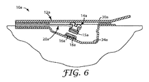
本発明の別の実施形態によるパッケージ化された歯科矯正アセンブリ10aを図6に示す。アセンブリ10aは、容器12a、装具14a、第1接着剤15a、剥離面16a、第2接着剤18a及び伸長した支持体20aを含む。以下に説明する以外は、アセンブリ10aはアセンブリ10と実質的に同一であり、そのため、一般的な外観の説明を繰り返す必要はない。
A packaged
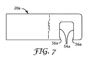
図6に示すように、容器12aが閉じられているとき、支持体20aは一般に平面的形状を有する。支持体20a単独の平面図を図7に示す。支持体20aの外側自由端は、2か所の縁部、すなわち、互いに間隙を介し、開口部を提示するアーム54aを含む。任意に、アーム54aの片方又は両方に小突出部56aを含めることで、アーム54a間の開口部、すなわち空隙に、装具14aを取り外し可能に保持するのに役立つ。
As shown in FIG. 6, when the
支持体20aは弾性を有し、復元力を有する。容器12aが開いている間、支持体20aは弛緩し、外側自由端が上方向に揺動して回転するように動き、アーム54aにより、容器12aの底部24aから離れる方向へ、第1接着剤15aと共に装具14aを移動する。容器12aが開き、支持体20aが弛緩すると、支持体20aは、好ましくは、アーム54aが容器12aのフランジより上方に間隔をあけて配置されるような形状を有する。
The
任意に、容器12aの底部24aは、容器12aのフランジ及び支持体20aの長手方向軸に対して傾斜した方向へ広がり、容器12aが閉じるとき、剥離面16aは第1接着剤15aに面するが、間隔をあけた関係で底部24aに広がる。容器12aのカバー30aが開くと、装具14について上述したように、ピンセット又はその他手用器具で、装具14aの側面を把持することができる。
Optionally, the bottom 24a of the
歯科医が第1接着剤15aへの第2接着剤18aの追加を選択する場合、歯科医は、装具14aを支持体20aと共に、第1接着剤15aが第2接着剤18aに接触するまで下向きに押し下げる。次いで、第2接着剤18aを第1接着剤15aへ移す。次に、装具14a上で圧力を解放することで、揺動により上方向に移動させる。
If the dentist chooses to add the second adhesive 18a to the
装具14a及び支持体20aのアーム54aが容器12aのフランジより上方位置に移動すると、アーム54aに沿って装具14aを動かすことにより、装具14aを支持体20aから取り外すことができる。装具14aが支持体20aから取り外されると、歯科医が患者の歯の表面に配置する状態となる。
When the
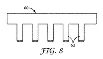
図8は、上述のアセンブリ10、10aを含む、本発明で使用可能なツール60の側面図である。ツール60は、間隔をあけて並ぶ、1列の細長い指部62を備える。一例として、図に示すように、5本の指部62が提供される。しかし、別の方法として、ツール60はより少ない又はより多い指部を有してもよい。
FIG. 8 is a side view of a
指部62間の間隔は、図2に示すキャリア38に収容されるときの容器12間の間隔とほぼ同じである。容器12のカバー30が開かれると、歯科医はツール60を用い、各装具14、14aの基部上の接着剤15、15aに、同時に接着剤18、18aを適用することができる。指部62を、各装具14、14aに同時に乗せ、各装具14、14aを下方向に、隣接する同量の第2接着剤18、18aに向かって動かす。次いで、ツール60を持ち上げ、指部62を装具14、14aから同時に外すことができ、そうすると、装具14、14aを個々に掴み、望みどおりに、患者の歯に配置することができる。
The interval between the
第1接着剤15、15aが第2接着剤18、18aとしっかりと接触するとき、任意に、装具14、14aの顔面側表面と、容器12、12a上部フランジとの間の距離に相当するような、指部62の長さが選択される。このような構造により、ユーザーが、チャンバ(例えば、チャンバ26)内に、極端に装具14、14aを押し込んだり、第1接着剤15、15a又は第2接着剤18、18aの形状を必要以上に変形させたりしないようにする。
When the
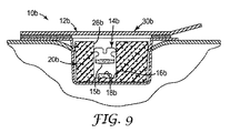
本発明の別の実施形態によるパッケージ化された歯科矯正アセンブリ10bを図9に示す。アセンブリ10bは、容器12b、装具14b、第1接着剤15b、剥離面16b、第2接着剤18b及び支持体20bを含む。上で説明した実施形態と同様に、第1接着剤15aは、好ましくは製造者により装具基部14bに適用される。カバー30bは、カバー30、30aと同様にチャンバ26bの開口部に広がり、図9には閉じた位置で示す。
A packaged
この実施形態では、支持体20bは、装具14bを取り外し可能なように収容する空洞を有する、圧縮性発泡体材料の部分を含む。空洞の底部において、支持体20bの中央上方向き表面は剥離面16bを含む。空洞の内部寸法は、第1接着剤15bが第2接着剤18bから通常離れた状態となるように、発泡体部材は、装具14bを宙吊りで支え、保持できるよう選択される。1つの選択肢として、発泡体部材中の空洞は、手用器具、例えば1本のピンセットをより容易に操作し、装具14bの近位側及び遠位側を把持する位置に入れられるように、装具14bの近位側及び遠位側に沿って広がる、垂直方向に伸びる凹部を含む。別の選択肢として、支持体20bの高さを図9に示す高さよりも低くし、装具14bの顔面側表面を、当初は支持体20bの上端より上部に位置させ(図10の装具14cの方向とほぼ同じ)装具14bの把持を容易にする。
In this embodiment, the
1つの選択肢として、第2接着剤18bの使用が望まれない場合に、装具14bを支持体20bの空洞から持ち上げ、チャンバ26bから取り出すことができる。しかし、第2接着剤18bの使用が望まれる場合は、歯科医は、装具14bを、第1接着剤15bが第2接着剤18bに接触するまで、下向き方向に移動させる。いったん接触すると、装具14bは第1接着剤15b及び第2接着剤18bの少なくとも一部と共に、空洞から持ち上げられチャンバ26bから取り出される。好ましくは、空洞に面する支持体20bの内壁は、装具14bがアセンブリ10bの運搬及び取り扱い中、安定かつ宙吊りで維持できるように十分な力を装具14bにかけるが、必要以上の力を入れずに装具14bを支持体20bから持ち上げ取り出せるように構成される。
As an option, if the use of the
歯科矯正アセンブリ10bのその他の態様は、上述のアセンブリ10、10aの態様と類似している。
Other aspects of the
本発明の別の実施形態によるパッケージ化された歯科矯正アセンブリ10cを図10に示す。アセンブリ10cは、容器12c、装具14c、第1接着剤15c、剥離面16c、第2接着剤18c、及び支持体20cを含む。更に、アセンブリ10cは、装具14cの「縦」チャネル(すなわち、装具14cの患者の歯への接着後に装具14cを見る場合に考慮される、咬合側−歯肉側方向に、装具14cの結合ウィング間を間隔をあけて伸びるチャネル)に取り外しができるように収容される位置決め部材21cを備える。好適な位置決め部材21cの例として、接着処置中、歯科医による歯の長手方向軸への装具14cの整列を助けるために提供される、長軸指標が挙げられる。
A packaged
図10に示すように、支持体20cは、剥離面16cを含む上方向き表面を有する中央部空洞を含む。支持体20cの上部は、図10に例示するように容器12cが閉じられるとき、位置決め部材21cの底縁部を取り外しができるように収容する1対の溝(図示せず)を含む。容器12cが閉じられるとき、アセンブリ10cの運搬及び取扱中に、装具14cが必要以上に押されたり、他の動きを受けたりしないように、好ましくは、位置決め部材21cは、支持体20cの上面とカバー30cの下面との間に挟まれる。好ましくは位置決め部材21cは、肩状部(図に示すような)、又はその他の指示記号若しくは構造を含み、これにより、接着処置中、歯科医が装具14cを正しい位置に、患者の歯の咬合側先端部から予め定められた距離で配置しやすくなる。
As shown in FIG. 10, the
接着処置中に歯科医が第2接着剤18cの使用を選択しない場合、カバー30cが開けられた直後に、装具14cを容器12cから取り出すことができる。この目的を達成するために、装具14cの側部をピンセットなどの手用器具で把持してもよい。別の選択肢として、歯科医は、装具14cの操作のため、位置決め部材21cの側部を把持することを選択してもよい。
If the dentist does not choose to use the second adhesive 18c during the bonding procedure, the appliance 14c can be removed from the
あるいは、歯科医が第1接着剤15cへの第2接着剤18cの一部又は全部の追加を選択した場合、装具14c又は位置決め部材21cの上部を、長軸指標21cの底縁部が支持体20cを圧縮するように押すことにより、装具14cを図10の下向き方向に移動させる。装具14cが下向き方向に連続的に移動することで、第1接着剤15cが第2接着剤18cと接触する。次いで、患者の歯に接着するため、装具14cを容器12cから持ち上げることができる。歯科矯正アセンブリ10cのその他の態様は、上述のアセンブリ10、10a、及び10bの対応する態様と類似している。
Alternatively, when the dentist chooses to add part or all of the second adhesive 18c to the first adhesive 15c, the upper part of the appliance 14c or the
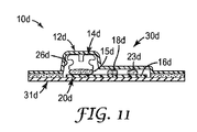
本発明の更なる実施形態によるパッケージ化された歯科矯正アセンブリ10dを図11に示す。アセンブリ10dは、容器12d、歯科矯正装具14d、装具14dの基部に広がる第1接着剤15d、剥離面16d、第2接着剤18d及び支持体20dを含む。アセンブリ10dは更に、容器12dのチャンバ26内で、第1接着剤15d及び第2接着剤18dから間隔をあけて配置される第3接着剤23dを含む。
A packaged
図11に示す実施形態では、容器12dは、支持体20dの外縁部に取り外し可能に固定される下方周辺部のフランジを有する、ドーム形のカバー30dを備える。剥離面16dは、容器12dが閉じられるとき、チャンバ26d内に包含される。しかし別の方法として、カバー30dのフランジが、支持体20dの外縁部の代わりに剥離面16dの外縁部に取り外し可能に固定されるように、剥離面16dの領域が支持体20dの上面領域と同一の広がりを有してもよい。好ましくは、カバー30dの形状は、チャンバ26d内に余分な空隙ができないように選択される。図には示していないが、容器12dは、支持体20dの両サイドを覆う遮光フィルム部分などの、遮光フィルム部も含んでもよい。
In the embodiment shown in FIG. 11, the
第1接着剤15dは、製造者により装具14dの基部に予め塗布されており、剥離面16dに接している。第2接着剤18d及び第3接着剤23dは、直接剥離面16dに塗布されている。接着剤18d、23dは双方とも、容器12dが閉じているとき、当初は装具14d及び第1接着剤15dから間隔をあけて配置される。カバー30dを開くと、歯科医は、第1接着剤15dのみを用いて装具14dを患者の歯に接着することを選択できるし、又はその代りに、装具14dを患者の歯に接着する前に、接着剤18d、23dのどちらか又は両方を、接着剤15dに追加することを選択できる。
The
1つの例として、容器12dが開かれた後、歯科医は装具14dの近位側及び遠位側を把持し、第2接着剤18dの全部又は一部をすくい取るために、装具14dを第2接着剤18dの方へ移動させてもよい。第3接着剤23dの使用も望む場合は、歯科医は、更に第3接着剤23dの全部又は一部もすくい上げ取られ、接着剤15d、18dに追加されるまで、装具14dを第3接着剤23dの方へ動かし続けてもよい。この例では、各接着剤18d、23dは、第1接着剤15dの重量の20%に等しい既知の量で存在してもよい。結果として、所望の場合、歯科医は、装具14d上の接着剤の総量が、接着剤18dをすくい取ることで約20%、又は第2接着剤18d及び第3接着剤23dの両方をすくい取ることで約40%増加することを選択できる。
As one example, after the
他の選択肢として、アセンブリ10dは、周知量の接着剤(接着剤18dなど)を1つだけ、又は周知量の接着剤(例えば、接着剤18d及び23dと類似)を3つ以上余分に含んでもよい。アセンブリ10dのその他の態様は、上述のアセンブリ10、10a、10b、及び10cの対応する態様と類似している。
As another option,
本発明の更に別の実施形態によるパッケージ化された歯科矯正アセンブリ10eを図12に示す。アセンブリ10eは、容器12e、装具14e、及び装具14eの基部に広がる第1接着剤15eを含む。この実施形態では、第1接着剤15eは支持体20eの上面である剥離面16eと接触している。第2接着剤18eは、支持体20eの底部と、容器12eの底部24eの上面との間の層に広がる。カバー30eは、所望の際に装具14eに接触できるように、閉鎖位置から開放位置へと移動可能である。
A packaged orthodontic assembly 10e according to yet another embodiment of the invention is shown in FIG. The assembly 10e includes a container 12e, an
図12に示す実施形態では、歯科医は、第1接着剤15eを用いて、患者の歯に装具14eを接着することを選択することができる。しかし、第2接着剤18eの使用も望まれた場合、装具14eを剥離面16eから持ち上げた後、支持体20eを容器12eから取り外すことができる。次いで、装具14eを操作し、第1接着剤15eを第2接着剤18eに接触させることにより、又は、手用器具(スパチュラなど)を用いて第2接着剤18eの全部又は一部をすくい取り、それを第1接着剤15eに塗布することにより、第2接着剤18eを第1接着剤15eに追加できる。
In the embodiment shown in FIG. 12, the dentist can choose to use the first adhesive 15e to adhere the
本発明の更に別の実施形態に従って構成されたパッケージ化された歯科矯正アセンブリ10fを図13に示す。アセンブリ10fは、カバー30fの容器12f、装具14f、及び装具14fの基部に広がる第1接着剤15fを含む。第2接着剤18fは、容器12f内のチャンバの底部24fに付着される、剥離面16fの一部に乗っている。あるいは、チャンバの底部24fは、コーティングされ、又はそれ以外に別の方法で製造され、第2接着剤18fに好適な剥離面を提供することもあり得る。
A packaged
支持体20fは、第1接着剤15fに適合する材料で作られる。任意に、支持体20fは、可撓性、剛性、又は半剛性の発泡体材料を含む。また、支持体20fは、エラストマー材を含んでもよい。図示した実施形態では、生じる抗力が、支持体20fを容器12f内の定位置に保持する働きをするように、支持体20fは、チャンバの内壁に対して圧縮状態の大きさである。あるいは、又はこれに加えて、容器12fは、支持体20fの外辺部を収容する内側の出っ張り、棚状部分、切り込み、又はその他の構造を備える場合もある。
The support 20f is made of a material compatible with the
装具14fは、支持体20fの切れ目又は開口部に収容される。容器12fが開くと、歯科医は装具14fの側部、例えば、近位側及び遠位側を把持することができる。歯科医は、所望の際に装具14fを下方向に押し、第2接着剤18fを第1接着剤15fに加えることを選択できる。支持体20fが可撓性材料で作られる場合、第2接着剤18fが第1接着剤15fに加えられるとき、支持体20fは曲がって装具14fに接触し続けることができる。あるいは、支持体20fがより剛性の材料で作られる場合、装具14fを、支持体20fの切れ目又は開口部を通って押して、第2接着剤18fに接触するようにし、次いで、支持体20fが図13に示す配置に本質的にとどまるようにしながら、装具14fを切れ目又は開口部を通って戻すように引いて取り外す。
The appliance 14f is accommodated in the cut or opening of the support 20f. When the container 12f is opened, the dentist can grip the side of the appliance 14f, for example, the proximal side and the distal side. The dentist can choose to push the appliance 14f downward and add the second adhesive 18f to the
更に別の選択肢として、支持体20fの1か所以上の側部を、隣接する容器12fの側壁から間隔をあけて配置して、支持体20f内の開口部を、図7に示す支持体20aの開口部と同様にする。1つの例として、支持体20fを容器12fのチャンバに広がる棒又はストリップの形状で構成でき、支持体20fは、装具14fをチャンバ内に宙吊りで支える切り込みを含んでもよい。所望の際は、装具14fを横方向(すなわち、水平方向に切り込みの開口部に向かって)にスライドさせることにより、装具14fを支持体20fから取り外してもよい。この例では、第2接着剤18fは、宙吊りの装具14fの真下の底部24fに位置するか、又は宙吊りの装具14fから横にずらしてもよい。アセンブリ10fのその他の態様及び選択肢は、アセンブリ10〜10eに関して上述した態様及び選択肢と類似している。
As yet another option, one or more sides of the support 20f are spaced from the side wall of the adjacent container 12f, and the opening in the support 20f is shown in FIG. The same as the opening. As one example, the support 20f may be configured in the form of a bar or strip that extends into the chamber of the container 12f, and the support 20f may include a notch that supports the appliance 14f suspended in the chamber. If desired, the appliance 14f may be removed from the support 20f by sliding the appliance 14f laterally (i.e., horizontally towards the cut opening). In this example, the second adhesive 18f may be located at the bottom 24f directly below the hanging device 14f or may be shifted laterally from the hanging device 14f. Other aspects and options of
上記の説明は、本発明の様々な態様の例示を意図したものであり、様々なバリエーションが可能である。例えば、図1〜4、6〜7、9〜10、及び12〜13に示す実施形態は、図11に示す容器12dと類似する容器を包含する場合もある。別の例として、追加量の上述の接着剤モノマー又は硬化剤を、容器内、例えば、発泡体製の支持体の孔の中に提供することができる。装具用の支持体は、図示したもの以外の形状を取ってもよい。更に、本明細書で説明したコンセプトを、インダイレクトボンディング用トレーに供給される装具と関連して用いてもよい。
The above descriptions are intended to illustrate various aspects of the invention, and various variations are possible. For example, the embodiments shown in FIGS. 1-4, 6-7, 9-10, and 12-13 may include containers similar to the
なお、上述の接着剤はいずれも、例えば、公開済みの米国特許出願第2005/0136370号(ブレナン(Brennan)ら)で説明される多層接着剤として提供してもよい。1つの例として、接着促進剤を含有する接着剤の薄層が装具基部に隣接し、第2層(すなわち、第1層に直接隣接する層)が、特定の粘度、処理特性又は強度特性を選択した接着剤を含んでもよい。 It should be noted that any of the above-described adhesives may be provided as, for example, a multilayer adhesive described in published US Patent Application No. 2005/0136370 (Brennan et al.). As one example, a thin layer of adhesive containing an adhesion promoter is adjacent to the brace base and a second layer (ie, a layer directly adjacent to the first layer) has a particular viscosity, processing characteristic or strength characteristic. It may include a selected adhesive.
多くの他のバリエーションもまた可能である。したがって、本発明は、上に詳細に記載した、現時点で好ましい実施形態に限定されるのではなく、むしろ、先の特許請求の公正な範囲及びその等価物によってのみ限定されるとみなされるべきである。 Many other variations are also possible. Accordingly, the invention is not to be limited to the presently preferred embodiments described in detail above, but rather should be considered limited only by the fair scope of the preceding claims and their equivalents. is there.
Claims (32)
前記チャンバ内に収容される歯科矯正装具であって、基部を含む装具と、
前記装具の前記基部に広がる第1歯科矯正接着剤と、
前記チャンバ内の剥離面と、
前記剥離面に受けられる第2歯科矯正接着剤と、
を含み、
前記第2歯科矯正接着剤が前記チャンバ内で前記第1歯科矯正接着剤から間隔をあけて配置される、パッケージ化された歯科矯正アセンブリ。 A container comprising a chamber;
An orthodontic appliance housed in the chamber, the appliance including a base;
A first orthodontic adhesive extending to the base of the appliance;
A release surface in the chamber;
A second orthodontic adhesive received on the release surface;
Including
A packaged orthodontic assembly, wherein the second orthodontic adhesive is spaced from the first orthodontic adhesive in the chamber.
チャンバを有する容器に一定量の第2歯科矯正接着剤を配置することと、
前記第1歯科矯正接着剤が前記第2歯科矯正接着剤から間隔をあけるように、前記チャンバ内に前記歯科矯正装具を保持することと、
を含む、歯科矯正装具のパッケージ化方法。 Providing an orthodontic appliance and a first orthodontic adhesive extending to a base of the appliance;
Placing a quantity of a second orthodontic adhesive in a container having a chamber;
Holding the orthodontic appliance in the chamber such that the first orthodontic adhesive is spaced from the second orthodontic adhesive;
A method for packaging orthodontic appliances, comprising:
容器のチャンバ内に前記歯科矯正装具を保持することと、
前記チャンバ内に第2歯科矯正接着剤を配置することと、
前記容器のカバーを閉じることと、
続いて前記カバーを開け前記装具を露出することと、
前記第1接着剤を前記第2接着剤に接触する状態にするために、前記チャンバ内の前記装具及び前記第2歯科矯正接着剤を相対的に移動させることと、
を含む、歯科矯正装具への歯科矯正接着剤の塗布方法。 Providing an orthodontic appliance and a first orthodontic adhesive extending to a base of the appliance;
Holding the orthodontic appliance in a chamber of a container;
Placing a second orthodontic adhesive in the chamber;
Closing the cover of the container;
Subsequently opening the cover to expose the brace;
Relatively moving the appliance and the second orthodontic adhesive in the chamber to bring the first adhesive into contact with the second adhesive;
A method of applying an orthodontic adhesive to an orthodontic appliance, comprising:
Applications Claiming Priority (2)
| Application Number | Priority Date | Filing Date | Title |
|---|---|---|---|
| US11/750,437 US7726470B2 (en) | 2007-05-18 | 2007-05-18 | Packaged orthodontic appliance and adhesive material |
| PCT/US2008/059697 WO2008144123A1 (en) | 2007-05-18 | 2008-04-09 | Packaged orthodontic appliance and adhesive material |
Publications (2)
| Publication Number | Publication Date |
|---|---|
| JP2010527652A true JP2010527652A (en) | 2010-08-19 |
| JP2010527652A5 JP2010527652A5 (en) | 2011-05-26 |
Family
ID=39590483
Family Applications (1)
| Application Number | Title | Priority Date | Filing Date |
|---|---|---|---|
| JP2010508473A Withdrawn JP2010527652A (en) | 2007-05-18 | 2008-04-09 | Packaged orthodontic appliances and adhesives |
Country Status (4)
| Country | Link |
|---|---|
| US (1) | US7726470B2 (en) |
| EP (1) | EP2155102A1 (en) |
| JP (1) | JP2010527652A (en) |
| WO (1) | WO2008144123A1 (en) |
Cited By (4)
| Publication number | Priority date | Publication date | Assignee | Title |
|---|---|---|---|---|
| KR20130085019A (en) * | 2012-01-18 | 2013-07-26 | 가부시키가이샤 지씨 | Package container for orthodontic mouthpiece |
| JP2015514552A (en) * | 2012-04-27 | 2015-05-21 | スリーエム イノベイティブ プロパティズ カンパニー | Container for orthodontic appliance |
| JP2016514998A (en) * | 2013-03-14 | 2016-05-26 | ティーピー・オーソドンティクス・インコーポレーテッドTp Orthodontics Incorporated | Packaging container for bracket with adhesive |
| CN107427351A (en) * | 2015-03-10 | 2017-12-01 | 3M创新有限公司 | Encapsulation orthodontic component with angled supporting construction |
Families Citing this family (28)
| Publication number | Priority date | Publication date | Assignee | Title |
|---|---|---|---|---|
| EP2364126A1 (en) * | 2008-11-14 | 2011-09-14 | 3M Innovative Properties Company | Dispensing assemblies, arrays and systems for dental articles |
| US8551457B2 (en) | 2008-11-25 | 2013-10-08 | The Procter & Gamble Company | Oral care compositions comprising spherical fused silica |
| WO2010068442A1 (en) * | 2008-11-25 | 2010-06-17 | The Procter & Gamble Company | Improved cleaning oral care compositions |
| IN2012DN02327A (en) * | 2009-09-18 | 2015-08-21 | Cao Group Inc | |
| US20110166555A1 (en) * | 2009-09-30 | 2011-07-07 | Jianbo Zhou | Carrier for an insertable medical device, insertion tools, methods of use, and kits |
| US8875873B2 (en) | 2010-06-02 | 2014-11-04 | 3M Innovative Properties Company | Packaged orthodontic assembly with retaining member |
| US20120150122A1 (en) * | 2010-12-10 | 2012-06-14 | Beverly Harper | Protective bandaging for point of insertion of shunt tubing |
| EP2874561B1 (en) | 2012-07-23 | 2020-08-26 | 3M Innovative Properties Company | Self-ligating orthodontic bracket |
| WO2014070920A1 (en) | 2012-10-30 | 2014-05-08 | University Of Southern California | Orthodontic appliance with snap fitted, non-sliding archwire |
| CN104768520B (en) | 2012-11-05 | 2017-06-13 | 宝洁公司 | The precipitated silica of heat treatment |
| US9113984B2 (en) | 2013-07-18 | 2015-08-25 | Tp Orthodontics, Inc. | Pod for shipping prepasted orthodontic appliances |
| WO2015105945A2 (en) * | 2014-01-09 | 2015-07-16 | Rhondium Holdings Limited | A dental restorative device and method of using the same |
| AU2015231895B2 (en) * | 2014-03-20 | 2019-05-30 | Ultradent Products, Inc. | Packaging systems including sacrificial composition |
| DE102014111629A1 (en) | 2014-08-14 | 2016-02-18 | Geting Solutions Gmbh | Material for covering adhesive surfaces |
| US9539074B2 (en) * | 2014-10-07 | 2017-01-10 | PDB, Patent & Business Development AG | Package for an orthodontic bracket |
| EP3328315A4 (en) * | 2015-07-24 | 2019-04-10 | DENTSPLY SIRONA Inc. | Package for orthodontic brackets |
| EP3478215B1 (en) | 2016-06-30 | 2022-07-27 | 3M Innovative Properties Company | Self-ligating orthodontic bracket |
| US10828133B2 (en) | 2016-12-02 | 2020-11-10 | Swift Health Systems Inc. | Indirect orthodontic bonding systems and methods for bracket placement |
| US10881489B2 (en) | 2017-01-31 | 2021-01-05 | Swift Health Systems Inc. | Hybrid orthodontic archwires |
| US11612458B1 (en) | 2017-03-31 | 2023-03-28 | Swift Health Systems Inc. | Method of tongue preconditioning in preparation for lingual orthodontic treatment |
| CN114129289A (en) | 2017-04-21 | 2022-03-04 | 斯威夫特健康系统有限公司 | Indirect-bonded tray, non-slip orthodontic appliance and registration system using the same |
| US10779910B2 (en) | 2017-09-25 | 2020-09-22 | Ormco Corporation | Orthodontic bracket axis indicator |
| EP3745993B1 (en) | 2018-02-02 | 2022-10-12 | 3M Innovative Properties Company | Ceramic self-ligating bracket with high labial pull strength |
| WO2019175726A1 (en) | 2018-03-12 | 2019-09-19 | 3M Innovative Properties Company | Packaged orthodontic appliances |
| EP3962403A4 (en) | 2019-05-02 | 2023-05-17 | World Class Technology Corporation | Orthodontic bracket with a biased ligating member |
| WO2022144843A1 (en) * | 2020-12-30 | 2022-07-07 | 3M Innovative Properties Company | Bondable orthodontic assemblies and methods for bonding |
| WO2022149084A1 (en) | 2021-01-08 | 2022-07-14 | 3M Innovative Properties Company | Prescription attachments for use in each phase of combination orthodontic treatment |
| WO2024052875A1 (en) | 2022-09-09 | 2024-03-14 | Solventum Intellectual Properties Company | Transfer apparatus for orthodontic appliances and related methods of manufacturing |
Family Cites Families (35)
| Publication number | Priority date | Publication date | Assignee | Title |
|---|---|---|---|---|
| US3814717A (en) * | 1970-12-04 | 1974-06-04 | Dental Materials Section Labor | Poly(carboxylic acid)-fluoroalumino-silicate glass surgical cement |
| US5015180A (en) * | 1989-03-01 | 1991-05-14 | Minnesota Mining And Manufacturing Company | Dental article containing light-curable paste |
| US4978007A (en) * | 1989-05-10 | 1990-12-18 | Minnesota Mining And Manufacturing Company | Packaging curable materials |
| US5348154A (en) * | 1989-05-10 | 1994-09-20 | Minnesota Mining And Manufacturing Company | Packaging curable materials |
| US5152917B1 (en) * | 1991-02-06 | 1998-01-13 | Minnesota Mining & Mfg | Structured abrasive article |
| US5354199A (en) * | 1991-08-02 | 1994-10-11 | Minnesota Mining And Manufacturing Company | Adhesive for packaged orthodontic appliance |
| EP0596920B1 (en) * | 1991-08-02 | 1996-11-13 | Minnesota Mining And Manufacturing Company | Packaged dental article |
| US5549962A (en) * | 1993-06-30 | 1996-08-27 | Minnesota Mining And Manufacturing Company | Precisely shaped particles and method of making the same |
| US5538129A (en) * | 1995-03-21 | 1996-07-23 | Minnesota Mining And Manufacturing Company | Package for adhesive precoated dental appliance |
| US5697780A (en) * | 1995-10-12 | 1997-12-16 | American Orthodontics Corporation | Orthodontic appliance kit and components |
| US6126922A (en) * | 1995-11-17 | 2000-10-03 | 3M Innovative Properties Company | Fluorid-releasing compositions and compositions with improved rheology |
| US6050815A (en) * | 1996-03-15 | 2000-04-18 | 3M Innovative Properties Company | Precoated dental cement |
| US5810582A (en) * | 1996-07-02 | 1998-09-22 | Doyle; Walter A. | Orthodontic bracket holding and placement apparatus |
| US5759028A (en) * | 1996-08-08 | 1998-06-02 | Gac International, Inc. | Orthodontic bonding system |
| US5827058A (en) * | 1997-10-08 | 1998-10-27 | Minnesota Mining & Manufacturing Co. | Carrier for supporting orthodontic brackets |
| US6331080B1 (en) * | 1998-07-15 | 2001-12-18 | 3M Innovative Properties Company | Optical fiber connector using colored photocurable adhesive |
| US5971754A (en) * | 1998-07-30 | 1999-10-26 | Sondhi; Anoop | Indirect bonding method and adhesive for orthodontic treatment |
| AU6050799A (en) | 1999-05-13 | 2000-12-05 | 3M Innovative Properties Company | Fluoride releasing orthodontic adhesive |
| US6183249B1 (en) * | 1999-07-29 | 2001-02-06 | 3M Innovative Properties Company | Release substrate for adhesive precoated orthodontic appliances |
| US6213767B1 (en) * | 1999-08-19 | 2001-04-10 | Ormco Corporation | Individual dose adhesive delivery and orthodontic appliance system |
| US6482003B2 (en) * | 1999-08-19 | 2002-11-19 | Ormco Corporation | Individual dose dental adhesive delivery system and method |
| US6444725B1 (en) * | 2000-01-21 | 2002-09-03 | 3M Innovative Properties Company | Color-changing dental compositions |
| US6528555B1 (en) * | 2000-10-12 | 2003-03-04 | 3M Innovative Properties Company | Adhesive for use in the oral environment having color-changing capabilities |
| US6513897B2 (en) * | 2000-12-29 | 2003-02-04 | 3M Innovative Properties Co. | Multiple resolution fluid applicator and method |
| US6843370B2 (en) * | 2001-06-20 | 2005-01-18 | American Orthodontics | Package for prepasted orthodontic bracket |
| US20030196914A1 (en) * | 2002-04-18 | 2003-10-23 | 3M Innovative Properties Company | Containers for photocurable materials |
| US6960079B2 (en) * | 2002-04-18 | 2005-11-01 | 3M Innovative Properties Company | Orthodontic adhesives and appliances including an adhesive on the base of the appliance |
| US6834761B1 (en) * | 2002-12-17 | 2004-12-28 | Tp Orthodontics, Inc. | Package for ready mountable bondable orthodontic appliances and method of making same |
| US7188421B2 (en) * | 2003-05-02 | 2007-03-13 | 3M Innovative Properties Company | Orthodontic appliances having a contoured bonding surface |
| WO2005009867A1 (en) * | 2003-07-15 | 2005-02-03 | 3M Innovative Properties Company | Paste composition storage device and method |
| EP2279722B1 (en) * | 2003-08-12 | 2013-05-01 | 3M Innovative Properties Company | Self-etching dental compositions and its use |
| US20050133384A1 (en) * | 2003-12-19 | 2005-06-23 | 3M Innovative Properties Company | Packaged orthodontic assembly with adhesive precoated appliances |
| US7381053B2 (en) * | 2004-04-10 | 2008-06-03 | American Orthodontics Corporation | Packaging system for pre-pasted orthodontic bracket |
| US7338282B2 (en) * | 2004-09-14 | 2008-03-04 | Ormco Corporation | Single patient package for dental appliances and methods of using |
| WO2006058162A2 (en) | 2004-11-23 | 2006-06-01 | Ormco Corporation | Orthodontic brackets having different adhesives and methods and appliances therewith |
-
2007
- 2007-05-18 US US11/750,437 patent/US7726470B2/en not_active Expired - Fee Related
-
2008
- 2008-04-09 JP JP2010508473A patent/JP2010527652A/en not_active Withdrawn
- 2008-04-09 EP EP08745330A patent/EP2155102A1/en not_active Withdrawn
- 2008-04-09 WO PCT/US2008/059697 patent/WO2008144123A1/en active Application Filing
Cited By (6)
| Publication number | Priority date | Publication date | Assignee | Title |
|---|---|---|---|---|
| KR20130085019A (en) * | 2012-01-18 | 2013-07-26 | 가부시키가이샤 지씨 | Package container for orthodontic mouthpiece |
| KR101970018B1 (en) | 2012-01-18 | 2019-04-17 | 가부시키가이샤 지씨 | Package container for orthodontic mouthpiece |
| JP2015514552A (en) * | 2012-04-27 | 2015-05-21 | スリーエム イノベイティブ プロパティズ カンパニー | Container for orthodontic appliance |
| JP2016514998A (en) * | 2013-03-14 | 2016-05-26 | ティーピー・オーソドンティクス・インコーポレーテッドTp Orthodontics Incorporated | Packaging container for bracket with adhesive |
| CN107427351A (en) * | 2015-03-10 | 2017-12-01 | 3M创新有限公司 | Encapsulation orthodontic component with angled supporting construction |
| CN107427351B (en) * | 2015-03-10 | 2020-08-18 | 3M创新有限公司 | Encapsulated orthodontic assembly with angled support structure |
Also Published As
| Publication number | Publication date |
|---|---|
| EP2155102A1 (en) | 2010-02-24 |
| WO2008144123A1 (en) | 2008-11-27 |
| US7726470B2 (en) | 2010-06-01 |
| US20080286710A1 (en) | 2008-11-20 |
Similar Documents
| Publication | Publication Date | Title |
|---|---|---|
| JP2010527652A (en) | Packaged orthodontic appliances and adhesives | |
| US7841464B2 (en) | Packaged orthodontic appliance with user-applied adhesive | |
| US7473096B2 (en) | Orthodontic adhesive dispensing assembly | |
| JP4440507B2 (en) | Peeling substrate for use in adhesive pre-coated orthodontic appliances | |
| JP4870677B2 (en) | Orthodontic method and apparatus for applying a composition to a patient's teeth | |
| US7364428B2 (en) | Orthodontic indirect bonding tray with moisture control | |
| EP2224872B1 (en) | Methods and apparatus for applying dental sealant to an orthodontic patient s teeth | |
| JP4406006B2 (en) | Indirect bonding method and apparatus for orthodontic appliances | |
| JP4950175B2 (en) | Indirect bonding for orthodontics with stop member to determine occlusal position | |
| JP5422081B2 (en) | Packaged orthodontic assembly with retaining member | |
| JP2006525076A (en) | Orthodontic appliances with mating surfaces that fit the contour | |
| JP2011041827A (en) | Apparatus for indirect bonding of orthodontic appliance and method of making the same | |
| JP2011505973A (en) | Orthodontic articles having partially cured compositions and methods of use and manufacture thereof | |
| US5759028A (en) | Orthodontic bonding system | |
| US8021146B2 (en) | Apparatus and methods for controlling moisture during orthodontic indirect bonding procedures |
Legal Events
| Date | Code | Title | Description |
|---|---|---|---|
| A521 | Written amendment |
Free format text: JAPANESE INTERMEDIATE CODE: A523 Effective date: 20110331 |
|
| A621 | Written request for application examination |
Free format text: JAPANESE INTERMEDIATE CODE: A621 Effective date: 20110331 |
|
| A761 | Written withdrawal of application |
Free format text: JAPANESE INTERMEDIATE CODE: A761 Effective date: 20110727 |