JP2010525375A - System for projecting a three-dimensional image on a two-dimensional screen and corresponding method - Google Patents
System for projecting a three-dimensional image on a two-dimensional screen and corresponding method Download PDFInfo
- Publication number
- JP2010525375A JP2010525375A JP2009553184A JP2009553184A JP2010525375A JP 2010525375 A JP2010525375 A JP 2010525375A JP 2009553184 A JP2009553184 A JP 2009553184A JP 2009553184 A JP2009553184 A JP 2009553184A JP 2010525375 A JP2010525375 A JP 2010525375A
- Authority
- JP
- Japan
- Prior art keywords
- image
- screen
- point
- observer
- projection
- Prior art date
- Legal status (The legal status is an assumption and is not a legal conclusion. Google has not performed a legal analysis and makes no representation as to the accuracy of the status listed.)
- Pending
Links
Images


Classifications
-
- H—ELECTRICITY
- H04—ELECTRIC COMMUNICATION TECHNIQUE
- H04N—PICTORIAL COMMUNICATION, e.g. TELEVISION
- H04N13/00—Stereoscopic video systems; Multi-view video systems; Details thereof
- H04N13/30—Image reproducers
- H04N13/366—Image reproducers using viewer tracking
-
- H—ELECTRICITY
- H04—ELECTRIC COMMUNICATION TECHNIQUE
- H04N—PICTORIAL COMMUNICATION, e.g. TELEVISION
- H04N13/00—Stereoscopic video systems; Multi-view video systems; Details thereof
- H04N13/30—Image reproducers
- H04N13/363—Image reproducers using image projection screens
Landscapes
- Engineering & Computer Science (AREA)
- Multimedia (AREA)
- Signal Processing (AREA)
- Transforming Electric Information Into Light Information (AREA)
- Projection Apparatus (AREA)
- Stereoscopic And Panoramic Photography (AREA)
- Image Processing (AREA)
Abstract
本発明は、2次元スクリーン(2)上に3次元画像を映写するための方法に関し、スクリーン形状に応じて且つ固定基準点に関して、その映写前に画像を変形可能な各画像用の静的補正モジュール(17)を有する。システムはさらに、スクリーンを見ている選択されたオブザーバの位置をリアルタイムで検知可能なセンサ(7)と、静的補正モジュールの上流に接続された、前記オブザーバの位置、基準点の位置、及びスクリーン形状に基づいて、前記基準点に対するオブザーバの動きによって各画像に生成される歪みをリアルタイムで自動的に補正することが可能な動的補正モジュール(11)とを有する。
【選択図】 図1The present invention relates to a method for projecting a three-dimensional image on a two-dimensional screen (2), with respect to the screen shape and with respect to a fixed reference point, a static correction for each image that can be transformed before the projection. It has a module (17). The system further includes a sensor (7) capable of detecting in real time the position of the selected observer looking at the screen, and the position of the observer, the position of the reference point, and the screen connected upstream of the static correction module. And a dynamic correction module (11) capable of automatically correcting, in real time, distortion generated in each image by the movement of the observer with respect to the reference point based on the shape.
[Selection] Figure 1
Description
本発明は概して、2次元スクリーン上への3次元合成画像の映写に関する。これらの映写システムはとりわけシミュレーションシステム(例えば、運転シミュレーションシステム)やバーチャルリアリティシステムで用いられる。 The present invention generally relates to the projection of a three-dimensional composite image on a two-dimensional screen. These projection systems are used in particular in simulation systems (eg, driving simulation systems) and virtual reality systems.
実際には、シミュレーションやバーチャルリアリティシステムは、コンピュータで計算された3次元合成画像を表示するためにパノラマ映写スクリーンを利用する。目−スクリーン間距離の変化を最小限としながらユーザにとって有効な視野を広げるため、好ましくは湾曲したスクリーンが用いられる。 In practice, simulations and virtual reality systems use panoramic projection screens to display computer-generated 3D composite images. A curved screen is preferably used to expand the effective field of view for the user while minimizing changes in the eye-screen distance.
湾曲スクリーンへの映写は必然的に、画像の幾何学的変形を生じる。しかしながらこの変形は、静的歪み補正モジュールを用いた逆変形を実行することで容易に相殺できる。こうしてオブザーバは正しい遠近感で3次元のシーンを見ることができる。 Projection onto a curved screen necessarily results in geometric deformation of the image. However, this deformation can be easily canceled by performing reverse deformation using a static distortion correction module. In this way, the observer can see the 3D scene with the correct perspective.
ところが湾曲スクリーンに映写する現行のシステムは、単一の視点用に設計されている。すなわち、オブザーバが動くごとに彼の見ている画像が歪むことに繋がる。この歪みはスクリーンの湾曲によって生じたものとははっきり異なる。 However, current systems that project onto curved screens are designed for a single viewpoint. That is, every time the observer moves, the image he sees is distorted. This distortion is distinct from that caused by the curvature of the screen.
そして、多くの用途がオブザーバに動きを要求する。 And many uses require observers to move.
公知の映写システムは、湾曲スクリーンによって生じる歪みを相殺するために(上述の静的歪み補正)、画像の逆変形を実行するハードウェア又はソフトウェア手段を利用する。これらのハードウェア又はソフトウェア手段は、映写システムの幾何学的形状(映写機の光学的特性及びスクリーンの幾何学的形状)に応じてオペレータによって予めパラメータ化される。 Known projection systems utilize hardware or software means to perform the inverse deformation of the image in order to offset the distortion caused by the curved screen (static distortion correction as described above). These hardware or software means are pre-parameterized by the operator depending on the projection system geometry (projector optical properties and screen geometry).
しかしながら、オブザーバの動きによる歪みを避けるために一般的に採用される解決法は、映写システムが調整されているポイントに関して、その移動を制限する。 However, solutions that are commonly employed to avoid distortion due to observer movement limit their movement with respect to the point at which the projection system is being adjusted.
あるいは、3次元合成画像ジェネレータのレベルで、オブザーバの動きと関連した歪みについて画像補正計算を行うことも可能である。ただしこの解決法は、映写システムの幾何学的形状についての非常に包括的な知識を必要とし、実際には常に可能というわけではない。さらにこの解決法は、計算時間において比較的高価である。 Alternatively, it is also possible to perform image correction calculations for distortions associated with observer motion at the level of the 3D composite image generator. However, this solution requires a very comprehensive knowledge about the geometry of the projection system and is not always possible in practice. Furthermore, this solution is relatively expensive in computation time.
具体的には、公報US2006/0077355が、複数の映写機を用いたシステム用の歪み補正手段を開示している。この手段はスクリーン上に、そのスクリーンの形状による歪みを被ることなく連続的画像を得ることを可能とする。ただし補正パラメータのリアルタイムアップデートに対しては備えがない。 Specifically, publication US 2006/0077355 discloses distortion correction means for a system using a plurality of projectors. This measure makes it possible to obtain a continuous image on the screen without suffering distortion due to the shape of the screen. However, there is no provision for real-time update of correction parameters.
公報US2005/0140575は湾曲スクリーン上への画像の映写によって生じる歪みを補正する装置を記載している。この公報は、湾曲スクリーン上にそれらを正しく表示するために、単純且つ計算時間において安価な計算によって画像の逆変形を非常に迅速に生じせしめる方法を提案している。ただし変形のパラメータは静的である。それらは、他の形状にそれらを調整するのに、オペレータの介入を必要とする。したがって、オブザーバの視点に応じた変形を加えるためにこの公報に記載の装置を用いることは一切不可能である。 The publication US 2005/0140575 describes an apparatus for correcting distortion caused by projection of an image on a curved screen. This publication proposes a method for causing the image to be deformed very quickly by a simple and inexpensive calculation in order to display them correctly on a curved screen. However, the deformation parameters are static. They require operator intervention to adjust them to other shapes. Therefore, it is impossible to use the apparatus described in this publication in order to add a modification according to the observer's viewpoint.
公報US4714428は、映写機によって表示されるべき画像へと逆変形を加えることで歪みを補正する装置を開示している。しかしながら、提案の装置は、映写機によって処理された画像とスクリーンに実際に表示された画像の間の相関関係について詳しいことを必要とするため、比較的複雑である。さらにこの公報によって提案される補正装置は、単一のモジュールを用いて画像を補正するもので、これがすべての補正、すなわち「静的」変形の補正及び「動的」変形に関連しての補正の両方を扱う。この公報によって提案される装置はしたがって、比較的複雑で融通が利かない。 US Pat. No. 4,714,428 discloses an apparatus for correcting distortion by applying inverse deformation to an image to be displayed by a projector. However, the proposed device is relatively complex because it requires detailed information about the correlation between the image processed by the projector and the image actually displayed on the screen. Furthermore, the correction device proposed by this publication corrects an image using a single module, which is a correction for all corrections, ie corrections for “static” deformations and “dynamic” deformations. Handle both. The device proposed by this publication is therefore relatively complex and inflexible.
公報US5446834は、選択されたオブザーバの視点を考慮して、CRTタイプのスクリーン上に3次元のバーチャル画像を表示するのに用いられる方法を記載している。この方法は、そうしたスクリーンへの画像の表示で生じる歪み(湾曲及びスクリーンの光学的特性による歪み)の完璧且つ数学的なモデリングを必要とする。このモデリングは、比較的複雑な方法を暗示する。 The publication US 5446834 describes a method used to display a three-dimensional virtual image on a CRT type screen in view of the viewpoint of the selected observer. This method requires a complete and mathematical modeling of the distortion (distortion and distortion due to the optical properties of the screen) that occurs in the display of the image on such a screen. This modeling implies a relatively complex method.
公報JP2004/356989は、非平面スクリーンの幾何学的形状を考慮に入れるために、入力信号を幾何学的に補正するためのシステムを開示している。ただしこのシステムは、オブザーバの移動によって生じた歪みを補正することには一切使用できない。 Publication JP 2004/356969 discloses a system for geometrically correcting an input signal in order to take into account the geometry of the non-planar screen. However, this system cannot be used to correct any distortion caused by observer movement.
本発明はこれらの問題への解決法を提供することを目的とする。 The present invention aims to provide a solution to these problems.
本発明の目的の1つは、スクリーンの幾何学的形状(静的補正)及びスクリーン前面のオブザーバの移動(動的補正)によって生じる画像の歪みを、リアルタイムで単純に、オペレータの介入なしに補正しながら、3次元画像を2次元スクリーン上に映写するためのシステムを提案するものである。 One of the objects of the present invention is to correct image distortion caused by screen geometry (static correction) and observer movement in front of the screen (dynamic correction) simply and in real time without operator intervention. However, a system for projecting a three-dimensional image on a two-dimensional screen is proposed.
このため、本発明の第1の側面によれば、スクリーン形状に応じて且つ固定基準点に関して、その映写前に画像を変形可能な各画像用の静的補正モジュールを有する2次元スクリーン上に3次元画像を映写するためのシステムが提案される。 For this reason, according to the first aspect of the present invention, on the two-dimensional screen having a static correction module for each image, which can deform the image before projection, according to the screen shape and with respect to the fixed reference point. A system for projecting a dimensional image is proposed.
本発明のこの側面の一般的特徴によれば、前記システムはさらに、
・スクリーンを見ている選択されたオブザーバの位置をリアルタイムで検知可能なセンサと、
・静的補正モジュールの上流に接続された、前記オブザーバの位置、基準点の位置、及びスクリーン形状に基づいて、前記基準点に対するオブザーバの動きによって各画像に作りだされる歪みを自動的に且つリアルタイムで補正することが可能な動的補正モジュールと
を有する。
According to a general feature of this aspect of the invention, the system further comprises:
A sensor capable of detecting in real time the position of the selected observer looking at the screen;
Based on the position of the observer, the position of the reference point, and the screen shape connected upstream of the static correction module, the distortion created in each image by the movement of the observer with respect to the reference point is automatically and And a dynamic correction module capable of correcting in real time.
すなわち、本発明による画像映写システムは、静的補正モジュールに加えて、スクリーン前面のオブザーバの移動によって生じるさらなる歪みを補正可能な動的補正モジュールを有する。 That is, the image projection system according to the present invention has a dynamic correction module capable of correcting further distortion caused by the movement of the observer in front of the screen in addition to the static correction module.
このモジュールは、静的補正モジュールとははっきり異なるものである。このモジュールは、リアルタイムで且つオペレータによる介入とは無関係に動作するように設計されている。 This module is distinct from the static correction module. This module is designed to operate in real time and without operator intervention.
本発明の注目すべき利点は、とりわけ動的補正モジュールが、オブザーバの位置、基準点の位置、及びスクリーン形状に基づいて、オブザーバの動きによって生じる画像の歪みを単純に補正可能であるという事実のおかげで、比較的単純な動作を行うことである。 A notable advantage of the present invention is the fact that, among other things, the dynamic correction module can simply correct image distortion caused by observer movement based on observer position, reference point position, and screen shape. Thanks to the relatively simple operation.
さらに本発明は、映写中にオペレータの介入をもはや必要としないという利点を有する。実際、セットされるべきパラメータは、静的補正モジュールのものであって、それらは画像映写システムを始動させる前に一度だけセットされる。 Furthermore, the present invention has the advantage that it no longer requires operator intervention during the projection. In fact, the parameters to be set are those of the static correction module and they are set only once before starting the image projection system.
好ましくは、前記スクリーンは湾曲している。具体的には、スクリーンは、筒状、先細状、球面状、環状とできる。それは、(連続的又はサンプリングによる)分析的説明が行えるあらゆるタイプの表面形状を持ち得る。 Preferably, the screen is curved. Specifically, the screen can be cylindrical, tapered, spherical, or annular. It can have any type of surface shape that can be analytically explained (continuous or by sampling).
一実施例によれば、映写システムは、映写される画像の各点が空間での実際の位置に応じて配置されている、所定の形状に応じた平坦画像を計算可能な計算モジュールを有する画像ジェネレータをさらに備えることができる。 According to one embodiment, the projection system includes an image having a calculation module capable of calculating a flat image according to a predetermined shape, wherein each point of the image to be projected is arranged according to an actual position in space. A generator can be further provided.
さらに前記動的補正モジュールは、基準点からの、平坦画像上の対象点のスクリーン上への映写と、前記オブザーバの位置からの、他の対応する点のスクリーン上への映写が一致するように、計算された平坦画像の各点について、同平坦画像上に位置する他の点を決定することができる決定手段と、他の対応する点で平坦画像の各点を置換することができる置換手段とを有することができる。 Further, the dynamic correction module is arranged so that the projection of the target point on the flat image on the screen from the reference point matches the projection of the other corresponding point on the screen from the position of the observer. For each point of the calculated flat image, a determination unit that can determine another point located on the flat image, and a replacement unit that can replace each point of the flat image with another corresponding point Can have.
一実施例によれば、動的補正モジュールは、画像ジェネレータと静的補正モジュールの間で接続されている。 According to one embodiment, the dynamic correction module is connected between the image generator and the static correction module.
本発明の他の側面によれば、2次元スクリーン上に3次元画像を映写するための上述のシステムを有する運転シミュレーション機器が提案される。 According to another aspect of the present invention, a driving simulation apparatus is proposed having the above-described system for projecting a three-dimensional image on a two-dimensional screen.
本発明の他の側面によれば、スクリーン形状に応じて且つ基準点に関して、その映写前に各画像が変形される「静的」補正ステップを有する、2次元スクリーン上に3次元画像を映写するための方法が提案される。 According to another aspect of the present invention, a three-dimensional image is projected on a two-dimensional screen having a “static” correction step in which each image is deformed before projection, depending on the screen shape and with respect to a reference point. A method for this is proposed.
前記方法はさらに、スクリーンを見ている選択されたオブザーバの位置をリアルタイムで検知するためのステップと、前記基準点に対するオブザーバの動きによって各画像に作りだされる歪みを、前記オブザーバの位置、基準点の位置、及びスクリーン形状に基づいて補正する「動的」補正ステップを有する。 The method further includes the step of detecting in real time the position of the selected observer looking at the screen, and the distortion created in each image by the movement of the observer relative to the reference point, the position of the observer, the reference It has a “dynamic” correction step for correcting based on the position of the points and the screen shape.
一実施例によれば、好ましくは、スクリーンは湾曲している。 According to one embodiment, preferably the screen is curved.
一実施形態によれば、この方法は、映写される画像の各点がその空間での実際位置に応じて配置されている平坦画像を計算する画像生成ステップを有し、ここで「動的」補正ステップは、基準点からの、平坦画像の対象点のスクリーン上への映写と、前記オブザーバの位置からの、他の対応する点のスクリーン上への映写が一致するように、計算された平坦画像の各点について、同平坦画像上に位置する他の点を決定すること、及び他の対応する点で平坦画像の各点を置換することを含むことができる。 According to one embodiment, the method comprises an image generation step of calculating a flat image in which each point of the projected image is arranged according to its actual position in the space, where “dynamic” The correction step is performed by calculating the flatness so that the projection of the target point of the flat image on the screen from the reference point matches the projection of the other corresponding point on the screen from the position of the observer. For each point of the image, it can include determining other points located on the same flat image and replacing each point of the flat image with another corresponding point.
一実施形態によれば、「動的」補正ステップは、画像生成ステップの後で、且つ「静的」補正ステップの前に実行することができる。 According to one embodiment, the “dynamic” correction step can be performed after the image generation step and before the “static” correction step.
本発明の他の利点及び特徴は、一切限定的なものではない本発明の実施例及び実施の詳細な説明、及び添付の図面を学ぶことから明らかとなろう。
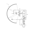
図1は、スクリーン2に3次元画像1を映写するためのシステムを非常に図式的に表している。この例では、スクリーン2は筒状である。画像はスクリーンの表面に映写される。ただし本発明は決して、筒状タイプの映写スクリーンに限られるものではない。
FIG. 1 very schematically represents a system for projecting a three-
実際、それは球面状、先細状、環状タイプ、あるいは(連続的又はサンプリングによる)分析的説明が行えるあらゆるタイプの表面形状とし得る。 In fact, it can be spherical, tapered, annular type, or any type of surface shape that can be analytically explained (continuously or by sampling).
映写システムはまた、ビデオ映写機、この場合は符号3、4、5の3台を有する。
The projection system also has three video projectors, in this case the
映写機3、4、5はいかなるタイプであってもよく、概ねスクリーン2をカバーする合成画像を作るように配置される。
The
単一のビデオ映写機が用いられてもよい。 A single video projector may be used.
オブザーバはスクリーン前面に置かれ、その位置は概ね彼の頭部の位置から、より詳しくは彼の目の位置から決定される。 The observer is placed in front of the screen, and its position is generally determined from the position of his head, more specifically from the position of his eyes.
このため、符号7の3次元位置センサがオブザーバの位置の検知に用いられる。 For this reason, a three-dimensional position sensor denoted by reference numeral 7 is used for detecting the position of the observer.
この例では具体的には、センサ7が、画像の3次元での表示に関連して視点を動的にアップデートするため、オブザーバの目の位置を3次元的に決定することを可能とする。目の位置は、固定基準点Rに対して示される。 Specifically, in this example, since the sensor 7 dynamically updates the viewpoint in relation to the display of the image in three dimensions, it is possible to determine the position of the observer's eyes in three dimensions. The eye position is shown relative to a fixed reference point R.
センサによって決定された位置は、コネクション9を介して画像ジェネレータ8へと伝達される。
The position determined by the sensor is transmitted to the
画像ジェネレータ8は、スクリーン2上に表示される3次元画像を、オブザーバの目の位置に応じて生成する。このために、画像ジェネレータ8は計算モジュール10を有するものであり、その機能は以下に詳述する。
画像ジェネレータ8によって生成された画像は、コネクション12を介して動的補正モジュール11へと伝達される。
The
The image generated by the
動的補正モジュール11はまた、コネクション13を介してセンサ7によって届けられたオブザーバの目の3次元位置も受け取る。
The dynamic correction module 11 also receives the three-dimensional position of the observer eye delivered by the sensor 7 via the
動的補正モジュール11の主要な機能は、符号6の所定の静的較正点に対するオブザーバの動きを相殺するために、画像ジェネレータ8によって生成された画像を変形することである。この変形は、現行のグラフィックス・カードで一般に利用可能ないわゆる「ピクセルシェーディング」技術を用いて加えることができる。この技術の主要なステップは、以下に詳述する。
The main function of the dynamic correction module 11 is to deform the image generated by the
具体的には、動的補正モジュールは、決定手段14と置換手段15を有するものであり、その機能は以下に詳述する。
Specifically, the dynamic correction module includes a
さらに動的補正モジュール11は、湾曲スクリーン2の形状を記憶可能なメモリ16を有する。
Further, the dynamic correction module 11 has a
動的補正モジュール11によって変形された画像は、次にコネクション18を介して静的補正モジュール17へと伝達される。
The image deformed by the dynamic correction module 11 is then transmitted to the
静的補正モジュール17は、湾曲スクリーン2の形状及び映写機3、4、5の光学的特性から生じた歪みを相殺するために、画像のさらなる変形を行う。
The
具体的には、静的歪み補正モジュール17は、概ねスクリーンの中央に来るように選ばれた(この位置はコネクション19を介して伝達される)符号6の所定の視点に対して正しい透視図をもたらすために、映写画像の変形を行う。この視点はまた、上述の動的歪み補正モジュール11によっても用いられる。この基準点はこのとき、コネクション20を介してモジュール11へと伝達される。
Specifically, the static
静的補正モジュール17は、映写前にオペレータによってセットされる。セッティングは一度だけで、映写中のオペレータのさらなる介入を必要としない。動的補正モジュール11は、オブザーバの目の位置に応じてリアルタイムで自動的に動作する。
The
最後に、静的補正モジュールは映写機3、4、5へと、映写されるべき画像をそれらに伝達するために、コネクション21を介して接続される。
Finally, the static correction module is connected to
ここで図2を参照すると、この図は、画像ジェネレータ8、動的補正モジュール11、及び静的補正モジュール17によって実施されるアルゴリズムをより詳細に記述している。
Reference is now made to FIG. 2, which describes in more detail the algorithm implemented by the
まず最初に、オブザーバの位置、とりわけ彼の目の位置が検知100される。次にこの位置に応じて、スクリーン200の上に表示される3次元合成画像が生成される。
First, the position of the observer, in particular his eye position, is detected 100. Next, a three-dimensional composite image displayed on the
画像生成200はとりわけ、平坦画像の計算201を含む。計算201は、図1の符号10の計算モジュールによって行われる。
具体的には、表示されるべき3次元合成画像の各点が、画像ジェネレータの計算モジュールによって計算された平坦画像に置換られる。 Specifically, each point of the three-dimensional composite image to be displayed is replaced with a flat image calculated by the calculation module of the image generator.
平坦画像30は図3に示されている。平坦画像30の位置は、計算モジュール10内にオペレータによって予め規定されている。
A
図3は、3次元合成画像の点N3Dを、あたかもそれが実際に空間に表されているかのように示す。 FIG. 3 shows the point N 3D of the three-dimensional composite image as if it were actually represented in space.
点Pは、2次元平面、この場合だと平坦画像30に表されたときの点N3Dに対応している。
The point P corresponds to the point N 3D when represented on the two-dimensional plane, in this case the
再び図2を参照すると、動的補正300は、この平坦画像のレベルで行われる。
Referring again to FIG. 2,
動的補正300は、図1の動的補正モジュール11によって行われる。
The
動的補正ステップはとりわけ、平坦画像30の各点Mについて他の点Pを決定するステップを含む。
The dynamic correction step includes, inter alia, determining another point P for each point M of the
具体的には、動的補正ステップ300は、基準点ERef(オブザーバの基準位置)からの、対象点Mのスクリーン2上への映写と、前記オブザーバEの位置(センサ7によって決定された3次元位置)からの、他の対応する点Pのスクリーン2上への映写が一致するように、計算された平坦画像の各点Mについて、同平坦画像30上に位置する他の点Pを決定すること301を有する。
Specifically, in the
所定の点Mに関して点Pを決定するこの工程は、上述の「ピクセルシェーディング」技術によって非常にたやすく実行される。 This process of determining the point P for a given point M is performed very easily by the “pixel shading” technique described above.
上述の点は、図3に示されている。 The above points are illustrated in FIG.
スクリーン2上に示された点Nは、それぞれオブザーバの基準位置ERefとオブザーバの決定位置Eに対応した、スクリーン2上への点Mと他の点Pの共通の映写に対応している。 The point N shown on the screen 2 corresponds to a common projection of the point M on the screen 2 and another point P corresponding to the observer reference position E Ref and the observer determined position E, respectively.
ここで再び図2に言及する。 Reference is again made to FIG.
他の点Pが決定されると、対応する点Mに置換302される。置換ステップ302は、図1の置換手段15によって行われる。
When another point P is determined, it is replaced 302 with the corresponding point M. The
動的補正ステップ300は、3次元合成画像のすべての点について関して繰り返される。
The
そして点Mが点Pによって置換された画像に対して静的補正400が実行される。
Then, the
静的補正400が行われると、画像はスクリーン上へと実際に映写500される。
When
スクリーン2上の点N3Dの画像は、オブザーバの位置Eから見れば、点Nである。 Point N 3D image on the screen 2, when viewed from the position E of the observer, a point N.
映写システムは、運転シミュレータ、バーチャル世界アニメーション機器、あるいはCADデータ没入型ビジュアライゼーション機器においても利用できる。 The projection system can also be used in driving simulators, virtual world animation equipment, or CAD data immersive visualization equipment.
これはまた、(例えば逆投影による)半透明な、あるいは(例えば半反射光沢面への)反射性の湾曲スクリーン上への画像の映写に用いることでもできる。 It can also be used to project images on a translucent curved screen (eg, by backprojection) or a reflective (eg, on a semi-reflective glossy surface).
Claims (9)
Applications Claiming Priority (2)
| Application Number | Priority Date | Filing Date | Title |
|---|---|---|---|
| FR0753747A FR2913552B1 (en) | 2007-03-09 | 2007-03-09 | SYSTEM FOR PROJECTING THREE-DIMENSIONAL IMAGES ON A TWO-DIMENSIONAL SCREEN AND CORRESPONDING METHOD |
| PCT/FR2008/050367 WO2008122742A2 (en) | 2007-03-09 | 2008-03-04 | System for projecting three-dimensional images on a two-dimensional screen and corresponding method |
Publications (2)
| Publication Number | Publication Date |
|---|---|
| JP2010525375A true JP2010525375A (en) | 2010-07-22 |
| JP2010525375A5 JP2010525375A5 (en) | 2011-06-02 |
Family
ID=38627048
Family Applications (1)
| Application Number | Title | Priority Date | Filing Date |
|---|---|---|---|
| JP2009553184A Pending JP2010525375A (en) | 2007-03-09 | 2008-03-04 | System for projecting a three-dimensional image on a two-dimensional screen and corresponding method |
Country Status (5)
| Country | Link |
|---|---|
| US (1) | US20100149319A1 (en) |
| EP (1) | EP2132944A2 (en) |
| JP (1) | JP2010525375A (en) |
| FR (1) | FR2913552B1 (en) |
| WO (1) | WO2008122742A2 (en) |
Families Citing this family (7)
| Publication number | Priority date | Publication date | Assignee | Title |
|---|---|---|---|---|
| US8269902B2 (en) | 2009-06-03 | 2012-09-18 | Transpacific Image, Llc | Multimedia projection management |
| KR20110077672A (en) * | 2009-12-30 | 2011-07-07 | 전자부품연구원 | Virtual reality capsule system |
| FR2983330B1 (en) * | 2011-11-24 | 2014-06-20 | Thales Sa | METHOD AND DEVICE FOR REPRESENTING SYNTHETIC ENVIRONMENTS |
| CN103149786B (en) * | 2013-03-29 | 2016-08-03 | 北京臻迪科技股份有限公司 | Panoramic screen, full-view screen system and operational approach thereof |
| WO2014170845A1 (en) * | 2013-04-16 | 2014-10-23 | Imax Corporation | Dual projection in short screen distance |
| EP3392706B1 (en) * | 2015-12-16 | 2021-12-29 | Sony Group Corporation | Image display device |
| DE102017010683B4 (en) * | 2017-11-17 | 2019-08-14 | domeprojection.com GmbH | Method for automatic restoration of a measured state of a projection system |
Citations (3)
| Publication number | Priority date | Publication date | Assignee | Title |
|---|---|---|---|---|
| JP2002532795A (en) * | 1998-12-07 | 2002-10-02 | ユニバーサル シティ スタジオズ インコーポレイテッド | Image correction method for compensating viewpoint image distortion |
| JP2005124006A (en) * | 2003-10-20 | 2005-05-12 | Nippon Telegr & Teleph Corp <Ntt> | Apparatus and method of projection |
| JP2005354644A (en) * | 2004-06-14 | 2005-12-22 | Matsushita Electric Works Ltd | Virtual and actual feeling generator and its method |
Family Cites Families (13)
| Publication number | Priority date | Publication date | Assignee | Title |
|---|---|---|---|---|
| US5502481A (en) * | 1992-11-16 | 1996-03-26 | Reveo, Inc. | Desktop-based projection display system for stereoscopic viewing of displayed imagery over a wide field of view |
| DE69524332T2 (en) * | 1994-09-19 | 2002-06-13 | Matsushita Electric Ind Co Ltd | Device for three-dimensional image reproduction |
| US5703961A (en) * | 1994-12-29 | 1997-12-30 | Worldscape L.L.C. | Image transformation and synthesis methods |
| JPH09274144A (en) * | 1996-04-02 | 1997-10-21 | Canon Inc | Image display device |
| US6304263B1 (en) * | 1996-06-05 | 2001-10-16 | Hyper3D Corp. | Three-dimensional display system: apparatus and method |
| US6144490A (en) * | 1999-04-15 | 2000-11-07 | Marsan; Kathryn A. | Video display system having multiple panel screen assembly |
| JP3497805B2 (en) * | 2000-08-29 | 2004-02-16 | オリンパス株式会社 | Image projection display device |
| DE10134430A1 (en) * | 2001-07-19 | 2003-01-30 | Daimler Chrysler Ag | Immersive stereoscopic projection system for use in virtual reality with software corrected projection onto a concave projection screen and floor and masking of non-visible regions |
| JP2005508016A (en) * | 2001-10-24 | 2005-03-24 | ニューローケイ・エルエルシー | Projecting 3D images |
| CA2464569A1 (en) * | 2003-04-16 | 2004-10-16 | Universite De Montreal | Single or multi-projector for arbitrary surfaces without calibration nor reconstruction |
| JP3716258B2 (en) * | 2003-05-29 | 2005-11-16 | Necビューテクノロジー株式会社 | Geometric correction system for input signals |
| JP4488996B2 (en) * | 2005-09-29 | 2010-06-23 | 株式会社東芝 | Multi-view image creation apparatus, multi-view image creation method, and multi-view image creation program |
| EP2087742A2 (en) * | 2006-11-29 | 2009-08-12 | F. Poszat HU, LLC | Three dimensional projection display |
-
2007
- 2007-03-09 FR FR0753747A patent/FR2913552B1/en not_active Expired - Fee Related
-
2008
- 2008-03-04 US US12/530,326 patent/US20100149319A1/en not_active Abandoned
- 2008-03-04 EP EP08775670A patent/EP2132944A2/en not_active Ceased
- 2008-03-04 JP JP2009553184A patent/JP2010525375A/en active Pending
- 2008-03-04 WO PCT/FR2008/050367 patent/WO2008122742A2/en active Application Filing
Patent Citations (3)
| Publication number | Priority date | Publication date | Assignee | Title |
|---|---|---|---|---|
| JP2002532795A (en) * | 1998-12-07 | 2002-10-02 | ユニバーサル シティ スタジオズ インコーポレイテッド | Image correction method for compensating viewpoint image distortion |
| JP2005124006A (en) * | 2003-10-20 | 2005-05-12 | Nippon Telegr & Teleph Corp <Ntt> | Apparatus and method of projection |
| JP2005354644A (en) * | 2004-06-14 | 2005-12-22 | Matsushita Electric Works Ltd | Virtual and actual feeling generator and its method |
Also Published As
| Publication number | Publication date |
|---|---|
| US20100149319A1 (en) | 2010-06-17 |
| WO2008122742A3 (en) | 2008-12-04 |
| WO2008122742A2 (en) | 2008-10-16 |
| FR2913552B1 (en) | 2009-05-22 |
| EP2132944A2 (en) | 2009-12-16 |
| FR2913552A1 (en) | 2008-09-12 |
Similar Documents
| Publication | Publication Date | Title |
|---|---|---|
| JP5396536B2 (en) | Multi-projector system and method | |
| US9881421B2 (en) | Image processing | |
| CN106062826B (en) | Image generation device and image generation method | |
| US8760470B2 (en) | Mixed reality presentation system | |
| US20160267720A1 (en) | Pleasant and Realistic Virtual/Augmented/Mixed Reality Experience | |
| JP2010525375A (en) | System for projecting a three-dimensional image on a two-dimensional screen and corresponding method | |
| JPH11331874A (en) | Image processing unit, depth image measuring device, composite reality presenting system, image processing method, depth image measuring method, composite reality presenting method and storage medium for program | |
| US20130135310A1 (en) | Method and device for representing synthetic environments | |
| JP2010072477A (en) | Image display apparatus, image display method, and program | |
| JP5783829B2 (en) | Method for correcting image distortion, device for correcting image distortion, simulated visual field display device, and simulator for operation training | |
| JP2013211672A (en) | Curved surface projection stereoscopic vision device | |
| US10931938B2 (en) | Method and system for stereoscopic simulation of a performance of a head-up display (HUD) | |
| US20180213215A1 (en) | Method and device for displaying a three-dimensional scene on display surface having an arbitrary non-planar shape | |
| US20130210520A1 (en) | Storage medium having stored therein game program, game apparatus, game system, and game image generation method | |
| US20240202005A1 (en) | Encoding stereo splash screen in static image | |
| JP4042356B2 (en) | Image display system and image correction service method for image display system | |
| JP2016192029A (en) | Image generation system and program | |
| JP3955497B2 (en) | 3D image display apparatus and 3D image display method | |
| CN115311133A (en) | Image processing method and device, electronic equipment and storage medium | |
| WO2024185428A1 (en) | Head-mounted display and image display method | |
| JP2018137679A (en) | Image processing device, image processing program, and, image processing method | |
| US11462138B2 (en) | Image generation device, image generation method, and program | |
| JP5620871B2 (en) | Panorama image data generation device | |
| JP2024125698A (en) | Head-mounted display and image display method | |
| KR100885547B1 (en) | Method of forming 3D graphics for interactive digital broadcasting and system of forming 3D graphics using the method |
Legal Events
| Date | Code | Title | Description |
|---|---|---|---|
| A621 | Written request for application examination |
Free format text: JAPANESE INTERMEDIATE CODE: A621 Effective date: 20110225 |
|
| A521 | Request for written amendment filed |
Free format text: JAPANESE INTERMEDIATE CODE: A523 Effective date: 20110413 |
|
| A977 | Report on retrieval |
Free format text: JAPANESE INTERMEDIATE CODE: A971007 Effective date: 20121101 |
|
| A131 | Notification of reasons for refusal |
Free format text: JAPANESE INTERMEDIATE CODE: A131 Effective date: 20121106 |
|
| A601 | Written request for extension of time |
Free format text: JAPANESE INTERMEDIATE CODE: A601 Effective date: 20130201 |
|
| A602 | Written permission of extension of time |
Free format text: JAPANESE INTERMEDIATE CODE: A602 Effective date: 20130213 |
|
| A02 | Decision of refusal |
Free format text: JAPANESE INTERMEDIATE CODE: A02 Effective date: 20130618 |