JP2010524789A - Container with vacuum correction element - Google Patents
Container with vacuum correction element Download PDFInfo
- Publication number
- JP2010524789A JP2010524789A JP2010504210A JP2010504210A JP2010524789A JP 2010524789 A JP2010524789 A JP 2010524789A JP 2010504210 A JP2010504210 A JP 2010504210A JP 2010504210 A JP2010504210 A JP 2010504210A JP 2010524789 A JP2010524789 A JP 2010524789A
- Authority
- JP
- Japan
- Prior art keywords
- region
- bottle
- elements
- tip
- container
- Prior art date
- Legal status (The legal status is an assumption and is not a legal conclusion. Google has not performed a legal analysis and makes no representation as to the accuracy of the status listed.)
- Pending
Links
Images


Classifications
-
- B—PERFORMING OPERATIONS; TRANSPORTING
- B65—CONVEYING; PACKING; STORING; HANDLING THIN OR FILAMENTARY MATERIAL
- B65D—CONTAINERS FOR STORAGE OR TRANSPORT OF ARTICLES OR MATERIALS, e.g. BAGS, BARRELS, BOTTLES, BOXES, CANS, CARTONS, CRATES, DRUMS, JARS, TANKS, HOPPERS, FORWARDING CONTAINERS; ACCESSORIES, CLOSURES, OR FITTINGS THEREFOR; PACKAGING ELEMENTS; PACKAGES
- B65D1/00—Containers having bodies formed in one piece, e.g. by casting metallic material, by moulding plastics, by blowing vitreous material, by throwing ceramic material, by moulding pulped fibrous material, by deep-drawing operations performed on sheet material
- B65D1/02—Bottles or similar containers with necks or like restricted apertures, designed for pouring contents
- B65D1/0223—Bottles or similar containers with necks or like restricted apertures, designed for pouring contents characterised by shape
-
- B—PERFORMING OPERATIONS; TRANSPORTING
- B65—CONVEYING; PACKING; STORING; HANDLING THIN OR FILAMENTARY MATERIAL
- B65D—CONTAINERS FOR STORAGE OR TRANSPORT OF ARTICLES OR MATERIALS, e.g. BAGS, BARRELS, BOTTLES, BOXES, CANS, CARTONS, CRATES, DRUMS, JARS, TANKS, HOPPERS, FORWARDING CONTAINERS; ACCESSORIES, CLOSURES, OR FITTINGS THEREFOR; PACKAGING ELEMENTS; PACKAGES
- B65D79/00—Kinds or details of packages, not otherwise provided for
- B65D79/005—Packages having deformable parts for indicating or neutralizing internal pressure-variations by other means than venting
- B65D79/008—Packages having deformable parts for indicating or neutralizing internal pressure-variations by other means than venting the deformable part being located in a rigid or semi-rigid container, e.g. in bottles or jars
- B65D79/0084—Packages having deformable parts for indicating or neutralizing internal pressure-variations by other means than venting the deformable part being located in a rigid or semi-rigid container, e.g. in bottles or jars in the sidewall or shoulder part thereof
-
- B—PERFORMING OPERATIONS; TRANSPORTING
- B65—CONVEYING; PACKING; STORING; HANDLING THIN OR FILAMENTARY MATERIAL
- B65D—CONTAINERS FOR STORAGE OR TRANSPORT OF ARTICLES OR MATERIALS, e.g. BAGS, BARRELS, BOTTLES, BOXES, CANS, CARTONS, CRATES, DRUMS, JARS, TANKS, HOPPERS, FORWARDING CONTAINERS; ACCESSORIES, CLOSURES, OR FITTINGS THEREFOR; PACKAGING ELEMENTS; PACKAGES
- B65D2501/00—Containers having bodies formed in one piece
- B65D2501/0009—Bottles or similar containers with necks or like restricted apertures designed for pouring contents
- B65D2501/0018—Ribs
- B65D2501/0027—Hollow longitudinal ribs
-
- B—PERFORMING OPERATIONS; TRANSPORTING
- B65—CONVEYING; PACKING; STORING; HANDLING THIN OR FILAMENTARY MATERIAL
- B65D—CONTAINERS FOR STORAGE OR TRANSPORT OF ARTICLES OR MATERIALS, e.g. BAGS, BARRELS, BOTTLES, BOXES, CANS, CARTONS, CRATES, DRUMS, JARS, TANKS, HOPPERS, FORWARDING CONTAINERS; ACCESSORIES, CLOSURES, OR FITTINGS THEREFOR; PACKAGING ELEMENTS; PACKAGES
- B65D2501/00—Containers having bodies formed in one piece
- B65D2501/0009—Bottles or similar containers with necks or like restricted apertures designed for pouring contents
- B65D2501/0018—Ribs
- B65D2501/0036—Hollow circonferential ribs
-
- B—PERFORMING OPERATIONS; TRANSPORTING
- B65—CONVEYING; PACKING; STORING; HANDLING THIN OR FILAMENTARY MATERIAL
- B65D—CONTAINERS FOR STORAGE OR TRANSPORT OF ARTICLES OR MATERIALS, e.g. BAGS, BARRELS, BOTTLES, BOXES, CANS, CARTONS, CRATES, DRUMS, JARS, TANKS, HOPPERS, FORWARDING CONTAINERS; ACCESSORIES, CLOSURES, OR FITTINGS THEREFOR; PACKAGING ELEMENTS; PACKAGES
- B65D2501/00—Containers having bodies formed in one piece
- B65D2501/0009—Bottles or similar containers with necks or like restricted apertures designed for pouring contents
- B65D2501/0081—Bottles of non-circular cross-section
Landscapes
- Engineering & Computer Science (AREA)
- Mechanical Engineering (AREA)
- Ceramic Engineering (AREA)
- Containers Having Bodies Formed In One Piece (AREA)
Abstract
【解決手段】 軽量の容器は、密閉された底部と、上向きに終端部まで延出する上部と、前記底部と前記上部との間に位置する本体部とを含む。側壁は、開放端と、対向する閉鎖端を有し、V字形状を形成する真空補正要素を含む。各要素は入れ子式に含まれた領域を有する。
【選択図】 図1A lightweight container includes a sealed bottom, an upper portion extending upward to a terminal end, and a body portion located between the bottom and the upper portion. The sidewall includes a vacuum correction element having an open end and an opposing closed end and forming a V-shape. Each element has a nested area.
[Selection] Figure 1
Description
本出願は、2007年4月16日付で出願された米国仮特許出願第60/912,064号に対して利益を主張するものであり、同出願の全体はこの引用によって本明細書に組み込まれるものである。 This application claims benefit to US Provisional Patent Application No. 60 / 912,064, filed April 16, 2007, which is hereby incorporated by reference in its entirety. Is.
本発明は容器に関し、より具体的には、内部圧力の変化に反応して屈曲可能なプラスチック容器に関する。 The present invention relates to containers, and more specifically to plastic containers that can bend in response to changes in internal pressure.
腐敗し易い製品のためのプラスチック容器は、一般的に熱間充填(hot−filling)として知られる工程で、高温で充填されることが多く、この工程は、製品を約185°Fで充填した直後に容器をシーリングすることを含む。シーリング後冷却された時に容器の中身は収縮し、容器内に真空状態が発生する。 Plastic containers for perishable products are often filled at high temperatures, a process commonly known as hot-filling, which filled the product at about 185 ° F. Immediately after sealing the container. When cooled after sealing, the contents of the container contract and a vacuum is generated in the container.
従来の円筒形の容器の多くは、内部が真空状態になると、何らかの防止構造がない場合、変形または圧壊される。圧壊を防止するために、「真空パネル」と呼ばれるパネルをパネル側壁内に有する容器もある。真空パネルは内部真空に反応して内向きに簡単に曲がるように構成されており、これにより、容器本体部の残りの部分は円筒形状を保持する。垂直柱などの真空パネル間の構造は真空パネルと比較すると硬質である。多くの場合、真空パネルは容器本体部の外周に位置し、当該真空パネルおよび柱を隠すために外周に設けられたラベルで覆われている。 Many conventional cylindrical containers are deformed or crushed when the interior is evacuated, without any preventive structure. Some containers have a panel called a “vacuum panel” in the side wall of the panel to prevent crushing. The vacuum panel is configured to bend inward easily in response to an internal vacuum, whereby the remaining portion of the container body retains a cylindrical shape. The structure between the vacuum panels such as vertical columns is harder than the vacuum panel. In many cases, the vacuum panel is located on the outer periphery of the container main body, and is covered with a label provided on the outer periphery to hide the vacuum panel and the column.
別の熱間充填容器は、ハンドグリップを組込んだ1対の対向する真空パネルを有するが、これは通常、グリップよる把持を可能にするため、ラベルパネルで覆われていない。その代わり、各ハンドグリップの間の円筒形の部分など、容器の他の部分がラベル面となる。 Another hot-fill container has a pair of opposing vacuum panels that incorporate a handgrip, which is typically not covered by a label panel to allow gripping by the grip. Instead, other portions of the container, such as a cylindrical portion between each handgrip, become the label surface.
多くのボトルの真空パネルは略矩形である。多くの場合、略矩形の真空パネルが変形すると、当該真空パネルの隅部または隅部付近の真空パネルの外側の領域で、高ひずみ領域が発生する。 Many bottle vacuum panels are generally rectangular. In many cases, when a substantially rectangular vacuum panel is deformed, a high strain region is generated in a corner portion of the vacuum panel or a region outside the vacuum panel near the corner portion.
軽量で、熱間充填の条件に耐えることができる、改善された容器が必要とされる。 There is a need for an improved container that is lightweight and can withstand hot filling conditions.
密閉された底部と、上向きに終端部まで延出する上部と、底部と上部との間に位置する本体部とを含む容器を提供する。前記本体部は、略V字形状を有する真空補正要素を少なくとも1つ有する側壁を含む。前記要素は、第1の領域と、第2の領域と、第3の領域とを有する。前記第1の領域は前記第2の領域内に入れ子式に含まれ、前記第2の領域は前記第3の領域内に入れ子式に含まれている。前記要素は、上端部および下端部のうちの1つにおいて閉鎖しており、この上端部および下端部のうちの1つと反対側の上端部および下端部のうちの1つにおいて基本的に開放されている。 A container is provided that includes a hermetically sealed bottom, an upper portion extending upwardly to a terminal end, and a body portion located between the bottom and the upper portion. The main body includes a side wall having at least one vacuum correction element having a substantially V shape. The element has a first region, a second region, and a third region. The first region is nested within the second region, and the second region is nested within the third region. The element is closed at one of the upper end and the lower end and is basically open at one of the upper end and the lower end opposite to one of the upper end and the lower end. ing.
別の態様によると、プラスチック製熱間充填ボトルは、密閉された底部と、上向きに終端部まで延出する上部と、底部と上部との間に位置する本体部とを有する。前記本体部は、周方向に間隔を開けて設けられた、少なくとも1つの真空補正要素を有する側壁を含む。前記要素の各々は、第1の領域と、第2の領域と、第3の領域とを有する。前記第1の領域は前記第2の領域内に入れ子式に含まれ、前記第2の領域は前記第3の領域内に入れ子式に含まれている。前記要素は、上端部および下端部のうちの1つにおいて基本的に閉鎖しており、この上端部および下端部のうちの1つと反対側の上端部および下端部のうちの1つにおいて基本的に開放されている。前記要素の開放端は容器の側壁に滑らかに融合している。前記要素はV字形状であってもよい。 According to another aspect, a plastic hot-fill bottle has a hermetically sealed bottom, a top that extends upward to a terminal end, and a body that is located between the bottom and the top. The main body includes a side wall having at least one vacuum correction element provided at intervals in the circumferential direction. Each of the elements has a first region, a second region, and a third region. The first region is nested within the second region, and the second region is nested within the third region. The element is basically closed at one of the upper end and the lower end, and basically at one of the upper end and the lower end opposite to the upper end and the lower end. It is open to. The open end of the element is smoothly fused to the side wall of the container. The element may be V-shaped.
別の態様によると、プラスチック製熱間充填ボトルは、密閉された底部と、上向きにネックおよび終端部へ延出する上部と、底部と上部との間に位置する本体部とを有する。本体部は側壁を含み、この側壁は、少なくとも2つの真空補正要素と、少なくとも2つのパネルとを有し、前記要素およびパネルは、前記本体部の外周に交互に配置され、前記真空補正要素は略V字形状を有する。前記要素は、第1の領域と、第2の領域と、第3の領域とを有する。前記第1の領域は前記第2の領域内に入れ子式に含まれ、前記第2の領域は前記第3の領域内に入れ子式に含まれている。前記要素は、上端部および下端部のうちの1つにおいて基本的に閉鎖しており、この上端部および下端部のうちの1つと反対側の上端部および下端部のうちの1つにおいて基本的に開放されている。 According to another aspect, a plastic hot-fill bottle has a sealed bottom, an upper portion extending upwardly to the neck and end, and a body portion located between the bottom and the top. The body includes a side wall, the side wall having at least two vacuum correction elements and at least two panels, wherein the elements and panels are alternately arranged on an outer periphery of the main body, and the vacuum correction element is It has a substantially V shape. The element has a first region, a second region, and a third region. The first region is nested within the second region, and the second region is nested within the third region. The element is basically closed at one of the upper end and the lower end, and basically at one of the upper end and the lower end opposite to the upper end and the lower end. It is open to.
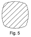
前述した態様または構造の各々について、前記要素から間隔を開けてラベルパネルを設けることができる。好ましくは、容器は、周方向に間隔を開けて設けられた偶数のフレア状の真空補正要素を有し、これにより、側壁の支持を向上させることができる。リブ付き、または段付きの眉形状部(eyebrows)を領域の閉鎖端に近接して設けてもよい。各領域または要素は、先端部と、移行部と、リッジ(ridge:山)で区画される側部を含むことができる。好ましくは、領域の各々は、略平面を形成する。前記容器は、例えば、4つの要素を有してもよく、それにより熱間充填の前後に容器本体部の横断面が略正方形となる。前記容器本体部は、ラベルを有さなくてもよい。パネルを凹状とし、装飾的特徴で装飾してもよい。 For each of the previously described aspects or structures, a label panel can be provided spaced from the element. Preferably, the container has an even number of flared vacuum correction elements spaced apart in the circumferential direction, thereby improving side wall support. Ribbed or stepped eyebrows may be provided proximate the closed end of the region. Each region or element can include a tip, a transition, and a side defined by a ridge. Preferably, each of the regions forms a substantially plane. The container may have, for example, four elements, so that the cross section of the container body is substantially square before and after hot filling. The said container main-body part does not need to have a label. The panel may be concave and decorated with decorative features.
発明者らは、図面に示した容器は軽量化できることを発見した。容器本体部は、選択的に、ラベルなしのグリップ把持面として機能することが可能であり、また、ラベルパネルはラベルを受ける面を提供する。グリップ把持面は領域の形状により強化される。 The inventors have discovered that the container shown in the drawing can be reduced in weight. The container body can optionally function as an unlabeled grip gripping surface, and the label panel provides a surface for receiving the label. The grip gripping surface is reinforced by the shape of the region.
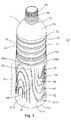
容器10は、熱間充填することが可能であり、密閉された底部12と、上部14と、ラベルパネル16と、本体部18とを含む。底部12は、好ましくは円形であり、周方向のヒール20と、スタンディングリング22と、凹部24とを含む。ヒール20は、本体部18から円形のスタンディングリング22まで下向きに延出している。好ましくは、本体部18は滑らかにヒール20に徐変し、これは、本体部18とヒール20との間で追加の構造(図示せず)を取り囲む。凹部24は、どのような種類でもよい。例えば、凹部24は、従来の放射状の補強リブを含んでもよいし、硬いか、または、内部真空に反応して変形し、容器10の真空補正機能と一緒に作用するよう構成されてもよいし、その他の構造を有してもよい。
The
上部14は、上部ラベルバンパー30と、円筒部32と、ドーム34と、ネック36と、ねじ山40を含む終端部38とを含む。上部ラベルバンパー30は、ラベルパネル16の境界線を区画する。円筒部32は、好ましくは、上向き、かつ内向きにネック36まで延出するドーム34の垂直長さに対して短い。本発明は、大きい口(図示せず)を有する容器も包含する。ねじ山40は、熱間充填時に、ふた(図示せず)の対応するねじ山を受ける。
The
図1に示したように、ラベルパネル16は、上部バンパー30から下部バンパー(後述する)へ延出し、好ましくは、その外周にラベルを貼ることができるよう、円筒形である。ラベルパネル16は、輪の強度および楕円度を向上させる(すなわち、楕円度を抑制または低減する)ために、選択的に、図1に示したリブ46を含むことができる。この点に関し、図1に示したように、リブ46を有する容器は、リブを有さない容器と区別するため、符号10'を付けて示す。容器10の本体部18は、容器10'の本体部と同一である。本明細書中の説明において、容器10への言及箇所は、そうではないと明記しない限り、容器10および10'の両方を指す。ラベル17の一部の概略を図2に示す。
As shown in FIG. 1, the
本体部18は、側壁48と、その上端部にある下部ラベルバンパー50と、各々が領域群を含む4つの真空補正要素54とを含む。図2に全体を示した前記要素は、説明の目的で、上向きであると称し、要素54aと称する。近接する要素は、下向きであると称し、要素54bと称する。図1、図2、および図3の実施形態で示したように、上向きの要素54aは、各側に下向きの要素54bを有し、下向きの要素54bの各々は、各側に上向きの要素54aを有する。
The
要素54aの形状を本明細書でV字形状と称するが、V字形状という用語は、尖頭状、円弧、または円弧よりも曲率が小さいまたは大きいその他の湾曲形状の、閉鎖端70を包含する。V字形状という用語は、中間部に対して一端が狭くなっている、すなわち一般的に「V」の字を構成すると考えられる任意の形状を包含し、また、互いに平行な、または閉鎖端70から外側に延出する側を包含する。本発明はまた、特許請求の範囲の特定の用語に従って、V字形状でない要素も包含する。
Although the shape of the element 54a is referred to herein as a V-shape, the term V-shape encompasses a
図面に示したように、各要素54aは、丸みを有する先端部80と、先端部80から外向きかつ下向きに延出する1対の対向する曲線を有する移行部82および84と、移行部82および84から基本的に下向きに延出する1対の側部86および88と、側部86および88の下端部から外向きにフレア状に開放された1対の端部90および92とを含み、また、これらによって区画される。先端部80および移行部82および84は、閉鎖端70を区画する。間隔が開いた端部90および92は、開放端72を区画する。
As shown in the drawings, each element 54a has a rounded
各要素54は、第1の領域56と、第2の領域58と、第3の領域60と、第4の領域62とを含むことができる。好ましくは、各領域は、近接する領域からそれ自体を分離するリッジを有する。例えば、第1の領域56は、領域56の一部の境界線を区画し、要素の開放端72に向かって開放されているリッジ156を有することができる。第2の領域58は、領域58の一部の境界線を区画し、要素の開放端72に向かって開放されているリッジ158を有することができる。同様に、第3の領域60は、領域60の一部の境界線を区画し、かつ、要素の開放端72に向かって開放されているリッジ160を有することができる。そして、第4の領域62は、図面に示した実施形態において、真空補正要素54の外側の境界線を区画するリッジ162を有する。
Each element 54 can include a
第1の領域56は、第2の領域58の開放端の中にはまっており、従って、第2の領域58と入れ子状になっている。好ましくは、第1の領域56の比較的平坦な表面の大部分は、第2の領域58を区画するリッジ158内に位置する。同様に、第2の領域58の比較的平坦な表面の大部分は、第3の領域60を区画するリッジ160内に位置し、第3の領域60の比較的平坦な表面の大部分は、第4の領域62を区画するリッジ162内に位置する。図面に示した実施形態において、平坦な表面の全領域は、対応する上位領域のリッジ内に位置する。好ましくは、各領域の表面は、成形したまま(as−molded)の状態では略平坦である。各領域の境界線は、外側の領域(すなわち、図面に示した実施形態の第4の領域62)の境界線と同じ基本形状を有する。
The
各リッジは、参照符号100で表わす構造を有することができ、各リッジ156、158,160、および162に適用することができる。図8は、縦方向の断面において、アウター部102と、中間部104と、インナー部106とを含む、リッジ100の各部分の概略を示す図である。リッジのインナー部106は、その領域の大きくて比較的平坦な表面と中間部104との間で移行部を形成する。好ましくは、各中間部104は、下向きの要素54b(図7および8に示した)の場合は外向き、かつ下向きに傾斜し、上向きの要素54aの場合は外向き、かつ上向きに傾斜している。リッジのアウター部102は、中間部104と近接する領域との間で移行部を形成し、また、第4の領域162のリッジ100については、領域62の表面と閉鎖端70の終端部66aおよび67bとの間で移行部を形成する。
Each ridge can have a structure represented by reference numeral 100 and can be applied to each
図7は、縦方向の断面において、各領域の好適な構造を示す図である。各領域は、その閉鎖端に向かう方向に、内向きに傾斜している。例えば、下向きの要素54bの第1の領域56は、下向き、かつ内向きに傾斜している。リッジ156は外向きに延出し、第2の領域58はリッジ156から下向き、かつ内向きに延出している。同様に、リッジ158は外向きに延出し、第3の領域60は下向き、かつ内向きに延出し、リッジ160は外向きに延出し、第4の領域62は下向きにリッジ162へ延出している。各領域は、約4〜8度傾斜している。本発明は、縦軸に対して任意の領域の向きを包含する。
FIG. 7 is a diagram showing a preferred structure of each region in the longitudinal section. Each region is inclined inward in a direction toward its closed end. For example, the
熱間充填前、すなわち成形したままの状態では、第3の領域60の閉鎖端の先端(すなわち、リッジ160のインナー部106に近接する縦方向の中心線Cにおける、領域60の平坦部分)は、第2の領域58の閉鎖端の先端(すなわち、リッジ158のインナー部106に近接する縦方向の中心線Cにおける、領域58の平坦部分)に対して内向きに後退(recessed)しており、第2の領域58の閉鎖端の先端(すなわち、リッジ158のインナー部106に近接する縦方向の中心線Cにおける、領域58の平坦部分)は、第1の領域56の閉鎖端の先端(すなわち、リッジ156のインナー部106に近接する縦方向の中心線Cにおける、領域56の平坦部分)に対して内向きに後退している。
Before hot filling, i.e., as-formed, the tip of the closed end of the third region 60 (i.e., the flat portion of the
先端部の内向きに後退した部分の角度は、好ましくは小さく、内向きに後退した先端部(上記で定義した)同士の間に引いた線が好ましくは約8度未満、より好ましくは約4度未満となるようにし、ゼロであったり、図示したものとは反対側に傾斜していてもよい。リッジ160および162の半径方向寸法は、領域の内向きの傾斜を相殺するために、リッジ156および158の半径方向寸法と比べて大きくなっている。
The angle of the inwardly retracted portion of the tip is preferably small and the line drawn between the inwardly retracted tips (defined above) is preferably less than about 8 degrees, more preferably about 4 The angle may be less than 0 degrees and may be zero or may be inclined to the opposite side of the illustrated one. The radial dimensions of the
本発明は、特定の領域やリッジの構成に制限されない。例えば、本発明は、熱間充填容器技術を熟知した当業者なら理解できるように、任意の数の領域を有する要素、最も外側の領域の外側の構造、領域および要素の形状の変形、およびリッジの断面形状の変形を包含する。 The present invention is not limited to a particular region or ridge configuration. For example, the present invention provides elements having any number of regions, structures outside the outermost region, deformations of regions and element shapes, and ridges, as will be appreciated by those skilled in the art of hot fill vessel technology. Including deformation of the cross-sectional shape.
本体部18の側壁48は、図1に最も良く示されているように、略垂直の、近接する要素54同士の間に位置する中間部分64を含む。上部終端部66aおよび66bは、側壁48上で、各々要素54aおよび54bの上に位置している。上部終端部66aの形状は、上向きの要素54aのための形状と、下向きの要素54bのための別の形状66bとを有する。上部終端部66aの形状は、一部は、要素54aの閉鎖端70により区画される。上部終端部66bの形状は、一部は、要素54bの開放端72により区画される。
The side wall 48 of the
下部終端部67aおよび67bは、各々要素54aおよび54bの下に位置している。下部終端部67aの形状は、上向きの要素54aのための形状と、下向きの要素54bのための別の形状67bとを有する。下部終端部67aの形状は、一部は、要素54aの開放端72により区画され、下部終端部67bの形状は、一部は、要素54bの閉鎖端70により区画される。
側壁48はまた、閉鎖端70の上部終端部66と中間部分64との間の側壁移行部68を含む。好ましくは、側壁部64、66、および68は滑らかに互いに融合する。
The sidewall 48 also includes a
発明者らは、各領域56、58、60、62の開放端は、横軸に対して内向きのたわみに対し、わずかな耐性しかないが、リッジ156、158、160、および162は要素の魅力的な形状を維持し、熱間充填に反応してよじれたり、見苦しく押し下げられる傾向を低減することを理論化している。さらに、リッジ100は、要素54の全体にわたって支持をするよう配分されている。
The inventors have noted that the open ends of each
偶数の要素54を有する容器では、フレア状の端部90および92は、近接する要素の狭い閉鎖端70に向かって外向きに延出している。例えば、図2に示した下向きの要素54aの右側のフレア状の端部90は、要素54aの縦方向の中心線から右向きに、近接する下向きの要素54bに向かって延出している。従って、フレア状の端部90は、閉鎖端70を狭くすることにより作られるスペースに延出している。フレア状の端部90(および対向するフレア状の端部92)におけるリッジ100は、支持しなければ補強されず、高レベルの応力を受け易い領域で側壁48を支持する。
In containers having an even number of elements 54, the flared ends 90 and 92 extend outwardly toward the narrow
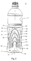
第2の実施形態の容器10aを、図9Aおよび図9Bに示す。容器10aは、熱間充填することが可能であり、密閉された底部12aと、上部14aと、ラベルパネル16aと、本体部18aとを含む。底部12a、上部14a、およびラベルパネル16aは、第1の実施形態の容器10および10'に関して説明した通りである。
A container 10a of the second embodiment is shown in FIGS. 9A and 9B. The container 10a can be hot-filled and includes a sealed
本体部18aは、全てが上向きである要素55を含む。図示したように、容器10aは、4つの上向きの要素55を含み、前記要素は、好ましくは、各要素55が他の要素55と直径方向に対向するように、本体部18aの側壁48aの周りで等間隔が開けられている。
The
要素55の形状を本明細書でV字形状と称するが、V字形状という用語は、尖頭状、円弧、または円弧よりも曲率が小さいまたは大きいその他の曲線形状の閉じた端部70aを包含する。V字形状という用語は、中間部に対して一端が狭くなっている、すなわち一般的に「V」の字を構成すると考えられる任意の形状を包含し、また、互いに平行な、または閉鎖端70aから外側に延出する側を包含する。本発明はまた、V字形状でない要素も包含する。
Although the shape of
各要素55は、丸みを有する先端部80aと、先端部80aから外向きかつ下向きに延出する1対の対向する曲線を有する移行部82aおよび84aと、移行部82aおよび84aから基本的に下向きに延出する1対の側部86aおよび88aと、側部86aおよび88aの下端部から延出する1対の端部90aおよび92aとを含み、また、これらによって区画される。先端部80aおよび移行部82aおよび84aは、閉鎖端70aを区画する。間隔が開いた端部90aおよび92aは、開放端72aを区画する。本発明は、側部86aおよび86bの略直線形の延出部であり、わずかに内向きである、外向きにフレア状に開放された部分90aおよび90bを包含する。
Each
各要素55は、第1の領域56aと、第2の領域58aと、第3の領域60aと、第4の領域62aとを含むが、これらの各々は、第1の実施形態10に関して説明した通りである。本発明は、特定の領域やリッジの構造に制限されない。例えば、本発明は、熱間充填容器技術を熟知した当業者なら理解できるように、任意の数の領域を有する要素、最も外側の領域の外側の構造、領域および要素の形状の変形、およびリッジの断面形状の変形を包含する。
Each
本体部18aはまた、各要素55の閉鎖端で、曲線を有する移行部82aおよび84aに近接して配置された1対の眉形状部83および85を含む。眉形状部83および85は、曲線を有する移行部82および84の輪郭を基本的にたどった、湾曲した部分である。
The
本体部18aの側壁48aは、略垂直の、近接する要素55同士の間に位置する中間部分164aを含む。上部終端部166aは、側壁48a上で、各々要素55の上に位置している。上部終端部166aの形状は、一部は、要素55の閉鎖端70aにより区画される。下部終端部167aは、各々要素55の下に位置している。下部終端部167aの形状は、一部は、要素55の開放端72aにより区画される。側壁48aはまた、閉鎖端70aの上部終端部166aと中間部分164aとの間の側壁移行部168aを含む。好ましくは、側壁部164a、166a、および168aは滑らかに互いに融合する。眉形状部83および85は、中間側壁部164aおよび上部側壁部166aに位置する。
The
発明者らは、各領域56a、58a、60a、62aの開放端は、横軸に対して内向きのたわみに対し、わずかな耐性しかないが、そのリッジは要素の魅力的な形状を維持し、熱間充填に反応してよじれたり、見苦しく押し下げられる傾向を低減することを理論化している。
The inventors have noted that the open end of each
要素55は、先端部80a付近で狭くなっており、眉形状部83および85は、近接する要素55の上端部の間で上部側壁部166aを支持している。眉形状部83および85は、好ましくは、前述した領域56、58、60、および62と同じリッジ100構造により区画される。従って、眉形状部83および85は、支持しなければ補強されず、高レベルの応力を受け易い領域で側壁48aを支持することができるが、これが、構成と条件によっては、熱間充填時のよじれを防止することになる。図示しないが、本発明は、側壁の周りに配置され、開放端を有して上向きになっている要素も包含する。
The
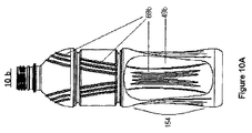
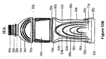
図10A〜図10Cを参照すると、第3の実施形態の容器10bが示されている。容器10bは、熱間充填することが可能であり、密閉された底部12bと、上部14bと、ラベルパネル16bと、本体部18bとを含む。底部12b、上部14b、およびラベルパネル16bは、第1の実施形態の容器10および10'に関して説明した通りである。本体部18bは、第1の実施形態の容器10および10'に関して説明した要素54と同じ要素154を含む。
Referring to FIGS. 10A to 10C, a container 10b of a third embodiment is shown. The container 10b can be hot-filled and includes a sealed
図示したように、容器10bは、全てが上向きであり、本体部18bの側壁48bの周りに間隔を開けて設けられ、互いの間にパネル49bが配置されている要素154を含む。容器10bは、好ましくは、2つの上向きの要素54と2つのパネル49bとを有し、これらは、好ましくは、本体部18bの側壁48bの周りで等間隔を開けて交互に配置されている。さらに、要素154は、好ましくは直径方向に対向し、パネル49bも、好ましくは直径方向に対向している。あるいは、本実施形態は、上向きの要素154(図10A〜図10Cに示した)の代わりに、下向きの要素155(図11A〜図11Cに示した)を組込んでもよい。
As shown, the container 10b includes
要素154同士の間に配置されたパネル49bは、好ましくは、図10Bに示したように、内向きの凹部を有する。さらに、パネル49bは、本体部18bの側壁48bに一体的に形成された装飾的特徴69bを含んでもよい。例えば、装飾的特徴69bは、図10Aおよび図10Cに示したように、虹の弧の部分を含むことができる。虹の弧の部分は、1つのパネル49bの最下部から最上部まで垂直に、ラベルパネル16bを横切って垂直に、ネック36bの両側でドーム34bを横切って、もう1つのパネル49bの最上部から最下部まで垂直に延出し、虹の弧を形成している。虹の弧は、連続的であってもよいし、図10A〜図10Cに示したように、構造要素に近接する領域(例えば、上部ラベルバンパー30bおよび下部ラベルバンパー50b)で中断されていてもよい。また、図10A〜図10Cにおいて、容器10bは、ラベルパネル16bにリブ46bが付いた状態で示してあるが、ラベルパネル16bはリブ46bなしで設けてもよい。
The
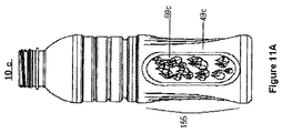
図11A〜図11Cを参照すると、第4の実施形態の容器10cが示されている。容器10cは、熱間充填することが可能であり、密閉された底部12cと、上部14cと、ラベルパネル16cと、本体部18cとを含む。底部12c、上部14c、およびラベルパネル16cは、第1の実施形態の容器10および10'に関して説明した通りである。本体部18bは、第1の実施形態の容器10および10'に関して説明した要素54と同じ要素155を含む。
Referring to FIGS. 11A to 11C, a
図示したように、第4の実施形態の容器10c(図11A〜図11Cを参照)は、本体部18cの側壁48cの周りに間隔を開けて設けられ、互いの間にパネル49cが配置されている要素155を含む。容器10cは、好ましくは、偶数の要素155およびパネル49cを含み、これらは、各要素155が他の要素155と直径方向に対向するように、また、各パネル49cが他のパネル49cと直径方向に対向するように、本体部18cの側壁48cの周りで等間隔が開けられている。要素155同士の間に配置されたパネル49cは、好ましくは、図11Bに示したように、内向きに凹状となった表面を有し、図11Aおよび図11Cに示したように、水滴の浮き彫りのような装飾的特徴69cを含んでもよい。あるいは、本実施形態は、下向きの要素155(図11A〜図11Cに示した)の代わりに、上向きの要素154(図10A〜図10Cに示した)を組込んでもよい。また、図11A〜図11Cにおいて、容器10cは、ラベルパネル16cにリブ46cが付いた状態で示してあるが、ラベルパネル16cはリブ46cなしで設けてもよい。
As illustrated, the
作業時に、容器10は、例えば185°Fなどの高い熱間充填温度で製品を受けることができる。好ましくは、容器10は、熱間充填容器用として典型的な範囲の固有粘度を有するプラスチックで形成する。容器10は、熱硬化段階を有する2段階延伸ブロー成形工程など、任意のブロー成形工程で成形することができる。本発明は、2段階工程に制限されず、むしろ、容器、本明細書に記載した一般的な技術を用いた任意の容器を製造するための任意の工程を包含する。例えば、本発明は、本明細書に記載した1若しくはそれ以上の真空補正要素、またはその同等物を有する任意の容器を包含する。
In operation, the
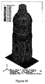
図12は、従来の熱間充填を行った後の、図2および図3に示した容器10の変形を示しており、最大の変形は、第2の領域58の概ねの中心部、また、要素54の縦方向の概ねの中心線上に位置している。図13は、従来の熱間充填を行った後の、図9Aおよび図9Bに示した容器10aの変形を示しており、最大の変形は、要素55の概ねの中心部に位置している。図14は、従来の熱間充填を行った後の、図10A〜図10Cに示した容器10bの変形を示しており、最大の変形は、要素154の概ねの中心部に位置している。
FIG. 12 shows a deformation of the
熱間充填工程時にキャップを閉めると、内部真空に反応して要素54が内向きに引張られる。中間部分64は、熱間充填後、直立した真っ直ぐな形状を有して柱を形成する。図9は、柱にほとんど変形がないことを示している。要素54の面は、熱間充填後、概ね平坦(横方向の断面)であるので、容器10は、本体部18の中心部において概ねボックス状の構造を有する一方、ラベルパネル16は円筒形を保つ。
Closing the cap during the hot filling process causes element 54 to be pulled inward in response to the internal vacuum. The
本開示は、本発明の観点を説明するものであり、容器設計および製造を熟知した当業者であれば理解するように、本開示の自明な変形態を包含するものである。 This disclosure describes aspects of the invention and encompasses obvious variations of the present disclosure, as will be appreciated by those skilled in the art of container design and manufacture.
Claims (42)
密閉された底部と、
上向きに終端部まで延出する上部と、
前記底部と前記上部との間に位置する本体部であって、周方向に間隔を開けて設けられた偶数の真空補正(vacuum compensation)要素を有する側壁を含み、当該要素の各々は略V字形状を有し、且つ第1の領域と第2の領域と第3の領域とを有し、前記第1の領域は前記第2の領域内に入れ子式に含まれ、且つ前記第2の領域は前記第3の領域内に入れ子式に含まれており、当該要素は、上端部および下端部のうちの1つにおいて基本的に閉鎖しており、この上端部および下端部のうちの1つと反対側の上端部および下端部のうちの1つにおいて基本的に開放されているものである、前記本体部と
を有するボトル。 A plastic hot-fill bottle,
A sealed bottom;
An upper part extending upward to the end part,
A body portion located between the bottom portion and the top portion, including a sidewall having an even number of vacuum compensation elements spaced circumferentially, each of which is generally V-shaped. A first region, a second region, and a third region, wherein the first region is nested within the second region, and the second region Is nested within the third region, and the element is basically closed at one of the upper end and the lower end, and one of the upper and lower ends is A bottle having the main body, which is basically opened at one of the upper end and the lower end on the opposite side.
領域の前記閉鎖端に近接して配置された、少なくとも1つの眉形状部(eye brow)を含むものである。 6. The bottle of claim 5, wherein the element further comprises
Including at least one eyebrow disposed adjacent to the closed end of the region.
領域の前記閉鎖端に近接して配置された、少なくとも1つの眉形状部を含むものである。 The bottle of claim 9, wherein the element further comprises:
It includes at least one eyebrow shaped portion disposed proximate to the closed end of the region.
第4の領域を含み、前記第3の領域は前記第4の領域内に入れ子式に含まれているものである。 The bottle of claim 14, wherein the element further comprises:
Including a fourth region, wherein the third region is nested within the fourth region.
さらに、前記本体部と前記上部との間に位置するラベルパネルと、当該ラベルパネルの少なくとも一部に配置されたラベルとを有し、前記本体部はラベルを有さないものである。 The bottle of claim 14,
Furthermore, it has a label panel located between the said main-body part and the said upper part, and the label arrange | positioned at least in part of the said label panel, and the said main-body part does not have a label.
中間部分を有し、この中間部分を介して前記要素の前記フレア状の端部が隣接する要素の閉鎖端に向かって延出するものである。 The bottle according to claim 30, wherein the main body further comprises:
An intermediate portion through which the flared end of the element extends toward the closed end of an adjacent element;
密閉された底部と、
上向きに終端部まで延出する上部と、
前記底部と前記上部との間に位置する本体部であって、周方向に間隔を開けて設けられた、少なくとも1つの真空補正要素を有する側壁を含み、当該要素の各々は、第1の領域と、第2の領域と、第3の領域とを有し、前記第1の領域は前記第2の領域内に入れ子式に含まれ、且つ前記第2の領域は前記第3の領域内に入れ子式に含まれており、当該要素は、上端部および下端部のうちの1つにおいて基本的に閉鎖しており、この上端部および下端部のうちの1つと反対側の上端部および下端部のうちの1つにおいて基本的に開放されており、前記要素の開放端は容器の側壁に滑らかに融合しているものである、前記本体部と
を有するボトル。 A plastic hot-fill bottle,
A sealed bottom;
An upper part extending upward to the end part,
A body portion located between the bottom portion and the top portion, including a sidewall having at least one vacuum correction element spaced circumferentially, each element being a first region; And a second region and a third region, wherein the first region is nested within the second region, and the second region is within the third region Nested, the element is basically closed at one of the upper end and the lower end, and the upper end and the lower end opposite to one of the upper end and the lower end A bottle having said body part, which is basically open in one of the two, wherein the open end of said element is smoothly fused to the side wall of the container.
密閉された底部と、
上向きにネックおよび終端部まで延出する上部と、
前記底部と前記上部との間に位置し、側壁を含む本体部と
を有し、この側壁は、
少なくとも2つの真空補正要素と、
少なくとも2つのパネルと
を有し、
前記要素およびパネルは、前記本体部の外周に交互に配置され、
前記真空補正要素は略V字形状を有し、この真空補正要素は、
第1の領域と、
第2の領域と、
第3の領域と
を有し、
前記第1の領域は前記第2の領域内に入れ子式に含まれ、前記第2の領域は前記第3の領域内に入れ子式に含まれており、
前記要素は、上端部および下端部のうちの1つにおいて基本的に閉鎖しており、この上端部および下端部のうちの1つと反対側の上端部および下端部のうちの1つにおいて基本的に開放されているものである
ボトル。 A plastic hot-fill bottle,
A sealed bottom;
An upper part extending upwards to the neck and end, and
A body portion located between the bottom and the top and including a sidewall, the sidewall being
At least two vacuum correction elements;
Having at least two panels;
The elements and panels are alternately arranged on the outer periphery of the main body,
The vacuum correction element has a substantially V shape,
A first region;
A second region;
A third region, and
The first region is nested within the second region, and the second region is nested within the third region;
The element is basically closed at one of the upper end and the lower end, and basically at one of the upper end and the lower end opposite to the one of the upper end and the lower end. Bottles that are open to the bottle.
Applications Claiming Priority (2)
| Application Number | Priority Date | Filing Date | Title |
|---|---|---|---|
| US91206407P | 2007-04-16 | 2007-04-16 | |
| PCT/US2008/060454 WO2008130987A1 (en) | 2007-04-16 | 2008-04-16 | Container having vacuum compensation elements |
Publications (2)
| Publication Number | Publication Date |
|---|---|
| JP2010524789A true JP2010524789A (en) | 2010-07-22 |
| JP2010524789A5 JP2010524789A5 (en) | 2011-06-02 |
Family
ID=39875870
Family Applications (1)
| Application Number | Title | Priority Date | Filing Date |
|---|---|---|---|
| JP2010504210A Pending JP2010524789A (en) | 2007-04-16 | 2008-04-16 | Container with vacuum correction element |
Country Status (4)
| Country | Link |
|---|---|
| US (1) | US8905253B2 (en) |
| JP (1) | JP2010524789A (en) |
| AU (1) | AU2008242970A1 (en) |
| WO (1) | WO2008130987A1 (en) |
Cited By (3)
| Publication number | Priority date | Publication date | Assignee | Title |
|---|---|---|---|---|
| JP2009035263A (en) * | 2007-07-31 | 2009-02-19 | Yoshino Kogyosho Co Ltd | Bottle |
| JP2013010552A (en) * | 2011-06-30 | 2013-01-17 | Yoshino Kogyosho Co Ltd | Thin-walled heat resistant round bottle |
| JP2019206394A (en) * | 2011-12-05 | 2019-12-05 | ナイアガラ・ボトリング・エルエルシー | Plastic container with varying depth ribs |
Families Citing this family (24)
| Publication number | Priority date | Publication date | Assignee | Title |
|---|---|---|---|---|
| AU2008242970A1 (en) | 2007-04-16 | 2008-10-30 | Constar International, Inc. | Container having vacuum compensation elements |
| IT1397716B1 (en) | 2009-02-05 | 2013-01-24 | Lumson Spa | CONTAINER WITH RELIEF DECORATIONS |
| US9102434B2 (en) * | 2009-07-20 | 2015-08-11 | Graham Packaging Company, L.P. | Container having compound flexible panels |
| US8556097B2 (en) * | 2011-02-16 | 2013-10-15 | Amcor Limited | Container having vacuum panel with balanced vacuum and pressure response |
| US11845581B2 (en) | 2011-12-05 | 2023-12-19 | Niagara Bottling, Llc | Swirl bell bottle with wavy ribs |
| US9132933B2 (en) | 2012-12-27 | 2015-09-15 | Niagara Bottling, Llc | Plastic container with strapped base |
| US10023346B2 (en) | 2012-12-27 | 2018-07-17 | Niagara Bottling, Llc | Swirl bell bottle with wavy ribs |
| USD742238S1 (en) * | 2012-05-04 | 2015-11-03 | Robinsons Soft Drinks Limited | Bottle |
| USD741714S1 (en) * | 2012-10-09 | 2015-10-27 | Robinsons Soft Drinks Limited | Bottle |
| USD771497S1 (en) * | 2014-06-11 | 2016-11-15 | The Coca-Cola Company | Bottle |
| USD778677S1 (en) * | 2015-04-07 | 2017-02-14 | Thermos L.L.C. | Bottle |
| USD780517S1 (en) * | 2015-04-08 | 2017-03-07 | Thermos L.L.C. | Lid and bottle combination |
| USD778114S1 (en) * | 2015-04-08 | 2017-02-07 | Thermos L.L.C. | Bottle |
| USD790923S1 (en) * | 2015-04-08 | 2017-07-04 | Thermos L.L.C. | Bottle |
| US20160316946A1 (en) * | 2015-05-01 | 2016-11-03 | Family Hospitality, Llc | Reusable children's drinking cup |
| USD798112S1 (en) * | 2015-11-09 | 2017-09-26 | Gold Bond, Inc. | Tumbler |
| US10336524B2 (en) | 2016-02-09 | 2019-07-02 | Pepsico, Inc. | Container with pressure accommodation panel |
| USD781106S1 (en) * | 2016-03-01 | 2017-03-14 | Thermos L.L.C. | Bottle and lid combination |
| USD775495S1 (en) * | 2016-03-01 | 2017-01-03 | Thermos L.L.C. | Bottle |
| USD774359S1 (en) * | 2016-03-01 | 2016-12-20 | Thermos L.L.C. | Bottle with sidewall design |
| USD774826S1 (en) * | 2016-03-01 | 2016-12-27 | Thermos L.L.C. | Bottle with sidewall design |
| USD918043S1 (en) | 2019-06-17 | 2021-05-04 | S. C. Johnson & Son, Inc. | Bottle |
| USD907508S1 (en) | 2019-06-17 | 2021-01-12 | S. C. Johnson & Son, Inc. | Bottle |
| USD924064S1 (en) | 2019-06-17 | 2021-07-06 | S. C. Johnson & Son, Inc. | Bottle |
Citations (13)
| Publication number | Priority date | Publication date | Assignee | Title |
|---|---|---|---|---|
| JPS55179110U (en) * | 1979-06-11 | 1980-12-23 | ||
| JPS6367411U (en) * | 1986-10-24 | 1988-05-06 | ||
| US4749092A (en) * | 1979-08-08 | 1988-06-07 | Yoshino Kogyosho Co, Ltd. | Saturated polyester resin bottle |
| JPH0410011U (en) * | 1990-05-14 | 1992-01-28 | ||
| JPH10230919A (en) * | 1997-02-19 | 1998-09-02 | Yoshino Kogyosho Co Ltd | Plastic bottle |
| JPH11193080A (en) * | 1997-09-09 | 1999-07-21 | Johnson & Johnson Consumer Co Inc | Tapered closure and its manufacture |
| JP2002513720A (en) * | 1998-05-01 | 2002-05-14 | クラウン コーク アンド シール テクノロジーズ コーポレーション | Plastic container for filling heated material with spaced-apart arched ribs |
| US20030015491A1 (en) * | 2001-07-17 | 2003-01-23 | Melrose David Murray | Plastic container having an inverted active cage |
| US20050121408A1 (en) * | 2003-12-03 | 2005-06-09 | Deemer David A. | Hot fillable container |
| US20050218108A1 (en) * | 2004-04-01 | 2005-10-06 | Constar International Inc. | Hot-fill bottle having flexible portions |
| JP2005343474A (en) * | 2004-05-31 | 2005-12-15 | Yoshino Kogyosho Co Ltd | Container made of synthetic resin |
| JP2006327638A (en) * | 2005-05-27 | 2006-12-07 | Ishizuka Glass Co Ltd | Bottle made of polyethylene terephthalate resin |
| JP2007076717A (en) * | 2005-09-16 | 2007-03-29 | Coca Cola Co:The | Plastics bottle |
Family Cites Families (22)
| Publication number | Priority date | Publication date | Assignee | Title |
|---|---|---|---|---|
| US3212661A (en) * | 1964-08-25 | 1965-10-19 | Adell Chemical Corp | Device for holding additive for motor vehicle windshield washing liquid |
| SE504354C2 (en) * | 1986-02-28 | 1997-01-20 | Toyo Seikan Kaisha Ltd | Process for making a biaxially drawn vessel and biaxially drawn polyester vessel |
| US5101990A (en) * | 1990-03-23 | 1992-04-07 | Continental Pet Technologies, Inc. | Stretch blow molded oblong or oval container |
| JPH0410011A (en) | 1990-04-27 | 1992-01-14 | Oki Electric Ind Co Ltd | Clock signal distribution circuit |
| US5141120A (en) | 1991-03-01 | 1992-08-25 | Hoover Universal, Inc. | Hot fill plastic container with vacuum collapse pinch grip indentations |
| US5141121A (en) | 1991-03-18 | 1992-08-25 | Hoover Universal, Inc. | Hot fill plastic container with invertible vacuum collapse surfaces in the hand grips |
| US5908128A (en) | 1995-07-17 | 1999-06-01 | Continental Pet Technologies, Inc. | Pasteurizable plastic container |
| US7137520B1 (en) | 1999-02-25 | 2006-11-21 | David Murray Melrose | Container having pressure responsive panels |
| ATE328801T1 (en) | 2000-10-19 | 2006-06-15 | Graham Packaging Co | HOT FILL CONTAINERS WITH SEPARATE RIGID HANDLES AND EXPANSION WALL PARTS |
| CA2368491C (en) | 2001-01-22 | 2008-03-18 | Ocean Spray Cranberries, Inc. | Container with integrated grip portions |
| US6662960B2 (en) | 2001-02-05 | 2003-12-16 | Graham Packaging Company, L.P. | Blow molded slender grippable bottle dome with flex panels |
| AU2003295405B2 (en) | 2003-03-12 | 2010-04-22 | Plastipak Packaging, Inc. | Container exhibiting improved top load performance |
| JP4864316B2 (en) * | 2003-11-26 | 2012-02-01 | 株式会社吉野工業所 | Heat-resistant bottle type container made of synthetic resin |
| US7258244B2 (en) * | 2004-10-04 | 2007-08-21 | Graham Packaging Company L.P. | Hot-fill plastic container and method of manufacture |
| US7416090B2 (en) | 2004-10-08 | 2008-08-26 | Constar International Inc. | Round type hot fillable container with deformable label panel |
| USD579780S1 (en) * | 2005-06-09 | 2008-11-04 | Sidel Participations | Bottle |
| MX2008015335A (en) * | 2006-06-02 | 2016-08-19 | Plastipak Packaging Inc | Container having vacuum compensation elements. |
| US7581654B2 (en) | 2006-08-15 | 2009-09-01 | Ball Corporation | Round hour-glass hot-fillable bottle |
| AU2008242970A1 (en) | 2007-04-16 | 2008-10-30 | Constar International, Inc. | Container having vacuum compensation elements |
| US20100219154A1 (en) | 2007-04-16 | 2010-09-02 | Constar International, Inc. | Container having vacuum compensation elements |
| USD601030S1 (en) | 2008-02-15 | 2009-09-29 | Sidel Participations | Bottle |
| USD602783S1 (en) | 2008-02-15 | 2009-10-27 | Sidel Participations | Bottle |
-
2008
- 2008-04-16 AU AU2008242970A patent/AU2008242970A1/en not_active Abandoned
- 2008-04-16 WO PCT/US2008/060454 patent/WO2008130987A1/en active Application Filing
- 2008-04-16 JP JP2010504210A patent/JP2010524789A/en active Pending
- 2008-04-16 US US12/595,723 patent/US8905253B2/en active Active - Reinstated
Patent Citations (13)
| Publication number | Priority date | Publication date | Assignee | Title |
|---|---|---|---|---|
| JPS55179110U (en) * | 1979-06-11 | 1980-12-23 | ||
| US4749092A (en) * | 1979-08-08 | 1988-06-07 | Yoshino Kogyosho Co, Ltd. | Saturated polyester resin bottle |
| JPS6367411U (en) * | 1986-10-24 | 1988-05-06 | ||
| JPH0410011U (en) * | 1990-05-14 | 1992-01-28 | ||
| JPH10230919A (en) * | 1997-02-19 | 1998-09-02 | Yoshino Kogyosho Co Ltd | Plastic bottle |
| JPH11193080A (en) * | 1997-09-09 | 1999-07-21 | Johnson & Johnson Consumer Co Inc | Tapered closure and its manufacture |
| JP2002513720A (en) * | 1998-05-01 | 2002-05-14 | クラウン コーク アンド シール テクノロジーズ コーポレーション | Plastic container for filling heated material with spaced-apart arched ribs |
| US20030015491A1 (en) * | 2001-07-17 | 2003-01-23 | Melrose David Murray | Plastic container having an inverted active cage |
| US20050121408A1 (en) * | 2003-12-03 | 2005-06-09 | Deemer David A. | Hot fillable container |
| US20050218108A1 (en) * | 2004-04-01 | 2005-10-06 | Constar International Inc. | Hot-fill bottle having flexible portions |
| JP2005343474A (en) * | 2004-05-31 | 2005-12-15 | Yoshino Kogyosho Co Ltd | Container made of synthetic resin |
| JP2006327638A (en) * | 2005-05-27 | 2006-12-07 | Ishizuka Glass Co Ltd | Bottle made of polyethylene terephthalate resin |
| JP2007076717A (en) * | 2005-09-16 | 2007-03-29 | Coca Cola Co:The | Plastics bottle |
Cited By (4)
| Publication number | Priority date | Publication date | Assignee | Title |
|---|---|---|---|---|
| JP2009035263A (en) * | 2007-07-31 | 2009-02-19 | Yoshino Kogyosho Co Ltd | Bottle |
| JP2013010552A (en) * | 2011-06-30 | 2013-01-17 | Yoshino Kogyosho Co Ltd | Thin-walled heat resistant round bottle |
| JP2019206394A (en) * | 2011-12-05 | 2019-12-05 | ナイアガラ・ボトリング・エルエルシー | Plastic container with varying depth ribs |
| JP7236946B2 (en) | 2011-12-05 | 2023-03-10 | ナイアガラ・ボトリング・エルエルシー | Plastic container with ribs of varying depth |
Also Published As
| Publication number | Publication date |
|---|---|
| WO2008130987A1 (en) | 2008-10-30 |
| AU2008242970A1 (en) | 2008-10-30 |
| US8905253B2 (en) | 2014-12-09 |
| US20100219153A1 (en) | 2010-09-02 |
Similar Documents
| Publication | Publication Date | Title |
|---|---|---|
| JP2010524789A (en) | Container with vacuum correction element | |
| US8267266B2 (en) | Container having vacuum compensation elements | |
| US7347339B2 (en) | Hot-fill bottle having flexible portions | |
| US8152010B2 (en) | Container structure for removal of vacuum pressure | |
| US8127955B2 (en) | Container structure for removal of vacuum pressure | |
| US20060131257A1 (en) | Plastic container with champagne style base | |
| US8950611B2 (en) | Container comprising a bottom equipped with a deformable membrane | |
| KR960007288B1 (en) | One piece self-standing blow molded plastic containers and process for manufacturing the same | |
| JP4679038B2 (en) | Synthetic resin bottle type container | |
| US20100176081A1 (en) | Container having meta-stable panels | |
| JP2008522919A (en) | Improved plastic high temperature filling type container and method for manufacturing the same | |
| EP2764967B1 (en) | Mold for blow molding a hot-fill container with increased stretch ratios | |
| US20150328825A1 (en) | Method for blow molding a hot-fill container with increased stretch ratios | |
| JP2008532867A (en) | Thermoplastic container filled with high temperature liquid | |
| US10717560B2 (en) | Container comprising an arched base having stiffening bosses distributed in interlaced annular bands | |
| CN110770134A (en) | Container with bottom base provided with notches | |
| US20100219154A1 (en) | Container having vacuum compensation elements | |
| US10343832B2 (en) | Container provided with a convex invertible diaphragm | |
| AU2007256722B2 (en) | Container having vacuum compensation elements | |
| PL202047B1 (en) | Plastic bottle |
Legal Events
| Date | Code | Title | Description |
|---|---|---|---|
| A521 | Written amendment |
Free format text: JAPANESE INTERMEDIATE CODE: A523 Effective date: 20110416 |
|
| A621 | Written request for application examination |
Free format text: JAPANESE INTERMEDIATE CODE: A621 Effective date: 20110416 |
|
| A131 | Notification of reasons for refusal |
Free format text: JAPANESE INTERMEDIATE CODE: A131 Effective date: 20130219 |
|
| A02 | Decision of refusal |
Free format text: JAPANESE INTERMEDIATE CODE: A02 Effective date: 20130716 |