JP2010524045A - Universal PCB Printer ICC Profile Selection Method - Google Patents
Universal PCB Printer ICC Profile Selection Method Download PDFInfo
- Publication number
- JP2010524045A JP2010524045A JP2010503014A JP2010503014A JP2010524045A JP 2010524045 A JP2010524045 A JP 2010524045A JP 2010503014 A JP2010503014 A JP 2010503014A JP 2010503014 A JP2010503014 A JP 2010503014A JP 2010524045 A JP2010524045 A JP 2010524045A
- Authority
- JP
- Japan
- Prior art keywords
- color
- receiving member
- substrate
- universal
- profile
- Prior art date
- Legal status (The legal status is an assumption and is not a legal conclusion. Google has not performed a legal analysis and makes no representation as to the accuracy of the status listed.)
- Pending
Links
Images

Classifications
-
- H—ELECTRICITY
- H04—ELECTRIC COMMUNICATION TECHNIQUE
- H04N—PICTORIAL COMMUNICATION, e.g. TELEVISION
- H04N1/00—Scanning, transmission or reproduction of documents or the like, e.g. facsimile transmission; Details thereof
- H04N1/46—Colour picture communication systems
- H04N1/56—Processing of colour picture signals
- H04N1/60—Colour correction or control
- H04N1/603—Colour correction or control controlled by characteristics of the picture signal generator or the picture reproducer
-
- H—ELECTRICITY
- H04—ELECTRIC COMMUNICATION TECHNIQUE
- H04N—PICTORIAL COMMUNICATION, e.g. TELEVISION
- H04N1/00—Scanning, transmission or reproduction of documents or the like, e.g. facsimile transmission; Details thereof
- H04N1/46—Colour picture communication systems
- H04N1/56—Processing of colour picture signals
- H04N1/60—Colour correction or control
- H04N1/6097—Colour correction or control depending on the characteristics of the output medium, e.g. glossy paper, matt paper, transparency or fabrics
Abstract
受け部材の基板にマルチカラー画像を形成する方法において、受け部材の基板の物理的特性及び印刷プロセスの特徴に基づいて、カスタムカラープロファイルのデータベースが構築される。クラスター化されたカスタムプロファイルからの受け部材の基板についての物理的特性に基づいて、ユニバーサルカラープロファイルの集合が決定される。ユニバーサルカラープロファイルの集合から目的の受け部材の基板に1つのユニバーサルカラープロファイルが割り当てられる。その後、割り当てられた1つのユニバーサルカラープロファイルを用いてマルチカラートナー画像を形成するように受け部材の基板における異なる画素位置に種々の色の組み合わせを形成するトナー顔料の少なくとも3つの異なる色のトナーにより、マルチカラートナー画像が受け部材の基板に形成される。客観的フィードバック又は主観的フィードバックに基づいて、選択された1つのユニバーサルカラープロファイルが修正される又は異なるユニバーサルカラープロファイルが選択される。In the method of forming a multicolor image on a receiving member substrate, a database of custom color profiles is constructed based on the physical characteristics of the receiving member substrate and the characteristics of the printing process. A set of universal color profiles is determined based on the physical properties of the receiving member substrate from the clustered custom profile. One universal color profile is assigned to the substrate of the target receiving member from the set of universal color profiles. Thereafter, with at least three different color toners of the toner pigment forming various color combinations at different pixel locations on the substrate of the receiving member to form a multi-color toner image using one universal color profile assigned. A multi-color toner image is formed on the substrate of the receiving member. Based on objective or subjective feedback, one selected universal color profile is modified or a different universal color profile is selected.
Description
本発明は色再現に関し、特に、カラートナー画像が、カラー静電写真プリンタであって、各々の既知の受け部材基板に対してユニバーサルプロファイルを割り当てるようにユニバーサルプロファイル及び方法を設定する受け部材に堆積される、カラー静電写真プリンタに関する。 The present invention relates to color reproduction, and in particular, a color toner image is a color electrostatographic printer, deposited on a receiving member that sets a universal profile and method to assign a universal profile to each known receiving member substrate. A color electrostatographic printer.
例えば、イーストマンコダック社(米国ニューヨーク州ロチェスター市)製のNextPress 2100プリンタ等の既知の種類のディジタル静電写真モジュラプリント装置において、複数のカラートナー画像が、タンデムに配置された複数のカラーイメージングモジュールに順次に形成され、それらの複数のトナー画像は、それらのモジュールを通って移動する搬送ウェブに接着された受け部材に対して成功裏に静電気的に転写される。この種の市販されている印刷装置は、典型的には、個別の色分離トナー画像の受け部材に対する転写のためにそれぞれの色印刷モジュールにおいて中間転写部材を用いる。勿論、他の静電写真プリンタにおいては、各々の色分離トナー画像が、受け部材に対して直接、転写されることが可能である。 For example, in a known type of digital electrostatographic modular printing device such as NextPress 2100 printer manufactured by Eastman Kodak Company (Rochester, NY, USA), a plurality of color imaging modules in which a plurality of color toner images are arranged in tandem. The plurality of toner images are successively transferred electrostatically to a receiving member adhered to a transport web that moves through the modules. Commercially available printing devices of this type typically use an intermediate transfer member in each color printing module for the transfer of individual color separated toner images to a receiving member. Of course, in other electrostatographic printers, each color separation toner image can be transferred directly to the receiving member.
3つ、4つ又はそれ以上のカラー能力を有するディジタル静電写真プリンタは、透明トナーを堆積するために付加的なトナー堆積アセンブリを備えることも可能である。カラー印刷に透明トナーのオーバーコートを与えることは、指紋から印刷を保護し、特定の視覚的アーティファクトを低減するために好ましい。しかしながら、透明トナーのオーバーコートはコストを高くし、印刷の色域を減少させる可能性がある。それ故、透明トナーのオーバーコートが全体の印刷に対して適用するか否かをオペレータ又はユーザが決定することは望ましいことである。1993年8月10日に公開された、Yee S.Ngによる米国特許第5,234,783号明細書においては、透明トナーのユニバーサル層を備えることに代えて、トナースタックの高さと反比例して変化する層が、トナースタックの高さの確立に対する妥協方法として、用いられることが可能である。既知であるように、それぞれのカラートナーは、受け部材におけるそれぞれの位置において次から次へと堆積され、それぞれのカラートナースタックの高さは、各々のそれぞれの色のトナーの寄与の合計であり、より一様の又はより均一の光沢を有する印刷を与える。2005年2月22日に公開されたYee S.Ng等による米国特許出願公開第11/062,972号明細書においては、受け部材上に支持されたマルチカラー画像を有する印刷を形成する方法であって、マルチカラー画像が、マルチカラートナー画像を形成するように受け部材上の異なる複数の画素位置における種々の色の組み合わせを形成するトナー顔料の少なくとも3つの異なる色のトナーにより受け部材上に形成され、マルチカラートナー画像上に透明トナーのオーバーコートを形成し、その透明トナーのオーバーコートは反転マスクとして堆積され、マルチカラートナー画像及び透明トナーのオーバーコートを形成するトナーを少なくとも付加するように、受け部材にマルチカラートナー画像及び透明トナーのオーバーコートを前融着し、透明トナーのオーバーコート及びマルチカラートナー画像を、画像に対して改善された色域及び光沢を与えるようにベルトフューザを用いて加熱及び加圧するようにする、方法について開示されている。反転マスク、前融着条件及びベルトフューザ設定点は、色域を最大化する受け部材の種類に基づいて最適化されることが可能である。 Digital electrostatographic printers having three, four or more color capabilities can also include additional toner deposition assemblies to deposit transparent toner. Providing a clear toner overcoat for color printing is preferred to protect the print from fingerprints and reduce certain visual artifacts. However, clear toner overcoats can increase costs and reduce the color gamut of printing. It is therefore desirable for the operator or user to determine whether a clear toner overcoat is applied to the entire print. Yee S., published on August 10, 1993. In US Pat. No. 5,234,783 to Ng, instead of providing a universal layer of transparent toner, a layer that varies inversely with the height of the toner stack is a compromise to establishing the height of the toner stack. It can be used as a method. As is known, each color toner is deposited from one to the next at each position on the receiving member, and the height of each color toner stack is the sum of the contribution of each respective color toner. Give prints with a more uniform or more uniform gloss. Yee S. published on February 22, 2005. In US Patent Application No. 11 / 062,972 to Ng et al., A method of forming a print having a multicolor image supported on a receiving member, wherein the multicolor image is a multicolor toner image. Over the transparent toner over the multi-color toner image formed on the receiving member by toner of at least three different colors of toner pigment forming various color combinations at different pixel locations on the receiving member to form The transparent toner overcoat is deposited as a reversal mask, and the receiving member is coated with the multicolor toner image and the transparent toner so as to add at least the toner forming the multicolor toner image and the transparent toner overcoat. Pre-fusing the overcoat, overcoat and mask of transparent toner The Power over toner images, so that heating and pressurizing using a belt fuser to provide an improved color gamut and gloss to the image, discloses a method. The reversal mask, pre-fusing conditions, and belt fuser set point can be optimized based on the type of receiving member that maximizes the color gamut.
現在のディジタル印刷装置のICCワークフローにおいては、選択されたプリンタプロファイルは、ディジタルソース文書の実際の演色性に対して重要である。ディジタル印刷システムにおける基板に関連するICCプロファイルは、採用される印刷処理及びその基板の物理的性質により制御される。例えば、同じ基板においては、インクベースの印刷処理の特徴に比べてトナーベースの印刷処理における特徴が得られる。更に、静電印刷処理においては、例えば、融着温度、融着圧力等のフューザのパラメータの制御は、印刷可能な色域に影響する。それ故、カスタムICCプロファイルとして知られている、基板に特有のプリンタのICCプロファイルにおいては、各々の基板における正確な色再現性が必要である。カスタムプロファイル方法は、高い色精度を要求するジョブのために重要であり、全ての基板についての大変大きな利用可能性は、カスタムプロファイルデータベースを維持するロジスティック課題をもたらし、用いられる特定の基板についての適切なICCプロファイルの位置付けに関してユーザ間で混乱をもたらす可能性がある。各々の基板についてのカスタムICCプロファイルの数は、異なるハーフトーン及び色剤の組み合わせも色再現性に影響するとき、更に増加する。更に、採用された複数の色剤の印刷処理及び/又は物理/スペクトル特性に関する何らかの修正は、全ての予めもたらされたプリンタのICCプロファイルを精度の低いものにする又は更に時代遅れのものにする。しかしながら、そのような色域における重大な変化のために、新しいカラープロファイルが、好ましい印刷カラーを得るように各々の受け部材が用いられるように構築される必要がある。 In current digital printing device ICC workflows, the selected printer profile is critical to the actual color rendering of the digital source document. The ICC profile associated with a substrate in a digital printing system is controlled by the printing process employed and the physical properties of the substrate. For example, on the same substrate, characteristics in the toner-based printing process can be obtained compared to characteristics of the ink-based printing process. Furthermore, in electrostatic printing processing, for example, control of fuser parameters such as fusing temperature and fusing pressure affects the printable color gamut. Therefore, a printer-specific ICC profile known as a custom ICC profile requires accurate color reproducibility on each substrate. Custom profile methods are important for jobs that require high color accuracy, and the huge availability for all substrates results in logistic challenges to maintain a custom profile database and the appropriateness for the specific substrate used This may cause confusion among users regarding the positioning of the ICC profile. The number of custom ICC profiles for each substrate is further increased when different halftone and colorant combinations also affect color reproducibility. In addition, any modification regarding the printing process and / or physical / spectral characteristics of the employed multiple colorants will make all pre-made printer ICC profiles less accurate or even obsolete. However, due to such significant changes in color gamut, a new color profile needs to be constructed so that each receiving member is used to obtain the preferred printing color.
上記の処理に基づいて用いられる各々の受け部材の基板についてカラープロファイルを再構成することはコストが高い方法である。従って、全ての受け部材についてカラープロファイルを再構築する必要がなく、改善された色域及び光沢を伴って、用いられる受け部材について適度な色精度を与える受け部材特性に基づいて少数のユニバーサルカラープロファイルを用いることが可能である方法及び装置を提供することは好ましいことである。基板に特有のプリンタICCプロファイルの増え続けるサイズを抑える現用のプラクティスは、上記のカスタムプロファイル方法に比べて精度が低い、基板の物理特性に従ってユニバーサルICCプロファイルの集合を採用している。受け部材の基板は、一般に、コーティングを有する/コーティングを有さない、光沢を有する/艶消しを有するものとして特徴付けられる。再現されたカラーを測定することなく、基板の物理特性のみに依存する1つの基板にユニバーサルICCプロファイルを与える場合、この技術は、印刷処理の修正をうまく処理することはできない。 Reconstructing the color profile for each receiving member substrate used based on the above process is a costly method. Therefore, a small number of universal color profiles based on receiving member properties that give reasonable color accuracy for the receiving member used, with improved color gamut and gloss, without having to reconstruct the color profile for all receiving members. It is preferable to provide a method and apparatus that can be used. Current practices that suppress the ever-increasing size of printer ICC profiles that are specific to a board employ a set of universal ICC profiles according to the physical characteristics of the board that are less accurate than the custom profile method described above. The substrate of the receiving member is generally characterized as having a gloss / matte with / without a coating. If the universal ICC profile is given to one substrate that only depends on the physical properties of the substrate without measuring the reproduced color, this technique cannot successfully handle the modification of the printing process.
本発明により、主観的評価又は客観的色測定を介して静的ユニバーサルプリンタICCプロファイルの集合及びフィードバック情報を組み合わせた特定の受け部材の基板についてのユニバーサルプリンタICCプロファイル選択技術が提供される。静的ユニバーサルプリンタICCプロファイルの集合は、カスタムICCプロファイルと各々の関連ユニバーサルプロファイルパラダイムとの間の全体的なエラーが最小化されるように、ユニバーサルプロファイルパラダイムの所定数に全ての基板について有効なカスタムICCプロファイルをクラスター化することにより得られる。即ち、得られたユニバーサルプリンタICCプロファイルの集合は、カスタムICCプロファイルの全体的な集合の性能に近い最適な選択である。所定の集合からの目的の受け部材の基板への1つのユニバーサルICCプロファイルの割り当ては、視覚的評価又は客観的な色測定からのフィードバック情報に基づき、種々の画像を含む試験スイート及びグラフィクス若しくはカラーパッチの集合が目的基板に印刷される。目的受け部材基板の物理的特性及び印刷処理の設定による色再現性への相乗効果が、印刷される主観的目的又は客観的目的物に関して具現化される。主観的試験スイート(suite)が、主観的ユニバーサルプロファイル選択方法により、全ての又は選択された所定のユニバーサルICCプロファイルを介して対象基板に印刷される。ユーザ(例えば、顧客)は、印刷を評価し、試験スイートの最も好ましい実現を特定する。関連ユニバーサルICCプロファイルプログラムは、その場合、そのような基板についてのユニバーサルICCプロファイルとして選択される。他方、限られた数のカラーパッチを有する客観的対象が測色装置により印刷され、測定される。そのカラーパッチ数は、カスタムICCプリンタプロファイルを生成するのに必要なカラーパッチ数よりかなり少なく、この少ないカラーパッチ数は、基板差に対する色変動のかなりの部分を占める。ユニバーサルプロファイルパラダイム選択技術は、ユーザ介入なしに、対象受け部材基板について1つのユニバーサルICCプロファイルを自動的に割り当てることができる。 The present invention provides a universal printer ICC profile selection technique for a particular receiving member substrate that combines a set of static universal printer ICC profiles and feedback information via subjective evaluation or objective color measurement. The set of static universal printer ICC profiles is a custom valid for all boards for a given number of universal profile paradigms so that the overall error between the custom ICC profile and each associated universal profile paradigm is minimized. Obtained by clustering ICC profiles. That is, the set of obtained universal printer ICC profiles is an optimal selection close to the performance of the overall set of custom ICC profiles. Assignment of one universal ICC profile from a given set to the substrate of the receiving member of interest is based on feedback information from visual evaluation or objective color measurement, and includes test suites and graphics or color patches containing various images Are printed on the target substrate. A synergistic effect on the color reproducibility due to the physical properties of the object receiving member substrate and the setting of the printing process is embodied with respect to the subjective or objective object to be printed. A subjective test suite is printed on the target substrate via all or selected predetermined universal ICC profiles by the subjective universal profile selection method. The user (eg, customer) evaluates the print and identifies the most preferred implementation of the test suite. The associated universal ICC profile program is then selected as the universal ICC profile for such a substrate. On the other hand, an objective object with a limited number of color patches is printed and measured by a colorimetric device. The number of color patches is significantly less than the number of color patches required to generate a custom ICC printer profile, and this small number of color patches accounts for a significant portion of color variation with respect to substrate differences. The universal profile paradigm selection technique can automatically assign one universal ICC profile for a target receiving member substrate without user intervention.
本発明の上記の及び他の特徴は、本発明の第1特徴において実現し、受け部材の特徴に基づいてユニバーサルカラープロファイルの選択されたスイートを用いてマルチカラートナー画像を生成するように受け部材における複数の異なる画素位置に種々の色の組み合わせを形成するトナー顔料について少なくとも3つの異なる色のトナーにより受け部材におけるマルチカラー画像を形成し、受け部材にトナー画像を固定するようにベルトフューザを用いてマルチカラートナー画像及び透明トナーオーバーコートを融着し、客観的に又は主観的に画像を評価し、その客観的又は主観的評価に基づいて、特徴に対する何らかの必要な変化付けをする又は異なるユニバーサルカラープロファイルを選択する、方法が提供される。 The above and other features of the present invention are realized in the first aspect of the present invention and are configured to generate a multicolor toner image using a selected suite of universal color profiles based on the features of the receiving member. A toner fuse forming various color combinations at a plurality of different pixel positions is formed with at least three different color toners to form a multicolor image on the receiving member, and a belt fuser is used to fix the toner image on the receiving member A multi-color toner image and a transparent toner overcoat, and objectively or subjectively evaluate the image, and make any necessary changes to the features based on the objective or subjective evaluation, or different universal A method is provided for selecting a color profile.
下に記載している本発明の好適な実施形態の詳細説明においては、参照番号が添付図に付けられ、それらの図においては、種々の構成要素の対応関係が示され、装置の方位が変更されることが可能であることが理解できる。図を明確に理解するために、一部の要素が省略され、種々の開示されている要素の示されている相対的比率は実際の比率を表しているとは限らず、それらの寸法の一部は選択的に誇張されている。 In the detailed description of the preferred embodiments of the invention described below, reference numerals are attached to the accompanying drawings, in which the correspondence of the various components is shown and the orientation of the device is changed. It can be understood that it can be done. For clarity of understanding, some elements are omitted and the indicated relative proportions of the various disclosed elements do not necessarily represent actual proportions; Parts are selectively exaggerated.
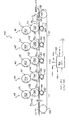
図1A及び1Bは、受け部材にマルチカラートナー画像を印刷するために適切である例示としての静電写真印刷エンジン又はプリンタ装置の部分を模式的に示す側面図である。本発明の一実施形態は、所謂、タンデム構成に構成された単色画像印刷アセンブリ又はモジュールM1乃至M5を有する静電写真エンジンを用いる印刷に関するが、本発明においては、3つ、4つ、5つ又は6つ以上のカラーが単独の受け部材において組み合わされることが可能であることが意図されている。本発明は、形成された画像がまた、電子写真ライタを用いて生成され、それ故、本発明の装置は、広義に、静電写真複写プリンタ装置と呼ばれている。その広い解釈で、本発明においては、他の処理がマルチカラー画像を生成するように用いられることが可能であることが意図されている。 1A and 1B are side views that schematically illustrate portions of an exemplary electrostatographic printing engine or printer device that are suitable for printing a multi-color toner image on a receiving member. One embodiment of the present invention relates to printing using an electrophotographic engine having a so-called tandem monochromatic image printing assembly or modules M1-M5, but in the present invention three, four, five Or it is contemplated that more than six collars can be combined in a single receiver. In the present invention, the formed image is also generated using an electrophotographic writer, so the apparatus of the present invention is broadly referred to as an electrostatographic copying printer apparatus. With its broad interpretation, it is contemplated in the present invention that other processes can be used to generate a multicolor image.
図1Aにおいては、例示としての静電写真プリンタ装置100は、複数のタンデム配置静電写真画像形成モジュール又は印刷アセンブリM1、M2、M3、M4及びM5を有する。それらのモジュールM1乃至M4の各々は、それらのモジュールを通って成功裏に移動される受け部材への転写のための単色トナー画像を生成する。モジュールM5は、下で詳細に説明するように、透明トナーのオーバーコートを備えるように用いられる。各々の受け部材は、それら5つのモジュールにおける一回の通過の間に、透明トナーのオーバーコートを有するマルチカラー画像を形成するように最大4つの単色トナー画像まで、位置合わせして転写することが可能である。本明細書で用いられているように、用語“マルチカラー”は、受け部材において形成される画像において、受け部材における種々の位置で、受け部材において他の色を形成するように組み合わされた複数の多原色の副集合の組み合わせを有し、その多原色は、それらの複数の多原色の副集合の少なくとも一部におけるプロセスカラーを形成するように関与することを意味する。特定の実施形態においては、M1は黒色(K)トナー色分離画像を形成し、M2は黄色(Y)トナー色分離画像を形成し、M3はマゼンタ色(M)トナー色分離画像を形成し、そしてM4はシアン色(C)トナー色分離画像を形成する。他の印刷アセンブリ又はモジュールは、受け部材における付加的な色を形成するように透明トナー印刷アセンブリ又はモジュールの前に付加されることが可能である。従って、付加モジュールは、赤色、青色、緑色又は他の5番目の又はそれ以上の色分離画像の一の色分離画像を形成することが可能である。4原色、シアン色、マゼンタ色、黄色及び黒色が、代表的なカラーのスペクトルを形成するようにそれらの副集合の種々の組み合わせに組み合わされ、複数の色を形成するために用いられるプロセス及び用いられる材料に依存してそれぞれの色域又は色範囲を有することが可能である。色域を付加することに加えて、5番目の色はまた、例えば、専用のロゴを作成するために、特定色トナー画像として用いられることが可能である。
In FIG. 1A, an exemplary
受け部材は、紙供給ユニット(図示せず)から供給され、それらのモジュールと通って搬送される。受け部材は、ローラ102、103の周囲で排出されて、駆動されるエンドレス搬送ウェブ101に付着される(例えば、好適には、結合されたタックダウンコロナ放電を介して静電気的に)。代替として、例えば、グリッパとしてよく知られている機械装置は、搬送ウェブ101に受け部材が付着するように用いられることが可能である。それぞれのモジュール(M1乃至M5)の各々は、光導電性像形成ローラ、中間転写部材ソー等及び転写バックアップローラを有する。従って、モジュールM1においては、黒色トナー分離画像が、光導電性造形性ローラ111(PC1)において生成され、転写アセンブリを通って移動する受け部材(R(n―1))に対して再び転写され、その転写アセンブリは、転写バックアップローラ113(TR1)により加圧ニップを形成する中間転写部材112(ITM1)を有する。同様に、モジュールM2、M3、M4及びM5はそれぞれ、PC2、ITM2、TR2(121、122、123);、PC3、ITM3、TR3(131、132、133);、PC4、ITM4、TR4(141、142、143);及び、PC5、ITM5、TR5(151、152、153)を有する。紙供給ユニットから到達した受け部材Rnは、第1モジュールM1の転写アセンブリへの後続のエントリのためのローラ102全体を通るように示され、先行する受け部材R(n−1)が示されている。同様に、受け部材R(n−2)、R(n−3)、R(n−4)及びR(n−5)が、モジュールM2、M3、M4及びM5の転写アセンブリのそれぞれを通って移動するように示されている。受け部材R(n−6)において形成された融着プリントは、加熱及び/又は加圧することにより受け部材に対して融着プリントを融着するように、図1Bに示しているフューザ60の方に、図示しているように移動する。クリーニングウェブ101についてのクリーニングアセンブリ(図示せず)が、典型的には、そのクリーニングウェブを再使用することができるように備えられている。
The receiving members are supplied from a paper supply unit (not shown) and conveyed through these modules. The receiving member is ejected around the
電源ユニット105は、転写バックアップローラTR1、TR2、TR3、TR4及びTR5のそれぞれに個別の転写電流を供給する。ロジック及び制御ユニット(LCU)230(図2を参照されたい)は1つ又はそれ以上のコンピュータを有し、プリンタ装置100に関連する種々のセンタからの信号に応答して、プリンタ装置の種々の成分及びプロセス制御パラメータを制御するようにそれぞれの成分に対してタイミング及び制御信号を供給する。即ち、LCU230はマイクロプロセッサと、LCU230により実行可能である適切なテーブル及び制御ソフトウェアとを有する。制御ソフトウェアは、好適には、LCU230に関連するメモリに記憶される。プリンタ装置に関連するセンサは、プリンタ装置のプロセス要素に関連するタイミング及び制御信号を生成する、又はそのタイミング及び制御信号に対して応答する。それらのセンサに応答して、LCU230は、プリンタ装置100の動作パラメータを調節する、又は、一般に、それらの動作パラメータをノミナル化する及び/又は最適化する。
The
カラー印刷モジュールM1乃至M5の代表的な一のカラー印刷モジュールが示されている図2を参照するに、プリンタ装置100の各々のカラー印刷モジュールは、それぞれの単色調画像を生成する複数の静電写真画像形成サブシステムを有する。代表のモジュール200には、画像形成シリンダの形で示されている光導電性画像形成部材205の表面206を均一に静電気的に帯電させる一次帯電サブシステム210と、それぞれの色に潜像静電色スペクトル画像を形成するように光導電性画像形成部材205を露光することにより均一な静電エネルギーを画像様変調する露光サブシステムと、それぞれの色のトナーにより画像様露光光導電性画像形成部材205の色調を変える現像サブシステム225と、合成マルチカラー画像を形成するように重ね合わせてそれぞれの色調合わせされた色分離画像238を受ける受け部材(第2転送ニップ202へのエントリに先行して示されている受け部材236、及び色調合わせされた色分離画像の転写に後続して示されている受け部材237)に、中間転写部材から第2転写ニップを介して、及び中間転写部材215の表面216に対する転写ニップ201を介して光導電性画像形成部材205から、それぞれの色分離画像を転写するための中間転写部材215と、を有する。受け部材に対する転写は、電源240からバックアップローラ235に供給される電場により影響される。印刷アセンブリの第5モジュールM5は、選択された特定の色を有する同様の種類のトナーを有することが可能である又は欠けている顔料(透明トナー)であることが可能であることを除いて、他のモジュールと実質的に同等である。
Referring to FIG. 2 in which a representative color printing module of the color printing modules M1 to M5 is shown, each color printing module of the
それぞれの色分離画像の転写、それぞれの印刷サブシステム又はモジュールの各々からの転写、及び、例えば、受け部材に対して色分離画像により形成されたマルチカラー画像に対する透明トナーオーバーコートの転写に後続して、そのような受け部材は、受け部材にマルチカラートナー及び透明トナーオーバーコート“画像”を融着する又は少なくとも加えるように、融着サブシステムの方に進められる。制御のために備えられる付加装置、例えば、均一な静電荷を測定する計器211、及び表面206上の非画像領域にときどき形成される潜像パッチのパッチ領域内のポスト露光表面電位を測定する計器212が、種々のモジュール要素の周囲に備えられることが可能である。プリンタ装置に関する更なる詳細については、2003年8月19日に公開された、Peter S.Alexandrovich等による米国特許第6,608,641号明細書にも記載されている。
Subsequent to the transfer of the respective color separation image, the transfer from each of the respective printing subsystems or modules, and the transfer of the transparent toner overcoat to, for example, a multicolor image formed by the color separation image on the receiving member. Thus, such a receiving member is advanced toward the fusing subsystem to fuse or at least add the multi-color toner and transparent toner overcoat "image" to the receiving member. Additional devices provided for control, such as an
プリンタ装置に関連する種々のセンサからの入力信号を受け入れ、チャージャ210、露光サブシステム220(例えば、LEDライタ)及びそれらのモジュールの現像サブシステム225に制御信号を送信する主LCU230は複数の色印刷モジュールの各々に関連付けられている。各々のモジュールはまた、プリンタ装置の主LCU230に結合されたそれぞれの制御器を有することが可能である。
The
各々の受け部材に対する重ね合わせ関係における3色の、4色の又はそれ以上の色トナー分離画像及び透明トナーオーバーコート画像の転写に後続して、受け部材は、その場合、搬送ウェブ101(図1Aを参照されたい)からデタックされ、受け部材に乾式トナー画像を融着する又は固定するように融着アセンブリ60に対して矢印B(図1B)で示す方向に送られる。搬送ウェブ101は、その場合、2つの表面を清浄にして電荷を供給することにより再使用のために再条件付けされ、そのことにより、搬送ウェブの対向する2つの基板において電荷が中和される。
Subsequent to the transfer of the three, four or more color toner separated images and the transparent toner overcoat image in a superimposed relationship with each receiving member, the receiving member then has a conveying web 101 (FIG. 1A). And is sent to the
静電画像は、それぞれの露光サブシステム220により光導電性部材205を担持する潜像に着色マーキング粒子を付けることにより現像され、その現像サブシステム225は、SPD(小粒子乾式)露光器を好適に用いる。複数の露光サブシステム225の各々は、それぞれの潜像を現像するように、適切なそれぞれの電圧によりそれぞれ電気的にバイアスされ、その電圧は、1つの電源により又は個別の電源(図示せず)により供給されることが可能である。好適には、それぞれの現像器は、トナーマーキング粒子及び磁性担持粒子を有する2つの構成要素を有する現像器である。各々の色の現像サブシステム225は、色調合わせのためにそれぞれ関連付けられる着色トナーマーキング粒子の特定の色を有する。従って、4つのモジュール、即ち、M1乃至M4の各々は、それぞれの光導電性部材205に異なる色のマーキング粒子画像を生成する。代替として、現像器は単独構成要素を有する現像器であることが可能である。カラートナーが湿式現像器に各々関連付けられることが可能であることがまた、意図されている。下で更に詳述しているように、透明トナー現像アセンブリは、着色トナーを堆積する他のモジュールの方式と同様の方式でモジュールM5が動作するように、着色現像器アセンブリの1つについて置き換えられることが可能であるが、透明トナーモジュールの現像アセンブリは、カラー現像アセンブリのトナーマーキング粒子と同様であるが、トナー内に組み込まれた着色材料なしで、それぞれ関連付けられるトナー粒子を有する。
The electrostatic image is developed by applying colored marking particles to the latent image carrying the
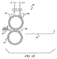
図1Bを参照するに、トナー画像担持受け部材は、加熱及び/又は加圧によりそれぞれの受け部材にトナー粒子を固定する、又は少なくとも付着する融着アセンブリ60に順次搬送される。特に、融着アセンブリ60は、加熱された融着ローラ62及び対向する加圧ローラ64を有し、それらの間には融着ニップ66を有する。融着アセンブリ60はまた、融着ローラ62に剥離液、例えば、シリコーンオイルを付着させる、一般指定された剥離液塗布サブアセンブリを有する。剥離液は、実質的にトナー粒子がフューザローラ62に付着しないようにする。
Referring to FIG. 1B, the toner image bearing receiving members are sequentially conveyed to a fusing
融着画像(又は、少なくとも付着した画像)を担持する受け部材は、透明トナーオーバーコートが供給されるようになっている場合に必要となる補助フューザ又は光沢アセンブリ等の何れかの適切な出力アセンブリへの経路に沿って融着アセンブリ60から搬送される。
The receiving member carrying the fused image (or at least the deposited image) is any suitable output assembly such as an auxiliary fuser or gloss assembly that is required when a clear toner overcoat is to be supplied. From the
上記のように、ディジタル印刷システム、例えば、プリンタ装置100の現在のICCワークフローを用いる場合、選択されたプリンタプロファイルは、ディジタルソース文書の演色性に対して重要である。ディジタル印刷システムにおける受け部材の基板に関連するICCプロファイルは、採用された印刷プロセス及びその特定の基板の物理的特徴により制御される。更に、静電写真印刷プロセスにおいては、フューザの制御パラメータ、例えば、融着温度及び融着圧力は、印刷可能な色域にかなり影響する。従って、カスタムICCプロファイルと呼ばれる受け部材の基板に特有のプリンタICCプロファイルが、各々の選択された基板における適切な色再現性のために必要である。勿論、採用された色材の印刷プロセス及び/又は物理特性/スペクトル特性の何らかの修正は、全ての予め生成されたプリンタICCプロファイルに低い精度を与える又は時代遅れである。現行の粒子は、上記のカスタムプロファイル方法に比べて精度が低い、基板の物理的特徴に従ったユニバーサルICCプロファイルの集合を採用するようになっている。再現された色を測定することなく、基板の物理的特徴のみに依存する1つの基板にユニバーサルICCプロファイルを与えるために、この技術は、印刷プロセスの何れかの修正について適切に適応することができない。
As described above, when using the current ICC workflow of a digital printing system, eg,
従来技術は、例えば、受け部材の基板の複数の寄与(例えば、基板の種類、重量等)の集合に関連する一部のユーザ入力を提供してきたが、この技術は、用いられるようになっている実際の基板のフィードバック測定(心理物理的/主観的な又は測定による/客観的な)なしに行われるものである。従って、個々のユーザの好み(主観的な)は“ユニバーサル”人間のものとは異なる可能性があること、又は、一部の受け部材の基板の記述は、用いられる適切なユニバーサルプロファイルを提示するには十分でないことが考慮されていない。このことは、基板の種類等は、基板の成分の詳細まで、例えば、どの材料又は繊維が用いられているかまで調べず、それ故、例えば、フューザに対する関係における基板材料/組成の相互作用は考慮されていない。このことは、色差をもたらすユニバーサルからのドットゲイン差をもたらす可能性があり、換言すれば、有効なユニバーサルプロファイルの最適な選択をもたらさない可能性がある。 Although the prior art has provided some user input related to a collection of multiple contributions (eg, substrate type, weight, etc.) of the receiving member substrate, for example, this technology has become used. Without actual substrate feedback measurements (psychophysical / subjective or measurable / objective). Thus, individual user preferences (subjective) may differ from those of “universal” humans, or a description of the board of some receiving members presents the appropriate universal profile to be used. Is not taken into account. This means that the type of substrate, etc. does not examine the details of the components of the substrate, for example, which material or fiber is used, and therefore considers the substrate material / composition interaction in relation to the fuser, for example. It has not been. This can result in a dot gain difference from universal that results in a color difference, in other words, it may not result in an optimal selection of a valid universal profile.
上記の問題を克服するために、400個以上の基板に対して色の最小差を与える少数のユニバーサルプロファイルに分類された、400個以上の基板についての構築されたプロファイルを有するデータベースが与えられる。勿論、それらの400個以上の基板は支持されていて、複数のユニバーサルプロファイルのどの一のユニバーサルプロファイルをそれぞれの基板と共に用いるべきかを示すLUTが成し遂げられる。しかしながら、新しい基板(オリジナルの400以上の基板以外の)を処理するために、基準からのドットゲイン差等の同じ基板のタイプ(例えば、コーティングされた光沢)であるが基板の組成によりもたらされる潜在的な問題に対処するように主観的なユーザの好みのフィードバック及び客観的な測定のフィードバックを含むことにより、新しい方法論が効果を現す。 To overcome the above problems, a database with built profiles for 400 or more substrates is provided, sorted into a small number of universal profiles that give the smallest color difference for 400 or more substrates. Of course, those 400 or more substrates are supported, and an LUT is achieved that indicates which one of a plurality of universal profiles should be used with each substrate. However, to process new substrates (other than the original 400 or more substrates), the potential provided by the same substrate type (eg, coated gloss), but the composition of the substrate, such as the dot gain difference from the reference By including subjective user preference feedback and objective measurement feedback to address common problems, new methodologies are effective.
客観的な見通しにより、少数の重要な色(例えば、ドットゲイン差に対して最大の感度を有する)が、選択された受け部材の基板を用いて印刷され、測定が行われる。特定のカラープロファイルを構築するように、数百又は更に数千のパッチではなく、少数のパッチのみが測定されるため、時間は比較的短くなり、そのことは、生産性への最小の影響を有するプリンタの較正/線形化手順に更に統合されることが可能である。現状の基板に特有のICCプロファイルの全体的収集を解析することにより得られた重要な色の1つの集合を次に示す。 By objective perspective, a small number of important colors (eg, having the greatest sensitivity to dot gain differences) are printed and measured using the selected receiver substrate. Because only a small number of patches are measured, not hundreds or even thousands, to build a specific color profile, the time is relatively short, which has the least impact on productivity. It can be further integrated into a printer calibration / linearization procedure. One set of important colors obtained by analyzing the overall collection of ICC profiles specific to current substrates is shown below.

4色印刷モジュール及びプリンタ装置100の透明トナー印刷アセンブリM1乃至M5を通る受け部材の基板の1パスにより、紙、プラスチック、コーティングされた金属又は繊維材料であることが可能である、シートの形の受け部材の基板は、4色トナー分離画像と、その4色トナー分離画像上に形成される透明なコーティングとを受ける。典型的には、紙等の代表的な受け部材の基板の公称の融着のパラメータは、基板の厚さ及び/又は重量と、製造時の光沢仕上げ又は艶消し仕上げ等の表面特性とに依存する。融着に後続して、基板表面上に形成される画像は完成し、対向する面における他の画像の形成、複層の画像形成を除いて、この受け部材の基板についての更なる処理は必要ない。
In the form of a sheet, which can be paper, plastic, coated metal or fiber material, with one pass of the substrate of the receiving member through the four-color printing module and the transparent toner printing assemblies M1-M5 of the
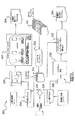
ユニバーサル受け部材基板プリンタICCプロファイルによる数の減少を可能にするように、本発明により提供されるユニバーサル基板プリンタICCプロファイル選択技術は、静的ユニバーサルプリンタICCプロファイルの集合と、主観的な評価又は客観的な色測定によるフィードバック情報とを組み合わせる。図3に示すフロー図を参照するに、全ての受け部材の基板についての有効なカスタムICCプロファイルが収集され(ステップ310)、カスタムICCプロファイルと各々の関連ユニバーサルプロファイルパラダイムとの間の全体的なエラーが最小化されるように、所定数のユニバーサルプロファイルパラダイムにクラスター化される(ステップ314)。即ち、ステップ314で得られたICCプロファイルの集合は、目的の受け部材の基板についてのカスタムICCプロファイルの全部の集合の性能を概算するための最適な選択である。所定の集合から目的の基板に対して1つのユニバーサルICCプロファイルを割り当てることは、視覚的評価又は客観的色測定からのフィードバック情報に基づき、種々の画像及びグラフィクスを含む試験スイート又は減少されたカラーパッチの集合が、目的の受け部材の基板に印刷される。視覚的な(即ち、主観による)カラープロファイル選択又は客観的な色測定の技術は、ステップ316においてユーザにより決定される。
The universal substrate printer ICC profile selection technique provided by the present invention provides a set of static universal printer ICC profiles and a subjective evaluation or objective so that the number can be reduced by universal receiver substrate printer ICC profiles. Combined with feedback information from various color measurements. Referring to the flow diagram shown in FIG. 3, valid custom ICC profiles for all receiving member substrates are collected (step 310), and an overall error between the custom ICC profile and each associated universal profile paradigm. Are clustered into a predetermined number of universal profile paradigms (step 314). That is, the set of ICC profiles obtained in
印刷プロセスの設定による色再現性及び目的の受け部材の基板の物理的特定の組み合わされた効果は、目的の基板に印刷されるときに、選択された主観点目的又は客観的目的に関して具現化される。主観的試験スイートは、主観的ユニバーサルプロファイル選択方法により全ての処理のユニバーサルICCプロファイルを介して目的の基板に印刷される(ステップ318)。ユーザ(即ち、顧客の観測者等)は印刷を評価し(ステップ320)、そのようなユーザにより最も好まれる試験スイートの具現化を確認する(ステップ322)。関連ユニバーサルICCプロファイルパラダイムが、その場合、特定の受け部材の基板についてのユニバーサルICCプロファイルとして選択される(ステップ324)。 The combined color reproducibility by the setting of the printing process and the physical specific combined effect of the substrate of the target receiving member are embodied with respect to the selected main or objective purpose when printed on the target substrate. The The subjective test suite is printed on the target substrate via the universal ICC profile of all processes by the subjective universal profile selection method (step 318). A user (ie, a customer observer) evaluates the print (step 320) and confirms the implementation of the test suite most preferred by such user (step 322). The relevant universal ICC profile paradigm is then selected as the universal ICC profile for the substrate of the particular receiving member (step 324).
他方、限定された数のカラーパッチを有する客観的目的について印刷され(ステップ326)、その後、適切な測色装置により測定される。カラーパッチの数は、カスタムICCプロファイルの全部プリンタプロファイルを生成するために必要な数に比べてかなり少なく、再現される客観的目的において、それらのカラーパッチは、基板差に関する色変動の重要な部分を得る(ステップ330)必要がある。ユニバーサルプロファイルパラダイム選択技術は、その場合、付加的なユーザ入力を伴わずに、目的の受け部材の基板についてのユニバーサルICCプロファイルを自動的に割り当てることができる。 On the other hand, it is printed for objective purposes with a limited number of color patches (step 326) and then measured by a suitable colorimetric device. The number of color patches is considerably less than that required to generate a full printer profile for a custom ICC profile, and for the objective to be reproduced, these color patches are an important part of the color variation related to substrate differences. (Step 330). The universal profile paradigm selection technique can then automatically assign a universal ICC profile for the target receiving member substrate without additional user input.
Claims (7)
受け部材の基板の物理的特性及び印刷プロセスの特徴に基づいて、カスタムカラープロファイルのデータベースを構築する段階;
クラスター化されたカスタムプロファイルからの受け部材の基板についての物理的特性に基づいて、ユニバーサルカラープロファイルの集合を決定する段階;
前記のユニバーサルカラープロファイルの集合から目的の受け部材の基板に1つのユニバーサルカラープロファイルを割り当てる段階;
前記割り当てられた1つのユニバーサルカラープロファイルを用いてマルチカラートナー画像を形成するように前記受け部材の基板における異なる画素位置に種々の色の組み合わせを形成するトナー顔料の少なくとも3つの異なる色のトナーにより前記受け部材の基板に前記マルチカラートナー画像を形成する段階;
前記形成されたマルチカラートナー画像に関して客観的フィードバック又は主観的フィードバックを与える段階;並びに
客観的フィードバック又は主観的フィードバックに基づいて、前記1つのユニバーサルカラープロファイルを修正する、又は異なるユニバーサルカラープロファイルを選択する段階;
を有する方法。 A method of forming a multicolor image on a substrate of a receiving member comprising:
Building a database of custom color profiles based on the physical characteristics of the substrate of the receiving member and characteristics of the printing process;
Determining a set of universal color profiles based on physical properties of the receiving member substrate from the clustered custom profile;
Assigning a universal color profile from the set of universal color profiles to a substrate of a target receiving member;
With toner pigments of at least three different colors forming various color combinations at different pixel locations on the substrate of the receiving member to form a multi-color toner image using the one universal color profile assigned Forming the multi-color toner image on a substrate of the receiving member;
Providing objective or subjective feedback on the formed multi-color toner image; and modifying the one universal color profile or selecting a different universal color profile based on the objective or subjective feedback Stage;
Having a method.
受け部材の基板の物理的特性及び印刷プロセスの特徴に基づいて、カスタムカラープロファイルのデータベースを構築する段階;
前記のユニバーサルカラープロファイルの集合から目的の受け部材の基板に1つのユニバーサルカラープロファイルを割り当てる段階;並びに
前記受け部材の基板における異なる画素位置において種々の色の組み合わせを形成するトナー顔料の少なくとも3つの異なる色のトナーにより、前記受け部材の基板におけるマルチカラートナー画像から得られた客観的フィードバック又は主観的フィードバックに基づいて、前記1つのユニバーサルカラープロファイルを修正する段階;
を有する方法。 A method for obtaining a color profile for forming a multicolor image on a substrate of a receiving member comprising:
Building a database of custom color profiles based on the physical properties of the substrate of the receiving member and characteristics of the printing process;
Assigning a universal color profile from the set of universal color profiles to a substrate of a target receiving member; and at least three different toner pigments that form various color combinations at different pixel locations on the receiving member substrate Modifying the one universal color profile with a color toner based on objective or subjective feedback obtained from a multi-color toner image on a substrate of the receiving member;
Having a method.
Applications Claiming Priority (2)
| Application Number | Priority Date | Filing Date | Title |
|---|---|---|---|
| US11/734,821 US7599634B2 (en) | 2007-04-13 | 2007-04-13 | Subjective and objective universal substrate printer ICC profile selection |
| PCT/US2008/004263 WO2008127553A1 (en) | 2007-04-13 | 2008-04-02 | Universal substrate printer icc profile selection |
Publications (2)
| Publication Number | Publication Date |
|---|---|
| JP2010524045A true JP2010524045A (en) | 2010-07-15 |
| JP2010524045A5 JP2010524045A5 (en) | 2012-05-24 |
Family
ID=39511025
Family Applications (1)
| Application Number | Title | Priority Date | Filing Date |
|---|---|---|---|
| JP2010503014A Pending JP2010524045A (en) | 2007-04-13 | 2008-04-02 | Universal PCB Printer ICC Profile Selection Method |
Country Status (4)
| Country | Link |
|---|---|
| US (1) | US7599634B2 (en) |
| EP (1) | EP2135440A1 (en) |
| JP (1) | JP2010524045A (en) |
| WO (1) | WO2008127553A1 (en) |
Families Citing this family (10)
| Publication number | Priority date | Publication date | Assignee | Title |
|---|---|---|---|---|
| JP2008294554A (en) * | 2007-05-22 | 2008-12-04 | Fuji Xerox Co Ltd | Image processing method and image forming apparatus |
| US8203737B2 (en) * | 2008-11-18 | 2012-06-19 | Xerox Corporation | Method and system for set-point sharing and purchasing |
| US8412055B2 (en) | 2010-05-14 | 2013-04-02 | Ricoh Production Print Solutions LLC | Automatic paper management and color profile utilization |
| JP5505366B2 (en) * | 2010-06-09 | 2014-05-28 | コニカミノルタ株式会社 | Profile set storage method, profile set storage program, profile set storage system, and color conversion processing apparatus |
| JP5699765B2 (en) * | 2010-06-15 | 2015-04-15 | 株式会社リコー | Image processing apparatus, image processing method, and image processing program |
| US8406673B2 (en) | 2010-12-10 | 2013-03-26 | Eastman Kodak Company | Rotatable member cleaner for electrophotographic printer |
| JP6319191B2 (en) * | 2015-05-28 | 2018-05-09 | 京セラドキュメントソリューションズ株式会社 | Image forming apparatus and program |
| CN107181892B (en) | 2016-03-11 | 2020-01-17 | 海德堡印刷机械股份公司 | Correction of color deviation in digital printing press |
| US10530970B2 (en) | 2016-09-02 | 2020-01-07 | Microsoft Technology Licensing, Llc | Automatic output metadata determination based on output device and substrate |
| JP2023141667A (en) * | 2022-03-24 | 2023-10-05 | コニカミノルタ株式会社 | Image forming apparatus, method for controlling image forming apparatus, and program |
Citations (3)
| Publication number | Priority date | Publication date | Assignee | Title |
|---|---|---|---|---|
| JP2005125714A (en) * | 2003-10-27 | 2005-05-19 | Canon Inc | Color imaging device and its control method |
| US20060285890A1 (en) * | 2005-06-17 | 2006-12-21 | Eastman Kodak Company | Method and apparatus for electrostatographic printing with generic color profiles and inverse masks based on receiver member characteristics |
| JP2007534512A (en) * | 2003-10-13 | 2007-11-29 | キクゼ・ソリューションズ・プライベイト・リミテッド | Method and apparatus for calibrating a color print engine |
Family Cites Families (11)
| Publication number | Priority date | Publication date | Assignee | Title |
|---|---|---|---|---|
| DE69103361T2 (en) * | 1990-03-30 | 1994-12-01 | Eastman Chem Co | METHOD FOR ALCOHOL / ESTER SEPARATION USING PROTECTED HYDROXYL GROUPS. |
| US5234783A (en) | 1991-12-16 | 1993-08-10 | Eastman Kodak Company | Method of selectively glossing toner images |
| US5995714A (en) | 1996-02-16 | 1999-11-30 | Eastman Kodak Company | Method for printer calibration |
| US6297205B1 (en) | 1999-08-30 | 2001-10-02 | Amway Corporation | Monohydric alcohol-free transparent moisturizing bar soap |
| US6563524B1 (en) * | 2001-12-12 | 2003-05-13 | Hewlett-Packard Development Company, L.P. | User-defined locally optimized color plane registration |
| US7068380B2 (en) * | 2001-12-21 | 2006-06-27 | Microsoft Corporation | Print media catalog service |
| JP4194363B2 (en) * | 2002-12-24 | 2008-12-10 | キヤノン株式会社 | Image forming apparatus |
| JP4612309B2 (en) * | 2004-01-07 | 2011-01-12 | セイコーエプソン株式会社 | Color conversion for color printers |
| JP4541860B2 (en) * | 2004-12-08 | 2010-09-08 | キヤノン株式会社 | Image forming apparatus and image forming method |
| US7236734B2 (en) | 2005-02-22 | 2007-06-26 | Eastman Kodak Company | Method and apparatus for electrostatographic printing with enhanced color gamut |
| JP4799206B2 (en) * | 2006-02-20 | 2011-10-26 | キヤノン株式会社 | Print control program, print control apparatus, and print control method |
-
2007
- 2007-04-13 US US11/734,821 patent/US7599634B2/en not_active Expired - Fee Related
-
2008
- 2008-04-02 WO PCT/US2008/004263 patent/WO2008127553A1/en active Application Filing
- 2008-04-02 JP JP2010503014A patent/JP2010524045A/en active Pending
- 2008-04-02 EP EP08742471A patent/EP2135440A1/en not_active Withdrawn
Patent Citations (3)
| Publication number | Priority date | Publication date | Assignee | Title |
|---|---|---|---|---|
| JP2007534512A (en) * | 2003-10-13 | 2007-11-29 | キクゼ・ソリューションズ・プライベイト・リミテッド | Method and apparatus for calibrating a color print engine |
| JP2005125714A (en) * | 2003-10-27 | 2005-05-19 | Canon Inc | Color imaging device and its control method |
| US20060285890A1 (en) * | 2005-06-17 | 2006-12-21 | Eastman Kodak Company | Method and apparatus for electrostatographic printing with generic color profiles and inverse masks based on receiver member characteristics |
Also Published As
| Publication number | Publication date |
|---|---|
| US7599634B2 (en) | 2009-10-06 |
| EP2135440A1 (en) | 2009-12-23 |
| WO2008127553A1 (en) | 2008-10-23 |
| US20080253783A1 (en) | 2008-10-16 |
Similar Documents
| Publication | Publication Date | Title |
|---|---|---|
| JP2010524045A (en) | Universal PCB Printer ICC Profile Selection Method | |
| US7340208B2 (en) | Method and apparatus for electrostatographic printing with generic color profiles and inverse masks based on receiver member characteristics | |
| JP4842969B2 (en) | Printing using a tandem color electrostatic printer | |
| US7236734B2 (en) | Method and apparatus for electrostatographic printing with enhanced color gamut | |
| US8358957B2 (en) | Selective printing of raised information by electrography | |
| US7548343B2 (en) | Color enhancement method and system | |
| US7783243B2 (en) | Enhanced fuser offset latitude method | |
| US8417171B2 (en) | Method and apparatus for printing embossed reflective images | |
| US7643175B2 (en) | Color print enhancement system with conversion of PCS encoded picture into photographic process confined PCS and correction for finish | |
| US9008527B2 (en) | Method for calibrating specialty color toner | |
| US10274883B1 (en) | Characterizing cross-track spacing variations in electrophotographic printer | |
| JP2013511070A (en) | Multi-pass electrophotographic printer sheet alignment | |
| US20220311903A1 (en) | Electrophotographic printing system including page rotations to reduce burn-in artifacts | |
| US11829084B2 (en) | Registration of white toner in an electrophotographic printer | |
| JP4502373B2 (en) | Image forming apparatus and control method thereof |
Legal Events
| Date | Code | Title | Description |
|---|---|---|---|
| A521 | Written amendment |
Free format text: JAPANESE INTERMEDIATE CODE: A523 Effective date: 20110323 |
|
| A621 | Written request for application examination |
Free format text: JAPANESE INTERMEDIATE CODE: A621 Effective date: 20110323 |
|
| A521 | Written amendment |
Free format text: JAPANESE INTERMEDIATE CODE: A523 Effective date: 20120322 |
|
| A131 | Notification of reasons for refusal |
Free format text: JAPANESE INTERMEDIATE CODE: A131 Effective date: 20120529 |
|
| A521 | Written amendment |
Free format text: JAPANESE INTERMEDIATE CODE: A523 Effective date: 20120827 |
|
| A02 | Decision of refusal |
Free format text: JAPANESE INTERMEDIATE CODE: A02 Effective date: 20130430 |