JP2010521052A - Lithium / iron disulfide battery and pretreatment method thereof - Google Patents
Lithium / iron disulfide battery and pretreatment method thereof Download PDFInfo
- Publication number
- JP2010521052A JP2010521052A JP2009553266A JP2009553266A JP2010521052A JP 2010521052 A JP2010521052 A JP 2010521052A JP 2009553266 A JP2009553266 A JP 2009553266A JP 2009553266 A JP2009553266 A JP 2009553266A JP 2010521052 A JP2010521052 A JP 2010521052A
- Authority
- JP
- Japan
- Prior art keywords
- battery
- cathode
- lithium
- electrolyte
- fes
- Prior art date
- Legal status (The legal status is an assumption and is not a legal conclusion. Google has not performed a legal analysis and makes no representation as to the accuracy of the status listed.)
- Withdrawn
Links
Images


Classifications
-
- H—ELECTRICITY
- H01—ELECTRIC ELEMENTS
- H01M—PROCESSES OR MEANS, e.g. BATTERIES, FOR THE DIRECT CONVERSION OF CHEMICAL ENERGY INTO ELECTRICAL ENERGY
- H01M6/00—Primary cells; Manufacture thereof
- H01M6/50—Methods or arrangements for servicing or maintenance, e.g. for maintaining operating temperature
-
- H—ELECTRICITY
- H01—ELECTRIC ELEMENTS
- H01M—PROCESSES OR MEANS, e.g. BATTERIES, FOR THE DIRECT CONVERSION OF CHEMICAL ENERGY INTO ELECTRICAL ENERGY
- H01M4/00—Electrodes
- H01M4/02—Electrodes composed of, or comprising, active material
- H01M4/36—Selection of substances as active materials, active masses, active liquids
- H01M4/38—Selection of substances as active materials, active masses, active liquids of elements or alloys
- H01M4/381—Alkaline or alkaline earth metals elements
- H01M4/382—Lithium
-
- H—ELECTRICITY
- H01—ELECTRIC ELEMENTS
- H01M—PROCESSES OR MEANS, e.g. BATTERIES, FOR THE DIRECT CONVERSION OF CHEMICAL ENERGY INTO ELECTRICAL ENERGY
- H01M4/00—Electrodes
- H01M4/02—Electrodes composed of, or comprising, active material
- H01M4/36—Selection of substances as active materials, active masses, active liquids
- H01M4/58—Selection of substances as active materials, active masses, active liquids of inorganic compounds other than oxides or hydroxides, e.g. sulfides, selenides, tellurides, halogenides or LiCoFy; of polyanionic structures, e.g. phosphates, silicates or borates
- H01M4/581—Chalcogenides or intercalation compounds thereof
- H01M4/5815—Sulfides
-
- H—ELECTRICITY
- H01—ELECTRIC ELEMENTS
- H01M—PROCESSES OR MEANS, e.g. BATTERIES, FOR THE DIRECT CONVERSION OF CHEMICAL ENERGY INTO ELECTRICAL ENERGY
- H01M6/00—Primary cells; Manufacture thereof
- H01M6/14—Cells with non-aqueous electrolyte
- H01M6/16—Cells with non-aqueous electrolyte with organic electrolyte
- H01M6/162—Cells with non-aqueous electrolyte with organic electrolyte characterised by the electrolyte
- H01M6/164—Cells with non-aqueous electrolyte with organic electrolyte characterised by the electrolyte by the solvent
-
- H—ELECTRICITY
- H01—ELECTRIC ELEMENTS
- H01M—PROCESSES OR MEANS, e.g. BATTERIES, FOR THE DIRECT CONVERSION OF CHEMICAL ENERGY INTO ELECTRICAL ENERGY
- H01M6/00—Primary cells; Manufacture thereof
- H01M6/50—Methods or arrangements for servicing or maintenance, e.g. for maintaining operating temperature
- H01M6/5088—Initial activation; predischarge; Stabilisation of initial voltage
-
- H—ELECTRICITY
- H01—ELECTRIC ELEMENTS
- H01M—PROCESSES OR MEANS, e.g. BATTERIES, FOR THE DIRECT CONVERSION OF CHEMICAL ENERGY INTO ELECTRICAL ENERGY
- H01M6/00—Primary cells; Manufacture thereof
- H01M6/14—Cells with non-aqueous electrolyte
- H01M6/16—Cells with non-aqueous electrolyte with organic electrolyte
- H01M6/162—Cells with non-aqueous electrolyte with organic electrolyte characterised by the electrolyte
- H01M6/166—Cells with non-aqueous electrolyte with organic electrolyte characterised by the electrolyte by the solute
-
- H—ELECTRICITY
- H01—ELECTRIC ELEMENTS
- H01M—PROCESSES OR MEANS, e.g. BATTERIES, FOR THE DIRECT CONVERSION OF CHEMICAL ENERGY INTO ELECTRICAL ENERGY
- H01M6/00—Primary cells; Manufacture thereof
- H01M6/14—Cells with non-aqueous electrolyte
- H01M6/16—Cells with non-aqueous electrolyte with organic electrolyte
- H01M6/162—Cells with non-aqueous electrolyte with organic electrolyte characterised by the electrolyte
- H01M6/168—Cells with non-aqueous electrolyte with organic electrolyte characterised by the electrolyte by additives
Abstract
リチウムを含むアノードと、二硫化鉄(FeS2)及び炭素粒子類を含むカソードと、を有する一次電池。前記電池は、コイン型電池の構造であることができ、又はアノードとカソードとを、それらの間のセパレータとともにらせん状に巻き付けて、それを電池ケーシングに挿入した後で電解質を添加することもできる。電解質は、エチレンカーボネート及びプロピレンカーボネートなどの有機環状カーボネートを包含し得る非水性溶媒混合物中に溶解されたリチウム塩を含んでいる。電池は、組み立てた後で、各工程中にパルス電流ドレインを少なくとも1サイクル有する少なくとも2つの同じ放電工程と、これら2つの工程の間に少なくとも1回の休止期間(工程休止)とを含む、2段階の前処理(前放電)プロトコルに付され、前記工程休止期間は、周囲温度よりも高い温度において、ある期間行われる。前処理によって電池性能が改善される。A primary battery having an anode containing lithium and a cathode containing iron disulfide (FeS 2 ) and carbon particles. The battery can be a coin-type battery structure, or the anode and cathode can be spirally wound with a separator between them and the electrolyte added after it is inserted into the battery casing. . The electrolyte includes a lithium salt dissolved in a non-aqueous solvent mixture that can include organic cyclic carbonates such as ethylene carbonate and propylene carbonate. The battery includes at least two identical discharge steps with at least one cycle of pulsed current drain in each step after assembly, and at least one pause period (step pause) between the two steps. Subjected to a step pre-treatment (pre-discharge) protocol, the process pause period is performed for a period of time at a temperature above ambient temperature. Pretreatment improves battery performance.
Description
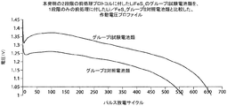
本発明は、リチウムを含むアノードと二硫化鉄を含むカソードとを有する一次電池の前処理方法に関する。新しい電池を、パルス放電工程の後、高温での休止工程に付し、好ましくは第2のパルス放電工程に付すことにより、電池が前処理されて、電池性能が改善される。 The present invention relates to a pretreatment method for a primary battery having an anode containing lithium and a cathode containing iron disulfide. By subjecting the new battery to a high temperature pause process after the pulse discharge process, and preferably to a second pulse discharge process, the battery is pretreated to improve battery performance.
リチウムアノードを有する一次(非充電式)電気化学電池類は知られており、及び幅広く商業的に利用されている。アノードは、本質的にリチウム金属から構成されている。かかる電池類は、典型的に、二酸化マンガンと、非水性溶媒中に溶解されたリチウム塩、例えば、トリフルオロメタンスルホン酸リチウム(LiCF3SO3)を含む電解質とを含むカソードを有する。これら電池類は、当該技術分野では一次リチウム電池類(一次Li/MnO2電池類)と呼ばれており、一般には、充電できるように意図されておらず、すなわち、それらは放電した後、廃棄するように意図されている。リチウム金属アノード類を有するが、様々なカソード類を有する、代替の一次リチウム電池類も知られている。かかる電池類は、例えば、二硫化鉄(FeS2)を含むカソード類を有しており、Li/FeS2電池類と呼ばれている。二硫化鉄(FeS2)はまた、黄鉄鉱としても知られている。Li/MnO2電池類又はLi/FeS2電池類は、典型的に円筒形電池類の形状、通常は単3サイズの電池又は2/3A型のLi/MnO2電池である。Li/MnO2電池類は、従来のZn/MnO2アルカリ電池類の二倍の約3.0ボルトの電圧を有し、そしてまた、アルカリ電池類のエネルギー密度よりも高いエネルギー密度(電池体積1cm3当たりのワット−時)をも有する。Li/FeS2電池類は、約1.2〜1.5ボルトの電圧(新品)を有し、これは従来のZn/MnO2アルカリ電池とほぼ同じである。にもかかわらず、Li/FeS2電池のエネルギー密度(電池体積1cm3当たりのワット−時)はまた、同等の大きさのZn/MnO2アルカリ電池よりも非常に高い。リチウム金属の理論比容量は、高めの3861.7ミリアンペア−時/グラムと高く、及びFeS2の理論比容量は893.6ミリアンペア−時/グラムである。FeS2の理論容量値は、1個のFeS2当たり4個のLiからの4個の電子の移動に基づいており、鉄元素Feと2個のLi2Sとの反応生成物をもたらす。すなわち、4個の電子のうち2個は、FeS2中のFe+2の価数状態をFeへと低下させ、そして残りの2個の電子が、硫黄の価数をFeS2中の−1からLi2S中の−2へと低下させる。
Primary (non-rechargeable) electrochemical cells having a lithium anode are known and widely used commercially. The anode is essentially composed of lithium metal. Such batteries typically have a cathode that includes manganese dioxide and an electrolyte that includes a lithium salt dissolved in a non-aqueous solvent, for example, lithium trifluoromethanesulfonate (LiCF 3 SO 3 ). These batteries are referred to in the art as primary lithium batteries (primary Li / MnO 2 batteries) and are generally not intended to be rechargeable, ie they are discharged and discarded. Is intended to be. Alternative primary lithium batteries having lithium metal anodes but various cathodes are also known. Such batteries have, for example, cathodes containing iron disulfide (FeS 2 ) and are called Li / FeS 2 batteries. Iron disulfide (FeS 2 ) is also known as pyrite. Li / MnO 2 batteries or Li / FeS 2 batteries are typically cylindrical batteries in shape, usually AA size batteries or 2 / 3A type Li / MnO 2 batteries. Li / MnO 2 batteries have a voltage of about 3.0 volts, twice that of conventional Zn / MnO 2 alkaline batteries, and also have an energy density higher than that of alkaline batteries (
Li/FeS2電池全体は、同じ大きさのZn/MnO2アルカリ電池よりも一層強力である。すなわち、所与の連続電流ドレインの場合、特に、200ミリアンペアを超える高い電流ドレインの場合、電圧vs時間プロファイルでは、Li/FeS2電池の電圧は、Zn/MnO2アルカリ電池ほど速く低下しない。これにより、Li/FeS2電池から得られるエネルギーは、同じ大きさのアルカリ電池で得られるエネルギーよりも高くなる。より高いエネルギー出力のLi/FeS2電池はまた、定電力(ワット)での連続放電に対するエネルギー(ワット−時)のグラフに更に直接的にはっきりと示されており、この場合、新しい電池は、最後まで0.01ワット程度〜5ワット程度の低い範囲の一定の連続電力で放電する。かかる試験では、電力ドレインは、0.01ワット〜5ワットの間で選択される一定の連続電力で維持される。(電池の電圧が放電中に低下するにつれて、負荷抵抗が徐々に低下し、電流ドレインが増大して、一定の定電力が保持される。)Li/FeS2電池に関するエネルギー(ワット−時)対電力(ワット)のグラフは、同じ大きさのアルカリ電池のグラフよりもかなり上方にある。にもかかわらず、これら電池(新品)の起動電圧はいずれも、ほぼ同じ、すなわち約1.2〜1.5ボルトの間である。 The entire Li / FeS 2 battery is more powerful than a Zn / MnO 2 alkaline battery of the same size. That is, for a given continuous current drain, especially for high current drains over 200 milliamps, the voltage vs time profile does not drop the voltage of the Li / FeS 2 battery as fast as the Zn / MnO 2 alkaline battery. Thereby, the energy obtained from the Li / FeS 2 battery is higher than the energy obtained from the alkaline battery of the same size. Higher energy output Li / FeS 2 batteries are also more clearly shown in the energy (watt-hour) graph for continuous discharge at constant power (watts), in which case the new battery is Discharge with a constant continuous power in the low range of about 0.01 watts to 5 watts until the end. In such tests, the power drain is maintained at a constant continuous power selected between 0.01 watts and 5 watts. (As the battery voltage decreases during discharge, the load resistance gradually decreases, the current drain increases and a constant constant power is maintained.) Energy (watt-hour) versus Li / FeS 2 battery The power (watt) graph is well above the graph for alkaline batteries of the same size. Nevertheless, the start-up voltages of these batteries (new) are almost the same, i.e. between about 1.2 and 1.5 volts.
したがって、Li/FeS2電池は、Li/FeS2電池が、従来のZn/MnO2アルカリ電池と互換的に利用でき、及び特により高い電力需要の場合には更に長い耐用年数を有するという点で、同じ大きさのアルカリ電池類、例えば、単4、単3、単2、又は単1サイズの電池、あるいはいずれかの他のサイズの電池よりも優れた利点を有している。同様に、一次(非充電式)電池であるLi/FeS2電池は、同じ大きさの充電式ニッケル水素電池類の代替品として利用でき、Li/FeS2電池とほぼ同じ電圧(新品)を有する。 Therefore, Li / FeS 2 cell, Li / FeS 2 cell, conventional Zn / MnO 2 alkaline cell and interchangeably available, and in particular in the case of a higher power demand in that it has a longer service life It has advantages over alkaline batteries of the same size, such as AAA, AA, AA, AA, or AA size batteries, or any other size battery. Similarly, Li / FeS 2 batteries, which are primary (non-rechargeable) batteries, can be used as replacements for rechargeable nickel metal hydride batteries of the same size, and have approximately the same voltage (new) as Li / FeS 2 batteries. .
カソード材料は、最初にスラリー混合物などの形態で調製されてもよく、それを従来のコーティング法によって金属基材上に容易にコーティングすることができる。電池に添加される電解質は、必要な電気化学反応類を、所望の高い電力範囲に亙って効率良く引き起こすことができる、Li/FeS2系にとって好適な非水電解質でなければならない。電解質は、良好なイオン導電性を示さなければならず、そしてまた、未放電の電極材料類(アノード及びカソード)やその結果得られる放電生成物に対しても十分に安定でなければならない。これは、電解質と電極材料(放電済みのもの又は未放電のもののどちらでも)との間の望ましくない酸化/還元反応が、それ故に電解質を徐々に汚染して、その有効性を軽減するか又は過剰にガスを発生させる可能性があるためである。この結果、壊滅的な電池の故障が生じる可能性がある。そのため、Li/FeS2電池中で使用される電解質は、必要な電気化学反応類を促進することに加えて、更には放電済み及び未放電の電極材料に対しても安定でなければならい。 The cathode material may first be prepared in the form of a slurry mixture or the like, which can be easily coated onto a metal substrate by conventional coating methods. The electrolyte added to the battery must be a suitable non-aqueous electrolyte for the Li / FeS 2 system that can efficiently cause the required electrochemical reactions over the desired high power range. The electrolyte must exhibit good ionic conductivity and must also be sufficiently stable against undischarged electrode materials (anode and cathode) and the resulting discharge products. This is because undesirable oxidation / reduction reactions between the electrolyte and the electrode material (either discharged or undischarged) can therefore gradually contaminate the electrolyte, reducing its effectiveness, or This is because gas may be generated excessively. This can result in catastrophic battery failure. Therefore, the electrolyte used in the Li / FeS 2 battery must be stable against discharged and undischarged electrode materials in addition to promoting the necessary electrochemical reactions.
一次リチウム電池類は、フラッシュ付きのデジタルカメラ類用の電源として利用されており、個々のアルカリ電池類で供給されるよりも高い電力要求量で作動する必要がある。一次リチウム電池類は、従来、リチウムシートから形成されたアノードと、導電性金属基材(カソード基材)上のFeS2を含むカソード活物質のコーティングから形成されたカソードと、それらの間の電解質透過性セパレータ材料のシートと、を含む電極複合体から形成されている。電極複合体は、例えば、米国特許第4,707,421号に示されているように、らせん状に巻き付けて、電池ケーシングに挿入されていてよい。Li/FeS2電池のためのカソードコーティング混合物は、米国特許第6,849,360号に記載されている。アノードシートの一部は、典型的には電池ケーシングと電気的に接続されて、電池の負端子を形成する。電池は、ケーシングから絶縁されたエンドキャップで閉じられている。カソードシートは、電池の正端子を形成するエンドキャップと電気的に接続することができる。ケーシングは、典型的にはエンドキャップの周縁部を覆うように曲げて、ケーシングの開口端部を密封する。 Primary lithium batteries are used as power sources for digital cameras with flash and need to operate at higher power requirements than are supplied by individual alkaline batteries. Primary lithium batteries conventionally include an anode formed from a lithium sheet, a cathode formed from a coating of a cathode active material comprising FeS 2 on a conductive metal substrate (cathode substrate), and an electrolyte therebetween. And a sheet of permeable separator material. The electrode composite may be spirally wound and inserted into the battery casing, for example, as shown in US Pat. No. 4,707,421. A cathode coating mixture for Li / FeS 2 batteries is described in US Pat. No. 6,849,360. A portion of the anode sheet is typically electrically connected to the battery casing to form the negative terminal of the battery. The battery is closed with an end cap insulated from the casing. The cathode sheet can be electrically connected to an end cap that forms the positive terminal of the battery. The casing is typically bent over the peripheral edge of the end cap to seal the open end of the casing.
Li/FeS2電池中のアノードは、銅などの金属基材の上にリチウム層を積層することによって形成することができる。ただし、アノードは、基材を全く用いずにリチウムのシートから形成されてもよい。 The anode in a Li / FeS 2 battery can be formed by laminating a lithium layer on a metal substrate such as copper. However, the anode may be formed from a lithium sheet without using any substrate.
一次Li/FeS2電池類に使用される電解質は、「有機溶媒」中に溶解された「リチウム塩」から典型的に形成された非水有機電解質である。「有機電解質」としては、有機溶媒中に溶解されたリチウム塩(又は他の塩)を含む電解質が挙げられるが、これに限定されない。Li/FeS2一次電池類用の電解質に用いることができる代表的なリチウム塩類は、米国特許第5,290,414号及び同第6,849,360(B2)号にも記されており、例えば、トリフルオロメタンスルホン酸リチウム、LiCF3SO3(LiTFS);リチウムビストリフルオロメチルスルホニルイミド、Li(CF3SO2)2N(LiTFSI);ヨウ化リチウム、LiI;臭化リチウム、LiBr;テトラフルオロホウ酸リチウム、LiBF4;六フッ化リン酸リチウム、LiPF6;六フッ化ヒ酸リチウム、LiAsF6;Li(CF3SO2)3Cのような塩類、及び様々な混合物が挙げられる。 The electrolyte used in primary Li / FeS 2 cells is a non-aqueous organic electrolyte typically formed from a “lithium salt” dissolved in an “organic solvent”. “Organic electrolyte” includes, but is not limited to, an electrolyte containing a lithium salt (or other salt) dissolved in an organic solvent. Representative lithium salts that can be used in electrolytes for Li / FeS 2 primary batteries are also described in US Pat. Nos. 5,290,414 and 6,849,360 (B2), For example, lithium trifluoromethanesulfonate, LiCF 3 SO 3 (LiTFS); lithium bistrifluoromethylsulfonylimide, Li (CF 3 SO 2 ) 2 N (LiTFSI); lithium iodide, LiI; lithium bromide, LiBr; tetrafluoro Examples include lithium borate, LiBF 4 ; lithium hexafluorophosphate, LiPF 6 ; lithium hexafluoroarsenate, LiAsF 6 ; salts such as Li (CF 3 SO 2 ) 3 C, and various mixtures.
一次Li/FeS2電池類のための電解質類用の有機溶媒類に関して使用できる、当該技術分野で参照されるいくつかの有機溶媒類の例は、次のとおりである:プロピレンカーボネート(PC)、エチレンカーボネート(EC)、ブチレンカーボネート(BC)、ジメトキシエタン(DME)、エチルグライム、ジグライム、及びトリグライム、ジメトキシプロパン(DMP)、ジオキソラン(DIOX)、3,5−ジメチルイソキサゾール(DMI)、テトラヒドロフラン(THF)、ジエチルカーボネート(DEC)、エチレングリコールサルファイト(EGS)、ジオキサン、ジメチルスルフェート(DMS)、3−メチル−2−オキサゾリドン、及びスルホラン(SU)、並びに様々な混合物。(例えば、米国特許第5,290,414号及び米国特許第6,849,360(B2)号を参照のこと。) Examples of some organic solvents referred to in the art that can be used in connection with organic solvents for electrolytes for primary Li / FeS 2 batteries are: propylene carbonate (PC), Ethylene carbonate (EC), butylene carbonate (BC), dimethoxyethane (DME), ethyl glyme, diglyme, and triglyme, dimethoxypropane (DMP), dioxolane (DIOX), 3,5-dimethylisoxazole (DMI), tetrahydrofuran (THF), diethyl carbonate (DEC), ethylene glycol sulfite (EGS), dioxane, dimethyl sulfate (DMS), 3-methyl-2-oxazolidone, and sulfolane (SU), and various mixtures. (See, for example, US Pat. No. 5,290,414 and US Pat. No. 6,849,360 (B2).)
米国特許第5,290,414号には、特に、FeS2電池類に有益な電解質の利用が報告されおり、電解質は、非環状(環状ではない)エーテル系溶媒と混合してジオキソランを含む溶媒中に溶解されたリチウム塩を含む。参照されているような非環状(環状ではない)エーテル系溶媒は、ジメトキシエタン、エチルグライム、ジグライム、及びトリグライムであってもよく、1−2ジメトキシエタン(dimetoxyehtane)(DME)が好ましい。かかる溶媒混合物(類)中でイオン化可能な具体的なリチウム塩としては、LiCF3SO3(LiTFS)若しくはLi(CF3SO2)2N(LiTFSI)、又はこれらの混合物が挙げられる。共溶媒は、3,5−ジメチルイソキサゾール(DMI)、3−メチル−2−オキサゾリドン、プロピレンカーボネート(PC)、エチレンカーボネート(EC)、ブチレンカーボネート(BC)、及びスルホランから選択された。 The solvent No. 5,290,414, in particular, FeS has been reported the use of a beneficial electrolyte second battery such, the electrolyte comprising a non-cyclic (not cyclic) dioxolane is mixed with an ether solvent Contains lithium salt dissolved therein. The acyclic (non-cyclic) ethereal solvent as referred to may be dimethoxyethane, ethylglyme, diglyme, and triglyme, with 1-2 dimethoxyoxytane (DME) being preferred. Specific lithium salts that can be ionized in such solvent mixture (s) include LiCF 3 SO 3 (LiTFS) or Li (CF 3 SO 2 ) 2 N (LiTFSI), or mixtures thereof. The co-solvent was selected from 3,5-dimethylisoxazole (DMI), 3-methyl-2-oxazolidone, propylene carbonate (PC), ethylene carbonate (EC), butylene carbonate (BC), and sulfolane.
米国特許第6,849,360(B2)号には、Li/FeS2電池用の電解質が具体的に開示されており、この電解質には、1,3−ジオキソラン(DIOX)と、1,2−ジメトキシエタン(DME)と、少量の3,5ジメチルイソキサゾール(DMI)とを含む有機溶媒混合物に溶解されたヨウ化リチウム塩が含まれている。 US Pat. No. 6,849,360 (B2) specifically discloses an electrolyte for a Li / FeS 2 battery, which includes 1,3-dioxolane (DIOX), 1,2 -Lithium iodide salt dissolved in an organic solvent mixture containing dimethoxyethane (DME) and a small amount of 3,5 dimethylisoxazole (DMI).
したがって、いずれか1つ以上のリチウム塩類とともに使用するための特定の有機溶媒又は様々な有機溶媒類の混合物を選択してLi/FeS2電池用の好適な電解質を製造するのが困難であることは、上記の代表的な参考文献類から明らかであろう。このことは、リチウム塩類と有機溶媒類との多くの組み合わせが、Li/FeS2電池をもたらさず、全く使い物にもならないということではない。むしろ、リチウム塩類と有機溶媒類とのいかなる組み合わせを用いても形成される電解質を利用したかかる電池類に関する問題は、もたらされる問題が恐らくは極めて根本的であるため、前記電池の商業的な利用を実行不可能にするということである。リチウム電池の開発史からは、一般に、リチウム一次電池類、例えば、Li/MnO2若しくはLi/FeS2であれ、又は充電式リチウム電池若しくはリチウムイオン電池であれ、リチウム塩類と有機溶媒とのいかなる組み合わせによっても良好な電池、すなわち良好で信頼できる性能を示すものが得られないと予想され得ることは明らかである。 Therefore, it is difficult to select a specific organic solvent or a mixture of various organic solvents for use with any one or more lithium salts to produce a suitable electrolyte for Li / FeS 2 batteries. Will be clear from the representative references above. This does not mean that many combinations of lithium salts and organic solvents do not yield a Li / FeS 2 battery and are not useable at all. Rather, the problem with such batteries that utilize electrolytes formed using any combination of lithium salts and organic solvents is that the resulting problems are probably very fundamental, so the commercial use of said batteries is limited. It is to make it infeasible. From the development history of lithium batteries, generally any combination of lithium salts and organic solvents, whether lithium primary batteries, for example Li / MnO 2 or Li / FeS 2 , or rechargeable lithium batteries or lithium ion batteries. It can be expected that will not yield a good battery, ie one that exhibits good and reliable performance.
有利な電解質混合物と主張されている例として、上記参考文献には、従来のリチウム塩類と併用して有効な電解質を製造するために、ジオキソランを、非環状(環状ではない)エーテル系溶媒、好ましくは1,2−ジメトキシエタン(DME)と組み合わせて有利に利用することが記されている。ただし、ジオキソランには費用及び取り扱いの点で不都合がある。 As an example claimed to be an advantageous electrolyte mixture, the above references describe dioxolane as an acyclic (non-cyclic) ether solvent, preferably in order to produce an effective electrolyte in combination with conventional lithium salts. Is advantageously used in combination with 1,2-dimethoxyethane (DME). However, dioxolane has disadvantages in terms of cost and handling.
したがって、ジオキソランよりも費用効率が良くまた取り扱いも容易な、Li/FeS2電池の電解質用溶媒類を用いることが望ましい。かかる溶媒類は、環状有機カーボネート類、例えば、エチレンカーボネート(EC)及びプロピレンカーボネート(PC)から選択することができ、これらはジオキソランよりも安価で、貯蔵及び取り扱いが容易である。エチレンカーボネート(EC)及びプロピレンカーボネート(PC)を、単独で又は混合して、そして更にはジメトキシエタン(DME)と混合することにより、特に電解質用リチウム塩がLiCF3SO3(LITFS)を含む場合に、Li/MnO2電池類と関連して使用される電解質用の極めて好適な溶媒類が製造されている。(例えば、米国特許第6,443,999(B1)号を参照のこと。) Therefore, it is desirable to use solvents for electrolytes of Li / FeS 2 batteries that are more cost effective and easier to handle than dioxolane. Such solvents can be selected from cyclic organic carbonates such as ethylene carbonate (EC) and propylene carbonate (PC), which are cheaper than dioxolane and easy to store and handle. Especially when the lithium salt for electrolyte contains LiCF 3 SO 3 (LITFS) by mixing ethylene carbonate (EC) and propylene carbonate (PC) alone or in combination and further with dimethoxyethane (DME). In addition, very suitable solvents for electrolytes used in connection with Li / MnO 2 batteries have been produced. (See, for example, US Pat. No. 6,443,999 (B1).)
しかしながら、かかる電解質類及び電解質溶媒系類、すなわち、エチレンカーボネート(EC)溶媒とプロピレンカーボネート(PC)溶媒とを含むものを用いた実験では、Li/MnO2電池類には有効だが、それ自体をLi/FeS2電池と関連して用いると、欠陥がもたらされる。前記問題点の一つは、かかるエチレンカーボネート/プロピレンカーボネート電解質溶媒混合物が、リチウム表面の不動態化の問題を引き起こすか又は悪化させる傾向があることであり、この不動態化は通常、Li/FeS2電池の放電耐用期間中に少なくともある程度まで生じる。リチウムの不動態化は、アノード中のリチウム金属表面と、電解質、特に電解質溶媒との緩やかな反応の結果として、Li/FeS2電池内で放電中又は貯蔵中に生じる。不溶層がリチウム金属表面上に徐々に形成されて、それがリチウム金属表面を不動態化して、その反応性を低下させる傾向がある。かかる表面層は、他よりも多少弱体化しており、電池の放電中にリチウムアノード金属が関与する電気化学反応の速度を低下させ、それ故に、適切な電池性能を妨げる可能性がある。 However, experiments using such electrolytes and electrolyte solvent systems, ie, those containing ethylene carbonate (EC) solvent and propylene carbonate (PC) solvent, are effective for Li / MnO 2 batteries, but as such When used in conjunction with Li / FeS 2 batteries, defects are introduced. One of the problems is that such ethylene carbonate / propylene carbonate electrolyte solvent mixtures tend to cause or exacerbate the problem of lithium surface passivation, which is usually a Li / FeS. 2 At least to some extent during the discharge life of the battery. Passivation of lithium, a lithium metal surface in the anode, the electrolyte, particularly as a result of the gradual reaction of the electrolyte solvent, resulting in the discharge or during storage in Li / FeS 2 cell. An insoluble layer is gradually formed on the lithium metal surface, which tends to passivate the lithium metal surface and reduce its reactivity. Such a surface layer is somewhat weaker than the others and can reduce the rate of electrochemical reactions involving the lithium anode metal during battery discharge, and therefore hinder proper battery performance.
Li/FeS2電池類用のエチレンカーボネート/プロピレンカーボネート電解質溶媒混合物の使用によってもたらされる別の問題は、かかる溶媒類が、初期電圧遅延(電圧降下)の問題を引き起こすか又はそれを悪化させる傾向があることであり、前記初期電圧遅延は、典型的には、電池の初期利用段階中又は初期利用期間中に生じる場合がある。かかる電圧降下は、電池の新たな利用期間の開始時に生じることがあり、電池の作動電圧を短期間で低下させることから、予期される一貫した信頼性のある電池性能の達成を妨げる可能性がある。電圧遅延は、通常、電池の内部抵抗の増加と関連しており、そして通常は、リチウムアノード上の不動態層の抵抗と関連している。 Another problem caused by the use of ethylene carbonate / propylene carbonate electrolyte solvent mixtures for Li / FeS 2 batteries is that such solvents tend to cause or exacerbate the initial voltage delay (voltage drop) problem. As such, the initial voltage delay may typically occur during the initial use phase of the battery or during the initial use period. Such a voltage drop can occur at the beginning of a new battery usage period and can reduce the operating voltage of the battery in a short period of time, thus preventing the achievement of the expected consistent and reliable battery performance. is there. Voltage delay is usually associated with an increase in the internal resistance of the cell and is usually associated with the resistance of the passive layer on the lithium anode.
したがって、Li/FeS2電池は、コスト効率の良い電解質を利用して製造することが望ましいが、それでもやはり前記電池には、リチウムアノードの低下した又は抑制された速度の不動態化が現れる。 Therefore, it is desirable to produce Li / FeS 2 batteries utilizing a cost effective electrolyte, but nevertheless, the batteries exhibit reduced or suppressed rate passivation of the lithium anode.
いかなる新たな放電期間の開始時でも、軽減された電圧遅延(電圧降下)発生を示す、Li/FeS2電池を製造することが望ましい。 It is desirable to produce a Li / FeS 2 battery that exhibits reduced voltage delay (voltage drop) occurrence at the beginning of any new discharge period.
特に、電解質が環状有機カーボネート溶媒、とりわけ環状グリコールカーボネート、望ましくは、例えば、限定されないが、エチレンカーボネート、プロピレンカーボネート、ブチレンカーボネート、及びこれらの混合物を含む、Li/FeS2電池用の電解質を製造することが望ましい。(これら前記カーボネート類は環状グリコールカーボネート類であるが、それらは従来、当該技術分野では、先に言及されたエチレンカーボネート、プロピレンカーボネート、及びブチレンカーボネートを指すと理解すべきである。) In particular, electrolytes for Li / FeS 2 batteries are produced where the electrolyte is a cyclic organic carbonate solvent, especially a cyclic glycol carbonate, desirably including, but not limited to, ethylene carbonate, propylene carbonate, butylene carbonate, and mixtures thereof. It is desirable. (These carbonates are cyclic glycol carbonates, which are conventionally understood in the art to refer to ethylene carbonate, propylene carbonate, and butylene carbonate referred to above.)
電解質がジオキソランを有しない溶媒を含んでいる、Li/FeS2電池用の電解質を製造することが望ましい。 It is desirable to produce an electrolyte for Li / FeS 2 batteries where the electrolyte contains a solvent that does not have dioxolane.
本発明は、アノードがリチウム金属を含む、リチウム一次電池類を目的する。リチウムは、少量の合金用金属、例えばアルミニウムと合金化されてリチウム合金を形成していてよく、典型的には合金用金属を約1重量%未満含んでいる。アノード活物質を形成するリチウムは、好ましくは薄い箔の形態である。電池は、カソード活物質であって、一般に「黄鉄鉱」として知られる二硫化鉄(FeS2)を含むカソードを有する。Li/FeS2電池は、ボタン型(コイン型)電池の形態であっても、平板状電池の形態であってもよい。望ましくは、電池は、アノードシートとカソード複合材料シートとを、それらの間のセパレータとともにらせん状に巻き付けた、らせん状の巻線形電池の形態であってもよい。カソードシートは、スラリー法を用いて導電性金属基材上に二硫化鉄(FeS2)粒子類を含むカソード混合物をコーティングすることで製造される。FeS2粒子類は、望ましくはエラストマー材料、好ましくはスチレン−エチレン/ブチレン−スチレン(SEBS)ブロックコポリマー、例えば、クレイトン(Kraton)G1651エラストマー(テキサス州ヒューストン(Houston)のクレイトン・ポリマーズ(Kraton Polymers))を用いて導電性金属基材に結合される。このポリマーは、皮膜形成剤であり、FeS2粒子類のみならずカソード混合物中の導電性炭素粒子添加物類に対しても良好な親和性と凝集特性とを有する。 The present invention is directed to lithium primary batteries wherein the anode comprises lithium metal. Lithium may be alloyed with a small amount of alloying metal such as aluminum to form a lithium alloy, and typically contains less than about 1% by weight of the alloying metal. The lithium forming the anode active material is preferably in the form of a thin foil. The cell has a cathode that is an active cathode material and includes iron disulfide (FeS 2 ), commonly known as “pyrite”. The Li / FeS 2 battery may be in the form of a button type (coin type) battery or in the form of a flat battery. Desirably, the battery may be in the form of a helically wound battery in which an anode sheet and a cathode composite sheet are spirally wound with a separator therebetween. The cathode sheet is manufactured by coating a cathode mixture containing iron disulfide (FeS 2 ) particles on a conductive metal substrate using a slurry method. FeS 2 particles desirably are elastomeric materials, preferably styrene-ethylene / butylene-styrene (SEBS) block copolymers, such as Kraton G1651 elastomer (Kraton Polymers, Houston, Texas). To be bonded to the conductive metal substrate. This polymer is a film forming agent and has good affinity and agglomeration properties not only for FeS 2 particles but also for conductive carbon particle additives in the cathode mixture.
本発明の態様では、カソードは、二硫化鉄(FeS2)粉末と導電性炭素粒子類と、結合剤材料と、溶媒とを含む、カソードスラリーから形成される。(用語「スラリー」は、本明細書で使用するとき、その通常の辞書の意味を有し、そしてそれ故に、固体粒子類を含む湿式混合物をも表すと理解されたい。)湿式カソードスラリーは、導電性基材の上、例えば、アルミニウム又はステンレス鋼のシートの上にコーティングされる。導電性基材は、カソード集電体として機能する。溶媒がその後蒸発すると、二硫化鉄材料と好ましくはカーボンブラックを包含する炭素粒子類とが互いに接着結合されて含まれている乾燥カソードコーティング混合物が残され、ただし、この乾燥コーティングは導電性基材と結合している。好ましいカーボンブラックはアセチレンブラックである。炭素は、所望により、そこに混入されたグラファイト粒子類を包含してよい。 In an aspect of the invention, the cathode is formed from a cathode slurry that includes iron disulfide (FeS 2 ) powder, conductive carbon particles, a binder material, and a solvent. (The term “slurry” as used herein has its usual dictionary meaning and is therefore understood to also represent a wet mixture comprising solid particles.) It is coated on a conductive substrate, for example on an aluminum or stainless steel sheet. The conductive substrate functions as a cathode current collector. Subsequent evaporation of the solvent leaves a dry cathode coating mixture containing iron disulfide material and carbon particles, preferably including carbon black, bonded together, provided that the dry coating is a conductive substrate. Is combined with. A preferred carbon black is acetylene black. The carbon may optionally include graphite particles incorporated therein.
湿式カソードスラリーを導電性基材の上にコーティングした後、コーティングされた基材をオーブンに入れて、溶媒が蒸発するまで高温で加熱する。得られる生成物は、二硫化鉄と炭素粒子類とを含む乾燥カソードコーティングであって、導電性基材に結合されている。乾燥基準で、カソードは、好ましくは4重量%以下の結合剤と、85〜95重量%のFeS2を含有する。固形分含有量、すなわち、湿式カソードスラリー中のFeS2粒子類と導電性炭素粒子類は、55〜70重量%である。カソードスラリーの粘度範囲は、約3500〜15000mPasである。(mPas=ミリニュートン×秒/m2)。リチウム金属を含むアノードと二硫化鉄を含むカソードとを、それらの間のセパレータとともに電池ハウジングに挿入してから、非水電解質を電池に加える。 After the wet cathode slurry is coated on the conductive substrate, the coated substrate is placed in an oven and heated at an elevated temperature until the solvent evaporates. The resulting product is a dry cathode coating comprising iron disulfide and carbon particles that are bonded to a conductive substrate. On a dry basis, the cathode preferably contains 4% by weight or less of the binder, of 85 to 95% by weight of FeS 2. The solid content, ie, FeS 2 particles and conductive carbon particles in the wet cathode slurry is 55 to 70% by weight. The viscosity range of the cathode slurry is about 3500-15000 mPas. (MPas = millinewton × second / m 2 ). An anode containing lithium metal and a cathode containing iron disulfide, together with a separator between them, are inserted into the battery housing before the non-aqueous electrolyte is added to the battery.
主な態様では、本発明は、リチウム又はリチウム合金アノードの表面上に作り出されるリチウムパッシベーション層の影響を軽減することを目的とする。(露出されたリチウム金属又はリチウム金属合金表面を有するリチウム電池類はいずれも、その上にコーティング又はパッシベーション層を生じることがあり、それによってリチウム表面の電気化学反応性を低下させて、電池の初期抵抗を増大させることがある。)リチウムパッシベーション層の有害な影響は、電池を新たに組み立てた後であるがそれが商業的に販売される前に、Li/FeS2電池を前処理(前放電)プロトコルに付すことによって軽減することができることが確認された。(用語「新たな」又は「新しい電池」は、本明細書で使用するとき、製造されたが未だ商業的に販売されていない電池に言及するものとする。) In a main aspect, the present invention aims to mitigate the effects of a lithium passivation layer created on the surface of a lithium or lithium alloy anode. (Any lithium batteries having an exposed lithium metal or lithium metal alloy surface may produce a coating or passivation layer thereon, thereby reducing the electrochemical reactivity of the lithium surface and resistance may be increased.) detrimental effects of lithium passivation layer, but before after the newly assembled battery to be sold it commercially, pretreating the Li / FeS 2 cell (predischarge It was confirmed that it can be mitigated by attaching to the protocol. (The term “new” or “new battery” as used herein shall refer to batteries that have been manufactured but not yet sold commercially.)
本発明の主な態様では、新しいLi/FeS2電池の前処理には、2段階の前放電プロトコルが含まれており、その場合、電池は、各工程において少なくとも1サイクルのパルス電流ドレインを有する少なくとも2つの別個の放電工程と、前記2つの放電工程間の少なくとも1つの休止期間(工程休止)とに付される。工程休止期間は、実際には、電池をある期間、周囲温度よりも高い温度(>21℃)で、典型的には約21℃〜70℃まで、好ましくは約40〜70℃までの高温、例えば約60℃で貯蔵しておく電池貯蔵期間である。工程休止(貯蔵)期間は、典型的には、約2時間〜24時間までの期間であってよい。好ましくは、第2の放電工程後にも、同様の工程休止(貯蔵)があり、その場合、電池は、周囲温度よりも高い温度(>21℃)、典型的には約21℃〜70℃まで、好ましくは約40〜70℃で、典型的には約2時間〜24時間までの期間で貯蔵される。 In the main aspect of the invention, the pre-treatment of the new Li / FeS 2 battery includes a two-stage pre-discharge protocol, in which case the battery has at least one cycle of pulsed current drain in each step. It is subjected to at least two separate discharge steps and at least one pause period (process pause) between the two discharge steps. The process pause period is actually a temperature higher than ambient temperature (> 21 ° C.) for a period of time, typically up to about 21 ° C. to 70 ° C., preferably about 40 to 70 ° C., For example, it is a battery storage period for storing at about 60 ° C. The process pause (storage) period may typically be a period of about 2 to 24 hours. Preferably, there is also a similar process pause (storage) after the second discharge step, in which case the battery is at a temperature above ambient temperature (> 21 ° C.), typically from about 21 ° C. to 70 ° C. Preferably, it is stored at about 40-70 ° C., typically for a period of about 2-24 hours.
したがって、一例として、前記2つの放電工程には、少なくとも1つの放電パルスであって、例えば、典型的には比較的短い時間、例えば、平均して約2〜20秒間の少なくとも1つの直流パルスを含む、少なくとも1回のパルスサイクルが含まれる。そのため、用語「パルス」又は「パルスドレイン」には、典型的に持続時間が約20秒(あるいはそれ以上)までの比較的短い突発的な電流ドレインが包含されるものとする。かかるパルスは、生じる場合、望ましくは約1〜50ミリアンペア/cm2の一定の又は可変の電流密度であってよく、そのため、典型的には、約1〜50ミリアンペア/cm2の平均電流密度を有する。(電流密度は、コイン型電池又はらせん状の巻線形電池のどちらにおいても、アノード表面と、それと対向するカソード表面との間の接合部分領域を流れる電流に相当する。)所望の電流密度でのパルスは、様々な方法で、例えば、定電流、定電圧、又は定電力で放電することによって達成することができる。好ましくは、2つの放電工程それぞれに、少なくとも2つの断続的なパルスがある。2つの放電工程それぞれにおけるパルスは、典型的には約1〜50ミリアンペア/cm2の平均電流密度を有する一定の又は可変の電流密度であってよい。2つの放電工程それぞれでは、各パルスの後に短い断続的なパルス停止が短期間、典型的には約10秒〜100秒間続いてよく、それによって1つのパルスサイクルが完成される。 Thus, as an example, the two discharge steps include at least one discharge pulse, for example, typically at least one DC pulse for a relatively short period of time, for example, about 2 to 20 seconds on average. Including at least one pulse cycle. As such, the term “pulse” or “pulse drain” is intended to encompass relatively short bursts of current drain, typically up to about 20 seconds (or more) in duration. Such pulses may occur, desirably may be a current density of constant or variable about 1 to 50 mA / cm 2, therefore, typically an average current density of about 1-50 mA / cm 2 Have. (The current density corresponds to the current flowing through the junction region between the anode surface and the opposing cathode surface in either a coin-type battery or a spiral wound battery.) The pulse can be achieved in various ways, for example by discharging at a constant current, a constant voltage, or a constant power. Preferably, there are at least two intermittent pulses in each of the two discharge steps. Pulse in each of the two discharge steps may typically be a current density of constant or variable with a mean current density of about 1-50 mA / cm 2. In each of the two discharge steps, each pulse can be followed by a short intermittent pulse stop for a short period, typically about 10 to 100 seconds, thereby completing one pulse cycle.
第1の放電工程は、単一のパルスサイクルを有していても、複数のパルスサイクルを有していてもよく、複数のパルスサイクルには、例えば、5個、10個、15個、20個以上の断続的なパルスのように典型的に約1〜100個の断続的なパルスと、各パルス間に典型的に10秒〜100秒の前記の短い断続的な停止とが含まれてよい。1つ以上のかかるパルスサイクル(パルスの後、断続的なパルス停止が続く)を含む第1の放電工程を終えると、電池は、工程休止(貯蔵)に付され、そこで、電池は、約21℃〜70℃、好ましくは約40〜70℃の温度に約2時間〜24時間曝露される。電池は、その後、少なくとも1つの新しいパルス電流ドレインを含む第2の放電工程に付される。しかしながら、第2の工程には、複数のパルスが包含されていてよく、これには例えば、第1の放電工程と同様に5個、10個、15個、20個以上のパルスのように典型的に約1〜100個の断続的なパルスとともに、これら断続的なパルスの間に10秒〜100秒の短い断続的な停止が含まれてよい。好ましくは、この第2の工程後に、電池は更に、約21℃〜70℃の温度である期間、好ましくは、約40〜70℃で典型的には約2〜48時間貯蔵される(工程休止)。本発明の前処理(前放電)プロトコルにおけるパルス放電全体では、電池の理論容量の約10%までが消費され得る。 The first discharge process may have a single pulse cycle or may have a plurality of pulse cycles. For the plurality of pulse cycles, for example, 5, 10, 15, 20 Typically about 1-100 intermittent pulses, such as more than one intermittent pulse, and the short intermittent stops typically between 10 and 100 seconds between each pulse. Good. Upon completion of the first discharge process including one or more such pulse cycles (followed by intermittent pulse stops after the pulse), the battery is subjected to process pause (storage), where the battery is about 21 It is exposed to a temperature of from C to 70 C, preferably from about 40 to 70 C for about 2 to 24 hours. The battery is then subjected to a second discharge step that includes at least one new pulsed current drain. However, the second step may include a plurality of pulses, which are typical of, for example, five, ten, fifteen, twenty or more pulses as in the first discharge step. Along with about 1 to 100 intermittent pulses, a short intermittent stop of 10 to 100 seconds may be included between these intermittent pulses. Preferably, after this second step, the battery is further stored for a period of about 21 ° C. to 70 ° C., preferably at about 40 ° C. to 70 ° C., typically for about 2 to 48 hours. ). The entire pulse discharge in the pre-treatment (pre-discharge) protocol of the present invention can consume up to about 10% of the theoretical capacity of the battery.
新しいLi/FeS2電池を本発明のかかる前処理プロトコルに付した場合、電池性能に顕著な改善があることが確認された。すなわち、電池は、所与の放電電流では、電池を本発明の前処理プロトコルに付さなかった場合よりも高い電圧プロファイルを維持する。これにより、結果として、本発明の前処理プロトコルに付したLiFeS2電池では、より高いエネルギー出力がもたらされる。改善された性能は、電池の形状又は構成(例えば、ボタン型電池又は巻線形の円筒形電池)に関わらず期待することができる。 When a new Li / FeS 2 battery was subjected to such a pretreatment protocol of the present invention, it was confirmed that there was a significant improvement in battery performance. That is, the battery maintains a higher voltage profile at a given discharge current than if the battery was not subjected to the pretreatment protocol of the present invention. This results in a higher energy output in the LiFeS 2 battery subjected to the pretreatment protocol of the present invention. Improved performance can be expected regardless of the shape or configuration of the battery (eg, button-type battery or wound cylindrical battery).
新しいLi/FeS2電池が付される本発明の前処理(前放電)プロトコルは、リチウムアノードの表面上に作り出されるリチウムパッシベーション層に対して軽減効果を発揮すると考えられる。本発明の前処理(前放電)プロトコルは、リチウムパッシベーション層を安定化し、更にその化学的性質をも変える場合があると考えられる。これにより、結果として、リチウムパッシベーション層の抵抗を低下させ及び電池の内部抵抗を下げて、電池性能を改善することができる。前処理プロトコルは、少なくとも1つのパルス放電サイクルを伴う放電工程の後に、周囲温度よりも高い温度での少なくとも1つの電池貯蔵期間(工程休止)を含んでおり、電解質及びカソードから不純物を取り除くのに役立つ場合もあるため、電解質及びカソード物質の有効性をも改善する。 The pre-treatment (pre-discharge) protocol of the present invention with a new Li / FeS 2 battery is believed to exert a mitigating effect on the lithium passivation layer created on the surface of the lithium anode. It is believed that the pre-treatment (pre-discharge) protocol of the present invention may stabilize the lithium passivation layer and also change its chemistry. Thereby, as a result, the resistance of the lithium passivation layer can be lowered and the internal resistance of the battery can be lowered to improve the battery performance. The pretreatment protocol includes a discharge process with at least one pulsed discharge cycle followed by at least one battery storage period (process pause) at a temperature higher than ambient temperature to remove impurities from the electrolyte and cathode. It may also be useful, thus improving the effectiveness of the electrolyte and cathode material.
本発明の主な態様では、リチウム/二硫化鉄電池用の所望の非水電解質には、有機溶媒中に溶解されたリチウム塩が含まれる。所望の電解質溶媒混合物には、環状有機カーボネート、好ましくは環状グリコールカーボネート、例えば、エチレンカーボネート、プロピレンカーボネート、又はブチレンカーボネート、及びこれらの混合物が、有機エーテル、好ましくはグリコールエーテル、望ましくは1,2−ジメトキシエタン(DME)と混合して含まれることが確認された。(ジメトキシエタンはまた、化学文献ではエチレングリコールジメチルエーテルとも記されており、化学式CH3OCH2CH2OCH3を有する。)(電解質溶媒はまた、ジメチルカーボネート及び/又はエチルメチルカーボネートを含んでいてもよい。)好ましくは、ヨウ素元素は電解質混合物に、それが電解質混合物の約0.01〜5重量%を構成する、好ましくは非水電解質混合物の約0.5重量%を構成するように添加される。(Li/FeS2電池類に関する、ヨウ素元素を非水電解質混合物類へ添加する望ましさは、2006年7月1日に出願された譲渡人に譲渡された米国特許出願番号11/479328に開示されている。) In the main aspect of the present invention, the desired non-aqueous electrolyte for a lithium / iron disulfide battery includes a lithium salt dissolved in an organic solvent. Desired electrolyte solvent mixtures include cyclic organic carbonates, preferably cyclic glycol carbonates such as ethylene carbonate, propylene carbonate, or butylene carbonate, and mixtures thereof, organic ethers, preferably glycol ethers, desirably 1,2- It was confirmed that it was mixed with dimethoxyethane (DME). (Dimethoxyethane is also described in the chemical literature as ethylene glycol dimethyl ether and has the chemical formula CH 3 OCH 2 CH 2 OCH 3. ) (The electrolyte solvent may also contain dimethyl carbonate and / or ethyl methyl carbonate. Preferably, elemental iodine is added to the electrolyte mixture so that it constitutes about 0.01 to 5% by weight of the electrolyte mixture, preferably about 0.5% by weight of the non-aqueous electrolyte mixture. The (The desirability of adding elemental iodine to non-aqueous electrolyte mixtures for Li / FeS 2 batteries is disclosed in commonly assigned US patent application Ser. No. 11 / 479,328, filed on Jul. 1, 2006. ing.)
好ましい電解質溶媒は、エチレンカーボネート(EC)(式C3H4O3)及びプロピレンカーボネート(PC)(式C4H6O3)及びと混合してジメトキシエタン(式C4H10O2)を含む。エチレンカーボネート及びプロピレンカーボネートは、環状有機カーボネート類である。エチレンカーボネートは、化学情報検索サービス機関(Chemical Abstracts Service)CAS番号96−49−1を有する。プロピレンカーボネートは、化学情報検索サービス機関(Chemical Abstracts Service)(CAS)の登録識別用のCAS番号108−32−7を有する。これら溶媒類についての基本的な特性データは、例えば、実用化学辞典(the Condensed Chemical Dictionary)、第10版、ゲスナー・G・ホーレイ(Gessner G. Hawley)改訂、ファン・ノストランド・ラインホールド・カンパニー(Van Nostrand Reinhold Company)で容易に入手可能である。更なる特性及び式のデータはまた、例えば、上記溶媒名であるエチレンカーボネート、プロピレンカーボネート(、並びにブチレンカーボネート)をグーグル(Google)の検索ウェブサイト:www.Google.comに入力することによっても入手可能である。 Preferred electrolyte solvents are ethylene carbonate (EC) (formula C 3 H 4 O 3 ) and propylene carbonate (PC) (formula C 4 H 6 O 3 ) and mixed with dimethoxyethane (formula C 4 H 10 O 2 ). including. Ethylene carbonate and propylene carbonate are cyclic organic carbonates. Ethylene carbonate has the Chemical Abstracts Service CAS number 96-49-1. Propylene carbonate has CAS number 108-32-7 for registration identification of Chemical Abstracts Service (CAS). The basic property data for these solvents are, for example, the Condensed Chemical Dictionary, 10th edition, Gessner G. Hawley revision, Van Nostrand Reinhold Company (Van Nostrand Reinhold Company). Additional property and formula data can also be found, for example, using the above solvent names ethylene carbonate, propylene carbonate (and butylene carbonate) on Google's search website: www. Google. It is also possible to obtain it by entering it in com.
好ましい電解質溶媒には、エチレンカーボネート(EC)とプロピレンカーボネート(PC)と混合したジメトキシエタン(DME)との混合物が含まれる。これら溶媒類はそれぞれ、FeS2による酸化に対して耐性を有し、そしてLi/FeS2系の放電生成物に対して安定である。かかる溶媒混合物は、結合剤材料の特性を不利に妨げない。例えば、かかる溶媒混合物は、エラストマー結合剤、例えば、クレイトン(Kraton)G1651スチレン−エチレン/ブチレン−スチレンブロックコポリマーとは、結合剤の特性を著しく妨害するほど十分には反応しない。好ましくは、電解質溶媒混合物は、ジメトキシエタン(DME)を約40〜98重量%、エチレンカーボネート(EC)を1〜30重量%、及びプロピレンカーボネート(PC)を1〜30重量%含む。電解質溶媒混合物は、ジオキソランを有しない場合があり、すなわち、検出可能な量のジオキソランを含有しない場合がある。電解質溶媒混合物は、本質的にはジオキソランを有しない、すなわち、ほんの微量のジオキソラン、例えば前記溶媒混合物の100ppm未満のジオキソラン、例えば50ppm未満のジオキソラン、例えば25ppm未満のジオキソランを含有する場合もある。かかる低濃度では、微量のジオキソランは特別な機能を全く果たさないと予想されよう。 Preferred electrolyte solvents include a mixture of ethylene carbonate (EC) and dimethoxyethane (DME) mixed with propylene carbonate (PC). Each of these solvents is resistant to oxidation by FeS 2 and is stable to Li / FeS 2 based discharge products. Such solvent mixtures do not adversely interfere with the properties of the binder material. For example, such solvent mixtures do not react sufficiently with elastomeric binders such as Kraton G1651 styrene-ethylene / butylene-styrene block copolymer to significantly interfere with the properties of the binder. Preferably, the electrolyte solvent mixture comprises about 40-98 wt% dimethoxyethane (DME), 1-30 wt% ethylene carbonate (EC), and 1-30 wt% propylene carbonate (PC). The electrolyte solvent mixture may not have dioxolane, i.e. may not contain a detectable amount of dioxolane. The electrolyte solvent mixture may be essentially free of dioxolane, that is, it may contain only trace amounts of dioxolane, such as less than 100 ppm dioxolane, such as less than 50 ppm dioxolane, such as less than 25 ppm dioxolane. At such low concentrations, trace amounts of dioxolane would be expected to perform no special function.
本発明のLi/FeS2電池に望ましい電解質混合物は、ジメトキシエタン(DME)とエチレンカーボネート(EC)とプロピレンカーボネート(PC)とを含む有機溶媒混合物中に溶解された、リチウム塩である化学式LiCF3SO3のトリフルオロメタンスルホン酸リチウム(LiTFS)及び/又は化学式Li(CF3SO2)2Nのリチウムビストリフルオロメチルスルホニルイミド(LiTFSI)を含むことが確認された。好ましい電解質混合物は、約75〜95重量%のジメトキシエタン(DME)と、2〜10重量%のエチレンカーボネート(EC)と、約3〜15重量%のプロピレンカーボネート(PC)とを含む有機溶媒混合物中に溶解された、約0.3モル濃度〜0.6モル濃度(0.3〜0.6モル/リットル)のLiCF3SO3(LiTFS)塩及び0.3モル濃度〜0.6モル濃度(0.3〜0.6モル/リットル)のLi(CF3SO2)2N(LiTFSI)塩と、0.25重量%のLiClO4と、0.5重量%のヨウ素元素とを含む電解質溶液であることが確認された。LiClO4は、任意であるが、それが電解質中に包含されていることが望ましい。というのも、それは、二硫化鉄を含むカソードコーティングが上にコーティングされたアルミニウム若しくはアルミニウム合金のグリッド又は基材において、防食防錆剤として作用するためである。ヨウ素元素(I2)は、望ましくは、Li/FeS2電池類用のかかる電解質混合物に添加される。Li/FeS2電池類用の、非水電解質混合物類にヨウ素元素を添加する望ましさは、2007年1月5日に出願された、譲渡人に譲渡された特許出願番号11/650,405に開示されている。ヨウ素の添加により、リチウムアノードの表面上に堆積するリチウムパッシベーション層の有害な影響が軽減されることが確認された。電解質中のヨウ素元素の存在は、リチウムパッシベーション層の化学的性質を変えることで、リチウムアノードの表面上のリチウムパッシベーション層の影響を軽減する、すなわち、その抵抗を低下させるのに役立つと考えられる。そのため、新しい電池に付される先に記した本発明の前処理プロトコルと、電解質中にヨウ素元素を包含することとはいずれも、ともにリチウムアノードの表面上のリチウムパッシベーション層の影響を軽減する配合効果を発揮すると思われる。これにより、結果として電池性能が改善される。非水電解質へのヨウ素元素の添加はまた、電圧遅延(電圧降下)の問題をも解決又は軽減し、そうでなければ、この電圧遅延は、環状の有機カーボネート溶媒類、例えば、エチレンカーボネート(EC)及び/又はプロピレンカーボネート(PC)を含む電解質を用いたLi/FeS2電池の新たな放電期間の開始時に生じるか又はより顕著である場合がある。 The preferred electrolyte mixture for the Li / FeS 2 battery of the present invention is the chemical formula LiCF 3 which is a lithium salt dissolved in an organic solvent mixture comprising dimethoxyethane (DME), ethylene carbonate (EC) and propylene carbonate (PC). It was confirmed to contain lithium trifluoromethanesulfonate (LiTFS) of SO 3 and / or lithium bistrifluoromethylsulfonylimide (LiTFSI) of the chemical formula Li (CF 3 SO 2 ) 2 N. A preferred electrolyte mixture is an organic solvent mixture comprising about 75-95% by weight dimethoxyethane (DME), 2-10% by weight ethylene carbonate (EC), and about 3-15% by weight propylene carbonate (PC). dissolved in, LiCF 3 SO 3 to about 0.3 molar to 0.6 molar concentration (0.3 to 0.6 mol / liter) (LiTFS) salt and 0.3 molar to 0.6 molar concentration and Li (CF 3 SO 2) 2 N (LiTFSI) salt (0.3 to 0.6 mole / liter), and LiClO4 0.25 wt%, an electrolyte containing a 0.5 weight percent elemental iodine It was confirmed to be a solution. LiClO 4 is optional, but desirably it is included in the electrolyte. This is because it acts as an anticorrosive rust inhibitor in an aluminum or aluminum alloy grid or substrate on which a cathode coating comprising iron disulfide is coated. Elemental iodine (I 2 ) is desirably added to such electrolyte mixtures for Li / FeS 2 batteries. The desirability of adding elemental iodine to non-aqueous electrolyte mixtures for Li / FeS 2 batteries is described in assignee-assigned patent application No. 11 / 650,405, filed Jan. 5, 2007. It is disclosed. It has been confirmed that the addition of iodine reduces the harmful effect of the lithium passivation layer deposited on the surface of the lithium anode. The presence of elemental iodine in the electrolyte is thought to help reduce the influence of the lithium passivation layer on the surface of the lithium anode, i.e. reduce its resistance, by changing the chemical nature of the lithium passivation layer. Therefore, both the pretreatment protocol of the present invention described above applied to a new battery and the inclusion of elemental iodine in the electrolyte both reduce the influence of the lithium passivation layer on the surface of the lithium anode. It seems to be effective. This results in improved battery performance. The addition of elemental iodine to the non-aqueous electrolyte also solves or reduces the problem of voltage delay (voltage drop), otherwise this voltage delay is reduced by cyclic organic carbonate solvents such as ethylene carbonate (EC ) And / or Li / FeS 2 batteries using an electrolyte containing propylene carbonate (PC) may occur or be more pronounced at the beginning of a new discharge period.
あるいは、臭素元素又はヨウ素元素と臭素元素との混合物を、Li/FeS2電池類用のかかる電解質混合物に添加してもよい。ヨウ素元素は、好ましくは電解質混合物に、それが電解質混合物の約0.01〜5重量%を構成する、好ましくは電解質混合物の約0.5重量%を構成するように添加される。(臭素元素又はヨウ素元素と臭素元素との混合物をまた、電解質混合物に、それが電解質混合物の約0.01〜5重量%を構成する、好ましくは電解質混合物の約0.5重量%を構成するように添加してもよい。)電解質混合物に添加されたヨウ素元素のほぼ全ては元素の形で残っており、すなわち、添加されたときにイオンの形態に転化しない。上記電解質溶媒混合物に添加されたときに、添加されたヨウ素(又は臭素)元素の少なくとも90%は元素の形態で留まると推測される。(「ヨウ素元素」という用語には、本明細書で使用するとき、ヨウ素I0と標準的な二原子状態のヨウ素I2とが包含される。)同様に、「臭素元素」という用語には、本明細書で使用するとき、臭素Br0と標準的な二原子状態の臭素Br2とが包含される。 Alternatively, elemental bromine or a mixture of elemental iodine and elemental bromine may be added to such an electrolyte mixture for Li / FeS 2 batteries. Elemental iodine is preferably added to the electrolyte mixture so that it constitutes about 0.01 to 5% by weight of the electrolyte mixture, preferably about 0.5% by weight of the electrolyte mixture. (Element bromine or a mixture of elemental iodine and elemental bromine also into the electrolyte mixture, which constitutes about 0.01 to 5% by weight of the electrolyte mixture, preferably about 0.5% by weight of the electrolyte mixture. ) Almost all of the elemental iodine added to the electrolyte mixture remains in elemental form, that is, it does not convert to ionic form when added. When added to the electrolyte solvent mixture, it is estimated that at least 90% of the added iodine (or bromine) element remains in elemental form. (The term "elemental iodine" as used herein, is the iodine I 0 and iodine I 2 standard diatomic state encompassed.) Similarly, the term "elemental bromine" is As used herein, bromine Br 0 and standard diatomic bromine Br 2 are included.
FeS2粉末と導電性炭素とを含むカソードスラリーをアルミニウム基材のシート(カソード集電体)上にコーティングすれば、電解質中のヨウ素元素の存在は更に、Li/FeS2電池の通常の使用中又は貯蔵中に拡張する可能性のあるアルミニウム表面の腐食速度を抑制することも可能である。 If a cathode slurry containing FeS 2 powder and conductive carbon is coated on a sheet of aluminum substrate (cathode current collector), the presence of elemental iodine in the electrolyte is further observed during normal use of Li / FeS 2 batteries. Alternatively, the corrosion rate of the aluminum surface, which can expand during storage, can be suppressed.
本明細書に記載されるLi/FeS2電池に用いられる電解質混合物は、電解質物質又は放電生成物とは反応しないか又は通常の使用中に過剰のガスを発生しない。電解質混合物は、Li/FeS2電池系の場合、コイン型(ボタン型)電池又は巻線形電池に有利に利用することができる。 The electrolyte mixture used in the Li / FeS 2 battery described herein does not react with the electrolyte material or discharge product or generate excess gas during normal use. In the case of the Li / FeS 2 battery system, the electrolyte mixture can be advantageously used for a coin type (button type) battery or a wound battery.
本発明のLi/FeS2電池は、平板状ボタン型電池の形態であっても、又はらせん状の巻線形電池の形態であってもよい。リチウムアノード150と、二硫化鉄(FeS2)を含むカソード170とを含み、その間にセパレータ160を有する、望ましいボタン型電池100の構造を図1Aに示す。
The Li / FeS 2 battery of the present invention may be in the form of a flat button type battery or in the form of a spiral wound battery. A
電池100内にあるような、Li/FeS2電池は次の基本的な放電反応(一段階機構)を示す。
アノード:
4Li=4Li++4e 式1
カソード:
FeS2+4Li++4e=Fe+2Li2S 式2
全体:
FeS2+4Li=Fe+2Li2S 式3
A Li / FeS 2 battery, such as within
anode:
4Li = 4Li + + 4e
Cathode:
FeS 2 + 4Li + + 4e = Fe + 2Li 2 S Formula 2
The entire:
FeS 2 + 4Li = Fe + 2Li 2 S Formula 3
Li/FeS2試験用媒体の例は、一次(非充電式)電池の形態であり得る、図1Aに示すボタン型電池100である。非充電式とは、電池が、それが放電した後に破棄されるように意図されていることを意味する。ボタン型電池100(図1A)では、ディスク状の円筒形カソードハウジング130は、開口端部132及び閉口端部138を有する形をしている。カソードハウジング130は、好ましくはニッケルめっき鋼から形成される。電気絶縁部材140、好ましくは中空コアを有するプラスチック製の円筒形部材は、絶縁部材140の外面がハウジング130の内面と隣接し及びその内側を覆うようにハウジング130に挿入されている。あるいは、ハウジング130の内面は、高分子材料でコーティングされていてもよく、この高分子材料が固化して絶縁体140となって、ハウジング130の内面と隣接している。絶縁体140は、様々な熱安定性の絶縁材料、例えばポリプロピレンから形成することができる。
An example of a Li / FeS 2 test medium is the button-
金属製グリッドを備えたカソード集電体115は、それがハウジング130の閉口端部138の内面と隣接するように電池に挿入することができる。カソード集電体115は、望ましくは、そこに複数個の開口部を有するエキスパンド加工されたステンレス鋼製の金属箔シートから構成されていてもよく、それによって、ステンレス鋼製グリッド又はスクリーンを形成してもよい。エキスパンド加工されたステンレス鋼製の金属箔は、デクスメット社(Dexmet Corp.)からエクスメット(EXMET)箔316L−SSとして入手可能である。ただし、好ましくは、カソード集電体115は、アルミニウムシートから構成されており、更に導電性に優れている。(カソード集電体115は、マグネシウム、銅、及び亜鉛等の一般的なアルミニウム合金用金属を用いて合金化されたアルミニウムシートであってもよい。)かかるアルミニウム集電体シート115はまた、そこに複数個の開口部を有していてもよく、それ故にアルミニウムグリッドを形成する場合がある。カソード集電体115は、ハウジング130の閉口端部138の内面上に溶接することもできる。(所望により、同じ型の集電体グリッド、好ましくはそこに開口部を有するエキスパンド加工されたステンレス鋼の金属箔からなるグリッドは、アノードカバー120の閉口端部の内面に溶接されてもよい。)グラファイトとポリテトラフルオロエチレン(PTFE)結合剤との混合物を含む任意の導電性炭素ベース層172は、カソード集電体115に圧縮することができる。FeS2活性粒子類を含むカソード物質170を、次に、かかる導電性ベース層172上にコーティングしてもよい。これは、「多段」カソード構造と称される場合がある。
The cathode
カソード物質170は、活性カソード物質として二硫化鉄(FeS2)又は二硫化鉄(FeS2)を包含するいずれかの混合物を含んでおり、それが集電体シート115の上に重なるように任意の導電性ベース層172上に付着することができる。カソード層170の中のカソード活物質、すなわち、有用な電気化学反応を生じる物質は、全てを二硫化鉄(FeS2)から構成することができる。その中に分散された二硫化鉄(FeS2)粉末を含むカソード170は、導電性の金属箔、好ましくは、アルミニウム箔又はステンレス鋼箔の両面上にコーティングされ得るスラリーの形態で調製することができる。かかるアルミニウム箔又はステンレス鋼箔は、それを貫通する開口部を有していてよく、それ故にグリッド又はスクリーンを形成してもよい。あるいは、その中に分散された二硫化鉄(FeS2)粉末を含むカソード170は、スラリーの形態で調製することができ、そのスラリーをアルミニウム箔又はステンレス鋼箔の、セパレータ160に対向する面にだけコーティングする。どちらの場合も、上述のように、導電性ベース層172を使用することができ、その場合、カソード170は、図1Aに示すように、それが導電性ベース層172上に重なるように電池に挿入される。
The
あるいは、その中に分散された二硫化鉄(FeS2)粉末を含むカソード170は、スラリーの形態で調製することができ、そのスラリーを、導電性基材シート115上に直接コーティングしてカソード複合体を形成してもよい。好ましくは、導電性基材シート115は、上述のように、アルミニウム(又はアルミニウム合金)のシートから形成されて、そこに複数個の小さな孔を有してもよく、それによってグリッドを形成してもよい。あるいは、導電性基材シート115は、そこに複数の小さな孔が開いた、望ましくはエキスパンド加工されたステンレス鋼製金属箔の形態のステンレス鋼製シートであってもよい。
Alternatively, the
カソードスラリーは、2〜4重量%の結合剤(テキサス州ヒューストン(Houston)のクレイトン・ポリマーズ(Kraton Polymers)製のクレイトン(Kraton)G1651エラストマー結合剤)と、50〜70重量%の活性FeS2粉末と、4〜7重量%の導電性炭素(カーボンブラック及びグラファイト)と、25〜40重量%の溶媒(類)とを含む。(カーボンブラックには、全部又は一部としてアセチレンブラック炭素粒子類が包含されていてもよい。したがって、カーボンブラックという用語は、本明細書で使用するとき、カーボンブラック及びアセチレンブラック炭素粒子類にまで広がり、及びそれらを包含すると理解すべきである。)クレイトン(Kraton)G1651結合剤は、エラストマーブロックコポリマー(スチレン−エチレン/ブチレン(SEBS)ブロックコポリマー)であって、皮膜形成剤である。この結合剤は、活性FeS2及びカーボンブラック粒子類に対して十分な親和性を有し、湿式カソードスラリーの調製を促進し、及び溶媒を蒸発させた後でこれら粒子類を互いに接触させたままにする。FeS2粉末の平均粒度は、約1〜100マイクロメートル、望ましくは約10〜50マイクロメートルであってよい。望ましいFeS2粉末は、取引表記パイロックス・レッド(Pyrox Red)325粉末としてケメトール社(Chemetall GmbH)から入手可能であり、このFeS2粉末の粒度は、粒子がタイラー(Tyler)メッシュ寸法325の篩(ふるいの目0.045mm)を通過できるほど十分に小さい。(325メッシュ篩を通過しないFeS2粒子類の残量は、最大10%である。)グラファイトは、ティムカル社(Timcal Ltd.)からティムレックス(Timrex)KS6グラファイトという取引表記で入手可能である。ティムレックス(Timrex)グラファイトは、結晶性の高い合成グラファイトである。(天然若しくは合成のグラファイト又はエキスパンド加工されたグラファイト、及びそれらの混合物から選択される他のグラファイト類を利用してもよいが、ティムレックス(Timrex)グラファイトは、その高純度のために、好ましい。)カーボンブラックは、取引表記スーパー(Super)P導電性カーボンブラック(BET表面62m2/g)としてティムカル社(Timcal
Co.)から入手可能である。
The cathode slurry was 2-4% by weight binder (Craton G1651 elastomer binder from Kraton Polymers, Houston, TX) and 50-70% by weight active FeS 2 powder. And 4-7% by weight of conductive carbon (carbon black and graphite) and 25-40% by weight of solvent (s). (Carbon black may include acetylene black carbon particles in whole or in part. Therefore, the term carbon black, as used herein, extends to carbon black and acetylene black carbon particles. Spread and should be understood to include them.) Kraton G1651 binder is an elastomeric block copolymer (styrene-ethylene / butylene (SEBS) block copolymer) and a film former. This binder has sufficient affinity for active FeS 2 and carbon black particles, facilitates the preparation of wet cathode slurries, and keeps the particles in contact with each other after the solvent has evaporated. To. The average particle size of the FeS 2 powder may be about 1-100 micrometers, desirably about 10-50 micrometers. A preferred FeS 2 powder is available from Chemetall GmbH as the trade designation Pyrox Red 325 powder, and the particle size of this FeS 2 powder is that the particle size is a sieve with a Tyler mesh size of 325. Small enough to pass through (sieving eyes 0.045 mm). (The remaining amount of FeS 2 particles that do not pass through the 325 mesh sieve is up to 10%.) Graphite is available from Timcal Ltd. under the trade designation Timrex KS6 graphite. Timrex graphite is a highly crystalline synthetic graphite. (Other graphites selected from natural or synthetic graphite or expanded graphite, and mixtures thereof may be utilized, but Timrex graphite is preferred due to its high purity. ) Carbon black is a trade notation Super P conductive carbon black (BET surface 62m 2 / g) Timcal
Co.).
溶媒類としては、好ましくは、シェルソル(ShellSol)A100炭化水素溶媒(シェル・ケミカル社(Shell Chemical Co.))として入手可能なC9〜C11(主としてC9)芳香族炭化水素類の混合物、及びシェルソルOMS炭化水素溶媒(シェル・ケミカル社)として入手可能な主としてイソパラフィン類(平均M.W.166、芳香族化合物含有量0.25重量%未満)の混合物が挙げられる。シェルソル(ShellSol)A100溶媒とシェルソルOMS溶媒との重量比は、望ましくは重量比4:6である。シェルソル(ShellSol)A100溶媒は、大部分が芳香族炭化水素類(90重量%超が芳香族炭化水素)、主としてC9〜C11芳香族炭化水素類を含有する、炭化水素類の混合物である。シェルソル(ShellSol)OMS溶媒は、イソパラフィン炭化水素類(イソパラフィン類98重量%、M.W.約166)の混合物であって、0.25重量%未満の芳香族炭化水素含有量を含んでいる。スラリー配合物は、二重遊星ミキサーを用いて分散してもよい。乾燥粉末は、最初にブレンドして均一性を確実にしてから、混合ボウル内の結合剤溶液に添加する。
As solvents, preferably a mixture of C 9 -C 11 (mainly C 9 ) aromatic hydrocarbons available as ShellSol A100 hydrocarbon solvent (Shell Chemical Co.), And a mixture of mainly isoparaffins (average MW 166, aromatic compound content less than 0.25% by weight) available as Shellsol OMS hydrocarbon solvent (Shell Chemical Company). The weight ratio of ShellSol A100 solvent to Shellsol OMS solvent is preferably a 4: 6 weight ratio. Shellsol (ShellSol) A100 solvents, mostly aromatic hydrocarbons (90 wt.% Aromatic hydrocarbons), mainly containing C 9 -C 11 aromatic hydrocarbons, is a mixture of hydrocarbons . ShellSol OMS solvent is a mixture of isoparaffin hydrocarbons (
好ましいカソードスラリー混合物を表1に示す。

湿式カソードスラリー混合物170の合計固形分含有量は、上記表1に示されており、66.4重量%である。
The total solid content of the wet
湿式カソードスラリー170を、間欠式ロールコーティング法を用いて集電体115に適用する。上述のように、集電体シート115には、所望により炭素ベース層172でプレコートしてから、湿式カソードスラリーを適用する。金属基材115上にコーティングされたカソードスラリーを、オーブン内で初期温度40℃から最終温度約130℃までの温度に徐々に調節又は昇温して、溶媒が全て蒸発するまで乾燥させる。(カソードスラリーをこの方法で乾燥することにより、クラックが回避される。)これにより、FeS2と炭素粒子類と結合剤とを含む乾燥カソードコーティング170が金属基材115上に形成される。コーティングされたカソードを、続いて、カレンダ処理ロールの間に通過させて、所望のカソード厚さを達成する。乾燥カソードコーティング170の代表的な望ましい厚さは、約0.172〜0.188mm、好ましくは約0.176mmである。したがって、乾燥カソードコーティング170は、次の所望の配合を有する。FeS2粉末(89重量%);結合剤(クレイトン(Kraton)G1651)、3重量%;グラファイト(ティムレックス(Timrex)KS6))、7重量%、及びカーボンブラック(スーパー(Super)P)、1重量%。カーボンブラック(スーパー(Super)Pカーボンブラック)は、炭素の網状組織を作り出して、導電性を改善する。
The
集電体シート115とカソードベース層172とその上の乾燥カソードコーティング170とを含むカソード複合体を、次に、カソードハウジング130に挿入してよい。ミクロポアを有するポリプロピレンを好ましく含むセパレータシート160を、次に、カソードコーティング170上に付着してもよい。
The cathode composite including the
Li/FeS2電池のための非水電解質は、次に、それがセパレータシート160及びカソード層170を通して完全に浸透するように添加してもよい。非水電解質混合物は、それがセパレータとカソードコーティングとに吸収されるように添加することもできる。所望の非水電解質は、有機溶媒中に溶解されたリチウム塩又はリチウム塩の混合物を含む。非水電解質は、ジメトキシエタンと環状有機カーボネート、好ましくはエチレンカーボネート及びプロピレンカーボネートとを好ましく含む有機溶媒中に溶解されたリチウム塩を含んでいる。したがって、望ましい電解質溶媒混合物は、環状有機カーボネート、好ましくは環状グリコールカーボネート、例えば、エチレンカーボネート、プロピレンカーボネート、又はブチレンカーボネート、及びこれらの混合物を、ジメトキシエタン、好ましくは1,2ジメトキシエタンと混合して含んでいる。(電解質溶媒はまた、ジメチルカーボネート及び/又はエチルメチルカーボネートを包含してもよい。)
The non-aqueous electrolyte for the Li / FeS 2 battery may then be added so that it completely penetrates through the
それ故に、望ましい溶媒は、ジメトキシエタン(DME)とエチレンカーボネート(EC)とプロピレンカーボネート(PC)とを含む。好ましくは、ジメトキシエタン(DME)は、電解質溶媒混合物の約40〜98重量%を構成し、エチレンカーボネート(EC)は1〜30重量%を構成し、プロピレンカーボネート(PC)は1〜30重量%を構成する。Li/FeS2巻線形電池に望ましい電解質は、ジメトキシエタン(DME)とエチレンカーボネート(EC)とプロピレンカーボネート(PC)とを含む前記有機溶媒混合物中に溶解された、リチウム塩である化学式LiCF3SO3を有するトリフルオロメタンスルホン酸リチウム(これは単に、LiTFSとし称されることがある)及び/又はリチウム塩であるLi(CF3SO2)2N(LiTFSI)を含むことが確認された。ヨウ素元素は、好ましくは前記電解質混合物に、それが電解質混合物の約0.01〜5重量%を構成する、好ましくは非水電解質の約0.5重量%を構成するように添加される。(Li/FeS2電池類に関する、ヨウ素元素を非水電解質混合物に添加する望ましさは、同一出願人により、2006年7月1日に出願された米国特許出願番号11/479328に開示されている。) Therefore, desirable solvents include dimethoxyethane (DME), ethylene carbonate (EC) and propylene carbonate (PC). Preferably, dimethoxyethane (DME) comprises about 40-98% by weight of the electrolyte solvent mixture, ethylene carbonate (EC) comprises 1-30% by weight, and propylene carbonate (PC) 1-30% by weight. Configure. A desirable electrolyte for a Li / FeS two- winding battery is a chemical formula LiCF 3 SO which is a lithium salt dissolved in the organic solvent mixture containing dimethoxyethane (DME), ethylene carbonate (EC) and propylene carbonate (PC). Lithium trifluoromethanesulfonate having 3 (sometimes referred to simply as LiTFS) and / or Li (CF 3 SO 2 ) 2 N (LiTFSI), which is a lithium salt, was identified. Elemental iodine is preferably added to the electrolyte mixture so that it constitutes about 0.01 to 5% by weight of the electrolyte mixture, preferably about 0.5% by weight of the non-aqueous electrolyte. (The desirability of adding elemental iodine to non-aqueous electrolyte mixtures for Li / FeS 2 batteries is disclosed in US patent application Ser. No. 11 / 479,328 filed Jul. 1, 2006 by the same applicant. .)
第1の好ましい電解質(電解質1)は、約95重量%のジメトキシエタン(DME)と、2重量%のエチレンカーボネート(EC)と、3重量%のプロピレンカーボネート(PC)とを含む有機溶媒混合物に溶解された、0.3モル濃度(0.3モル/リットル)のLiCF3SO3(LiTFS)塩及び0.6モル濃度(0.6モル/リットル)のLi(CF3SO2)2N(LiTFSI)塩と、0.25重量%のLiClO4と、0.5重量%のヨウ素元素とを含む電解質溶液であることが確認された。ヨウ素元素は除外することができるが、ヨウ素を添加することで、更に優れた電池性能が得られる。電解質混合物は、望ましくはFeS21グラムにつき電解質溶液約0.4グラムを基準として添加される。 The first preferred electrolyte (electrolyte 1) is an organic solvent mixture comprising about 95% by weight dimethoxyethane (DME), 2% by weight ethylene carbonate (EC), and 3% by weight propylene carbonate (PC). Dissolved, 0.3 molar (0.3 mol / liter) LiCF 3 SO 3 (LiTFS) salt and 0.6 molar (0.6 mol / liter) Li (CF 3 SO 2 ) 2 N It was confirmed that the electrolyte solution contained (LiTFSI) salt, 0.25 wt% LiClO 4, and 0.5 wt% iodine element. Although elemental iodine can be excluded, better battery performance can be obtained by adding iodine. The electrolyte mixture is desirably added on the basis of about 0.4 grams of electrolyte solution per gram of FeS 2 .
第2の好ましい電解質(電解質2)は、約75重量%のジメトキシエタン(DME)と10重量%のエチレンカーボネート(EC)と15重量%のプロピレンカーボネート(PC)とを含む有機溶媒混合物中に溶解された、0.54モル濃度(0.54モル/リットル)のLiCF3SO3(LiTFS)塩及び0.36モル濃度(0.36モル/リットル)のLi(CF3SO2)2N(LiTFSI)塩と、0.25重量%のLiClO4と、0.5重量%のヨウ素元素とを含む電解質溶液であることが確認された。ヨウ素元素は、除外することができるが、ヨウ素を添加することで、更に優れた電池性能が得られる。電解質混合物は、望ましくはFeS21グラムにつき約0.4グラムの電解質溶液を基準として添加される。 A second preferred electrolyte (electrolyte 2) is dissolved in an organic solvent mixture comprising about 75% by weight dimethoxyethane (DME), 10% by weight ethylene carbonate (EC) and 15% by weight propylene carbonate (PC). 0.54 molar (0.54 mole / liter) LiCF 3 SO 3 (LiTFS) salt and 0.36 molar (0.36 mole / liter) Li (CF 3 SO 2 ) 2 N ( (LiTFSI) salt, 0.25 wt% LiClO4, and 0.5 wt% elemental iodine were confirmed to be the electrolyte solution. Although elemental iodine can be excluded, further excellent battery performance can be obtained by adding iodine. The electrolyte mixture is desirably added on the basis of about 0.4 grams of electrolyte solution per gram of FeS 2 .
アノード材料の層150、典型的にはリチウム又はリチウム合金のシートを、次にセパレータシート160の上に配置してもよい。好ましくはニッケルめっき鋼から形成されたアノードカバー120をハウジング130の開口端部132に挿入して、ハウジング130の周辺縁部135を絶縁部材140の露出された絶縁材の縁部142を覆うように曲げる。周辺縁部135を絶縁材の縁部142と嵌合させてハウジング130を閉鎖して、その中に電池内容物類をしっかりと密封する。アノードカバー120は、電池の負極端子としても機能し、閉口端部138部分のハウジング130は、電池の正極端子として機能する。
A
別の実施形態では、Li/FeS2電池は、図Iに示されているような円筒形電池10の構造であってよい。円筒形電池10は、図2〜5に示すように、アノードシート40とカソード60とともに、それらの間のセパレータシート50をらせん状に巻き付けたものを有していてよい。Li/FeS2電池10の内部構造は、カソード組成が異なること以外は、米国特許第6,443,999号に示され及び説明された、らせん状に巻かれた構造と同じであってよい。図に示されるようなアノードシート40はリチウム金属を含んでおり、カソードシート60は、通常「黄鉄鉱」として知られる二硫化鉄(FeS2)を含んでいる。電池は、好ましくは図に示されるように円筒形であって、例えば、単6(42×8mm)、単4(44×9mm)、単3(49×12mm)、単2(49×25mm)、及び単1(58×32mm)サイズのどの大きさであってもよい。それ故に、図1に示される電池10はまた、2/3A電池(35×15mm)であってもよい。ただし、それは、電池構造を円筒形に制限する意図ではない。あるいは、本発明の電池は、本明細書に記載されているように、リチウム金属を含むアノードと、前記組成物及び非水電解質を有する二硫化鉄(FeS2)を含むカソードとを有する、らせん状の巻線形角柱状電池の形態、例えば、全体的に立方体形状の矩形の電池であってもよい。
In another embodiment, the Li / FeS 2 battery may be a
らせん状の巻線形電池の場合、電池ケーシング(ハウジング)20の好ましい形は、図1に示すような円筒形である。ケーシング20は、好ましくはニッケルめっき鋼から形成される。電池ケーシング20(図1)は、連続的な円筒形表面を有する。アノード40とカソード複合体62とともに、それらの間にセパレータ50とを含む、らせん状に巻き付けられた電極アセンブリ70(図3)は、平板状の電極複合体13(図4及び5)をらせん状に巻き付けることによって調製することができる。カソード複合体62は、金属製基材65上にコーティングされた、二硫化鉄(FeS2)を含むカソード層60を含む(図4)。
In the case of a spiral wound battery, a preferable shape of the battery casing (housing) 20 is a cylindrical shape as shown in FIG. The
電極複合体13(図4及び5)は、次の方法で作製することができる:その中に分散された二硫化鉄(FeS2)粉末を含むカソード60を、先ず湿式スラリーの形態で調製し、それを導電性基材シート65、好ましくはアルミニウム又はステンレス鋼のエキスパンド加工された金属箔のシートの上にコーティングして、カソード複合体シート62を形成する(図4)。アルミニウムシート65を用いる場合、それは、そこを貫通する開口部を有しないアルミニウムのシートであっても、又はそこを貫通する開口部を有するエキスパンド加工されたアルミニウム箔(エクスメット(EXMET)エキスパンド加工されたアルミニウム箔)のシートであってもよく、それによってグリッド若しくはスクリーンを形成してもよい。
Electrode composite 13 (FIGS. 4 and 5) can be made by the following method:
二硫化鉄(FeS2)と、結合剤と、導電性炭素と、溶媒類とを含む、上記表1に示す組成を有する湿式カソードスラリー混合物は、表1に示す構成成分を均質な混合物が得られるまで混合することによって調製される。 The wet cathode slurry mixture having the composition shown in Table 1 above containing iron disulfide (FeS 2 ), binder, conductive carbon, and solvents provides a homogeneous mixture of the components shown in Table 1. Prepared by mixing until ready.
前記量(表1)の構成成分は、当然、少量又は大量のバッチのカソードスラリーが調製できるように、比例的に増減することができる。そのため、湿式カソードスラリーは、好ましくは次の組成を有する。FeS2粉末(58.9重量%);結合剤、クレイトン(Kraton)G1651(2重量%);グラファイト、ティムレックス(Timrex)KS6(4.8重量%)、アセチレンブラック(Actylene Black)、スーパー(Super)P(0.7重量%)、炭化水素溶媒類、シェルソル(ShellSol)A100(13.4重量%)及びシェルソルOMS(20.2重量%)。 Of course, the amount (Table 1) of the components can be increased or decreased proportionally so that small or large batches of cathode slurry can be prepared. Therefore, the wet cathode slurry preferably has the following composition. FeS 2 powder (58.9 wt%); binder, Kraton G1651 (2 wt%); graphite, Timrex KS6 (4.8 wt%), acetylene black, super ( Super P (0.7 wt%), hydrocarbon solvents, ShellSol A100 (13.4 wt%) and Shellsol OMS (20.2 wt%).
カソードスラリーを、導電性基材又はグリッド65、好ましくはアルミニウム又はステンレス鋼のエキスパンド加工された金属箔のシートの片面(所望により、両面)にコーティングする。金属基材65上にコーティングしたカソードスラリーを、オーブン内で、好ましくは40℃の初期温度〜130℃以下の最終温度までの温度に徐々に調節又は昇温して、約1/2時間又は溶媒が全て蒸発するまで乾燥させる。これにより、金属基材65上にFeS2と炭素粒子類と結合剤とを含む乾燥カソードコーティング60が形成されることで、図4に最もよく示された完成カソード複合体シート62が形成される。続いて、カレンダ処理ローラーをこのコーティングに適用して、所望のカソード厚さを達成する。単3サイズの電池の場合、乾燥/カソードコーティング60の所望の厚さは、約0.172〜0.188mm、好ましくは約0.176mmである。このようにして、乾燥カソードコーティングは次の望ましい配合を有する。FeS2粉末(89.0重量%);結合剤、クレイトン(Kraton)G1651エラストマー(3.0重量%);導電性炭素粒子類、好ましくはティムカル社(Timcal Ltd)からティムレックス(Timrex)KS6グラファイトとして入手可能なグラファイト(7重量%)、及びティムカル(Timcal)からスーパー(Super P)P導電性カーボンブラックとして入手可能な導電性カーボンブラック(1重量%)。カーボンブラックは、炭素網状組織を作り出して、導電性を改善する。所望により、炭素粒子類全体の約0〜90重量%がグラファイトであってよい。グラファイトは、添加される場合、天然の若しくは合成の又はエキスパンド加工されたグラファイト、及びこれらの混合物であってよい。乾燥カソードコーティングは、典型的に、約85〜95重量%の二硫化鉄(FeS2)と、約4〜8重量%の導電性炭素とを含んでいてよく、前記乾燥コーティングの残りは結合剤材料から構成される。
The cathode slurry is coated on one side (optionally both sides) of a conductive substrate or
カソード基材65は、そこに孔が開いた又は孔が無い導電性金属箔のシート、例えばアルミニウム又はステンレス鋼のシートであり得る。カソード導電性基材65は、好ましくはアルミニウムのシートである。アルミニウムシート65は、そこに複数の小さな孔を有してよく、グリッド又はスクリーンを形成してもよい。あるいは、カソード導電性基材65は、約0.024g/cm2の坪量を有するステンレス鋼のエキスパンド加工された金属箔(コネチカット州ブランフォード(Branford)のデクスメット社(Dexmet Company)製のエクスメット(EXMET)ステンレス鋼箔)から形成されて、そこに開口部を有するメッシュ又はスクリーンを形成していてもよい。エクスメット(EXMET)エキスパンド加工されたステンレス鋼箔は、そこを貫通する開口部を有しており、グリッド又はスクリーンを形成していてもよい。カソード導電性基材65は、カソードコーティング60を固定しており、電池の放電中にカソード集電体として機能する。
The
アノード40は、リチウム金属の固体シートから調製することができる。アノード40は、望ましくはリチウム金属(純度99.8%)の連続シートから形成される。あるいは、アノード40は、リチウムと合金用金属との合金、例えば、リチウムとアルミニウムとの合金であることも可能である。かかる場合、合金用金属は、極少量、好ましくはリチウム合金の1重量%未満で存在する。電池の放電時に、合金中のリチウムは、そのため、純粋なリチウムとして電気化学的に作用する。その故に、「リチウム又はリチウム金属」という用語は、本明細書及び特許請求の範囲において使用するとき、かかるリチウム合金をその意味に包含するものとする。アノード40を形成するリチウムシートは、基材を必要としない。リチウムアノード40は、有利には、らせん状の巻線形電池の場合、厚さが望ましくは約0.10〜0.20mm、望ましくは約0.12〜0.19mm、好ましくは約0.15mmのリチウム金属の押出成形シートから形成することができる。
The
電解質透過性セパレータ材料50の個々のシート、好ましくは厚さが約0.025mmのミクロポアを有するポリプロピレンの個々のシートを、リチウムアノードシート40の両面に付着させる(図4及び5)。ミクロポアを有するポリプロピレンのポア寸法は、望ましくは約0.001〜5マイクロメートルである。第1の(上部)セパレータシート50(図4)は、外側のセパレータシートを表すことができ、そして第2のシート50(図4)は、内側のセパレータシートを表すことができる。導電性基材65上にカソードコーティング60を含んでなるカソード複合体シート62を、次に、内側のセパレータシート50と対向させて配置して、図4に示す平板状の電極複合体13を形成する。平板状の複合体13(図4)をらせん状に巻き付けて、電極らせん状アセンブリ70を形成する(図3)。巻き付けは、電極複合体13の延長されたセパレータ縁部50b(図4)を掴むためにマンドレルを用いた後、複合体13を時計回りにらせん状に巻き付けることで達成して、巻き付けた電極アセンブリ70が形成される(図3)。
Individual sheets of electrolyte
巻き付けが終了すると、セパレータ部分50bは、図2及び3に示すように、巻き付けた電極アセンブリ70のコア98内に現れる。非限定的な例として、セパレータの各周期の底縁部50aは、図3に示しまた米国特許第6,443,999号に教示されているように、熱形成して連続的な膜55としてもよい。図3から分かるように、電極らせん状物70は、アノードシート40とカソード複合体62との間にセパレータ材料50を有している。らせん状に巻き付けた電極アセンブリ70は、ケーシング本体の形に適合した構造(図3)を有している。らせん状に巻き付けた電極アセンブリ70を、ケーシング20の開口端部30に挿入する。巻き付けたので、電極らせん状物70の外側の層は、図2及び3に示されるセパレータ材料50で構成されている。追加の絶縁層72、例えば、ポリエステルテープなどのプラスチックフィルムを、望ましくは外側のセパレータ層50上に配置してから電極複合体13を巻き付けることもできる。このような場合、らせん状に巻き付けた電極70は、この巻き付けた電極複合体をケーシングに挿入すると、ケーシング20の内面と接触して絶縁層72を有することとなる(図2及び図3)。あるいは、ケーシング20の内面に電気絶縁材料72をコーティングしてから、前記の巻き付けた電極らせん状物70をケーシングに挿入することもできる。
When the winding is finished, the
非水電解質混合物は、その後、巻き付けた電極らせん状物70を電池ケーシング20に挿入した後で前記らせん状物70に添加することもできる。望ましい非水電解質は、有機溶媒中に溶解されたリチウム塩を含む。
The nonaqueous electrolyte mixture can then be added to the spiral 70 after inserting the
望ましい電解質溶媒には、ジメトキシエタン(DME)とエチレンカーボネート(EC)とプロピレンカーボネート(PC)とが含まれる。好ましくは、ジメトキシエタン(DME)は、電解質溶媒混合物の約40〜98重量%を構成し、エチレンカーボネート(EC)は1〜30重量%を構成し、プロピレンカーボネート(PC)は1〜30重量%を構成する。Li/FeS2巻線形電池10における望ましい電解質は、ジメトキシエタン(DME)とエチレンカーボネート(EC)とプロピレンカーボネート(PC)とを含む前記有機溶媒混合物中に溶解された、リチウム塩である化学式LiCF3SO3を有するトリフルオロメタンスルホン酸リチウム(これは単に、LiTFSと称されることがある。)及び/又はリチウム塩であるLi(CF3SO2)2N(LiTFSI)を含むことが確認された。ヨウ素元素は、好ましくは前記電解質混合物に、それが電解質混合物の約0.01〜5重量%、好ましくは非水電解質混合物の約0.5重量%を構成するように添加される。 Desirable electrolyte solvents include dimethoxyethane (DME), ethylene carbonate (EC), and propylene carbonate (PC). Preferably, dimethoxyethane (DME) comprises about 40-98% by weight of the electrolyte solvent mixture, ethylene carbonate (EC) comprises 1-30% by weight, and propylene carbonate (PC) 1-30% by weight. Configure. A desirable electrolyte in the Li / FeS two- winding battery 10 is a chemical formula LiCF 3 which is a lithium salt dissolved in the organic solvent mixture containing dimethoxyethane (DME), ethylene carbonate (EC) and propylene carbonate (PC). Lithium trifluoromethanesulfonate with SO 3 (this may simply be referred to as LiTFS) and / or lithium salt Li (CF 3 SO 2 ) 2 N (LiTFSI) has been confirmed. . Elemental iodine is preferably added to the electrolyte mixture such that it constitutes about 0.01-5% by weight of the electrolyte mixture, preferably about 0.5% by weight of the non-aqueous electrolyte mixture.
第1の好ましい電解質(電解質1)は、約95重量%のジメトキシエタン(DME)と2重量%のエチレンカーボネート(EC)と3重量%のプロピレンカーボネート(PC)とを含む有機溶媒混合物中に溶解された、0.3モル濃度(0.3モル/リットル)のLiCF3SO3(LiTFS)塩及び0.6モル濃度(0.6モル/リットル)のLi(CF3SO2)2N(LiTFSI)塩と、0.25重量%のLiClO4と、0.5重量%のヨウ素元素とを含む電解質溶液であることが確認された。ヨウ素元素は排除することもできるが、ヨウ素を添加することで更に優れた電池性能が得られる。電解質混合物は、望ましくはFeS21グラムにつき約0.4グラムの電解質溶液を基準として添加される。 The first preferred electrolyte (electrolyte 1) is dissolved in an organic solvent mixture comprising about 95% by weight dimethoxyethane (DME), 2% by weight ethylene carbonate (EC) and 3% by weight propylene carbonate (PC). 0.3 mol (0.3 mol / liter) LiCF 3 SO 3 (LiTFS) salt and 0.6 mol (0.6 mol / liter) Li (CF 3 SO 2 ) 2 N ( (LiTFSI) salt, 0.25 wt% LiClO4, and 0.5 wt% elemental iodine were confirmed to be the electrolyte solution. Although elemental iodine can be eliminated, even better battery performance can be obtained by adding iodine. The electrolyte mixture is desirably added on the basis of about 0.4 grams of electrolyte solution per gram of FeS 2 .
第2の好ましい電解質(電解質2)は、約75重量%のジメトキシエタン(DME)と10重量%のエチレンカーボネート(EC)と15重量%のプロピレンカーボネート(PC)とを含む有機溶媒混合物中に溶解された、0.54モル濃度(0.54モル/リットル)のLiCF3SO3(LiTFS)塩及び0.35モル濃度(0.35モル/リットル)のLi(CF3SO2)2N(LiTFSI)塩と、0.25重量%のLiClO4と、0.5重量%のヨウ素元素とを含む電解質溶液であることが確認された。ヨウ素元素は排除することもできるが、ヨウ素を添加することで更に優れた電池性能が得られる。電解質混合物は、望ましくはFeS21グラムにつき約0.4グラムの電解質溶液を基準として添加される。 A second preferred electrolyte (electrolyte 2) is dissolved in an organic solvent mixture comprising about 75% by weight dimethoxyethane (DME), 10% by weight ethylene carbonate (EC) and 15% by weight propylene carbonate (PC). 0.54 molar (0.54 mole / liter) LiCF 3 SO 3 (LiTFS) salt and 0.35 molar (0.35 mole / liter) Li (CF 3 SO 2 ) 2 N ( (LiTFSI) salt, 0.25 wt% LiClO4, and 0.5 wt% elemental iodine were confirmed to be the electrolyte solution. Although elemental iodine can be eliminated, even better battery performance can be obtained by adding iodine. The electrolyte mixture is desirably added on the basis of about 0.4 grams of electrolyte solution per gram of FeS 2 .
電池の正端子17を形成するエンドキャップ18(図2)は、金属タブ25(カソードタブ)を有していてもよく、その片面にエンドキャップ18の内面を溶接することができる。金属タブ25は、好ましくはアルミニウム又はアルミニウム合金から形成されている。カソード基材65の一部は、その最上縁部に沿って張り出していてよく、それが、図2に示すように、巻き付けられたらせん状物の最上部から延びる延長部分64を形成してもよい。張り出したカソード基材部分64を金属タブ25の露出面に溶接してから、ケーシング周縁部22を、エンドキャップ18の周りで、その間にある絶縁ディスク80の周縁部85と一緒に曲げて、電池の開口端部30を塞ぐことができる。エンドキャップ18は望ましくは通気口19を有しており(図1)、この通気口には、電池内のガス圧が予め定められたレベルを超えると破裂してガスを逃すように設計された、破裂可能な膜を収容することができる。正端子17は、望ましくはエンドキャップ18の一体化部分である。あるいは、端子17は、米国特許第5,879,832号に記載されている種類のエンドキャップアセンブリの最上部として形成することができ、このアセンブリは、エンドキャップ18の表面に存する開口部に挿入した後で、そこに溶接することもできる。
The end cap 18 (FIG. 2) that forms the
金属タブ44(アノードタブ)は、好ましくはニッケルから形成されており、リチウム金属アノード40の一部に押し込むことができる。アノードタブ44は、リチウム金属をらせん状物内のどの部分にでも押し込むことができ、例えば、それは、図5に示すように、らせん状物の最外層でリチウム金属に押し込むことができる。アノードタブ44は、その片面をエンボス加工して、リチウムに押し込むべきタブの面に複数の起立部分を形成することができる。タブ44の反対側の面は、図3に示すように、ケーシング側壁24の内面か又はより好ましくはケーシング20の閉口端部35の内面のうちどちらかのケーシングの内面に溶接することができる。アノードタブ44は、ケーシングの閉口端部35の内面に溶接することが好ましい。というのも、これは、電気スポット溶接プローブ(細長い抵抗溶接電極)を電池コア98に挿入することによって容易に達成されるためである。溶接プローブは、電池コア98の外側境界の一部に沿って存在するセパレータ・スタータ・タブ50bと接触させないように注意する必要がある。
The metal tab 44 (anode tab) is preferably formed from nickel and can be pushed into a portion of the
一次リチウム電池10はまた、所望により、エンドキャップ18の下に配置されて、カソード60とエンドキャップ18との間で直列に接続されたPTC(正の熱係数)デバイス95を備えていてもよい(図2)。かかるデバイスは、電池が、予め定められたレベルよりも高い電流ドレインで放電するのを防ぐ。したがって、電池に、並外れて高い電流、例えば、約6〜8アンペアよりも高い電流が長時間流れると、PTCデバイスの抵抗が劇的に増大することから、異常な高ドレインが抑制される。当然のことながら、通気口19及びPTCデバイス95以外のデバイス類を用いて、電池の誤用又は放電を防ぐこともできる。
The
FeS2を含むカソードを有する実験的試験リチウムコイン型電池類
実験的試験Li/FeS2コイン型電池類100(図1A)は、次のようにして調製した。
Experimental Test Lithium Coin Cells with Cathode Containing FeS 2 Experimental Test Li / FeS 2 coin cells 100 (FIG. 1A) were prepared as follows.
実験的試験電池アセンブリ:
ニッケルめっき鋼製のコイン型カソードハウジング130と、ニッケルめっき鋼製のコイン型アノードハウジング(カバー)120とは、図1Aに示されたものと同様の構造で形成される。完成した電池100は、全直径が約25mm及び厚さが約3mmであった。カソードハウジング130中のFeS2の重量は0.125gであった。リチウムは電気化学的に過剰であった。
Experimental test battery assembly:
The coin-
各電池100を形成する際、19.8mm(0.780インチ)のダイを有するアーバー(Arbor)プレスを用いて、2枚のステンレス鋼グリッド(316L−SS エクスメット(EXMET)エキスパンド加工された金属箔)を打ち抜いた。一方のステンレス鋼グリッドをコイン型電池カソードハウジング130の内側の中央に置いて、カソード集電体シート115を形成した。もう一方のステンレス鋼グリッド(図示せず)は、アノードハウジング(カバー)120の閉口端部の内面に抵抗溶接した。これらグリッドは、それぞれのハウジングに、ヒューズ(Hughes)対向先端ピンセット型溶接機を用いて溶接した。溶接機は、20ワット−秒及び中程度のパルスに設定した。形成された溶接部は、メッシュストランドの交点を覆って、グリッドの周辺付近に規則正しく間隔を空けて配置された。各電池では、グリッド1つ当たり6〜8個の溶接部を形成した。
In forming each
続いて、プラスチック製の絶縁ディスク(グロメット)140を、アノードカバー120の縁部に付着した(図1A)。厚さ0.813mm(0.032インチ)のリチウム金属シートから形成されたリチウムディスク150を、ドライボックス内でアーバー(Arbor)プレスと19.1mm(0.75インチ)のハンド・パンチを用いて打ち抜いた。次に、電池のアノードを形成するリチウムディスク150を、ステンレス鋼グリッド上の、アノードカバー120の閉口端部の内面とは反対方向に、アーバー(Arbor)プレスを用いてプレス加工した。
Subsequently, a plastic insulating disk (grommet) 140 was attached to the edge of the anode cover 120 (FIG. 1A). A
ミクロポアを有するポリプロピレン製セパレータ160(セルガード社(Celgard, Inc.)製のセルガード(Celgard)CG2400セパレータ)を、20.3cm(8インチ)のストリップに切断し、直径23.8mm(0.9375インチ)のハンド・パンチを用いて打ち抜いて、用意しておいた。
カソード導電性ベース層172は、次のようにして調製した。
The cathode
グラファイト(ティムレックス(Timrex)KS6グラファイト)75gとテトラフルオロエチレン(テフロン(Teflon))粉末25gとをタンブラー(重り付き)に加えて、フード内で一晩運転した。内容物を(一度に約10gずつ)ブレンダーに加えて、「高」で1分間混合した。混合された内容物を容器に流し込み、ラベルをつけて、使える状態になるまで貯蔵した。カソードベース層172の適用準備が整ったところで、カソードハウジング130をダイに入れた。カソードベース層172(0.500g)をステンレス鋼グリッド115上に、カーバー(Carver)液圧プレスに接続されたラムを用いて密着させた。カソードベース層172の組成は、グラファイト75重量%及びテフロン(Teflon)粉末25%であった。
Graphite (Timrex KS6 graphite) 75g and tetrafluoroethylene (Teflon) powder 25g were added to a tumbler (with weight) and run overnight in the hood. The contents were added to the blender (approximately 10 g at a time) and mixed at “high” for 1 minute. The mixed contents were poured into containers, labeled and stored until ready for use. When the
続いて、カソードスラリーを調製して、アルミニウムシート(図示せず)の片面にコーティングした。二硫化鉄(FeS2)を含むカソードスラリーの構成成分は、次の割合で合わせて混合した。
FeS2粉末(58.9重量%);結合剤、スチレン−エチレン/ブチレン−スチレンエラストマー(クレイトン(Kraton)G1651)(2重量%);グラファイト(ティムレックス(Timrex)KS6)(4.8重量%)、カーボンブラック(スーパー(Super)Pカーボンブラック)(0.7重量%)、炭化水素溶媒類、シェルソル(ShellSol)A100溶媒(13.4重量%)、及びシェルソルOMS溶媒(20.2重量%)。
Subsequently, a cathode slurry was prepared and coated on one side of an aluminum sheet (not shown). The components of the cathode slurry containing iron disulfide (FeS 2 ) were mixed and mixed in the following proportions.
FeS 2 powder (58.9 wt%); binder, styrene-ethylene / butylene-styrene elastomer (Kraton G1651 (2 wt%); graphite (Timrex KS6) (4.8 wt%) ), Carbon black (Super P carbon black) (0.7 wt%), hydrocarbon solvents, ShellSol A100 solvent (13.4 wt%), and Shellsol OMS solvent (20.2 wt%) ).
アルミニウムシート上の湿式カソードスラリー(図示せず)を次に、40℃〜130℃のオーブンにおいて、カソードスラリー中の溶媒が全て蒸発するまで乾燥させることで、FeS2と導電性炭素とエラストマー結合剤とを含む乾燥カソードコーティング170をアルミニウムシートの片面に形成した。カソードコーティング170を載せたアルミニウムシートは、20マイクロメートル厚のアルミニウム箔であった。続いて、同じ組成の湿式カソードスラリーをアルミニウムシートの反対の面にコーティングして、同様に乾燥させた。アルミニウムシートの両面上の乾燥カソードコーティングをカレンダ処理することで、合計最終厚さ約0.176mmの乾燥カソード170を形成した。これには、20μm厚のアルミニウム箔が包含されていた。乾燥カソードコーティング170は、次の組成を有していた。
FeS2粉末(89.0重量%);結合剤クレイトン(Kraton)G1651エラストマー(3.0重量%);導電性炭素粒子類、グラファイトティムレックス(Timrex)KS6(7重量%)、及びカーボンブラック、スーパー(Super)P(1重量%)。
The wet cathode slurry (not shown) on the aluminum sheet is then dried in an oven at 40 ° C. to 130 ° C. until all of the solvent in the cathode slurry is evaporated, thereby providing FeS 2 , conductive carbon and elastomer binder. A
FeS 2 powder (89.0 wt%); binder Kraton G1651 elastomer (3.0 wt%); conductive carbon particles, Graphite Timrex KS6 (7 wt%), and carbon black; Super P (1% by weight).
アルミニウムシートの両面にコーティングされた乾燥カソードコーティング170からなる複合体を、次に、カソードハウジング130に押し込んで、炭素ベース層172上に押し当てた。これは、ダイ内にカソードハウジング130を入れることによって行った。両面に乾燥カソードコーティング170をコーティングしたアルミニウムシートからなる複合体を切断して大きさを調整し、続いて、ハウジング130内のカソードベース層172上に直接並べた。その後、ハウジング130を保持するダイにラムを挿入して、ダイを液圧プレスまで移動させた。プレスを用いて4メートルトンの力を加えて、複合体がカソードベース層172と密着するように、複合体をカソードハウジング130に押し込んだ。その後、ダイを転倒させて、ハウジング130をダイから静かに取り外した。露出したカソード層170の表面は、平滑なムラの無い質感を有していた。完成したカソードコインを、次に、真空オーブンに入れて、150℃で16時間加熱した。
A composite consisting of a
約95重量%のジメトキシエタン(DME)と2重量%のエチレンカーボネート(EC)と3重量%のプロピレンカーボネート(PC)とを含む有機溶媒混合物中に溶解された、0.3モル濃度(0.3モル/リットル)のLiCF3SO3(LiTFS)塩及び0.6モル濃度(0.6モル/リットル)のLi(CF3SO2)2N(LiTFSI)塩と、0.25重量%のLiClO4と、0.5重量%のヨウ素元素とを含む電解質溶液(電解質1)を調製した。電解質混合物は、望ましくはFeS21グラムにつき約0.4グラムの電解質溶液を基準として添加する。 A 0.3 molar concentration (.0.0) dissolved in an organic solvent mixture containing about 95% by weight dimethoxyethane (DME), 2% by weight ethylene carbonate (EC) and 3% by weight propylene carbonate (PC). 3 mol / liter) LiCF 3 SO 3 (LiTFS) salt and 0.6 mol concentration (0.6 mol / liter) Li (CF 3 SO 2 ) 2 N (LiTFSI) salt, and 0.25 wt% An electrolyte solution (electrolyte 1) containing LiClO 4 and 0.5 wt% iodine element was prepared. The electrolyte mixture is desirably added on the basis of about 0.4 grams of electrolyte solution per gram of FeS 2 .
カソードコイン、すなわち、乾燥したカソード170を中に含むカソードハウジング130を、電解質を真空充填するためにガラス製のコインホルダーに入れた。付属のビュレット充填管が付いたゴム栓を、カソードコインホルダーの最上部に載せた。管の充填弁を閉じて、真空弁を約1分間開放した。
The cathode coin, ie, the
0.5重量%のヨウ素元素を含有する前記電解質を、ピペットを用いて徐々に加えた。真空弁を閉じて、ビュレット弁を開けた。約1分後に真空弁を閉じて、充填弁を徐々に開けることでカソードハウジング130を充填し、そしてカソード170に大部分の電解質を吸収させた。
The electrolyte containing 0.5 wt% elemental iodine was slowly added using a pipette. The vacuum valve was closed and the burette valve was opened. After about 1 minute, the vacuum valve was closed and the fill valve was gradually opened to fill the
充填されたカソードコインを、プラスチック製ピンセットを用いて取り出し、それがクリンパの底部にしっかりと固定されるように、クリンパの底部に置いた。ピペットを用いて、ガラスホルダーに残っている余剰の電解質をコインに注いだ。 The filled cathode coin was removed using plastic tweezers and placed on the bottom of the crimper so that it was securely fixed to the bottom of the crimper. Using a pipette, the excess electrolyte remaining in the glass holder was poured into the coin.
ミクロポアを有するポリプロピレン製セパレータ160(セルガード(Celgard)CG2400セパレータ)を、電解質で濡れたカソード層170の最上部に置いて、中心を合わせた。次に、カソードハウジング130に電解質を再び注いだ。
A
アノードコイン、すなわち、リチウムアノードシート150を中に有するアノードカバー120を、カソードハウジング130の最上部に置いて、アノードカバー120がカソードハウジング130の内側に一様に納まるまで、機械式クリンパ内で中心を合わせた。次いで、機械式クリンパのアームをあらゆる方向に引き下げて、絶縁ディスク140の縁部を覆うようにカソードハウジング130の周縁部135を曲げることで、新たなコイン型電池100を形成した。電池毎にこのプロセスを繰り返した。各電池を形成した後、電池のハウジングの外面をメタノールで拭いてきれいにした。
An anode coin, i.e., an
試験的実験1
同一のコイン型電池類100を、前記電解質1溶液を用いて、上述と同様にして新たに調製した。電池類を次いで、2つのグループに分けた。一方の電池グループ(グループI試験電池類)は、各工程間に周囲温度よりも高い温度で行われる中間の貯蔵(工程休止)を有する2段階パルス放電を含む、本発明の前処理プロトコルに付した。すなわち、第1のパルス放電工程後に、電池をある期間、周囲よりも高い温度で、具体的には約60℃で貯蔵してから、グループI試験電池類を第2のパルス放電工程に付した。他方の電池グループ(グループII対照電池類)は対照群であって、一段階のみのパルス放電に付されており、周囲よりも高い温度では全く貯蔵されなかった。グループI及びグループIIの電池ではいずれも、電池の合計理論容量の同じように小さな割合(<10%)が、前処理プロトコル中に費やされた。
The same coin-
グループI試験電池類(本発明の2段階の前放電プロトコル)
次の詳細な本発明の前処理プロトコルをグループI試験電池類に適用したが、このプロトコルには、各工程間に高温での貯蔵を伴う2段階パルス式の前放電が含まれていた。放電パルスはそれぞれ、35ミリアンペアで7秒間であり、その後に22秒間の断続的なパルス停止が続いた。グループIの新たな電池類を次の工程に付した。
Group I test batteries (two-stage pre-discharge protocol of the present invention)
The following detailed inventive pretreatment protocol was applied to Group I test cells, which included a two-stage pulsed pre-discharge with high temperature storage between each step. Each discharge pulse was 35 milliamps for 7 seconds, followed by intermittent pulse stops for 22 seconds. New batteries of Group I were subjected to the next step.
工程1 パルス放電:
13回の放電パルスサイクル(各パルスサイクルは、35ミリアンペアで7秒間の後、22秒間の断続的なパルス停止が続いた)。
13 discharge pulse cycles (each pulse cycle followed 7 seconds at 35 milliamperes followed by 22 seconds of intermittent pulse cessation).
周囲よりも高い温度での貯蔵
次いで、グループI試験電池類を、60℃の温度で22〜24時間貯蔵(工程休止)に付した。
Storage at higher temperatures than ambient The Group I test cells were then subjected to storage (process pause) at a temperature of 60 ° C. for 22-24 hours.
工程2 パルス放電:
次いで、グループI試験電池類を14回の放電パルスサイクルに付した(各パルスサイクルは、35ミリアンペアで7秒間の後、22秒間の断続的なパルス停止が続いた)。
Process 2 Pulse discharge:
Group I test cells were then subjected to 14 discharge pulse cycles (each pulse cycle followed by 7 seconds of 35 milliamps followed by 22 seconds of intermittent pulse cessation).
周囲温度よりも高い温度での最終貯蔵
グループI試験電池類を、その後、60℃の温度で22〜24時間の最終貯蔵(工程休止)に付した。
Final storage at higher than ambient temperature Group I test cells were then subjected to final storage (process pause) for 22-24 hours at a temperature of 60 ° C.
グループII電池類(対照電池類−一段階の前放電プロトコル)
グループII電池類は、周囲温度よりも高い温度で貯蔵せずに、1段階のみのパルス放電工程に付した。各放電パルスは、35ミリアンペアで7秒間の後、22秒間の断続的なパルス停止が続いた。グループIIの新たな対照電池類を、次の一段階の前放電プロトコルに付した。
Group II batteries (control batteries-one-stage pre-discharge protocol)
Group II cells were subjected to a one-step pulse discharge process without being stored at a temperature higher than ambient temperature. Each discharge pulse was followed by intermittent pulse stops for 22 seconds after 35 seconds at 35 milliamps. Group II new control cells were subjected to the following one-step pre-discharge protocol.
工程1 パルス放電:
27回の放電パルスサイクル(各パルスサイクルは、35ミリアンペアで7秒間の後、22秒間の断続的なパルス停止が続いた)。
27 discharge pulse cycles (each pulse cycle followed 7 seconds at 35 milliamps followed by 22 seconds of intermittent pulse stops).
デジタルカメラ模擬試験
グループI試験電池類及びグループII対照電池類を上記前処理プロトコルに付した後、グループI試験電池類とグループII対照電池類についての放電容量を、カソード活物質の重量に基づいて縮小された、デジタルカメラ内での電池の利用を模擬するように意図された試験を利用して試験を行った。
Digital Camera Mock Test After subjecting Group I test batteries and Group II control batteries to the above pretreatment protocol, the discharge capacities for Group I test batteries and Group II control batteries are calculated based on the weight of the cathode active material. The test was conducted using a reduced test intended to simulate the use of batteries in a digital camera.
デジタルカメラ模擬試験は、次のパルス試験プロトコルからなる。図6のx軸に示されるような各パルスサイクルは、10回の中間サイクルからなり、各中間サイクルは、26ミリワットのパルスを2秒間と、その直後の12ミリワットのパルスを28秒間とからなり、そしてその後、55分間の停止が続いた。これらパルスサイクルは、1.05ボルトのカットオフ電圧に達するまで繰り返した。 The digital camera simulation test consists of the following pulse test protocol. Each pulse cycle as shown in the x-axis of FIG. 6 consists of 10 intermediate cycles, each intermediate cycle consisting of 2 seconds of a 26 milliwatt pulse followed by 28 seconds of a 12 milliwatt pulse immediately following it. And then followed by a 55 minute stop. These pulse cycles were repeated until a cut-off voltage of 1.05 volts was reached.
グループI試験電池類とグループII対照電池類の放電は、マッコール(Maccor)4000充放電装置で行った。電池類は、上記デジタルカメラ模擬放電試験を用いて、1.05ボルトの同じカットオフ電圧まで放電した。グループIとグループIIの電圧放電プロファイルを図6に示す。 Group I test cells and Group II control cells were discharged on a Maccor 4000 charge / discharge device. The batteries were discharged to the same cut-off voltage of 1.05 volts using the digital camera simulated discharge test. FIG. 6 shows voltage discharge profiles of group I and group II.
性能結果
図6から分かるように、本発明の前処理プロトコルに付したグループI試験電池類の作動電圧プロファイルは、グループII対照電池類よりも平均して約100ミリボルト高かった。これにより、グループII電池類のエネルギー出力よりも明らかに極めて高い、グループI電池類の(1.05ボルトのカットオフ電圧での)エネルギー出力が得られた。本発明の2段階の前放電プロトコルに付したグループII試験電池類のエネルギー出力は、1.05ボルトの一般的なカットオフ電圧で測定した場合、グループI対照電池類よりも約15%高かった。
Performance Results As can be seen from FIG. 6, the operating voltage profile of the Group I test cells subjected to the pretreatment protocol of the present invention was on average about 100 millivolts higher than the Group II control cells. This resulted in an energy output (with a cut-off voltage of 1.05 volts) for Group I cells, which was clearly much higher than that of Group II cells. The energy output of the Group II test cells subjected to the two-stage pre-discharge protocol of the present invention was about 15% higher than the Group I control cells when measured with a typical cut-off voltage of 1.05 volts. .
試験的実験2
グループIAとグループIIAの2つのグループの電池類を調製した。電池グループIA及びIIAそれぞれにおいて電解質1の代わりに電解質1Aを用いたこと以外は全ての点で、グループIA試験電池類はグループI試験電池類(試験的実験1を参照)と同一であり、また、グループIIA対照電池類はグループII対照電池類(試験的実験1)と同一であった。電解質1Aは、ヨウ素元素を電解質溶液に添加しなかったこと以外は、電解質1と同じ組成であった。したがって、グループ1A試験電池類及びグループIIA対照電池類で使用した電解質1Aは、次の配合を有していた。電解質1A溶液は、約95重量%のジメトキシエタン(DME)と2重量%のエチレンカーボネート(EC)と3重量%のプロピレンカーボネート(PC)とを含む有機溶媒混合物中に溶解された、0.3モル濃度(0.3モル/リットル)のLiCF3SO3(LiTFS)塩及び0.6モル濃度(0.6モル/リットル)のLi(CF3SO2)2N(LiTFSI)塩と、0.25重量%のLiClO4とを含むように調製した。電解質混合物は、FeS21グラムにつき約0.4グラムの電解質溶液を基準として添加した。
Experimental experiment 2
Two groups of batteries, Group IA and Group IIA, were prepared. Group IA test cells are identical to Group I test cells (see Experimental Experiment 1) in all respects except that electrolyte 1A was used instead of
グループIA試験電池類は、グループI試験電池類(試験的実験1を参照)に関する上述と同じ本発明の2段階の前処理プロトコルに付した。グループIIA対照電池類は、グループII対照電池類(試験的実験1を参照)に関する先の記載と同じ1段階の前処理プロトコルに付した。 Group IA test cells were subjected to the same two-step pretreatment protocol of the present invention as described above for Group I test cells (see Test Experiment 1). Group IIA control cells were subjected to the same one-step pretreatment protocol as described above for Group II control cells (see Experimental Experiment 1).
グループIA試験電池類及びグループII対照電池類を、上記前処理プロトコルに付した後、次にグループIA試験電池類とグループIIA対照電池類を、試験的実験1における先の記載と同じデジタルカメラ模擬放電レジメンを用いて、1.05ボルトのカットオフ電圧まで放電した。グループIA及びグループIIA電池類に使用した電解質1Aにはヨウ素元素を添加しなかったが、グループIA試験電池類(本発明の2段階の前処理プロトコルに付したもの)はなお、グループIIA対照電池類(1段階のみの前処理プロトコルに付されたもの)よりも高い作動電圧プロファイルを示した。図6Aから分かるように、グループIIA試験電池類の作動電圧プロファイルは、対照電池類の電圧放電プロファイルよりも平均して約50ミリボルト高かった。これにより、グループIIA対照電池類のエネルギー出力よりも明らかに高い、グループIA試験電池類の(1.05ボルトのカットオフ電圧では)エネルギー出力が得られた。本発明の2段階の前放電プロトコルに付したグループIA試験電池類のエネルギー出力は、1.05ボルトの一般的なカットオフ電圧で測定した場合、グループIIAよりも約10%高かった。
After subjecting the Group IA test cells and Group II control cells to the above pretreatment protocol, the Group IA test cells and Group IIA control cells are then simulated with the same digital camera as previously described in
試験的実験3
グループIII試験電池類とグループIV対照の2つの電池グループを調製した。電解質1の代わりに電解質2を使用したこと以外は全ての点において、グループIII試験電池類はグループI試験電池類(試験的実験1を参照)と同一であり、また、グループIV対照電池類はグループII対照電池類(試験的実験1)と同一であった。したがって、グループIII試験電池類及びグループIV対照電池類はそれらの中で、次の配合の電解質2を使用した:電解質2配合物は、約75重量%のジメトキシエタン(DME)と10重量%のエチレンカーボネート(EC)と15重量%のプロピレンカーボネート(PC)とを含む有機溶媒混合物中に溶解された、0.54モル濃度(0.54モル/リットル)のLiCF3SO3(LiTFS)塩及び0.36モル濃度(0.36モル/リットル)のLi(CF3SO2)2N(LiTFSI)塩と、0.25重量%のLiClO4と、0.5重量%のヨウ素元素とを含むように調製した。電解質混合物は、FeS21グラムにつき約0.4グラムの電解質溶液を基準として添加した。
Experimental experiment 3
Two battery groups were prepared: Group III test cells and Group IV control. Group III test cells are identical to Group I test cells (see Test Experiment 1) in all respects except that electrolyte 2 is used instead of
グループIII試験電池類は、グループI試験電池類(試験的実験1参照)に関する先の記載と同じ2段階の前処理プロトコルに付した。グループIV対照電池類は、グループII電池類(試験的実験1参照)に関する先の記載と同じ1段階の前処理プロトコルに付した。 Group III test cells were subjected to the same two-step pretreatment protocol as described above for Group I test cells (see Test Experiment 1). Group IV control cells were subjected to the same one-step pretreatment protocol as described above for Group II cells (see Experimental Experiment 1).
グループIII試験電池類及びグループIV対照電池類を次に、試験的実験1に関する先の記載と同じデジタルカメラ模擬放電レジメンを用いて1.05ボルトのカットオフ電圧まで放電した。グループIII試験電池類の作動電圧プロファイルは、グループIV対照電池類の作動電圧プロファイルよりも平均して約50ミリボルト高かった。本発明の2段階の前放電プロトコルに付したグループIII試験電池類のエネルギー出力は、1.05ボルトの一般的なカットオフ電圧で測定した場合、グループIV対照電池類よりも約8%高かった。
Group III test cells and Group IV control cells were then discharged to a cut-off voltage of 1.05 volts using the same digital camera simulated discharge regime as described above for
要するに、2つのパルス工程間に高温での貯蔵を更に包含する本発明の2段階の前放電プロトコルに付した新しいLi/FeS2電池類は、高温で貯蔵せずに1段階の前処理プロトコルにのみ付された同じ電池よりも優れた性能を示した。(試験電池類及び対照電池類はいずれも、前処理プロトコル中、同容量のドレイン(ミリアンペア)に付した。) In summary, the new Li / FeS 2 cells subjected to the two-stage pre-discharge protocol of the present invention, which further includes high-temperature storage between two pulse steps, is a single-stage pre-treatment protocol without storing at high temperatures. Only showed better performance than the same battery. (All test cells and control cells were attached to drains (milliamperes) of the same capacity during the pretreatment protocol.)
特に、各工程間に高温での貯蔵を包含する本発明の2段階の前放電プロトコルに付した試験電池類は、高温で貯蔵せずに1段階のみのパルス前放電プロトコルに付された同じ電解質を有する同じ電池類よりも高い作動電圧プロファイルと、それらよりも高いエネルギー出力を示した。ヨウ素元素を更に電解質溶液に添加すると、本発明の2段階の前放電プロトコルに付された試験電池類は、更に優れた電池性能を達成した。しかしながら、ヨウ素元素を電解質溶液に添加しなかった場合でも、本発明の2段階の前処理プロトコルに付した試験電池類の場合、改善された電池性能が得られた。本発明の前処理プロトコルは、露出したリチウムアノード表面の表面上に通常は堆積するリチウムパッシベーション層の有害な影響を、恐らくは前記リチウムパッシベーション層の化学的性質を変化させることによって軽減すると理論上推定される。したがって、LiFeS2電池の性能は、これら電池類を最初に上述の本発明の前処理プロトコルに付すると、改善することができる。 In particular, the test cells subjected to the two-stage pre-discharge protocol of the present invention involving high temperature storage between each process are the same electrolytes that were subjected to only one-stage pulse pre-discharge protocol without storage at high temperature. Higher operating voltage profiles and higher energy output than the same batteries with When elemental iodine was further added to the electrolyte solution, the test batteries subjected to the two-stage pre-discharge protocol of the present invention achieved even better battery performance. However, even when no iodine element was added to the electrolyte solution, improved battery performance was obtained in the case of test batteries that were subjected to the two-step pretreatment protocol of the present invention. The pretreatment protocol of the present invention is theoretically assumed to mitigate the detrimental effects of the lithium passivation layer normally deposited on the surface of the exposed lithium anode surface, possibly by changing the chemical nature of the lithium passivation layer. The Therefore, the performance of LiFeS 2 batteries can be improved when these batteries are first subjected to the pretreatment protocol of the present invention described above.
高温での中間の電池貯蔵を伴う2段階のパルス放電のみを含む本発明の前処理プロトコルの具体的な実施形態を用いて、本発明のプロトコルの有益な効果を例示したが、本発明は全くこのままのレジメンに限定されるものではない。例えば、追加の有益な電池性能は、試験電池類を更に追加の前放電工程に付せば、恐らく得ることができるであろう。かかる追加の工程は、各工程間に追加のパルスサイクルを包含し、これら追加の工程の間又はその後に、高温での電池貯蔵が続いてもよい。したがって、本明細書に記載した試験的実験は、LiFeS2電池類に適用されるような、本発明の前処理プロトコルの具体的な実施形態のほんの代表であると意図される。 Although the specific embodiment of the pretreatment protocol of the present invention including only two-stage pulse discharge with intermediate battery storage at high temperature was used to illustrate the beneficial effects of the protocol of the present invention, You are not limited to this regimen. For example, additional beneficial battery performance could probably be obtained by subjecting the test cells to additional pre-discharge steps. Such additional steps include additional pulse cycles between each step, and battery storage at high temperatures may follow during or after these additional steps. Accordingly, the pilot experiments described herein are intended to be only representative of specific embodiments of the pretreatment protocol of the present invention, as applied to LiFeS 2 batteries.
本発明について特定の実施形態を参照して説明してきたが、当然のことながら、本発明の概念から逸脱することなくその他の実施形態も利用可能であって、それ故に、その他の実施形態は本発明の特許請求の範囲及びその同等物の範疇にある。 Although the invention has been described with reference to particular embodiments, it will be appreciated that other embodiments may be utilized without departing from the concept of the invention and, therefore, other embodiments may be Within the scope of the appended claims and their equivalents.
Claims (13)
a)前記電池を少なくとも1つの放電電流パルスによって消耗させる第1の放電工程に前記電池を移行させる工程と、
b)前記第1の放電工程後に、前記電池をある期間21℃よりも高い温度で休止させる工程と、
c)前記電池を少なくとも1つの放電電流パルスによって消耗させる第2の放電工程に前記電池を移行させる工程と、を含み、
前記前処理によって電池性能を改善することを特徴とする、方法。 A method of pretreating a primary electrochemical cell having an anode comprising lithium or a lithium alloy and a cathode comprising iron disulfide,
a) transferring the battery to a first discharging step of consuming the battery with at least one discharge current pulse;
b) resting the battery at a temperature higher than 21 ° C. for a period of time after the first discharging step;
c) transferring the battery to a second discharge step of consuming the battery with at least one discharge current pulse;
A method for improving battery performance by the pretreatment.
を更に含む、請求項1に記載の電池。 (D) suspending the battery at a temperature higher than about 21 ° C. for a period of time after the second discharging step;
The battery according to claim 1, further comprising:
Applications Claiming Priority (2)
| Application Number | Priority Date | Filing Date | Title |
|---|---|---|---|
| US11/725,395 US7981550B2 (en) | 2007-03-19 | 2007-03-19 | Lithium cell |
| PCT/IB2008/051045 WO2008114219A1 (en) | 2007-03-19 | 2008-03-19 | Lithium / iron disulfide cell and method of preconditioning it |
Publications (1)
| Publication Number | Publication Date |
|---|---|
| JP2010521052A true JP2010521052A (en) | 2010-06-17 |
Family
ID=39629068
Family Applications (1)
| Application Number | Title | Priority Date | Filing Date |
|---|---|---|---|
| JP2009553266A Withdrawn JP2010521052A (en) | 2007-03-19 | 2008-03-19 | Lithium / iron disulfide battery and pretreatment method thereof |
Country Status (6)
| Country | Link |
|---|---|
| US (2) | US7981550B2 (en) |
| EP (1) | EP2127003B1 (en) |
| JP (1) | JP2010521052A (en) |
| CN (1) | CN101636864B (en) |
| BR (1) | BRPI0809196A2 (en) |
| WO (1) | WO2008114219A1 (en) |
Cited By (3)
| Publication number | Priority date | Publication date | Assignee | Title |
|---|---|---|---|---|
| WO2016143543A1 (en) * | 2015-03-12 | 2016-09-15 | セイコーインスツル株式会社 | Nonaqueous electrolyte secondary battery |
| CN108598409A (en) * | 2018-04-19 | 2018-09-28 | 齐鲁工业大学 | A kind of lithium ion battery negative material FeS/Fe/C and preparation method thereof |
| US11641028B2 (en) | 2015-03-12 | 2023-05-02 | Seiko Instruments Inc. | Nonaqueous electrolyte secondary battery |
Families Citing this family (17)
| Publication number | Priority date | Publication date | Assignee | Title |
|---|---|---|---|---|
| US7981550B2 (en) * | 2007-03-19 | 2011-07-19 | The Gillette Company | Lithium cell |
| US8617743B2 (en) * | 2007-12-05 | 2013-12-31 | The Gillette Company | Anode balanced lithium-iron disulfide primary cell |
| US8399116B2 (en) * | 2007-12-25 | 2013-03-19 | Byd Co. Ltd. | Optimized dimensional relationships for an electrochemical cell having a coiled core |
| US8276695B2 (en) * | 2007-12-25 | 2012-10-02 | Byd Co. Ltd. | Battery electrode sheet |
| GB0808059D0 (en) * | 2008-05-02 | 2008-06-11 | Oxis Energy Ltd | Rechargeable battery with negative lithium electrode |
| CA2763563A1 (en) * | 2009-07-01 | 2011-01-06 | Eveready Battery Company, Inc. | Removal of impurities from lithium-iron disulfide electrochemical cells |
| US20120202118A1 (en) * | 2009-10-20 | 2012-08-09 | Fumio Kato | Lithium primary battery |
| CN102110856B (en) * | 2011-01-28 | 2013-01-09 | 福建南平南孚电池有限公司 | Capacity consuming method for Li-FeS2 battery |
| US8456134B2 (en) | 2011-09-22 | 2013-06-04 | Raytheon Company | System and method for applying a plurality of energy pulses to a cathode for rapid depolarization of batteries |
| US20140134463A1 (en) | 2012-05-25 | 2014-05-15 | Electrochem Solutions, Inc. | High Temperature Primary Battery with Improved Safety |
| CN103151544B (en) * | 2013-02-04 | 2016-04-20 | 武汉孚安特科技有限公司 | The Activiation method of pulse activation disposable lithium-battery and device thereof |
| US9864012B2 (en) * | 2014-02-20 | 2018-01-09 | NOHMs Technologies, Inc. | Charge control and termination of lithium sulfur cells and fuel gauging systems and methods |
| JP2017514435A (en) | 2014-04-15 | 2017-06-01 | ハイドロ−ケベック | Method for electrochemical charge and discharge of lithium-sulfur (Li-S) batteries and device using the method |
| WO2016137859A1 (en) * | 2015-02-25 | 2016-09-01 | SolidEnergy Systems | Electrolte system for high voltage lithium ion battery |
| CN108281659A (en) * | 2018-01-18 | 2018-07-13 | 中国计量大学 | Sulphur anode and lithium-sulfur cell |
| JP3231495U (en) * | 2020-09-16 | 2021-04-08 | ヴァルタ マイクロバッテリー ゲゼルシャフト ミット ベシュレンクテル ハフツング | Electrochemical cell with contact lag |
| CN112751088B (en) * | 2020-12-31 | 2022-08-19 | 惠州市惠德瑞锂电科技股份有限公司 | Preparation method of high-performance long-life soft package lithium manganese battery |
Family Cites Families (21)
| Publication number | Priority date | Publication date | Assignee | Title |
|---|---|---|---|---|
| US4804595A (en) * | 1988-01-15 | 1989-02-14 | Eastman Kodak Company | Non-aqueous electrolytes for lithium batteries |
| JP2674793B2 (en) | 1988-08-31 | 1997-11-12 | ソニー 株式会社 | Non-aqueous electrolyte battery |
| US4952330A (en) | 1989-05-25 | 1990-08-28 | Eveready Battery Company, Inc. | Nonaqueous electrolyte |
| CA2072488C (en) | 1991-08-13 | 2002-10-01 | Andrew Webber | Nonaqueous electrolytes |
| US5290414A (en) | 1992-05-15 | 1994-03-01 | Eveready Battery Company, Inc. | Separator/electrolyte combination for a nonaqueous cell |
| US5229227A (en) | 1992-07-23 | 1993-07-20 | Eveready Battery Company Inc. | Low flammability nonaqueous electrolytes |
| US5432030A (en) | 1993-12-02 | 1995-07-11 | Eveready Battery Company, Inc. | Li/FeS2 cell employing a solvent mixture of diox, DME and 3ME20X with a lithium-based solute |
| US5616429A (en) | 1995-05-24 | 1997-04-01 | Wilson Greatbatch Ltd. | alkali metal electrochemical cell exhibiting reduced voltage delay and method of manufacture |
| US5698176A (en) | 1995-06-07 | 1997-12-16 | Duracell, Inc. | Manganese dioxide for lithium batteries |
| KR100388906B1 (en) | 2000-09-29 | 2003-06-25 | 삼성에스디아이 주식회사 | Lithium secondary battery |
| US6844115B2 (en) * | 2001-11-05 | 2005-01-18 | Wilson Greatbatch Technologies, Inc. | Highly conductive and stable nonaqueous electrolyte for lithium electrochemical cells |
| US6849360B2 (en) | 2002-06-05 | 2005-02-01 | Eveready Battery Company, Inc. | Nonaqueous electrochemical cell with improved energy density |
| TWI251951B (en) * | 2003-09-19 | 2006-03-21 | Lg Chemical Ltd | Nonaqueous lithium secondary battery with cyclability and/or high temperature safety improved |
| JP2005141998A (en) | 2003-11-05 | 2005-06-02 | Sony Corp | Lithium / iron disulfide primary battery |
| US8124274B2 (en) | 2003-11-21 | 2012-02-28 | Eveready Battery Company, Inc. | High discharge capacity lithium battery |
| US7833647B2 (en) | 2004-04-28 | 2010-11-16 | Eveready Battery Company, Inc. | Closure vent seal and assembly |
| US7687189B2 (en) | 2004-04-28 | 2010-03-30 | Eveready Battery Company, Inc. | Housing for a sealed electrochemical battery cell |
| US7510808B2 (en) | 2004-08-27 | 2009-03-31 | Eveready Battery Company, Inc. | Low temperature Li/FeS2 battery |
| US20060046154A1 (en) | 2004-08-27 | 2006-03-02 | Eveready Battery Company, Inc. | Low temperature Li/FeS2 battery |
| US20060046153A1 (en) | 2004-08-27 | 2006-03-02 | Andrew Webber | Low temperature Li/FeS2 battery |
| US7981550B2 (en) * | 2007-03-19 | 2011-07-19 | The Gillette Company | Lithium cell |
-
2007
- 2007-03-19 US US11/725,395 patent/US7981550B2/en active Active
-
2008
- 2008-03-19 CN CN200880008965.8A patent/CN101636864B/en active Active
- 2008-03-19 EP EP08719770A patent/EP2127003B1/en not_active Not-in-force
- 2008-03-19 JP JP2009553266A patent/JP2010521052A/en not_active Withdrawn
- 2008-03-19 WO PCT/IB2008/051045 patent/WO2008114219A1/en active Application Filing
- 2008-03-19 BR BRPI0809196-0A patent/BRPI0809196A2/en not_active IP Right Cessation
-
2011
- 2011-06-17 US US13/163,178 patent/US8197973B2/en active Active
Cited By (5)
| Publication number | Priority date | Publication date | Assignee | Title |
|---|---|---|---|---|
| WO2016143543A1 (en) * | 2015-03-12 | 2016-09-15 | セイコーインスツル株式会社 | Nonaqueous electrolyte secondary battery |
| US10833367B2 (en) | 2015-03-12 | 2020-11-10 | Seiko Instruments Inc. | Nonaqueous electrolyte secondary battery |
| US11641028B2 (en) | 2015-03-12 | 2023-05-02 | Seiko Instruments Inc. | Nonaqueous electrolyte secondary battery |
| CN108598409A (en) * | 2018-04-19 | 2018-09-28 | 齐鲁工业大学 | A kind of lithium ion battery negative material FeS/Fe/C and preparation method thereof |
| CN108598409B (en) * | 2018-04-19 | 2020-07-10 | 齐鲁工业大学 | Lithium ion battery cathode material FeS/Fe/C and preparation method thereof |
Also Published As
| Publication number | Publication date |
|---|---|
| EP2127003B1 (en) | 2012-05-23 |
| US8197973B2 (en) | 2012-06-12 |
| WO2008114219A1 (en) | 2008-09-25 |
| CN101636864A (en) | 2010-01-27 |
| CN101636864B (en) | 2012-10-10 |
| US7981550B2 (en) | 2011-07-19 |
| US20080233467A1 (en) | 2008-09-25 |
| US20110248682A1 (en) | 2011-10-13 |
| EP2127003A1 (en) | 2009-12-02 |
| BRPI0809196A2 (en) | 2014-09-23 |
Similar Documents
| Publication | Publication Date | Title |
|---|---|---|
| JP2010521052A (en) | Lithium / iron disulfide battery and pretreatment method thereof | |
| US7595133B2 (en) | Lithium cell | |
| US8790828B2 (en) | Anode balanced lithium—iron disulfide primary cell | |
| US20080057403A1 (en) | Lithium cell | |
| US20100203370A1 (en) | Lithium cell with iron disulfide cathode | |
| JP2011517046A (en) | Lithium battery having a cathode containing iron disulfide and iron sulfide | |
| EP2243180B1 (en) | Lithium cell | |
| JP2012500467A (en) | Lithium battery with cathode containing metal-doped iron sulfide | |
| JP2011525291A (en) | Lithium battery having a cathode containing iron disulfide | |
| JP2010533960A (en) | Lithium battery | |
| JP2010529632A (en) | Lithium battery | |
| JP5400172B2 (en) | Lithium battery with iron disulfide cathode and improved electrolyte |
Legal Events
| Date | Code | Title | Description |
|---|---|---|---|
| A761 | Written withdrawal of application |
Free format text: JAPANESE INTERMEDIATE CODE: A761 Effective date: 20111122 |