JP2010520102A - Temperature sensor for passenger compartment - Google Patents
Temperature sensor for passenger compartment Download PDFInfo
- Publication number
- JP2010520102A JP2010520102A JP2009551222A JP2009551222A JP2010520102A JP 2010520102 A JP2010520102 A JP 2010520102A JP 2009551222 A JP2009551222 A JP 2009551222A JP 2009551222 A JP2009551222 A JP 2009551222A JP 2010520102 A JP2010520102 A JP 2010520102A
- Authority
- JP
- Japan
- Prior art keywords
- temperature sensor
- air duct
- temperature
- air
- passenger compartment
- Prior art date
- Legal status (The legal status is an assumption and is not a legal conclusion. Google has not performed a legal analysis and makes no representation as to the accuracy of the status listed.)
- Pending
Links
Images


Classifications
-
- G—PHYSICS
- G01—MEASURING; TESTING
- G01K—MEASURING TEMPERATURE; MEASURING QUANTITY OF HEAT; THERMALLY-SENSITIVE ELEMENTS NOT OTHERWISE PROVIDED FOR
- G01K1/00—Details of thermometers not specially adapted for particular types of thermometer
- G01K1/14—Supports; Fastening devices; Arrangements for mounting thermometers in particular locations
-
- B—PERFORMING OPERATIONS; TRANSPORTING
- B60—VEHICLES IN GENERAL
- B60H—ARRANGEMENTS OF HEATING, COOLING, VENTILATING OR OTHER AIR-TREATING DEVICES SPECIALLY ADAPTED FOR PASSENGER OR GOODS SPACES OF VEHICLES
- B60H1/00—Heating, cooling or ventilating devices
- B60H1/00642—Control systems or circuits; Control members or indication devices for heating, cooling or ventilating devices
- B60H1/00735—Control systems or circuits characterised by their input, i.e. by the detection, measurement or calculation of particular conditions, e.g. signal treatment, dynamic models
- B60H1/00792—Arrangement of detectors
-
- G—PHYSICS
- G01—MEASURING; TESTING
- G01K—MEASURING TEMPERATURE; MEASURING QUANTITY OF HEAT; THERMALLY-SENSITIVE ELEMENTS NOT OTHERWISE PROVIDED FOR
- G01K1/00—Details of thermometers not specially adapted for particular types of thermometer
- G01K1/20—Compensating for effects of temperature changes other than those to be measured, e.g. changes in ambient temperature
Landscapes
- Physics & Mathematics (AREA)
- General Physics & Mathematics (AREA)
- Thermal Sciences (AREA)
- Engineering & Computer Science (AREA)
- Mechanical Engineering (AREA)
- Air-Conditioning For Vehicles (AREA)
- Measuring Temperature Or Quantity Of Heat (AREA)
Abstract
【課題】
温度センサが太陽光線の直接の影響を受けるのを防ぐ手段を備える温度感知器の提供。
【解決手段】
車室100の空気Aの温度Taを感知するための、少なくとも第1部分5を有する空気ダクト4に収容される温度センサ2を備え、空気ダクト4は、第1部分5を通して車室100の空気Aと導気的に連絡されており、温度センサ2に与える太陽光線RSの直接的な影響を防ぐために、第1部分5は、グリッド8の形状であることを特徴とする温度感知器1。
【選択図】図1【Task】
Providing a temperature sensor comprising means for preventing the temperature sensor from being directly affected by sunlight.
[Solution]
There is provided a temperature sensor 2 housed in an air duct 4 having at least a first portion 5 for sensing a temperature Ta of air A in the passenger compartment 100, and the air duct 4 passes through the first portion 5 and the air in the passenger compartment 100 A temperature sensor 1 characterized in that the first part 5 is in the shape of a grid 8 in order to prevent direct influence of the solar radiation RS on the temperature sensor 2 in electrical communication with A.
[Selection] Figure 1
Description
本発明は、車室用の温度センサに関する。 The present invention relates to a temperature sensor for a passenger compartment.
現在、自動車は、換気、暖房、および/または空調装置にますます適合したものとなってきている。この換気、暖房、および/または空調装置には、様々な場所における車室の空気を測定するために、温度センサを備える温度感知器が設けられている。従って、温度感知器は、車室の空気を最適に調整するのに必須である。 Currently, automobiles are increasingly adapted to ventilation, heating, and / or air conditioning. The ventilation, heating, and / or air conditioner is provided with a temperature sensor having a temperature sensor in order to measure the air in the passenger compartment at various locations. Therefore, a temperature sensor is essential to optimally adjust the cabin air.
車室の空気の温度をできる限り正確に定めるために、温度センサが、車室の空気温度を計算する際に影響を受ける太陽放射を含むように、温度感知器は、多くの場合、太陽光センサを備えている。 In order to determine the temperature of the passenger compartment air as accurately as possible, the temperature sensor often includes solar radiation so that the temperature sensor includes solar radiation that is affected in calculating the passenger compartment air temperature. It has a sensor.
車室の空気温度の計算を向上させるため、温度センサを通して、太陽光センサを使用する際には、太陽光センサのコストが大きな問題となる。 In order to improve the calculation of the air temperature in the passenger compartment, the cost of the solar sensor becomes a big problem when using the solar sensor through the temperature sensor.
上述の引用した技術の別の欠点は、2種類のセンサが設置されることになる調節パネル、またはダッシュボードの表面の高さに位置しなければならないということである。表面に位置しているため、太陽放射を考慮に入れること、および車室の空気と接触することが必要になる。 Another drawback of the above cited technique is that it must be located at the height of the surface of the adjustment panel, or dashboard, where two types of sensors will be installed. Because it is located on the surface, it is necessary to take into account solar radiation and to contact the passenger compartment air.
さらに、温度センサと太陽光センサが、調節パネルのような正面の高さに位置する場合、それらは正面のデザイン要素を構成しているため、カプセル化により機械的に保護したり、装飾したり、塗装したりする必要がある。 In addition, when the temperature sensor and the solar sensor are located at the front height, such as the control panel, they constitute the front design element, so that they can be mechanically protected or decorated by encapsulation. Need to be painted or.
別の欠点は、温度センサと太陽光センサを含む温度感知器の全体のコストについてである。さらに、カプセル化による機械的保護、および/またはデザイン目的の装飾により、このような温度感知器の価格は増大する。 Another drawback is about the overall cost of the temperature sensor including the temperature sensor and the solar sensor. Furthermore, the mechanical protection by encapsulation and / or decoration for design purposes increases the price of such temperature sensors.
本発明の目的は、主に温度センサが太陽光線の直接の影響を受けるのを防ぐ手段を備えた温度感知器を設けることにより、上述の欠点を解消することである。これにより、温度センサは太陽放射の影響を受けることはなく、太陽光センサは不用となる。 The object of the present invention is to eliminate the above-mentioned drawbacks by providing a temperature sensor mainly comprising means for preventing the temperature sensor from being directly affected by sunlight. Thereby, the temperature sensor is not affected by solar radiation, and the solar sensor becomes unnecessary.
本発明の対象は、第1部分を有する空気ダクトに収容された少なくとも1つの温度センサを備え、空気ダクトは、第1部分を通して車室の空気と導気的に連絡され、温度センサに太陽光線の直接の影響を与えないようにするため、第1部分がグリッドの形状であることを特徴とする、車室の空気の温度を感知するための、温度感知器である。 The subject of the invention comprises at least one temperature sensor housed in an air duct having a first part, the air duct being in inductive communication with the cabin air through the first part, the solar radiation being transmitted to the temperature sensor. A temperature sensor for sensing the temperature of the air in the passenger compartment, wherein the first part has a grid shape so as not to directly affect the vehicle.
本発明の第1の特徴は、温度センサが、第1部分から、1mm〜10mmの距離が置かれていることである。 The first feature of the present invention is that the temperature sensor is located at a distance of 1 mm to 10 mm from the first portion.
第1部分と温度センサの間に距離を置くことにより、温度センサが、太陽光線に直接効果を受けるのを防ぐことができ、センサはよりよく保護される。このようにして、温度センサは、太陽光線に影響されなくなる。 By placing a distance between the first part and the temperature sensor, the temperature sensor can be prevented from being directly affected by sunlight, and the sensor is better protected. In this way, the temperature sensor is not affected by sunlight.
本発明の別の特徴は、空気ダクトの第1部分が、正面に収容されていることである。 Another feature of the present invention is that the first portion of the air duct is housed in the front.
本発明のまた別の特徴は、グリッドが、正面の一体部分となっていることである。 Another feature of the present invention is that the grid is an integral part of the front.
本発明のまた別の特徴は、空気ダクトが、正面に対して垂直に配置されていることである。空気ダクトは、温度センサが太陽光線に直接さらされないように配置されている。 Another feature of the present invention is that the air duct is arranged perpendicular to the front. The air duct is arranged so that the temperature sensor is not directly exposed to sunlight.
本発明のまた別の特徴は、空気ダクトの両端が開放されていることである。 Another feature of the present invention is that both ends of the air duct are open.
本発明のまた別の特徴は、空気ダクトの長さが、10〜100mmであり、幅が、10〜30mmであることである。 Another feature of the present invention is that the air duct has a length of 10-100 mm and a width of 10-30 mm.
少なくとも2つの温度センサを、電子カード上に設置し、空気ダクトに収容すれば有利である。 It is advantageous if at least two temperature sensors are installed on the electronic card and housed in an air duct.
さらに、2つの温度センサが、熱的に結合されていれば有利である。 Furthermore, it is advantageous if the two temperature sensors are thermally coupled.
さらに、2つの異なる温度を測定するために、1番目の温度センサが、2番目の温度センサから5〜30mmの距離を置いて設置されていれば有利である。 Furthermore, it is advantageous if the first temperature sensor is installed at a distance of 5 to 30 mm from the second temperature sensor to measure two different temperatures.
さらに、1番目の温度センサが、空気ダクトの第1端の近傍に位置し、2番目の温度センサが、空気ダクトの第2端の近傍に位置していれば有利である。 Furthermore, it is advantageous if the first temperature sensor is located near the first end of the air duct and the second temperature sensor is located near the second end of the air duct.
本発明はまた、上述の特徴のいずれか1つを有する温度感知器を含む調節パネルにも関する。 The present invention also relates to a control panel that includes a temperature sensor having any one of the features described above.
空気ダクトの第2端と主要電子カードの間の距離が、1〜20mmであれば有利である。 It is advantageous if the distance between the second end of the air duct and the main electronic card is 1-20 mm.
他の特徴、詳細、および本発明の利点は、添付の図と以下の説明により、より明らかになると思う。 Other features, details, and advantages of the present invention will become more apparent from the accompanying drawings and the following description.
図1は、温度センサ2を備える温度感知器1を示す。この温度感知器1は、自動車の車室100の中の空気Aの温度Taを感知するのに使用される。温度センサ2は、2つの部分5,6を備える空気ダクト4に収容されている。空気ダクト4は、中空であり、プラスチック素材から成っている。電線3は、温度センサ2を主要電子カード10に接続している。
FIG. 1 shows a temperature sensor 1 comprising a temperature sensor 2. This temperature sensor 1 is used to sense the temperature Ta of air A in the
空気ダクト4は、第1部分5を通して、車室100の空気Aと導気的に連絡されている。この第1部分5は、空気ダクト4の第1端5aを備え、換気、暖房、および/または空調装置の調節パネルの正面7に組み込まれ、図示してはいないが、導気的に連絡されている。言い換えれば、第1端5aは、開放されている。「導気的に連絡されている」という表現は、車室100の空気Aが、空気ダクト4を通って出入り可能であることを意味している。
The air duct 4 is in conductive communication with the air A in the
車両の乗員からは見ることのできない正面7の裏側を、正面7の一部と仮定すると、第2部分6は、正面7の後方に位置し、空気ダクト4の第2端6aと同様に、空気ダクト4の本体6bを備えている。空気ダクト4の本体6bは、温度センサ2が収容されている空気ダクト4の一部である。通常、車両の乗員に見えないようにするため、空気ダクト4は、車両のダッシュボードの正面の裏側、または、例えば車室のドアまたはルーフの金属被覆のような、車室に設置されたその他の任意の部材に配置されている。空気ダクト4の形状は、長方形または円筒形である。当然、空気ダクト4は、正方形または卵形のような他の形状としてもよい。図1で示す実施形態では、第2端6aは閉じられており、このことは、空気ダクト4の内側の空気は、第1端5aを通してのみ空気ダクト4から排出されることを意味する。図示していない異なる実施形態では、第2端6aは、開かれている。
Assuming that the back side of the front 7 that cannot be seen by the vehicle occupant is a part of the front 7, the
温度感知器1は、特に太陽光線RSが温度センサ2に与える直接的な影響を防ぐ手段を備えている。「直接的な影響」という表現は、温度センサが、太陽光線RSに直接効果を受けないことを意味している。この手段は、グリッド8として構成される第1部分5、またはグリッド8の形状を有する第1部分5と第1部分5に対しての温度センサ2の位置のいずれかである。 The temperature sensor 1 includes means for preventing a direct influence of the solar ray RS on the temperature sensor 2 in particular. The expression “direct influence” means that the temperature sensor is not directly affected by the sunlight RS. This means is either the first part 5 configured as a grid 8 or the first part 5 having the shape of the grid 8 and the position of the temperature sensor 2 relative to the first part 5.
車両の車室100が、太陽光下にある時、正面7は、太陽光線RSに直接効果を受ける。従って、温度センサ2を正面7に設置すると、太陽光線RSにより伝えられた熱量に非常に強い影響を受け、空気Aの温度Taの真の値よりはるかに高い値が、車室100の空気Aの温度Taとなることになる。この欠点は、グリッド8として、空気ダクト4の第1部分5を構成することにより克服される。
When the
温度センサ2が、第1部分5に対して後方に設置される際には、第1部分から、1〜10mmの距離D1を離して置かれる。距離は、5mmであることが望ましい。温度センサ2の中心と、第1部分5から第2部分6の境界を定める分離面Psの間が、この距離である。
When the temperature sensor 2 is installed behind the first portion 5, the temperature sensor 2 is placed at a distance D1 of 1 to 10 mm from the first portion. The distance is preferably 5 mm. The distance between the center of the temperature sensor 2 and the separation surface Ps that defines the boundary between the first portion 5 and the
グリッド8は、空気ダクト4の一体部分である。従って、第1部分5は、孔9を通して、正面7に収容される。このグリッド8が、正面7の一体部分となっていることもある。この場合、空気ダクト4は、正面7と合わせて1つの要素として製造される。 The grid 8 is an integral part of the air duct 4. Accordingly, the first portion 5 is accommodated in the front surface 7 through the hole 9. The grid 8 may be an integral part of the front surface 7. In this case, the air duct 4 is manufactured as one element together with the front surface 7.
空気ダクト4は、正面7に対して垂直に配置される。より厳密に言えば、空気ダクト4の長さLで拡がる中間面Mが、平面Psに対して垂直である。この空気ダクト4の配置は、後者が、調節パネルの高さに設置された時に、特に有利である。この配置により、太陽光線RSは、温度センサ2に到達することができない。 The air duct 4 is arranged perpendicular to the front surface 7. Strictly speaking, the intermediate plane M extending with the length L of the air duct 4 is perpendicular to the plane Ps. This arrangement of the air duct 4 is particularly advantageous when the latter is installed at the height of the adjustment panel. Due to this arrangement, the sunlight RS cannot reach the temperature sensor 2.
空気ダクト4の第2部分6は、長さLと幅Laを有する。長さLは、10〜100mmであり、幅Laは、10〜30mmである。空気ダクト4の長さLが15mmであり、幅Laが20mmであることが望ましい。
The
主要電子カード10は、温度感知器1から距離を置いて設置されている。より詳細に言えば、空気ダクト4から、1〜20mmの距離Eを有している。より厳密に言えば、空間Eは、正面7に対向する主要電子カード10の面10aと、主要電子カード10に対向する第2端6aの面6a1の間として、測定される。
The main
太陽光線RSの直接的な影響を防ぐ手段の形状がどのようなものであっても、温度センサ2は、空気ダクト4の本体の中に位置し、空気ダクト4の中の空気A1の温度Ta1を測定する。空気ダクト4の中の空気A1は、車室100の空気Aと接触しているので、温度センサ2が測定した値Ta1は、車室100の空気Aの温度Taと対応すると考えられる。使用される手段の構造がどのようなものであっても、Taを計算するアルゴリズムは、次の形で表わされる。Ta = K*Ta1
Whatever the shape of the means for preventing the direct influence of the solar ray RS, the temperature sensor 2 is located in the body of the air duct 4, and the temperature Ta1 of the air A1 in the air duct 4 Measure. Since the air A1 in the air duct 4 is in contact with the air A in the
温度センサ2に対する太陽光線RSの直接的な影響を防ぐための手段が、グリッド8のみから成る場合、温度センサ2は、第1部分5に対する位置に関わらず、太陽光線RSによる効果を受けない。この場合、温度センサ2に与える太陽光線RSの直接的な影響を受けることはない。このことは、第1部分5に対する温度センサ2の位置に関わらずあてはまる。 When the means for preventing the direct influence of the sunlight RS on the temperature sensor 2 includes only the grid 8, the temperature sensor 2 is not affected by the sunlight RS regardless of the position with respect to the first portion 5. In this case, the solar sensor RS is not directly affected by the temperature sensor 2. This is true regardless of the position of the temperature sensor 2 relative to the first portion 5.
温度センサ2に対する太陽光線RSの直接的な影響を防ぐための手段が、グリッド8と、第1部分5に対しての温度センサ2の位置の両方である場合、計算アルゴリズムの係数Kには、距離D1とグリッド8の存在の両方が、考慮に入れられる。距離D1は、温度センサ2と第1部分5の間の距離であり、車室100の空気Aの温度Taを計算するアルゴリズムには、この距離D1を考慮に入れる必要がある。距離D1が大きいほど、温度センサ2は、太陽光線RSの直接的な影響からより解放される。距離D1は、従って係数Kを通して、計算に考慮に入れられる。言い換えれば、係数Kは、距離D1に従って変化する。
If the means for preventing the direct influence of the solar radiation RS on the temperature sensor 2 are both the grid 8 and the position of the temperature sensor 2 relative to the first part 5, the coefficient K of the calculation algorithm is Both the distance D1 and the presence of the grid 8 are taken into account. The distance D1 is the distance between the temperature sensor 2 and the first portion 5, and this distance D1 needs to be taken into account in the algorithm for calculating the temperature Ta of the air A in the
温度感知器1は、低いコストで製造しうるという利点を有する。この点に関して、温度感知器1は、温度Taを測定するために、車室100から空気ダクト4に、空気Aを吸い込むマイクロタービンを備えていない。本発明では、温度センサ2が測定した空気A1の温度Ta1は、車室の空気Aの温度Taを表しているとみなされる。車室100から、空気ダクト4の中の空気A1への熱伝導により、温度センサ2が、車室100の空気の温度Taを表す温度を測定することが可能になる。さらに、温度感知器1は、太陽光センサを含まないので安価である。グリッド8の存在により、センサは太陽光線RSによる直接的な影響を受けないので、太陽光センサを使用する必要がなくなる。温度センサ2は、空気ダクト4の本体6bの中に収容されているので、カプセル化、機械的保護、塗装カバーも、必要でなくなる。
The temperature sensor 1 has the advantage that it can be manufactured at low cost. In this regard, the temperature sensor 1 does not include a micro turbine that sucks air A from the
図1と同じ符号は同じ部材を示している図2は、温度感知器1が、2つの温度センサ21,22を備える第2の実施形態を示している。温度センサ21,22の両方とも、空気ダクト4の中に収容され、より詳細には、空気ダクト4の本体6bの中に設置される。温度センサ21,22の両方とも、電子カード11に設置され、より詳細には、はんだ付けおよび/または接着剤のような任意の手段によって、電子カード11に取り付けられている。電子カード11には、接続ワイヤ3'を通じて温度センサ21,22の両方に接続された第1コネクタ12が設けられている。電子カード11は、空気ダクト4の中に部分的に収容されている。図示のように、第2端6aは、開放されており、第1コネクタ12を受ける電子カード11の一部分は、第2端6aの高さで、空気ダクト4から突出している。このようにして、空気ダクト4は、第1部分5を通して車室100の空気Aと、正面7の後方に位置する空間101の空気A2と、導気的に連絡されている。第1コネクタ12は、接続ワイヤ3''を通じて第2コネクタ13にも接続されている。第2コネクタ13は、主要電子カード10に取り付けられている。示されていない異なる実施形態では、電子カード11は、空気ダクト4に完全に収容され、言い換えれば、コネクタ12も空気ダクト4に収容され、接続ワイヤ3''のみが、第1コネクタ12を第2コネクタ13に接続するために、開放第2端6aを通る。
FIG. 2, in which the same reference numerals as those in FIG. 1 indicate the same members, shows a second embodiment in which the temperature sensor 1 includes two
第1センサ21は、第1部分5の環境の近くに位置し、第2温度センサ22は、第2端6aの環境の近くに位置する。言い換えれば、第1温度センサ21は、第1部分の近傍に位置し、第2温度センサは、空気ダクト4の第2端6aの近傍に位置する。その結果、第2温度センサ22は、第1温度センサと比較して、主要電子カード10のような電子および/または電気コンポーネントからの熱の放出による影響をより受ける。
The
2つの異なる温度を測定するために、第1温度センサ21は、第2温度センサ22から、5〜30mmの距離D2を離して設置される。距離D2が大きいほど、第2温度センサ22は、電子および/または電気コンポーネントからの熱による影響をより受け、第1温度センサ21は、これらの同様のコンポーネントからの熱による影響をより受けない。距離D2は、10mmであることが望ましい。各温度センサ21,22のそれぞれの中心間が、この距離D2として測定される。
In order to measure two different temperatures, the
いかなる実施形態であっても、2つの温度センサ21,22は、空気ダクト4の中、より詳細には本体6bの中に、収容される。2つの温度センサ21,22は、熱的に結合されている。この熱的結合は、電子カード11を通じてなされている。「熱的結合」という表現は、2つの温度センサ21,22が、互いに熱的に絶縁されていないことを意味している。その結果、それらは、空気ダクト4の中の空気A1の温度、空気ダクト4の壁の温度、および/または正面7の温度のような共通する熱的影響を受けやすい。
In any embodiment, the two
温度感知器1の中に2つの温度センサ21,22があることにより、車室100の空気Aの温度Taを計算する時に、空間101の中に位置する全ての電子および/または電気コンポーネントから放出される熱を考慮に入れることが可能となる。このようなコンポーネントは、例えば主要電子カード10である。より詳細には、空間101の中のコンポーネントによる熱的影響を考慮に入れるため、第2端6aは、開放されている。
Due to the presence of the two
空気ダクト4の中にそれぞれ位置し、第1部分5の近傍に位置する第1温度センサ21は、車室100の空気Aの温度T1を測定し、第2端6aの近傍に位置する第2温度センサ22は、空間101の空気の温度T2を測定する。従って、温度T2の測定により、温度感知器1のコンポーネントから放出される熱の影響を決定することが可能となる。その結果、車室100の空気の温度Taの値を計算するアルゴリズムには、温度T2が考慮に入れられ、次の形をとる。Ta = T1 ・ K (T2 ・ T1)
A
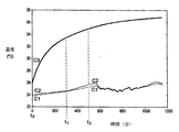
図3は、温度センサ21と22が感知した温度変化を、時間の関数とした図表を示している。曲線C1は、第1温度センサ21が感知した温度変化T1を表している。曲線C2は、第2温度センサ22が感知した温度変化T2を表している。曲線C3は、空間101に位置する電子、および/または電気コンポーネントから放出される熱の温度変化を表している。時間t0は、自動車が始動した時に対応し、従って、空間101に位置する全ての電子部品(コンポーネント)が始動した時である。時間t0と時間t1の間は約300分間であり、2つの温度センサ21,22は、空気ダクト4の中の空気A1の同じ温度を測定する。時間t1から、正面7は、日光にさらされ、空気ダクト4の中の空気A1の温度Ta1の増加が生じる。温度感知器1は、特に温度センサ21,22に太陽光線RSが与える直接的な影響を防ぐ手段を備え、温度センサ21,22は、熱的に結合し、太陽光線RSから放出された熱は、2つの温度センサ21,22により、同様にして考慮に入れられる。時間t1と時間t2の間は500分間であり、電子部品(コンポーネント)の温度は、第2温度センサ22が感知するT2が、第1端5aの近傍に位置する第1温度センサ21が感知する温度T1より高くなる程度に、充分高くなる。従って、温度T2の測定により、車室100の空気Aの温度Taを計算する時に、空間101の電子コンポーネントによる加熱を考慮に入れることが可能となる。これにより、車室100の空気Aの温度Taの真の値が、正確に決定される。温度感知器が、少なくとも2つの温度センサを備える場合、第2温度センサ22から第1温度センサ21を隔てる距離D2は、第1温度センサが空間101の電子コンポーネントにより放出された熱の影響を受けない程度に、大きくなければならない。
FIG. 3 shows a chart in which the temperature change detected by the
本発明は、図示してはいないが、上述の温度感知器1を備える、換気、暖房、および/または空調装置用の調節パネルにも関する。調節パネルは、主要電子カード10を備えている。
The present invention also relates to a control panel for ventilation, heating and / or air-conditioning equipment comprising the temperature sensor 1 described above, although not shown. The adjustment panel includes a main
様々な実施形態において使用される温度センサは、NTC(負温度係数)タイプのものである。 The temperature sensor used in various embodiments is of the NTC (negative temperature coefficient) type.
1 温度感知器
2 温度センサ
3 電線
3',3'' 接続ワイヤ
4 空気ダクト
5 第1部分
5a 第1端
6 第2部分
6a 第2端
6a1 第2端の面
6b 本体
7 正面
8 グリッド
9 孔
10 主要電子カード
10a 主要電子カードの面
12 第1コネクタ
13 第2コネクタ
21 第1温度センサ
22 第2温度センサ
100 車室
101 空間
1 Temperature sensor
2 Temperature sensor
3 Electric wire
3 ', 3''connecting wire
4 Air duct
5 Part 1
5a 1st end
6 Second part
6a 2nd end
6a1 Second end face
6b body
7 Front
8 grid
9 holes
10 Major electronic cards
10a Main electronic card face
12 First connector
13 Second connector
21 First temperature sensor
22 Second temperature sensor
100 car compartment
101 space
Claims (13)
Applications Claiming Priority (2)
| Application Number | Priority Date | Filing Date | Title |
|---|---|---|---|
| FR0701462A FR2913267B1 (en) | 2007-03-01 | 2007-03-01 | TEMPERATURE DETECTION DEVICE FOR A VEHICLE |
| PCT/EP2008/052487 WO2008107383A1 (en) | 2007-03-01 | 2008-02-29 | Temperature detection device for the passenger compartment of a vehicle |
Publications (1)
| Publication Number | Publication Date |
|---|---|
| JP2010520102A true JP2010520102A (en) | 2010-06-10 |
Family
ID=38664455
Family Applications (1)
| Application Number | Title | Priority Date | Filing Date |
|---|---|---|---|
| JP2009551222A Pending JP2010520102A (en) | 2007-03-01 | 2008-02-29 | Temperature sensor for passenger compartment |
Country Status (7)
| Country | Link |
|---|---|
| US (1) | US8382368B2 (en) |
| EP (1) | EP2126530A1 (en) |
| JP (1) | JP2010520102A (en) |
| BR (1) | BRPI0807396A2 (en) |
| FR (1) | FR2913267B1 (en) |
| MX (1) | MX2009009286A (en) |
| WO (1) | WO2008107383A1 (en) |
Families Citing this family (14)
| Publication number | Priority date | Publication date | Assignee | Title |
|---|---|---|---|---|
| GB2505664A (en) | 2012-09-06 | 2014-03-12 | Jaguar Land Rover Ltd | A vehicle cabin temperature control system |
| US10260968B2 (en) | 2013-03-15 | 2019-04-16 | Nano Composite Products, Inc. | Polymeric foam deformation gauge |
| AU2014229010B2 (en) | 2013-03-15 | 2018-05-10 | Nano Composite Products, Inc. | Composite material used as a strain gauge |
| FR3021613B1 (en) * | 2014-05-27 | 2017-11-24 | Renault Sas | METHOD OF ESTIMATING THE TIME TO REHABILITATE THE PERFORMANCE OF A TRACTION BATTERY OF A HYBRID VEHICLE |
| US9857246B2 (en) | 2014-09-17 | 2018-01-02 | Sensable Technologies, Llc | Sensing system including a sensing membrane |
| US10405779B2 (en) | 2015-01-07 | 2019-09-10 | Nano Composite Products, Inc. | Shoe-based analysis system |
| DE102015112186A1 (en) * | 2015-07-27 | 2017-02-02 | Dr. Ing. H.C. F. Porsche Aktiengesellschaft | Knee-joint with heat conduction device |
| US11408622B2 (en) * | 2015-08-27 | 2022-08-09 | Delta T, Llc | Control with enhanced sensing capabilities |
| WO2017192552A1 (en) * | 2016-05-02 | 2017-11-09 | Valeo Climate Control Corp. | Hvac module |
| WO2017192563A1 (en) * | 2016-05-02 | 2017-11-09 | Valeo Climate Control Corp. | Hvac module |
| DE102016110458B4 (en) * | 2016-06-07 | 2023-11-09 | Valeo Schalter Und Sensoren Gmbh | Control device for an automatic air conditioning system of a motor vehicle, automatic air conditioning system and motor vehicle |
| US10696380B2 (en) * | 2017-07-20 | 2020-06-30 | Hamilton Sunstrand Corporation | Aerodynamic control surface operating system for aircraft using variable transmission |
| US11897397B2 (en) * | 2019-06-05 | 2024-02-13 | WeRide Corp. | Mounting base for mounting sensors |
| CN115083704B (en) * | 2022-06-29 | 2025-10-14 | 安徽天康(集团)股份有限公司 | Special thermistor for EMU |
Citations (6)
| Publication number | Priority date | Publication date | Assignee | Title |
|---|---|---|---|---|
| JPS6279608U (en) * | 1985-11-08 | 1987-05-21 | ||
| JPH0450021A (en) * | 1990-06-19 | 1992-02-19 | Nissan Motor Co Ltd | Aspirator structure of automatic air conditioning device |
| JPH0513809U (en) * | 1990-10-29 | 1993-02-23 | カルソニツク株式会社 | Housing for mounting temperature sensor |
| JPH05294127A (en) * | 1992-04-24 | 1993-11-09 | Nippondenso Co Ltd | Internal air temperature detecting device of air conditioner for vehicle |
| JPH08188029A (en) * | 1995-01-12 | 1996-07-23 | Tgk Co Ltd | Aspirator for vehicular air conditioner |
| JPH09123732A (en) * | 1995-11-01 | 1997-05-13 | Zexel Corp | Air conditioner for automobile |
Family Cites Families (19)
| Publication number | Priority date | Publication date | Assignee | Title |
|---|---|---|---|---|
| DE2634015A1 (en) | 1976-07-29 | 1978-02-09 | Bosch Gmbh Robert | DEVICE FOR REGULATING THE TEMPERATURE OF THE INTERIOR OF A MOTOR VEHICLE |
| FR2554925B1 (en) * | 1983-11-10 | 1986-06-20 | Valeo | TEMPERATURE MEASURING DEVICE, PARTICULARLY FOR A TEMPERATURE REGULATION INSTALLATION IN THE INTERIOR OF A MOTOR VEHICLE |
| GB8918431D0 (en) | 1989-08-12 | 1989-09-20 | Lucas Ind Plc | Apparatus for aircraft flight |
| DE4142648C1 (en) | 1991-12-21 | 1993-04-29 | Mercedes-Benz Aktiengesellschaft, 7000 Stuttgart, De | Internal temp. detector for motor vehicle - has thermal device in stand pipe leading heated air to temp. sensor |
| DE19621092A1 (en) * | 1996-05-24 | 1997-11-27 | Saab Automobile | Vehicle interior temperature sensor |
| JPH09329503A (en) * | 1996-06-07 | 1997-12-22 | Ishikawajima Harima Heavy Ind Co Ltd | Temperature measuring device for heat transfer compensation |
| FR2796460B1 (en) * | 1999-07-16 | 2001-12-28 | Valeo Electronique | DEVICE FOR MEASURING THE TEMPERATURE INSIDE A MOTOR VEHICLE INTERIOR AND CONTROL PANEL COMPRISING SAME |
| SE513482C2 (en) | 1999-10-29 | 2000-09-18 | Scania Cv Ab | Device for calculating the temperature of a driver's compartment of a vehicle |
| DE10049979C5 (en) * | 2000-10-06 | 2005-12-22 | Behr-Hella Thermocontrol Gmbh | Device for determining the temperature in the interior of a vehicle |
| JP2004125427A (en) * | 2002-09-30 | 2004-04-22 | Ngk Spark Plug Co Ltd | Gas and temperature detector |
| DE10249583A1 (en) * | 2002-10-24 | 2004-05-13 | Preh-Werke Gmbh & Co. Kg | Arrangement for determining the interior temperature |
| DE10256001A1 (en) * | 2002-11-30 | 2004-06-17 | Adam Opel Ag | Motor vehicle with a heating and ventilation or air conditioning system |
| US6997605B2 (en) * | 2003-03-12 | 2006-02-14 | Behr-Hella Thermocontrol Gmbh | Device for detection of the temperature in the interior of a vehicle |
| US20060203886A1 (en) * | 2005-03-10 | 2006-09-14 | Aai Corporation | Simplified thermal isolator for temperature sensor |
| US7387437B2 (en) * | 2005-03-16 | 2008-06-17 | Ford Global Technologies, Llc | Method of determining ambient air temperature |
| FR2912503B1 (en) * | 2007-02-08 | 2009-05-15 | Valeo Systemes Thermiques | TEMPERATURE DETECTION DEVICE |
| FR2919524B1 (en) * | 2007-08-01 | 2009-10-30 | Valeo Systemes Thermiques | DEVICE FOR CONTROLLING THE TEMPERATURE OF THE AIR CONTAINED IN THE INTERIOR OF THE CABIN OF A VEHICLE |
| DE102008064011B3 (en) * | 2008-12-19 | 2010-07-01 | Behr-Hella Thermocontrol Gmbh | Device for detecting the interior temperature of a vehicle |
| JP5354211B2 (en) * | 2010-02-16 | 2013-11-27 | 株式会社デンソー | Vehicle temperature measurement device |
-
2007
- 2007-03-01 FR FR0701462A patent/FR2913267B1/en active Active
-
2008
- 2008-02-29 US US12/528,736 patent/US8382368B2/en active Active
- 2008-02-29 WO PCT/EP2008/052487 patent/WO2008107383A1/en not_active Ceased
- 2008-02-29 BR BRPI0807396-1A2A patent/BRPI0807396A2/en not_active Application Discontinuation
- 2008-02-29 EP EP08717268A patent/EP2126530A1/en not_active Withdrawn
- 2008-02-29 JP JP2009551222A patent/JP2010520102A/en active Pending
- 2008-02-29 MX MX2009009286A patent/MX2009009286A/en active IP Right Grant
Patent Citations (6)
| Publication number | Priority date | Publication date | Assignee | Title |
|---|---|---|---|---|
| JPS6279608U (en) * | 1985-11-08 | 1987-05-21 | ||
| JPH0450021A (en) * | 1990-06-19 | 1992-02-19 | Nissan Motor Co Ltd | Aspirator structure of automatic air conditioning device |
| JPH0513809U (en) * | 1990-10-29 | 1993-02-23 | カルソニツク株式会社 | Housing for mounting temperature sensor |
| JPH05294127A (en) * | 1992-04-24 | 1993-11-09 | Nippondenso Co Ltd | Internal air temperature detecting device of air conditioner for vehicle |
| JPH08188029A (en) * | 1995-01-12 | 1996-07-23 | Tgk Co Ltd | Aspirator for vehicular air conditioner |
| JPH09123732A (en) * | 1995-11-01 | 1997-05-13 | Zexel Corp | Air conditioner for automobile |
Also Published As
| Publication number | Publication date |
|---|---|
| US8382368B2 (en) | 2013-02-26 |
| MX2009009286A (en) | 2009-09-09 |
| WO2008107383A1 (en) | 2008-09-12 |
| US20100014556A1 (en) | 2010-01-21 |
| EP2126530A1 (en) | 2009-12-02 |
| BRPI0807396A2 (en) | 2014-06-03 |
| FR2913267B1 (en) | 2009-10-02 |
| FR2913267A1 (en) | 2008-09-05 |
Similar Documents
| Publication | Publication Date | Title |
|---|---|---|
| JP2010520102A (en) | Temperature sensor for passenger compartment | |
| US6422062B1 (en) | Integrated glass fog sensor unit | |
| EP1799475B1 (en) | An environmental control system for a vehicle | |
| JP4511969B2 (en) | Fixing device for sensor means | |
| US9022646B2 (en) | Sensor module for acquiring the temperature in the interior of a vehicle, and device for determining the temperature in the interior of a vehicle | |
| US9623801B2 (en) | Integrated inside mirror assembly of vehicle | |
| US20090097529A1 (en) | Sensor arrangement for the climate control of a motor vehicle | |
| KR101499746B1 (en) | Defog sensor unit | |
| JP2003522334A (en) | Sensor device | |
| KR101926471B1 (en) | Apparatus for Detecting Temperature and Humidity for Vehicle | |
| FR2846922A1 (en) | SUPPORT STRUCTURE FOR VEHICLE WITH INTEGRATED ELECTRONICS | |
| CN109476202B (en) | Operating device for an automatic climate control system of a motor vehicle, automatic climate control system and motor vehicle | |
| JP2012061879A (en) | Mounting structure of thermistor for temperature measurement for controlling automatic air conditioner | |
| EP1054313A1 (en) | Temperature sensor | |
| US7405669B2 (en) | Sensor arrangement | |
| JP2021153036A (en) | Heater unit and application thereof | |
| JP7661101B2 (en) | Windshield Device | |
| CN111795755A (en) | Sensor device, method for producing a sensor device, and vehicle | |
| KR200438165Y1 (en) | Glass fog detection module | |
| JP2023074465A (en) | Heater unit and its applied product | |
| JP2021111495A (en) | Heater unit and applied article thereof | |
| KR102740345B1 (en) | In-car sensor nodule for vehicles | |
| KR20210014852A (en) | Heating apparatus | |
| JPH068506Y2 (en) | Solar radiation detector | |
| CN215296494U (en) | Temperature sensor in car |
Legal Events
| Date | Code | Title | Description |
|---|---|---|---|
| A621 | Written request for application examination |
Free format text: JAPANESE INTERMEDIATE CODE: A621 Effective date: 20110126 |
|
| A977 | Report on retrieval |
Free format text: JAPANESE INTERMEDIATE CODE: A971007 Effective date: 20120606 |
|
| A131 | Notification of reasons for refusal |
Free format text: JAPANESE INTERMEDIATE CODE: A131 Effective date: 20120612 |
|
| A601 | Written request for extension of time |
Free format text: JAPANESE INTERMEDIATE CODE: A601 Effective date: 20120910 |
|
| A602 | Written permission of extension of time |
Free format text: JAPANESE INTERMEDIATE CODE: A602 Effective date: 20120918 |
|
| A601 | Written request for extension of time |
Free format text: JAPANESE INTERMEDIATE CODE: A601 Effective date: 20121011 |
|
| A602 | Written permission of extension of time |
Free format text: JAPANESE INTERMEDIATE CODE: A602 Effective date: 20121018 |
|
| A601 | Written request for extension of time |
Free format text: JAPANESE INTERMEDIATE CODE: A601 Effective date: 20121109 |
|
| A602 | Written permission of extension of time |
Free format text: JAPANESE INTERMEDIATE CODE: A602 Effective date: 20121116 |
|
| A521 | Request for written amendment filed |
Free format text: JAPANESE INTERMEDIATE CODE: A523 Effective date: 20121212 |
|
| A02 | Decision of refusal |
Free format text: JAPANESE INTERMEDIATE CODE: A02 Effective date: 20130618 |