JP2010518905A - Tissue-preserving implant - Google Patents
Tissue-preserving implant Download PDFInfo
- Publication number
- JP2010518905A JP2010518905A JP2009549648A JP2009549648A JP2010518905A JP 2010518905 A JP2010518905 A JP 2010518905A JP 2009549648 A JP2009549648 A JP 2009549648A JP 2009549648 A JP2009549648 A JP 2009549648A JP 2010518905 A JP2010518905 A JP 2010518905A
- Authority
- JP
- Japan
- Prior art keywords
- tissue
- stem component
- component
- preserving implant
- implant
- Prior art date
- Legal status (The legal status is an assumption and is not a legal conclusion. Google has not performed a legal analysis and makes no representation as to the accuracy of the status listed.)
- Pending
Links
Images


Classifications
-
- A—HUMAN NECESSITIES
- A61—MEDICAL OR VETERINARY SCIENCE; HYGIENE
- A61F—FILTERS IMPLANTABLE INTO BLOOD VESSELS; PROSTHESES; DEVICES PROVIDING PATENCY TO, OR PREVENTING COLLAPSING OF, TUBULAR STRUCTURES OF THE BODY, e.g. STENTS; ORTHOPAEDIC, NURSING OR CONTRACEPTIVE DEVICES; FOMENTATION; TREATMENT OR PROTECTION OF EYES OR EARS; BANDAGES, DRESSINGS OR ABSORBENT PADS; FIRST-AID KITS
- A61F2/00—Filters implantable into blood vessels; Prostheses, i.e. artificial substitutes or replacements for parts of the body; Appliances for connecting them with the body; Devices providing patency to, or preventing collapsing of, tubular structures of the body, e.g. stents
- A61F2/02—Prostheses implantable into the body
- A61F2/30—Joints
- A61F2/32—Joints for the hip
- A61F2/36—Femoral heads ; Femoral endoprostheses
- A61F2/3662—Femoral shafts
- A61F2/367—Proximal or metaphyseal parts of shafts
-
- A—HUMAN NECESSITIES
- A61—MEDICAL OR VETERINARY SCIENCE; HYGIENE
- A61F—FILTERS IMPLANTABLE INTO BLOOD VESSELS; PROSTHESES; DEVICES PROVIDING PATENCY TO, OR PREVENTING COLLAPSING OF, TUBULAR STRUCTURES OF THE BODY, e.g. STENTS; ORTHOPAEDIC, NURSING OR CONTRACEPTIVE DEVICES; FOMENTATION; TREATMENT OR PROTECTION OF EYES OR EARS; BANDAGES, DRESSINGS OR ABSORBENT PADS; FIRST-AID KITS
- A61F2/00—Filters implantable into blood vessels; Prostheses, i.e. artificial substitutes or replacements for parts of the body; Appliances for connecting them with the body; Devices providing patency to, or preventing collapsing of, tubular structures of the body, e.g. stents
- A61F2/02—Prostheses implantable into the body
- A61F2/30—Joints
- A61F2/32—Joints for the hip
- A61F2/36—Femoral heads ; Femoral endoprostheses
- A61F2/3601—Femoral heads ; Femoral endoprostheses for replacing only the epiphyseal or metaphyseal parts of the femur, e.g. endoprosthetic femoral heads or necks directly fixed to the natural femur by internal fixation devices
-
- A—HUMAN NECESSITIES
- A61—MEDICAL OR VETERINARY SCIENCE; HYGIENE
- A61F—FILTERS IMPLANTABLE INTO BLOOD VESSELS; PROSTHESES; DEVICES PROVIDING PATENCY TO, OR PREVENTING COLLAPSING OF, TUBULAR STRUCTURES OF THE BODY, e.g. STENTS; ORTHOPAEDIC, NURSING OR CONTRACEPTIVE DEVICES; FOMENTATION; TREATMENT OR PROTECTION OF EYES OR EARS; BANDAGES, DRESSINGS OR ABSORBENT PADS; FIRST-AID KITS
- A61F2/00—Filters implantable into blood vessels; Prostheses, i.e. artificial substitutes or replacements for parts of the body; Appliances for connecting them with the body; Devices providing patency to, or preventing collapsing of, tubular structures of the body, e.g. stents
- A61F2/02—Prostheses implantable into the body
- A61F2/30—Joints
- A61F2/32—Joints for the hip
- A61F2/36—Femoral heads ; Femoral endoprostheses
- A61F2/3609—Femoral heads or necks; Connections of endoprosthetic heads or necks to endoprosthetic femoral shafts
-
- A—HUMAN NECESSITIES
- A61—MEDICAL OR VETERINARY SCIENCE; HYGIENE
- A61F—FILTERS IMPLANTABLE INTO BLOOD VESSELS; PROSTHESES; DEVICES PROVIDING PATENCY TO, OR PREVENTING COLLAPSING OF, TUBULAR STRUCTURES OF THE BODY, e.g. STENTS; ORTHOPAEDIC, NURSING OR CONTRACEPTIVE DEVICES; FOMENTATION; TREATMENT OR PROTECTION OF EYES OR EARS; BANDAGES, DRESSINGS OR ABSORBENT PADS; FIRST-AID KITS
- A61F2/00—Filters implantable into blood vessels; Prostheses, i.e. artificial substitutes or replacements for parts of the body; Appliances for connecting them with the body; Devices providing patency to, or preventing collapsing of, tubular structures of the body, e.g. stents
- A61F2/02—Prostheses implantable into the body
- A61F2/30—Joints
- A61F2/32—Joints for the hip
- A61F2/36—Femoral heads ; Femoral endoprostheses
- A61F2/3662—Femoral shafts
-
- A—HUMAN NECESSITIES
- A61—MEDICAL OR VETERINARY SCIENCE; HYGIENE
- A61F—FILTERS IMPLANTABLE INTO BLOOD VESSELS; PROSTHESES; DEVICES PROVIDING PATENCY TO, OR PREVENTING COLLAPSING OF, TUBULAR STRUCTURES OF THE BODY, e.g. STENTS; ORTHOPAEDIC, NURSING OR CONTRACEPTIVE DEVICES; FOMENTATION; TREATMENT OR PROTECTION OF EYES OR EARS; BANDAGES, DRESSINGS OR ABSORBENT PADS; FIRST-AID KITS
- A61F2/00—Filters implantable into blood vessels; Prostheses, i.e. artificial substitutes or replacements for parts of the body; Appliances for connecting them with the body; Devices providing patency to, or preventing collapsing of, tubular structures of the body, e.g. stents
- A61F2/02—Prostheses implantable into the body
- A61F2/30—Joints
- A61F2002/30001—Additional features of subject-matter classified in A61F2/28, A61F2/30 and subgroups thereof
- A61F2002/30108—Shapes
- A61F2002/3011—Cross-sections or two-dimensional shapes
- A61F2002/30112—Rounded shapes, e.g. with rounded corners
-
- A—HUMAN NECESSITIES
- A61—MEDICAL OR VETERINARY SCIENCE; HYGIENE
- A61F—FILTERS IMPLANTABLE INTO BLOOD VESSELS; PROSTHESES; DEVICES PROVIDING PATENCY TO, OR PREVENTING COLLAPSING OF, TUBULAR STRUCTURES OF THE BODY, e.g. STENTS; ORTHOPAEDIC, NURSING OR CONTRACEPTIVE DEVICES; FOMENTATION; TREATMENT OR PROTECTION OF EYES OR EARS; BANDAGES, DRESSINGS OR ABSORBENT PADS; FIRST-AID KITS
- A61F2/00—Filters implantable into blood vessels; Prostheses, i.e. artificial substitutes or replacements for parts of the body; Appliances for connecting them with the body; Devices providing patency to, or preventing collapsing of, tubular structures of the body, e.g. stents
- A61F2/02—Prostheses implantable into the body
- A61F2/30—Joints
- A61F2002/30001—Additional features of subject-matter classified in A61F2/28, A61F2/30 and subgroups thereof
- A61F2002/30108—Shapes
- A61F2002/3011—Cross-sections or two-dimensional shapes
- A61F2002/30138—Convex polygonal shapes
- A61F2002/30153—Convex polygonal shapes rectangular
-
- A—HUMAN NECESSITIES
- A61—MEDICAL OR VETERINARY SCIENCE; HYGIENE
- A61F—FILTERS IMPLANTABLE INTO BLOOD VESSELS; PROSTHESES; DEVICES PROVIDING PATENCY TO, OR PREVENTING COLLAPSING OF, TUBULAR STRUCTURES OF THE BODY, e.g. STENTS; ORTHOPAEDIC, NURSING OR CONTRACEPTIVE DEVICES; FOMENTATION; TREATMENT OR PROTECTION OF EYES OR EARS; BANDAGES, DRESSINGS OR ABSORBENT PADS; FIRST-AID KITS
- A61F2/00—Filters implantable into blood vessels; Prostheses, i.e. artificial substitutes or replacements for parts of the body; Appliances for connecting them with the body; Devices providing patency to, or preventing collapsing of, tubular structures of the body, e.g. stents
- A61F2/02—Prostheses implantable into the body
- A61F2/30—Joints
- A61F2002/30001—Additional features of subject-matter classified in A61F2/28, A61F2/30 and subgroups thereof
- A61F2002/30108—Shapes
- A61F2002/3011—Cross-sections or two-dimensional shapes
- A61F2002/30159—Concave polygonal shapes
- A61F2002/30172—T-shaped
-
- A—HUMAN NECESSITIES
- A61—MEDICAL OR VETERINARY SCIENCE; HYGIENE
- A61F—FILTERS IMPLANTABLE INTO BLOOD VESSELS; PROSTHESES; DEVICES PROVIDING PATENCY TO, OR PREVENTING COLLAPSING OF, TUBULAR STRUCTURES OF THE BODY, e.g. STENTS; ORTHOPAEDIC, NURSING OR CONTRACEPTIVE DEVICES; FOMENTATION; TREATMENT OR PROTECTION OF EYES OR EARS; BANDAGES, DRESSINGS OR ABSORBENT PADS; FIRST-AID KITS
- A61F2/00—Filters implantable into blood vessels; Prostheses, i.e. artificial substitutes or replacements for parts of the body; Appliances for connecting them with the body; Devices providing patency to, or preventing collapsing of, tubular structures of the body, e.g. stents
- A61F2/02—Prostheses implantable into the body
- A61F2/30—Joints
- A61F2002/30001—Additional features of subject-matter classified in A61F2/28, A61F2/30 and subgroups thereof
- A61F2002/30108—Shapes
- A61F2002/30199—Three-dimensional shapes
- A61F2002/30205—Three-dimensional shapes conical
-
- A—HUMAN NECESSITIES
- A61—MEDICAL OR VETERINARY SCIENCE; HYGIENE
- A61F—FILTERS IMPLANTABLE INTO BLOOD VESSELS; PROSTHESES; DEVICES PROVIDING PATENCY TO, OR PREVENTING COLLAPSING OF, TUBULAR STRUCTURES OF THE BODY, e.g. STENTS; ORTHOPAEDIC, NURSING OR CONTRACEPTIVE DEVICES; FOMENTATION; TREATMENT OR PROTECTION OF EYES OR EARS; BANDAGES, DRESSINGS OR ABSORBENT PADS; FIRST-AID KITS
- A61F2/00—Filters implantable into blood vessels; Prostheses, i.e. artificial substitutes or replacements for parts of the body; Appliances for connecting them with the body; Devices providing patency to, or preventing collapsing of, tubular structures of the body, e.g. stents
- A61F2/02—Prostheses implantable into the body
- A61F2/30—Joints
- A61F2002/30001—Additional features of subject-matter classified in A61F2/28, A61F2/30 and subgroups thereof
- A61F2002/30316—The prosthesis having different structural features at different locations within the same prosthesis; Connections between prosthetic parts; Special structural features of bone or joint prostheses not otherwise provided for
- A61F2002/30329—Connections or couplings between prosthetic parts, e.g. between modular parts; Connecting elements
- A61F2002/30331—Connections or couplings between prosthetic parts, e.g. between modular parts; Connecting elements made by longitudinally pushing a protrusion into a complementarily-shaped recess, e.g. held by friction fit
- A61F2002/30332—Conically- or frustoconically-shaped protrusion and recess
- A61F2002/30334—Cone of elliptical or oval basis
-
- A—HUMAN NECESSITIES
- A61—MEDICAL OR VETERINARY SCIENCE; HYGIENE
- A61F—FILTERS IMPLANTABLE INTO BLOOD VESSELS; PROSTHESES; DEVICES PROVIDING PATENCY TO, OR PREVENTING COLLAPSING OF, TUBULAR STRUCTURES OF THE BODY, e.g. STENTS; ORTHOPAEDIC, NURSING OR CONTRACEPTIVE DEVICES; FOMENTATION; TREATMENT OR PROTECTION OF EYES OR EARS; BANDAGES, DRESSINGS OR ABSORBENT PADS; FIRST-AID KITS
- A61F2/00—Filters implantable into blood vessels; Prostheses, i.e. artificial substitutes or replacements for parts of the body; Appliances for connecting them with the body; Devices providing patency to, or preventing collapsing of, tubular structures of the body, e.g. stents
- A61F2/02—Prostheses implantable into the body
- A61F2/30—Joints
- A61F2002/30001—Additional features of subject-matter classified in A61F2/28, A61F2/30 and subgroups thereof
- A61F2002/30316—The prosthesis having different structural features at different locations within the same prosthesis; Connections between prosthetic parts; Special structural features of bone or joint prostheses not otherwise provided for
- A61F2002/30329—Connections or couplings between prosthetic parts, e.g. between modular parts; Connecting elements
- A61F2002/30331—Connections or couplings between prosthetic parts, e.g. between modular parts; Connecting elements made by longitudinally pushing a protrusion into a complementarily-shaped recess, e.g. held by friction fit
- A61F2002/30332—Conically- or frustoconically-shaped protrusion and recess
- A61F2002/30339—Double cones, i.e. connecting element having two conical connections, one at each of its opposite ends
-
- A—HUMAN NECESSITIES
- A61—MEDICAL OR VETERINARY SCIENCE; HYGIENE
- A61F—FILTERS IMPLANTABLE INTO BLOOD VESSELS; PROSTHESES; DEVICES PROVIDING PATENCY TO, OR PREVENTING COLLAPSING OF, TUBULAR STRUCTURES OF THE BODY, e.g. STENTS; ORTHOPAEDIC, NURSING OR CONTRACEPTIVE DEVICES; FOMENTATION; TREATMENT OR PROTECTION OF EYES OR EARS; BANDAGES, DRESSINGS OR ABSORBENT PADS; FIRST-AID KITS
- A61F2/00—Filters implantable into blood vessels; Prostheses, i.e. artificial substitutes or replacements for parts of the body; Appliances for connecting them with the body; Devices providing patency to, or preventing collapsing of, tubular structures of the body, e.g. stents
- A61F2/02—Prostheses implantable into the body
- A61F2/30—Joints
- A61F2002/30001—Additional features of subject-matter classified in A61F2/28, A61F2/30 and subgroups thereof
- A61F2002/30316—The prosthesis having different structural features at different locations within the same prosthesis; Connections between prosthetic parts; Special structural features of bone or joint prostheses not otherwise provided for
- A61F2002/30535—Special structural features of bone or joint prostheses not otherwise provided for
- A61F2002/30537—Special structural features of bone or joint prostheses not otherwise provided for adjustable
- A61F2002/30538—Special structural features of bone or joint prostheses not otherwise provided for adjustable for adjusting angular orientation
- A61F2002/3054—Special structural features of bone or joint prostheses not otherwise provided for adjustable for adjusting angular orientation about a connection axis or implantation axis for selecting any one of a plurality of radial orientations between two modular parts, e.g. Morse taper connections, at discrete positions, angular positions or continuous positions
-
- A—HUMAN NECESSITIES
- A61—MEDICAL OR VETERINARY SCIENCE; HYGIENE
- A61F—FILTERS IMPLANTABLE INTO BLOOD VESSELS; PROSTHESES; DEVICES PROVIDING PATENCY TO, OR PREVENTING COLLAPSING OF, TUBULAR STRUCTURES OF THE BODY, e.g. STENTS; ORTHOPAEDIC, NURSING OR CONTRACEPTIVE DEVICES; FOMENTATION; TREATMENT OR PROTECTION OF EYES OR EARS; BANDAGES, DRESSINGS OR ABSORBENT PADS; FIRST-AID KITS
- A61F2/00—Filters implantable into blood vessels; Prostheses, i.e. artificial substitutes or replacements for parts of the body; Appliances for connecting them with the body; Devices providing patency to, or preventing collapsing of, tubular structures of the body, e.g. stents
- A61F2/02—Prostheses implantable into the body
- A61F2/30—Joints
- A61F2002/30001—Additional features of subject-matter classified in A61F2/28, A61F2/30 and subgroups thereof
- A61F2002/30316—The prosthesis having different structural features at different locations within the same prosthesis; Connections between prosthetic parts; Special structural features of bone or joint prostheses not otherwise provided for
- A61F2002/30535—Special structural features of bone or joint prostheses not otherwise provided for
- A61F2002/30593—Special structural features of bone or joint prostheses not otherwise provided for hollow
-
- A—HUMAN NECESSITIES
- A61—MEDICAL OR VETERINARY SCIENCE; HYGIENE
- A61F—FILTERS IMPLANTABLE INTO BLOOD VESSELS; PROSTHESES; DEVICES PROVIDING PATENCY TO, OR PREVENTING COLLAPSING OF, TUBULAR STRUCTURES OF THE BODY, e.g. STENTS; ORTHOPAEDIC, NURSING OR CONTRACEPTIVE DEVICES; FOMENTATION; TREATMENT OR PROTECTION OF EYES OR EARS; BANDAGES, DRESSINGS OR ABSORBENT PADS; FIRST-AID KITS
- A61F2/00—Filters implantable into blood vessels; Prostheses, i.e. artificial substitutes or replacements for parts of the body; Appliances for connecting them with the body; Devices providing patency to, or preventing collapsing of, tubular structures of the body, e.g. stents
- A61F2/02—Prostheses implantable into the body
- A61F2/30—Joints
- A61F2002/30001—Additional features of subject-matter classified in A61F2/28, A61F2/30 and subgroups thereof
- A61F2002/30316—The prosthesis having different structural features at different locations within the same prosthesis; Connections between prosthetic parts; Special structural features of bone or joint prostheses not otherwise provided for
- A61F2002/30535—Special structural features of bone or joint prostheses not otherwise provided for
- A61F2002/30594—Special structural features of bone or joint prostheses not otherwise provided for slotted, e.g. radial or meridian slot ending in a polar aperture, non-polar slots, horizontal or arcuate slots
-
- A—HUMAN NECESSITIES
- A61—MEDICAL OR VETERINARY SCIENCE; HYGIENE
- A61F—FILTERS IMPLANTABLE INTO BLOOD VESSELS; PROSTHESES; DEVICES PROVIDING PATENCY TO, OR PREVENTING COLLAPSING OF, TUBULAR STRUCTURES OF THE BODY, e.g. STENTS; ORTHOPAEDIC, NURSING OR CONTRACEPTIVE DEVICES; FOMENTATION; TREATMENT OR PROTECTION OF EYES OR EARS; BANDAGES, DRESSINGS OR ABSORBENT PADS; FIRST-AID KITS
- A61F2/00—Filters implantable into blood vessels; Prostheses, i.e. artificial substitutes or replacements for parts of the body; Appliances for connecting them with the body; Devices providing patency to, or preventing collapsing of, tubular structures of the body, e.g. stents
- A61F2/02—Prostheses implantable into the body
- A61F2/30—Joints
- A61F2002/30001—Additional features of subject-matter classified in A61F2/28, A61F2/30 and subgroups thereof
- A61F2002/30316—The prosthesis having different structural features at different locations within the same prosthesis; Connections between prosthetic parts; Special structural features of bone or joint prostheses not otherwise provided for
- A61F2002/30535—Special structural features of bone or joint prostheses not otherwise provided for
- A61F2002/30604—Special structural features of bone or joint prostheses not otherwise provided for modular
- A61F2002/30616—Sets comprising a plurality of prosthetic parts of different sizes or orientations
-
- A—HUMAN NECESSITIES
- A61—MEDICAL OR VETERINARY SCIENCE; HYGIENE
- A61F—FILTERS IMPLANTABLE INTO BLOOD VESSELS; PROSTHESES; DEVICES PROVIDING PATENCY TO, OR PREVENTING COLLAPSING OF, TUBULAR STRUCTURES OF THE BODY, e.g. STENTS; ORTHOPAEDIC, NURSING OR CONTRACEPTIVE DEVICES; FOMENTATION; TREATMENT OR PROTECTION OF EYES OR EARS; BANDAGES, DRESSINGS OR ABSORBENT PADS; FIRST-AID KITS
- A61F2/00—Filters implantable into blood vessels; Prostheses, i.e. artificial substitutes or replacements for parts of the body; Appliances for connecting them with the body; Devices providing patency to, or preventing collapsing of, tubular structures of the body, e.g. stents
- A61F2/02—Prostheses implantable into the body
- A61F2/30—Joints
- A61F2/30767—Special external or bone-contacting surface, e.g. coating for improving bone ingrowth
- A61F2/30771—Special external or bone-contacting surface, e.g. coating for improving bone ingrowth applied in original prostheses, e.g. holes or grooves
- A61F2002/30878—Special external or bone-contacting surface, e.g. coating for improving bone ingrowth applied in original prostheses, e.g. holes or grooves with non-sharp protrusions, for instance contacting the bone for anchoring, e.g. keels, pegs, pins, posts, shanks, stems, struts
- A61F2002/30879—Ribs
-
- A—HUMAN NECESSITIES
- A61—MEDICAL OR VETERINARY SCIENCE; HYGIENE
- A61F—FILTERS IMPLANTABLE INTO BLOOD VESSELS; PROSTHESES; DEVICES PROVIDING PATENCY TO, OR PREVENTING COLLAPSING OF, TUBULAR STRUCTURES OF THE BODY, e.g. STENTS; ORTHOPAEDIC, NURSING OR CONTRACEPTIVE DEVICES; FOMENTATION; TREATMENT OR PROTECTION OF EYES OR EARS; BANDAGES, DRESSINGS OR ABSORBENT PADS; FIRST-AID KITS
- A61F2/00—Filters implantable into blood vessels; Prostheses, i.e. artificial substitutes or replacements for parts of the body; Appliances for connecting them with the body; Devices providing patency to, or preventing collapsing of, tubular structures of the body, e.g. stents
- A61F2/02—Prostheses implantable into the body
- A61F2/30—Joints
- A61F2/30767—Special external or bone-contacting surface, e.g. coating for improving bone ingrowth
- A61F2/30771—Special external or bone-contacting surface, e.g. coating for improving bone ingrowth applied in original prostheses, e.g. holes or grooves
- A61F2002/30878—Special external or bone-contacting surface, e.g. coating for improving bone ingrowth applied in original prostheses, e.g. holes or grooves with non-sharp protrusions, for instance contacting the bone for anchoring, e.g. keels, pegs, pins, posts, shanks, stems, struts
- A61F2002/30884—Fins or wings, e.g. longitudinal wings for preventing rotation within the bone cavity
-
- A—HUMAN NECESSITIES
- A61—MEDICAL OR VETERINARY SCIENCE; HYGIENE
- A61F—FILTERS IMPLANTABLE INTO BLOOD VESSELS; PROSTHESES; DEVICES PROVIDING PATENCY TO, OR PREVENTING COLLAPSING OF, TUBULAR STRUCTURES OF THE BODY, e.g. STENTS; ORTHOPAEDIC, NURSING OR CONTRACEPTIVE DEVICES; FOMENTATION; TREATMENT OR PROTECTION OF EYES OR EARS; BANDAGES, DRESSINGS OR ABSORBENT PADS; FIRST-AID KITS
- A61F2/00—Filters implantable into blood vessels; Prostheses, i.e. artificial substitutes or replacements for parts of the body; Appliances for connecting them with the body; Devices providing patency to, or preventing collapsing of, tubular structures of the body, e.g. stents
- A61F2/02—Prostheses implantable into the body
- A61F2/30—Joints
- A61F2/32—Joints for the hip
- A61F2/36—Femoral heads ; Femoral endoprostheses
- A61F2/3609—Femoral heads or necks; Connections of endoprosthetic heads or necks to endoprosthetic femoral shafts
- A61F2002/365—Connections of heads to necks
-
- A—HUMAN NECESSITIES
- A61—MEDICAL OR VETERINARY SCIENCE; HYGIENE
- A61F—FILTERS IMPLANTABLE INTO BLOOD VESSELS; PROSTHESES; DEVICES PROVIDING PATENCY TO, OR PREVENTING COLLAPSING OF, TUBULAR STRUCTURES OF THE BODY, e.g. STENTS; ORTHOPAEDIC, NURSING OR CONTRACEPTIVE DEVICES; FOMENTATION; TREATMENT OR PROTECTION OF EYES OR EARS; BANDAGES, DRESSINGS OR ABSORBENT PADS; FIRST-AID KITS
- A61F2/00—Filters implantable into blood vessels; Prostheses, i.e. artificial substitutes or replacements for parts of the body; Appliances for connecting them with the body; Devices providing patency to, or preventing collapsing of, tubular structures of the body, e.g. stents
- A61F2/02—Prostheses implantable into the body
- A61F2/30—Joints
- A61F2/32—Joints for the hip
- A61F2/36—Femoral heads ; Femoral endoprostheses
- A61F2/3609—Femoral heads or necks; Connections of endoprosthetic heads or necks to endoprosthetic femoral shafts
- A61F2002/3652—Connections of necks to shafts
-
- A—HUMAN NECESSITIES
- A61—MEDICAL OR VETERINARY SCIENCE; HYGIENE
- A61F—FILTERS IMPLANTABLE INTO BLOOD VESSELS; PROSTHESES; DEVICES PROVIDING PATENCY TO, OR PREVENTING COLLAPSING OF, TUBULAR STRUCTURES OF THE BODY, e.g. STENTS; ORTHOPAEDIC, NURSING OR CONTRACEPTIVE DEVICES; FOMENTATION; TREATMENT OR PROTECTION OF EYES OR EARS; BANDAGES, DRESSINGS OR ABSORBENT PADS; FIRST-AID KITS
- A61F2/00—Filters implantable into blood vessels; Prostheses, i.e. artificial substitutes or replacements for parts of the body; Appliances for connecting them with the body; Devices providing patency to, or preventing collapsing of, tubular structures of the body, e.g. stents
- A61F2/02—Prostheses implantable into the body
- A61F2/30—Joints
- A61F2/32—Joints for the hip
- A61F2/36—Femoral heads ; Femoral endoprostheses
- A61F2/3662—Femoral shafts
- A61F2002/3678—Geometrical features
- A61F2002/3686—Geometrical features bent
-
- A—HUMAN NECESSITIES
- A61—MEDICAL OR VETERINARY SCIENCE; HYGIENE
- A61F—FILTERS IMPLANTABLE INTO BLOOD VESSELS; PROSTHESES; DEVICES PROVIDING PATENCY TO, OR PREVENTING COLLAPSING OF, TUBULAR STRUCTURES OF THE BODY, e.g. STENTS; ORTHOPAEDIC, NURSING OR CONTRACEPTIVE DEVICES; FOMENTATION; TREATMENT OR PROTECTION OF EYES OR EARS; BANDAGES, DRESSINGS OR ABSORBENT PADS; FIRST-AID KITS
- A61F2220/00—Fixations or connections for prostheses classified in groups A61F2/00 - A61F2/26 or A61F2/82 or A61F9/00 or A61F11/00 or subgroups thereof
- A61F2220/0025—Connections or couplings between prosthetic parts, e.g. between modular parts; Connecting elements
- A61F2220/0033—Connections or couplings between prosthetic parts, e.g. between modular parts; Connecting elements made by longitudinally pushing a protrusion into a complementary-shaped recess, e.g. held by friction fit
-
- A—HUMAN NECESSITIES
- A61—MEDICAL OR VETERINARY SCIENCE; HYGIENE
- A61F—FILTERS IMPLANTABLE INTO BLOOD VESSELS; PROSTHESES; DEVICES PROVIDING PATENCY TO, OR PREVENTING COLLAPSING OF, TUBULAR STRUCTURES OF THE BODY, e.g. STENTS; ORTHOPAEDIC, NURSING OR CONTRACEPTIVE DEVICES; FOMENTATION; TREATMENT OR PROTECTION OF EYES OR EARS; BANDAGES, DRESSINGS OR ABSORBENT PADS; FIRST-AID KITS
- A61F2230/00—Geometry of prostheses classified in groups A61F2/00 - A61F2/26 or A61F2/82 or A61F9/00 or A61F11/00 or subgroups thereof
- A61F2230/0002—Two-dimensional shapes, e.g. cross-sections
- A61F2230/0004—Rounded shapes, e.g. with rounded corners
-
- A—HUMAN NECESSITIES
- A61—MEDICAL OR VETERINARY SCIENCE; HYGIENE
- A61F—FILTERS IMPLANTABLE INTO BLOOD VESSELS; PROSTHESES; DEVICES PROVIDING PATENCY TO, OR PREVENTING COLLAPSING OF, TUBULAR STRUCTURES OF THE BODY, e.g. STENTS; ORTHOPAEDIC, NURSING OR CONTRACEPTIVE DEVICES; FOMENTATION; TREATMENT OR PROTECTION OF EYES OR EARS; BANDAGES, DRESSINGS OR ABSORBENT PADS; FIRST-AID KITS
- A61F2230/00—Geometry of prostheses classified in groups A61F2/00 - A61F2/26 or A61F2/82 or A61F9/00 or A61F11/00 or subgroups thereof
- A61F2230/0002—Two-dimensional shapes, e.g. cross-sections
- A61F2230/0017—Angular shapes
- A61F2230/0019—Angular shapes rectangular
-
- A—HUMAN NECESSITIES
- A61—MEDICAL OR VETERINARY SCIENCE; HYGIENE
- A61F—FILTERS IMPLANTABLE INTO BLOOD VESSELS; PROSTHESES; DEVICES PROVIDING PATENCY TO, OR PREVENTING COLLAPSING OF, TUBULAR STRUCTURES OF THE BODY, e.g. STENTS; ORTHOPAEDIC, NURSING OR CONTRACEPTIVE DEVICES; FOMENTATION; TREATMENT OR PROTECTION OF EYES OR EARS; BANDAGES, DRESSINGS OR ABSORBENT PADS; FIRST-AID KITS
- A61F2230/00—Geometry of prostheses classified in groups A61F2/00 - A61F2/26 or A61F2/82 or A61F9/00 or A61F11/00 or subgroups thereof
- A61F2230/0002—Two-dimensional shapes, e.g. cross-sections
- A61F2230/0028—Shapes in the form of latin or greek characters
- A61F2230/0052—T-shaped
-
- A—HUMAN NECESSITIES
- A61—MEDICAL OR VETERINARY SCIENCE; HYGIENE
- A61F—FILTERS IMPLANTABLE INTO BLOOD VESSELS; PROSTHESES; DEVICES PROVIDING PATENCY TO, OR PREVENTING COLLAPSING OF, TUBULAR STRUCTURES OF THE BODY, e.g. STENTS; ORTHOPAEDIC, NURSING OR CONTRACEPTIVE DEVICES; FOMENTATION; TREATMENT OR PROTECTION OF EYES OR EARS; BANDAGES, DRESSINGS OR ABSORBENT PADS; FIRST-AID KITS
- A61F2230/00—Geometry of prostheses classified in groups A61F2/00 - A61F2/26 or A61F2/82 or A61F9/00 or A61F11/00 or subgroups thereof
- A61F2230/0063—Three-dimensional shapes
- A61F2230/0067—Three-dimensional shapes conical
-
- A—HUMAN NECESSITIES
- A61—MEDICAL OR VETERINARY SCIENCE; HYGIENE
- A61F—FILTERS IMPLANTABLE INTO BLOOD VESSELS; PROSTHESES; DEVICES PROVIDING PATENCY TO, OR PREVENTING COLLAPSING OF, TUBULAR STRUCTURES OF THE BODY, e.g. STENTS; ORTHOPAEDIC, NURSING OR CONTRACEPTIVE DEVICES; FOMENTATION; TREATMENT OR PROTECTION OF EYES OR EARS; BANDAGES, DRESSINGS OR ABSORBENT PADS; FIRST-AID KITS
- A61F2250/00—Special features of prostheses classified in groups A61F2/00 - A61F2/26 or A61F2/82 or A61F9/00 or A61F11/00 or subgroups thereof
- A61F2250/0004—Special features of prostheses classified in groups A61F2/00 - A61F2/26 or A61F2/82 or A61F9/00 or A61F11/00 or subgroups thereof adjustable
- A61F2250/0006—Special features of prostheses classified in groups A61F2/00 - A61F2/26 or A61F2/82 or A61F9/00 or A61F11/00 or subgroups thereof adjustable for adjusting angular orientation
-
- A—HUMAN NECESSITIES
- A61—MEDICAL OR VETERINARY SCIENCE; HYGIENE
- A61F—FILTERS IMPLANTABLE INTO BLOOD VESSELS; PROSTHESES; DEVICES PROVIDING PATENCY TO, OR PREVENTING COLLAPSING OF, TUBULAR STRUCTURES OF THE BODY, e.g. STENTS; ORTHOPAEDIC, NURSING OR CONTRACEPTIVE DEVICES; FOMENTATION; TREATMENT OR PROTECTION OF EYES OR EARS; BANDAGES, DRESSINGS OR ABSORBENT PADS; FIRST-AID KITS
- A61F2250/00—Special features of prostheses classified in groups A61F2/00 - A61F2/26 or A61F2/82 or A61F9/00 or A61F11/00 or subgroups thereof
- A61F2250/0058—Additional features; Implant or prostheses properties not otherwise provided for
- A61F2250/006—Additional features; Implant or prostheses properties not otherwise provided for modular
Landscapes
- Health & Medical Sciences (AREA)
- Orthopedic Medicine & Surgery (AREA)
- Cardiology (AREA)
- Oral & Maxillofacial Surgery (AREA)
- Transplantation (AREA)
- Engineering & Computer Science (AREA)
- Biomedical Technology (AREA)
- Heart & Thoracic Surgery (AREA)
- Vascular Medicine (AREA)
- Life Sciences & Earth Sciences (AREA)
- Animal Behavior & Ethology (AREA)
- General Health & Medical Sciences (AREA)
- Public Health (AREA)
- Veterinary Medicine (AREA)
- Prostheses (AREA)
Abstract
股関節インプラントの大腿骨構成要素が開示される。大腿骨構成要素は、具体的には頸部温存式切除術(即ち、大腿骨頸部の除去を回避する任意の方法または装置)で使用されていてもよく、近位大腿骨の内側距部分に内部で接触する末端フレア部を有する短縮された幹(従来の幹に対して)と、その内側面上に顕著な湾曲と、を含んでいてもよい。大腿骨構成要素の他の特徴は、幹の前面及び後面上の平坦側面部分と、ねじり力に抵抗する際に助けとなる側鰭または翼背面もしくはT背面と、を含む。大腿骨構成要素はまた、大腿管内での適切な装着及び配置のための矢状刻み溝を含んでいてもよい。大腿骨構成要素はまた、幹構成要素に対してモジュール式の頸部構成要素を含んでいてもよい。また、頭部構成要素は、頸部構成要素に対して一体鋳造かモジュール式かを問わず、大腿骨構成要素の一部として利用されていてもよい。 A femoral component of a hip implant is disclosed. The femoral component may be used specifically in a neck-sparing resection (ie, any method or device that avoids removal of the femoral neck) and the medial limb portion of the proximal femur May include a shortened stem (with respect to a conventional stem) having a terminal flared portion that contacts the inside and a pronounced curvature on its inside surface. Other features of the femoral component include flat side portions on the anterior and posterior surfaces of the trunk and a scoliosis or wing back or T back that helps in resisting torsional forces. The femoral component may also include a sagittal kerf for proper placement and placement within the femoral canal. The femoral component may also include a cervical component that is modular with respect to the trunk component. Further, the head component may be used as a part of the femoral component regardless of whether it is integrally cast or modular with respect to the neck component.
Description
本開示は、一般的に、第一次完全股関節形成術(Primary Total Hip Arthroplasty)、即ち人工股関節全置換術、に使用するための整形外科インプラントに関する。具体的には、本開示は、全股関節インプラントの大腿骨構成要素に関し、特に、必ずしも完全にではないが、大腿骨の髄管に設置されるかまたは配置され得る大腿骨頸部温存幹(femoral neck sparing stem)に関する。 The present disclosure relates generally to orthopedic implants for use in primary total hip arthroplasty, ie total hip arthroplasty. In particular, the present disclosure relates to femoral components of total hip implants, and in particular, but not necessarily completely, femoral neck preserved trunks that can be placed or placed in the medullary canal of the femur. neck sparring stem).
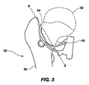
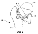
股関節インプラントは、整形外科業界でよく知られている。ここで、図1〜図4を参照すると、完全股関節形成術(「THA」)では、大腿骨頭12、頸部14及び骨幹16を含む自然大腿骨10は、股関節インプラントの大腿骨構成要素を受容するように外科的に準備される。人工大腿骨構成要素を受容する大腿骨10の準備では、整形外科医が、自然大腿骨10から大腿骨頭12を除去または切除することが多い。大腿骨頭12の除去には、一般に、実施され得る2種類の切除があり、それらは従来式と頸部温存式とである。2種類の切除の違いは、図2、図2A、図3及び図4に最もよく示されており、図2及び図3の3−3線で従来式切除が示されている。反対に、頸部温存式切除(neck sparing resection)は、図2及び図4に示されており、実際の切断は、図2の1−1線の真下で成され得る。
Hip implants are well known in the orthopedic industry. 1-4, in total hip arthroplasty ("THA"), the
当然のことながら、THAに使用される股関節インプラントの種類は、実施される大腿骨頭12の切除の種類に大きく左右される。大腿骨10の内側近位部分18、即ち大腿骨10の内側距部分、の適切な荷重が生じるのであれば(図2及び図2Aの符号18を参照)、より多くの骨がそれにより温存され、感染症、インプラント不全等に因り後に再手術が必要になった場合に将来の使用に備えて保存されるため、頸部温存式切除が好まれ得る。将来的な再手術が必要な場合で、最初の切除が頸部温存式であった場合には、その時に従来式切除が使用され得る。頸部温存手法は、それにより、より長い期間、患者の動き易さを拡張する可能性があり、20年以上長くなることもある。
Of course, the type of hip implant used for THA is highly dependent on the type of
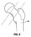
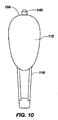
図5は、従来式切除または切断が行われる場合に使用され得る、股関節インプラントの大腿骨構成要素を示す。図6は、頸部温存式切除を用いて温存され得る大腿骨頸部14の骨量と、頸部温存式切除または切断が行われる場合に使用され得る股関節インプラントの既知の大腿骨構成要素とを示す。
FIG. 5 shows a femoral component of a hip implant that can be used when a conventional resection or cutting is performed. FIG. 6 shows the bone mass of the
自然骨には、より硬いより高密度の皮質骨がある位置の外側から荷重が掛けられることを理解されたい。反対に、整形外科インプラントは、大腿管内に配置される硬い通常は金属製の幹に因り、自然骨の荷重の性質を変更する。要するに、荷重が幹をたどり、そこから外側に向かうので、インプラントは、外側から内側へから内側から外側へと、骨の自然な荷重を変更する。さらに、骨に不適切に荷重が掛けられると、骨は再吸収し、それにより、無菌性の弛み及びインプラントの不全をもたらす。したがって、骨に適切に荷重を掛け、インプラントの効能を増大させることが、最も重要である。 It should be understood that natural bone is loaded from outside the location where there is a harder, higher density cortical bone. In contrast, orthopedic implants alter the nature of natural bone loading due to the stiff, usually metallic trunk placed in the femoral canal. In essence, as the load follows the trunk and then outwards, the implant changes the natural load of the bone from the outside to the inside to the inside to the outside. In addition, if the bone is improperly loaded, it will resorb, resulting in aseptic loosening and implant failure. Therefore, it is most important to properly load the bone and increase the effectiveness of the implant.
大腿骨10の内側近位部分18に荷重を掛ける必要性、またはその欠如のため、骨における大腿骨頸部14の部分の除去または維持に因り、図5及び図6に示された大腿骨構成要素の全体の寸法及び幾何学的形状が、大きく異なることは言うまでもない。
Due to the need for, or lack of, loading of the medial
THAインプラントの利点及び長命にもかかわらず、改善が依然として求められている。今日の市販の最新インプラントは、本開示により対処され得るいくつかの欠点で特徴付けられている。例えば、市販の頸部温存インプラント及び装置は、昔から、骨及び詳細には大腿骨の内側距部分に適切に荷重を掛けるのが困難であった。そのため、頸部温存装置は、THA手術における使用に備えたその全潜在能力を実現していない。本開示は、頸部温存インプラント及び装置の前述の不全、ならびに他の問題を、本明細書に記載された方法及び構造特性を利用することにより、最小限にし、いくつかの態様では解決する。 Despite the advantages and longevity of THA implants, improvements are still sought. Today's commercially available modern implants are characterized by several drawbacks that can be addressed by the present disclosure. For example, commercially available cervical-preserving implants and devices have traditionally been difficult to properly load bones and, in particular, the medial distance of the femur. As such, the cervical preserving device does not realize its full potential for use in THA surgery. The present disclosure minimizes and, in some aspects, solves the aforementioned deficiencies of cervical-sparing implants and devices, as well as other problems, by utilizing the methods and structural characteristics described herein.
本開示の特徴及び利点は、後述の説明に記載され、該説明から部分的に明らかになり、または過度の実験を伴わない本開示の実践により習得され得る。本開示の特徴及び利点は、添付の特許請求の範囲において特に指し示された機器及び組合せの手段により実現され、得られ得る。 The features and advantages of the disclosure will be set forth in the description which follows, and in part will be obvious from the description, or may be learned by practice of the disclosure without undue experimentation. The features and advantages of the disclosure may be realized and obtained by means of the instruments and combinations particularly pointed out in the appended claims.
本開示の特徴及び利点は、添付図面に関連して示される後続の詳細な説明の考察から明らかになるであろう。 The features and advantages of the present disclosure will become apparent from a consideration of the following detailed description, taken in conjunction with the accompanying drawings.
本開示に従ってその原理の理解を促進する目的で、ここで、図面に示された実施形態を参照し、これらを説明するために特定の用語が使用される。それにもかかわらず、それにより、本開示の範囲の限定が意図されていないことは言うまでもない。本開示を所有する当業者には通常思いつくと考えられる、本明細書に示された本発明の特徴のいかなる変更及びさらなる改良、ならびに本明細書に示された本開示の原理のいかなる付加的な応用も、請求項記載の本開示の範囲内と見做されるべきである。 For the purpose of promoting an understanding of the principles in accordance with the present disclosure, reference will now be made to the embodiments illustrated in the drawings and specific language will be used to describe them. Nevertheless, it will be understood that this is not intended to limit the scope of the present disclosure. Any alterations and further improvements in the features of the invention set forth herein, as well as any additional principles of the present disclosure set forth herein, as would normally occur to one of ordinary skill in the art having the present disclosure. Applications should also be considered within the scope of the present disclosure as claimed.
本明細書に開示された特定の構成、方法のステップ及び材料は多少変化し得るので、本開示はそのような構成、方法のステップ及び材料に限定されないことを理解されたい。また、本明細書に使用された専門用語は、特定の実施形態を説明する目的でのみ使用されたのであり、本開示の範囲は、添付請求項及びその等価物によってのみ限定されるので、限定する意図はないことを理解されたい。 It should be understood that the present disclosure is not limited to such configurations, method steps, and materials, as the specific configurations, method steps, and materials disclosed herein may vary somewhat. Also, the terminology used herein is for the purpose of describing particular embodiments only, and the scope of the present disclosure is limited only by the appended claims and equivalents thereof. It should be understood that there is no intention to do so.
本明細書及び添付請求項で使用される単数形「ア(a)」、「アン(an)」及び「ザ(the)」は、文脈が別途明示していない限り、複数の指示対象を含むことに留意しなければならない。 As used herein and in the appended claims, the singular forms “a”, “an”, and “the” include plural referents unless the context clearly indicates otherwise. It must be noted.
本開示の説明及び請求項を記載するにあたって、次の専門用語は、以下に記載された定義に基づいて使用される。
本明細書で使用される用語「含む(comprising)」、「含む(including)」、「含む(containig)」、「を特徴とする(characterized by)」及びその文法上の等価物は、付加的な記載されていない要素または方法のステップを除外しない包括的なまたは非制限の用語である。
In describing the present disclosure and claims, the following terminology is used in accordance with the definitions set forth below.
As used herein, the terms “comprising”, “including”, “containing”, “characterized by” and grammatical equivalents thereof are additive It is a generic or non-limiting term that does not exclude undescribed elements or method steps.
本明細書で使用される句「のみからなる(consisting of)」及びその文法上の等価物は、請求項に明記されなかったいかなる要素、ステップ、または成分も除外する。 As used herein, the phrase “consisting of” and its grammatical equivalents excludes any element, step, or ingredient not specified in the claim.
本明細書で使用される句「のみから実質的になる(consisting essentially of)」及びその文法上の等価物は、請求項の範囲を、特定の材料またはステップ、ならびに請求項に開示の基本的で新規な一つの特徴又は複数の特徴に実質的に影響を及ぼさないものに限定する。 As used herein, the phrase “consisting essentially of” and its grammatical equivalents are intended to define the scope of the claims, the particular material or steps, and the basics disclosed in the claims. And the novel feature or features that do not substantially affect the feature.
本明細書で使用される用語「近位の」は、患者の身体等の基準点の中心、または医学分野では既知の句である「起始点」に最も近い部分の概念を、広く指すものとする。例えば、自然大腿骨は、近位で股関節の一部を形成する大腿骨頭を有する近位端と、遠位で膝関節の一部を形成する大腿顆を有する遠位端と、を含む。したがって、近位大腿骨は、大腿骨の最近位部分であり、患者の身体の中心に最も近いので、そのように呼ばれる。別の例として、患者の膝は、患者の爪先に対して近位である。 As used herein, the term “proximal” broadly refers to the concept of the portion closest to the center of a reference point, such as the patient's body, or “origin”, a phrase known in the medical field. To do. For example, a natural femur includes a proximal end having a femoral head that forms part of the hip joint proximally and a distal end having a femoral condyle that forms part of the knee joint distally. Thus, the proximal femur is so called because it is the proximal part of the femur and is closest to the center of the patient's body. As another example, the patient's knee is proximal to the patient's toes.
反対に、本明細書で使用される用語「遠位の」は、全般的に、近位の反対を指し、したがって、場合により、患者の身体の中心から最も遠い部分の概念を指すものとする。したがって、例えば、遠位大腿骨は、大腿骨の最遠位部分であり、患者の身体の中心から最も遠いので、そのように呼ばれる。別の例として、患者の指は、患者の肩が基準点である場合、肩に対して遠位である。 Conversely, the term “distal” as used herein generally refers to the proximal opposite, and thus is sometimes intended to refer to the concept of the portion furthest from the center of the patient's body. . Thus, for example, the distal femur is so called because it is the most distal portion of the femur and furthest from the center of the patient's body. As another example, the patient's finger is distal to the shoulder when the patient's shoulder is the reference point.
本明細書で使用される句「少なくとも部分的に近位から遠位の方向に」は、全般的に、「近位から遠位の」方向が一方向または一次元を定義する二次元方向概念を指すものとする。「近位から遠位の」方向に対して非平行方向に、即ちそれに対して非平角で、延在する特徴は、それにより、2つ方向成分を含み、その一方は、「近位から遠位の」方向にあり、他方は、何らかの他の方向成分、例えば「近位から遠位の」方向に直行する方向、を有する。特定の例として、患者の自然大腿骨は、略「近位から遠位の」方向に延在する。 As used herein, the phrase “at least partially in the direction from proximal to distal” generally refers to a two-dimensional direction concept where the “proximal to distal” direction defines one direction or one dimension. Shall be pointed to. The feature extending in a non-parallel direction relative to the "proximal to distal" direction, i.e. non-flat with respect thereto, thereby includes a bi-directional component, one of which is "distant from the proximal" The other direction component has some other directional component, for example, a direction orthogonal to the “proximal to distal” direction. As a specific example, the patient's natural femur extends in a generally “proximal to distal” direction.
当然のことながら、図1〜図6は、全般的に、大腿骨の特徴及び完全股関節形成術に用いられ得る種々の切除を示す。例えば、図1〜図2Aは、近位大腿骨の骨格、特に、大腿骨10の頭部12、頸部14及び内側距18の部分を示す。一方、頸部温存式切除を用いて保存または温存され得る骨量を例示する目的で、図3〜図4は、大腿骨頭の従来式切除に対する頸部温存式切除を示し、図5〜図6は、既知の従来の人工幹に対して既知の頸部温存人工幹を示す。
Of course, FIGS. 1-6 generally illustrate femoral features and various resections that can be used for total hip arthroplasty. For example, FIGS. 1-2A illustrate the skeleton of the proximal femur, in particular the portions of the
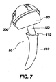
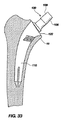
図7〜図27を全般的に参照すると、本開示は、股関節インプラント50に関する可能性があり、特に、大腿骨10の内側近位部分18に適切に荷重を掛けるようになされた大腿骨構成要素110に関する可能性がある。本明細書に記載され、開示される独特な幾何学的構造特徴を利用することにより、股関節の大腿骨側に掛けられる荷重は、大腿骨10の内側近位部分18に適切に分配されることが可能であり、それにより、その位置の骨強度を維持する。
Referring generally to FIGS. 7-27, the present disclosure may relate to the
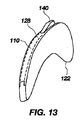
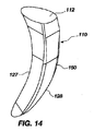
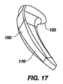
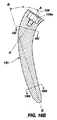
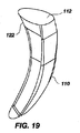
本開示による大腿骨構成要素110のいくつかの実施形態があり、そのすべてが本開示の主要な特徴を共有する。大腿骨構成要素110の(側鰭幹(lateral fin stem)として知られている)第1の実施形態が、図9〜図13及び図26〜図27に示されている。それに対して、大腿骨構成要素110の(T背面幹または翼背面幹として知られている)第2の実施形態が、図14〜図19及び図22〜図23に示されている。大腿骨構成要素110の他の実施形態が、図20〜図21及び図24〜図25に示されている。
There are several embodiments of the
ここで、本開示の全実施形態及び図9〜図19に共通の特徴を具体的に参照すると、大腿骨構成要素または幹構成要素110は、近位本体部分または近位本体構成要素120と、遠位幹部分または遠位幹構成要素130とを含んでいてもよい。近位本体部分120は、末端フレア部122が大腿骨の内側距部分に内部で接触し、それにより、上記幹構成要素110からの荷重を骨に分配することを可能にするのに十分な距離にわたって、幹構成要素110の近位端124で広がる末端フレア部(terminal flare portion)122を含んでよい。末端フレア(terminal flare)122は、例えば図28〜図31に示された自由な少なくとも部分的に円周の縁で終端してもよい。換言すれば、末端フレア部122は、大腿骨に対して内部に配置されるようになされてもよく、襟なし幹とみなされてもよい。したがって、本明細書で使用される句「末端フレア部」は、前述の特徴を指すものとし、また、自由な少なくとも部分的に円周の縁または縁部分で終端するフレア部に対して、上記少なくとも部分的に円周の縁または縁部分より遠くに放射状に延在する装置もしくは特徴に繋がっていない場合、そうでなければそれらに直接的に取り付けられていない場合のいずれかの場合もそのように呼ぶものとする。したがって、末端フレア部を有する襟なし近位部分を有するインプラントは、大腿骨との接触を大腿骨の内部に限定するように、大腿骨の外部に接触するように作用するであろう構造を備えずに、さらに、上記末端フレア部の終端部から上方かつ放射状に外側に存在する、大腿骨の部分に接触するように作用するであろう襟または他の構造を備えずに、構成され、配置される。
Referring now specifically to all embodiments of the present disclosure and features common to FIGS. 9-19, the femoral component or
一方、図5に示された外側襟20または襟20を含む幹は、襟の存在による末端フレア部ではなく、骨に対して外部に配置されてもよく、これにより、骨に対して外部から荷重を掛けるように作用していてもよい。外側襟20の別の例は、図6に示されており、骨に対して内部に(外部にではなく)配置されるようになっていてもよい末端フレア部122と同じではない。外側襟20は、骨の切除面に軸方向、下方向の荷重を掛けるようになっていてもよく、大腿骨の内側距部分に荷重を掛けなくてもよい。一方、大腿骨の内側近位部分18の遥かに大きな部分に荷重が掛けられ、これにより、骨のその部分が再吸収する危険性を低減し得るように、末端フレア部122は、大腿骨10の内側近位部分18に内部で荷重を掛けるように機能していてもよい。
On the other hand, the
図7を参照すると、本開示の組織温存インプラント50は、頭部構成要素90と、頸部構成要素100と、幹構成要素110とを含んでいてもよい。インプラント50の種々の構成要素は、チタン及びその合金、ならびにクロムコバルト及びクロムコバルトを含む合金等のインプラントグレード合金(implant grade alloys)を含む、種々の材料から製造されていてもよい。当然のことながら、インプラント50及びその種々の構成要素は、限定なくかつ本開示の範囲から逸脱することなく、任意の生体適合性材料から製造されていてもよい。
With reference to FIG. 7, the tissue-sparing
頭部構成要素90は、一般に、例えば、寛骨臼構成要素300の一部として形成された、頭部構成要素90に対向して位置する凹面と関節結合を成すための凸面であってもよい。換言すれば、頭部構成要素90は、人工股関節インプラント50の寛骨臼構成要素300と関節結合するような構成及び寸法であってもよい。
The
ここで、図28〜図36を参照すると、頭部構成要素90は、モジュール式であってもよく、または、頸部構成要素100に対して一体成形部品として形成されていてもよい。モジュール式である場合、頭部構成要素90は、(図32に最もよく示された)凹部95を含んでいてもよい。凹部95は、先細嵌合(tapered fitting)で頭部構成要素90を頸部構成要素100に取り付ける際に使用するために、先細側壁95aにより画定されていてもよい。凹部95は、一体成形による実施形態ではモジュールの結合が不要なので、(頸部構成要素100に対して)モジュール式による実施形態に存在し得るが、一体成形による実施形態には存在し得ないことは言うまでもない。
Referring now to FIGS. 28-36, the
モジュール式による実施形態では、頸部構成要素100は、(図32に最もよく示された)頭部構成要素90の凹部95内に挿入可能であってもよい(図32及び図36に最もよく示された)先細端部108を含んでいてもよく、これにより、頭部構成要素90を、モース先細摩擦嵌合(morse tapered friction fit)を介してモジュール式頸部構成要素100に固定する。例えば、頸部構成要素100の先細端部108及び頭部構成要素90の凹部95は、それぞれ略円筒形状でもよく、互いに嵌め合い係合するように先細りになっていてもよい。端部108と凹部95の適合する先細壁95aとの間の先細嵌合は、12:14の先細比を含んでいてもよい。ただし、本開示の範囲から逸脱することなく、他の先細比が利用されてもよい。当然のことながら、そのような先細結合は、モジュール式結合の一例にすぎない。モジュール式結合は、整形外科分野では周知であり、本開示の精神または範囲から逸脱することなく、頭部構成要素90を頸部構成要素100に取り付けるために、任意の型のモジュール式結合が使用されてもよい。
In a modular embodiment, the
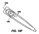
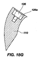
(図28〜図31に最もよく示された)別の実施形態では、頭部構成要素90は、頭部構成要素90が頸部構成要素100に対してモジュール部品である代わりに、頸部構成要素100と共に一体成形部品として形成されていてもよい。換言すれば、唯一のモジュール式結合が、幹構成要素110の近位本体部分120の上面に形成された凹部126にモジュール式に取り付けられる頸部構成要素100の遠位端102に対して存在するように、頭部構成要素90は、頸部構成要素100と共に単一の一体成形部品として形成されるかまたは製造されていてもよい。即ち、2つの要素は一体鋳造構造で形成されていてもよい。凹部126は、図18A、図18C、図18F、図18G及び図18Hに最もよく示されている。
In another embodiment (best shown in FIGS. 28-31), the
当然のことながら、頸部構成要素100は、頭部構成要素90に対して一体鋳造かモジュール式による実施形態かを問わず、頭部構成要素90の変形及び横方向のオフセットを改良または修正するために、長さが可変で、角度が可変であってもよい。頭部構成要素90の変形及び横方向のオフセットを修正する能力は、患者の自然な解剖学的特徴の復元を可能にする。さらに具体的には、頭部構成要素90及び頸部構成要素100は、一体鋳造かモジュール式かを問わず、右もしくは左の股関節に使用され得る差し障りのない方法で製造されてもよく、即ち患者の左股関節に使用される左側インプラントとして、もしくは患者の右股関節に使用される右側インプラントとして製造されていてもよい。このように、頸部構成要素100は、頭部構成要素90に対して一体鋳造かモジュール式かを問わず、患者の脚の長さ、内反及び外反の向き、ならびに前傾及び後傾、または全3つの組合せに影響を及ぼし得る、種々の長さ及び種々の型で利用可能であってもよい。
Of course, the
さらに、頸部構成要素は、頭部構成要素90に対して一体鋳造かモジュール式かを問わず、骨幹106を含んでよく、該骨幹は、偏らない頸部構成要素100の中心頸部軸A−Aに対して略直立又は軸方向に形成されていてもよい(図35に最もよく示されている)。あるいは、骨幹106は、(図35に破線で示された)角度Δを形成するように骨幹106がモジュール式付属品104(図35参照)交わる接合部107で曲がっていてもよい。角度Δは、曲がった骨幹106の(図35にC−C線及びC’−C’線で示された)中心軸と中心頸部軸A−Aとにより形成されていてもよい。該中心頸部軸は、図35に示すように、モジュール式付属品104の中心を通って延在していてもよい。角度Δまたは角度Δ’は、約4度から約24度(またはこの範囲内の任意の角度)までの範囲内で、さらに具体的には約4度から約8度の範囲の間で形成されていてもよい。種々の角度が、接合部の異なる回転中心をもたらすことは言うまでもない。
Further, the cervical component may include a
頭部構成要素90のどちらの実施形態が利用または選択されるかを問わず、即ち、頸部構成要素100に対してモジュール式であるかまたは一体鋳造であるかを問わず、頭部構成要素90は、直径約22ミリメートルから約60ミリメートルまでの間の大きさにされていてもよく、22ミリメートルと60ミリメートルとの間のすべての大きさを含んでいてもよい。例えば、図28〜図31に示すように、頭部構成要素90は特大であってもよく、直径約28ミリメートルから約60ミリメートルまでの範囲内であってもよく、さらに具体的には、直径約32ミリメートルと約60ミリメートルとの範囲の間であってもよい。より大きな頭部直径は、(図7に最もよく示された)寛骨臼構成要素300の内部で大腿骨構成要素110全体の安定性を増加させるように機能することができる。
Regardless of which embodiment of
当然のことながら、頸部構成要素100は、頭部構成要素90に対して一体鋳造構造の部品であるかモジュール式構造の部品であるかを問わず、前傾であってもよい。前傾及びオフセットは、本開示の特徴により、特定の手術中に、患者にとって最良の適合を作り出すために外科医により調整されることができる。インプラントのモジュール部品等、即ち、頭部構成要素90及び頸部構成要素100、の大きさ及び形状は、オフセットに影響を及ぼし得ることに留意すべきである。同様に、頭部構成要素90と頸部構成要素100との一体鋳造による実施形態の大きさ及び形状もまた、オフセットに影響を及ぼし得る。このように、前傾ならびに頭部の大きさ及び形状は、オフセットを増大させるかまたは変動させ得る。このオフセットは、股関節内部の長手方向幹軸と回転中心との間の距離である。例えば、より大きな頭部125を使用することが、回転中心と長手方向幹軸との間の距離を広げ、これにより、オフセットを増大させることができる。
Of course, the
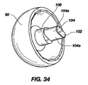
図28〜図31に示された頭部構成要素90は、凸形状の外面部92と、凸形状の外面部92の実質的に反対側に形成された凹領域94とを含んでいてもよい。凹領域94は、頭部構成要素90の周縁または基部97からある距離で延在し、かつ上部内面98で終端する(図28及び図31に最もよく示された)内側壁96により画定されていてもよい。
The
ここで、一体鋳造頭部/頸部実施形態の頸部構成要素100を参照すると、頸部100は、その遠位端102にモジュール式付属品104を含んでいてもよい。当然のことながら、モジュール式付属品104は、本開示の範囲から逸脱することなく、当該技術分野で既知のまたは既知となる可能性のある任意のモジュール式付属品であってもよい。モジュール式付属品104の一例示的実施形態は、図34に示された略長方形の横断面形状を含み得る楕円形の横断面形状を有する。
Referring now to the
頸部構成要素100の別の例示的実施形態は、頭部構成要素90に対して一体鋳造実施形態かモジュール式実施形態かを問わず、図34〜図36に示された逆砲耳形状を有していてもよい。どちらの実施形態においても、頸部構成要素100は、骨幹106を含んでいてもよく、該骨幹は、本質的に円筒形であるかまたは他の形状で成形されていてもよい。頸部構成要素100はまた、モジュール式付属品104を含んでいてもよく、該モジュール式付属品は、近位本体部分120の凹部126内に受容されていてもよい。モジュール式付属品104は、幹構成要素110の近位本体部分120に形成された凹部126の形状に合致するように成形されていてもよい(図34〜図36に最もよく示された)2つの略平坦側面部分104aを含んでいてもよい。横断面では、付属品部品104は楕円形に成形されていてもよく、より具体的には、長方形に成形されていてもよい。モジュール式付属品104はまた、先細になっていてもよく、同様に先細になっていてもよい凹部126の側壁126aに対係合していてもよい。また、他の横断面形状が、本開示の精神または範囲から逸脱することなく、付属品部品104の形状として利用されていてもよいことは言うまでもない。
Another exemplary embodiment of the
図33及び図33Aを参照すると、代替の実施形態では、頸部構成要素100のモジュール式付属品104は、頸部構成要素100を凹部126に取り付けるために(図33Aに最もよく示された)二重先細り(double taper)104bを含んでよい。凹部126は同様に成形されてもよく、頸部構成要素100の二重先細り104bと凹部126の二重先細側壁126bとの間に対係合があり得るように、二重先細(double tapered)側壁126bを含んでよいことは言うまでもない。頸部構成要素100はまた、割出し特徴(indexing feature)を含んでよく、該割出し特徴は、凹部126の側壁126bの対応する歯126cと噛み合うことができる一連の歯104cの形態であり、頭部構成要素90及び頸部構成要素100が、複数方向の配置のうち、1つの向きに配置されることを可能にする。当然のことながら、頸部構成要素100は、凹部126内部の例えば12の様々な位置の1つに配置されると、前傾の角度が、外科手術中に外科医により修正され調整され得るように、前傾であってもよい。
33 and 33A, in an alternative embodiment, the
このように、頸部構成要素100は、幹構成要素110の凹部126内への挿入のために構成され、特定の寸法に作られてもよく、かつ頸部構成要素100をそれによって幹構成要素110に固定する、付属品104を含んでよい。頸部構成要素100は、頸部構成要素100を幹構成要素110に固定する手段により、幹構成要素110に固定され、取り付けられていてもよい。当然のことながら、頸部構成要素100を幹構成要素110に固定する手段は、本開示の精神または範囲から逸脱することなく、当該技術分野で既知のまたは当該技術分野で将来的に既知となる可能性のある、任意の種類のモジュール式結合であってもよい。したがって、頸部構成要素100を幹構成要素110に固定する手段は、本開示の精神または範囲から逸脱することなく、先細結合と、鍵穴式結合(key and hole connection)と、差込み結合と、または他のモジュール式結合とを含んでよい。
In this manner, the
図18E及び図35を参照すると、モジュール式頸部構成要素100は、図35に最もよく示されている通り、頸部構成要素100の中心を通って延在し得る頸部軸A−Aを含んでよい。頸部軸A−Aは、例えば、頸部構成要素100の連続横断面の連続的な幾何学的重心(geometric centroid)を二等分する想像線であってもよい。ただし、頸部軸A−Aはまた、頸部構成要素100の連続的な幾何学的重心断面(geometric centroid sections)を二等分する線を指していてよく、句「重心断面」は、上記横断面の33%を占めるとともに、上記横断面の上記幾何学的重心を含む、横断面の一部を指す。当然のことながら、頸部構成要素100は、モジュール式頸部構成要素(図32)であってもよく、または頸部構成要素100は、一体鋳造頭部/頸部実施形態(図34)では、頭部構成要素90と一体的に形成されていてもよく、もしくは一体鋳造幹実施形態では、幹構成要素110と一体的に形成されていてもよい。モジュール式頸部実施形態では、幹構成要素110は、頸部構成要素100に取付け可能であってもよく、幹構成要素110は、図18Eに示すように、長手方向に延在し、幹構成要素110の最遠位端の中心を通る遠位幹軸B−Bを含んでよい。幹軸B−Bは、例えば、幹構成要素110の連続横断面の連続的な幾何学的重心を二等分する想像線であってもよい。ただし、幹軸B−Bはまた、幹構成要素110の連続的な幾何学的重心断面を二等分する線を指していてもよく、句「重心断面」は、上記横断面の33%を占めるとともに、上記横断面の上記幾何学的重心を含む、横断面の部分を指す。
Referring to FIGS. 18E and 35, the modular
当然のことながら、上記幹構成要素110(モジュール式頸部実施形態においてか一体鋳造実施形態においてかを問わず)に取り付けられた場合の頸部軸A−Aと遠位幹軸B−Bとの交差により、角度αが形成されていてもよい。角度αは、約45度と約60度(または該範囲内の任意の角度)との範囲内であってもよく、角度αは、自然大腿骨10の大腿骨頸部の自然な内側湾曲を模るように構成されていてもよい。さらに具体的には、角度αは、約50度から約55度までの範囲内であってもよい。
Of course, the cervical axis A-A and the distal trunk axis BB when attached to the stem component 110 (whether in the modular cervical or integral casting embodiment) The angle α may be formed by the intersection of. The angle α may be in the range of about 45 degrees and about 60 degrees (or any angle within the range), where the angle α is the natural medial curvature of the femoral neck of the
当然のことながら、幹構成要素110の湾曲の増大が、より大きな角度αをもたらし得るように、角度αは、幹構成要素110の内側湾曲に正比例していてもよい。幹構成要素110の内側湾曲は、近位大腿骨10の頸部温存式切除、及び大腿骨10の内側近位部分18の自然内側湾曲を模る幹構成要素110の必要性に因り、幹構成要素110の最近位3分の1に対して実態があってもよい。
Of course, the angle α may be directly proportional to the inner curvature of the
自然大腿骨10は、近位内側距領域にかなりの内側湾曲を含むため、大腿骨10の自然頸部14が温存された場合、頸部温存インプラント50は、その位置に自然大腿骨10の湾曲を模る必要がある可能性がある。内側面上の自然大腿骨10の湾曲を模っておらず、それに倣っておらず、それに合致しておらず、またはそれを模倣していない場合に、インプラント50の不全が生じる可能性があることは言うまでもない。既知の頸部温存装置の不全の理由の少なくとも1つは、内側湾曲の欠如、及び大腿骨10の近位内側距領域の適切な荷重の欠如に因る。換言すれば、自然大腿骨10の内側距領域の自然内側湾曲に類似または実質的に類似し得る、大腿骨構成要素110のそのような実質的な内側湾曲なしに、大腿骨構成要素110は、大腿骨10の内側距に適切に荷重を掛けることができず、結果的に、骨の再吸収及び最終的なインプラント不全を引き起こす。
Because the
ここで、本開示の種々の幹構成要素110及び図7〜図31に示された各実施形態を参照すると、全般的に、幹構成要素110は、頸部100が幹構成要素110に取り付けられた場合に、頸部軸A−Aに略垂直な平面、即ちそれを実質的に横断する平面、に形成されていてもよい上面112を含み得る。当然のことながら、上面112は、前述の頸部軸A−Aに対して完全に垂直に形成されなくてもよく、代わりに、頸部軸A−Aに対して斜めに形成されていてもよい。上面112は、幹構成要素110の近位端部124に形成されていてもよい。
Referring now to the
頸部構成要素100は、幹構成要素110に対してモジュール式であってもよく、そうである場合、幹構成要素110の上面112は、前述の凹部126を含んでよい。該凹部は、頭部構成要素90が頸部構成要素100に対してモジュール式か否かを問わず、頸部構成要素100をその中に受容するように構成され、特定の寸法に作られていてもよい。
The
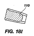
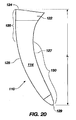
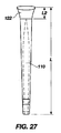
図20〜図21を具体的に参照すると、幹構成要素110は、前面部114と、後面部116と、内側面部分127と、外側面部分128と、近位本体部分120と、遠位幹部130とを含んでよい。幹構成要素110は、距離「L」で表され、約150ミリメートル未満であってもよい短縮された幹長を含んでよい。当然のことながら、幹構成要素110の長さ「L」は、図20に示すように、幹構成要素110の最近位端124から幹構成要素110の最遠位端129まで測定されていてもよい。さらに具体的には、幹構成要素110の長さ「L」は、約100ミリメートルから約120ミリメートルまでの範囲内であってもよい。
Referring specifically to FIGS. 20-21, the
さらに、当然のことながら、大腿骨構成要素110は、(図5に示す)従来の幹より実質的に短い長さの、遠位幹部130を含むようになされていてもよい。換言すれば、本開示の遠位幹部130の長さは、頸部温存式切除と併せて使用するために、従来の幹より短くてもよい。
Further, it should be appreciated that the
当然のことながら、前面部114及び後面部116はそれぞれ、股関節内のねじり力に抵抗する際に助けとなり得る平面118を含んでよい。平面118は、幹構成要素110が患者の身体内に埋め込まれた場合に、該幹構成要素110の前面または後面に沿って存在し得る平面により画定されていてもよい。このように、平面118は、実質的に平面または水平であってもよい。当然のことながら、略平坦面または平面118は、(図21に示すように)実質的に幹構成要素110の全長「L」に沿って延在していてもよく、またあるいは、平面118は、幹構成要素110の大部分の長さ「L」に沿って延在していてもよい。前面部114及び後面部116の平面118は、前面部114及び後面部116の先端が丸い形状に因り、幹構成要素110にねじり安定性を与えるように機能し得る。前面部114及び後面部116の先端の丸さは、平面118に対してのみであってもよいことに留意すべきであり、前面部114及び後面部116は回避するために丸い角及び縁を含み得ることに留意すべきである
しかし、そのような平面118は、幹構成要素110上に存在しなくてもよく、必要でない場合があることは言うまでもない。代わりに、前面部114及び後面部116はそれぞれ、本開示の精神または範囲から逸脱することなく、湾曲した外形または凸状の外形を含んでよい。当然のことながら、平面118が存在しない場合、股関節インプラント及び特に大腿骨構成要素110においてはねじり力が非常に一般的であるので、ねじり安定性を増大させるためにその他の特徴が幹構成要素110に付加されていてもよい。
Of course, the
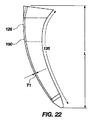
幹構成要素110は、幹構成要素110の内側面127上に(弧125で表す)湾曲をさらに含んでよい。該湾曲は、図18B及び図22に示された内側面127上に幹構成要素110の大部分の長さ「L」に沿って延在していてもよい。内側湾曲は、複数の異なる湾曲半径を含んでよく、(図18Bに最もよく示す)少なくとも3つの異なる湾曲半径を含んでよい。個々の湾曲半径はそれぞれ、幹構成要素110の近位端124から幹構成要素110の遠位端129まで内側湾曲に沿って増大していてもよい。当然のことながら、内側湾曲は、自然大腿骨10の大腿骨頸部の自然内側湾曲を模るように構成され、特定の寸法に作られていてもよい。
The
換言すれば、符号R1、R2、及びR3で図18Bに示された内側湾曲の種々の湾曲半径は、R1が最も小さい湾曲半径を有するように、R2がR1より大きい湾曲半径を有するように、R3がR1及びR2の両方より大きい湾曲半径を有するように、増大してもよい。このように、R3は、内側湾曲に沿って最大の湾曲半径を表し得る。当然のことながら、R1は、幹構成要素110の最近位端124の最も近傍に配置されてもよく、R2がその後に続いてもよく、R2は、幹構成要素110の内側面127の正中線の最も近傍に配置されてもよく、R2にR3が続いてもよく、R3は、幹構成要素110の遠位端129の最も近傍に配置されていてもよい。
In other words, the various bend radii of the inner bend shown in FIG. 18B at R1, R2, and R3 are such that R2 has a bend radius greater than R1, such that R1 has the smallest bend radius. It may be increased so that R3 has a larger radius of curvature than both R1 and R2. Thus, R3 may represent the largest radius of curvature along the inner curvature. Of course, R1 may be located nearest the
図18Bに示す特定の例により、R1で表された半径は、約1.27から約2.54cmまで(約0.5から約1.0インチまで)の範囲内であってもよく、約1.905cm(約0.750インチ)であってもよい。R2で表す半径は、約5.842から約8.128cmまで(約2.3から約3.2インチまで)の範囲内であってもよく、約7.112cm(約2.8インチ)であってもよい。R3で表された半径は、約33.02から約36.83cmまで(約13.0から約14.5インチまで)の範囲内であってもよく、約35cm(約13.780インチ)であってもよい。 According to the particular example shown in FIG. 18B, the radius represented by R1 may be in the range of about 1.27 to about 2.54 cm (from about 0.5 to about 1.0 inch), and about It may be 1.0.75 cm. The radius represented by R2 may be in the range of about 5.842 to about 8.128 cm (about 2.3 to about 3.2 inches), and is about 2.8 inches. There may be. The radius represented by R3 may be in the range of about 33.02 to about 36.83 cm (about 13.0 to about 14.5 inches), and about 35 cm (about 13.780 inches). There may be.
ここで、図15を簡単に参照すると、内側面127は、内面全体に沿った(弧125で表す)実質的な湾曲を有するように表されていてもよい。ただし、実質的な湾曲125は、幹構成要素の内側面127上の大腿骨構成要素110のおおよそ最近位3分の1において、または近位本体部分120に沿って、最も顕著であってもよい。さらに、近位本体部分120に沿った弧125で表す実質的な湾曲は、大腿骨10の近位内側部分18の自然湾曲を模倣し、合致するようになされていてもよい。このように、近位本体部分120の内側部分127に沿った実質的な湾曲125は、大腿骨構成要素110上に掛けられた荷重を大腿骨10の内側近位部分18上に方向付けるように機能し得る。大腿骨構成要素110の最近位3分の1の実質的な湾曲125と末端フレア部122との組合せは、大腿骨構成要素110が大腿骨10内に埋め込まれていてもよい場合、大腿骨10の近位内側部分18に荷重を掛けるように機能し得る。
Referring now briefly to FIG. 15, the
ここで、図9〜図13及び図26〜図27を参照すると、幹構成要素110は、外側面部分128から延出する突起または側鰭140を含んでよい。突起または側鰭140は、(図1及び図2Aに最もよく示す)大腿骨10の外側皮質部分19に接触するように作用してもよい。大腿骨10の外側皮質部分19は、外側に位置する、大腿骨10の硬い高密度部分であり、外側皮質19は、図2及び図2Aに示すように、大腿骨10の近位部分で最も顕著であることは言うまでもない。突起または側鰭140は、大腿骨10のその硬い皮質部分に接触し、それにより、幹構成要素110に掛けられる可能性のあるねじり荷重に抵抗するように構成されていてもよい。したがって、図9、図11及び図26に示された通り、突起または側鰭140は、幹構成要素110の最近位3分の1内に完全に含まれていてもよい。
Referring now to FIGS. 9-13 and 26-27, the
ここで、図26を参照すると、突起または側鰭140は、幹構成要素110の全長「L」の約15%から約25%までの範囲内であり得る長さ「L1」を有していてもよい。突起または側鰭140はまた、近位から遠位の方向に先細になっていてもよい先細面142を含んでよい。先細りは、約10度から約25度(または該範囲内の任意の角度)の範囲内であり得る角度βを有していてもよいことが分かるであろう。
Referring now to FIG. 26, the protrusions or
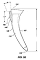
ここで、図14〜図19及び図22〜図23を参照すると、側鰭140の代替の実施形態では、幹構成要素110は、外側面部分128が湾曲していてもよいように、湾曲し得る略平坦面150を外側面部分128上に含んでよい。外側面部分128の平坦湾曲面150は、翼背面またはT背面として成形されてもよく、幹構成要素110の大部分の長さ「L」の全体にわたって延在していてもよい。外側面部分128の略平坦面150は、前後方向にかつ前面部114及び後面部116を越えて外側に延出していてもよい(図16、図18及び図23に最もよく示されている)ことを理解されたい。さらに、略平坦面150は、幹構成要素110の大部分の長さ「L」に沿って延在して、それにより、幹構成要素110が大腿骨10内に埋め込まれた場合に、幹構成要素110にねじり安定性をもたらすための平坦翼背面を形成していてもよい。
Referring now to FIGS. 14-19 and 22-23, in an alternative embodiment of the
図22及び図23に示すように、平坦翼背面150は、幹構成要素110の厚さ「T」の約5%から約25%までであり得る厚さ「T1」を含んでよく、該厚さは、幹構成要素110の前面部114と後面部116との間の測定値である(図23に最もよく示されている)。
As shown in FIGS. 22 and 23, the flat wing back
幹構成要素110は、インプラント50に掛けられるねじり力に抵抗する手段を含んでよい。当然のことながら、ねじり力に抵抗する手段は、股関節内に特有の自然ねじり力に抵抗する複数の特徴であってもよい。例えば、ねじり力に抵抗する手段は、突起もしくは側鰭140であってもよく、またはそれは翼背面150であってもよく、そのどちらも、幹構成要素110の外側面128、または前面114及び後面116上の平面118上に形成されていてもよい。
The
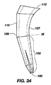
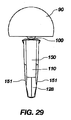
ここで、図12、図18、図21、図23、図25及び図27を参照すると、大腿骨10の内側距領域16に接触するように構成され、特定の寸法に作られていてもよい、大腿骨10の内側距部分18に内部で接触する手段、または突出部、または末端フレア部122を、幹構成要素110はさらに含んでよい。大腿骨の最大量の距骨(calcar bone)が内側に位置するため、末端フレア部122は、幹構成要素110の近位端124の近傍で、その位置で、もしくはそこから、内側の前後範囲に広がるかまたは放射状に外側に張り出して、可能な最大量の距骨に接触していてもよい。突出部または末端フレア部122は、幹構成要素110の外側面上では、内側の前面及び後面で広がるのと同程度もしくは同様に広がらなくてもよい。その結果として、インプラント50、及び具体的には大腿骨構成要素110、に掛けられる荷重が、大腿骨構成要素110から大腿骨10の内側距領域16まで内側で伝達され得る。
12, 18, 21, 23, 25, and 27, the
末端フレア部122は、幹構成要素110の最近位端124の近傍で、その位置で、またはそこから、(図18に最もよく示す)長さ「L2」にわたって張り出していてもよい。末端フレア部122の長さ「L2」は、近位端124から遠位端129まで幹構成要素110の内側面127上で測定される幹構成要素110全体の長さ「L」の約2%から約20%までの範囲内であってもよい。さらに具体的には、長さ「L2」は、幹構成要素110全体の長さ「L」の約10%から約15%までの範囲内であってもよい。特定の範囲内のすべての値は、本開示の範囲内と見做されるべきであることを理解されたい。
The
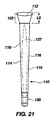
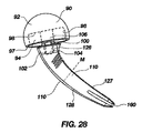
ここで、図24、図28、図30及び図31を参照すると、本開示の実施形態のいずれもが、遠位幹部130に形成されていてもよい矢状刻み溝160を含んでよいことが分かるであろう。矢状刻み溝160は、幹構成要素110の遠位部130に形成されていてもよいため、それは、幹構成要素110を2つの部分に分離または分割する。図24及び図28に示すように、2つの部分は、幹構成要素110の正中線「M」の下方に取り付けられていてもよい。換言すれば、図28、図30及び図31に示された通り、矢状刻み溝160は、幹構成要素110の内側面部分127を外側面部分128から分離し得る。
Referring now to FIGS. 24, 28, 30, and 31, any of the embodiments of the present disclosure may include a
当然のことながら、矢状刻み溝160は、幹構成要素110の遠位部130がわずかな程度または範囲で潰れ、周囲の骨を損傷することまたはそれに当接して突出することなく、遠位部130を大腿骨10の髄管内に嵌め込む際に助けとなることを可能にし得る。換言すれば、幹構成要素110の遠位部130の2つの別個の部分または面は、幹の遠位部130が随管内に進入し、骨の他の部分に接触するにつれて、互いに近づけられてもよい。このように、矢状刻み溝160は、周囲の骨を損傷することまたはそれに当接して突出することなく、幹構成要素110を大腿骨10の随管内に埋め込む際に助けとなり得る。その結果、患者の大腿部痛が緩和され得る。
Of course, the
当然のことながら、本明細書に開示された構造及び装置は、モジュール式頸部構成要素を幹構成要素に固定する手段の一例にすぎない。また、現在既知であるかまたは将来利用可能になる可能性があるモジュール式頸部構成要素を幹構成要素に固定するそれらの構造、装置、またはシステムを含む、本明細書に開示されたものと同一のまたは同等の機能を果たす、モジュール式頸部構成要素を幹構成要素に固定するいかなる構造、装置、またはシステムも、モジュール式頸部構成要素を幹構成要素に固定する手段の範囲内に入るものとされることを理解すべきである。モジュール式頸部構成要素を幹構成要素に固定する手段と同一にまたは同等に機能するいかなるものも、本要素の範囲内に入る。 Of course, the structures and devices disclosed herein are just one example of a means for securing a modular cervical component to a stem component. Also disclosed herein, including those structures, devices, or systems that secure modular cervical components that are currently known or may be available in the future to the stem components Any structure, device, or system that secures a modular neck component to a stem component that performs the same or equivalent function falls within the means of securing the modular neck component to the stem component It should be understood that Anything that functions in the same or equivalent manner as the means for securing the modular neck component to the stem component is within the scope of this element.
当然のことながら、本明細書に開示された構造及び装置は、インプラントに掛けられるねじり力に抵抗する手段の一例にすぎない。また、現在既知であるかまたは将来利用可能になる可能性があるインプラントに掛けられるねじり力に抵抗するそれらの構造、装置、またはシステムを含む、本明細書に開示されたものと同一にまたは同等に機能を果たす、インプラントに掛けられるねじり力に抵抗するいかなる構造、装置、またはシステムも、インプラントに掛けられるねじり力に抵抗する手段の範囲内に入るものとされることを理解すべきである。インプラントに掛けられるねじり力に抵抗する手段と同一にまたは同等に機能するいかなるものも、本要素の範囲内に入る。 Of course, the structures and devices disclosed herein are only one example of a means to resist torsional forces applied to the implant. Also, identical or equivalent to those disclosed herein, including those structures, devices, or systems that resist torsional forces applied to implants that are currently known or that may become available in the future It should be understood that any structure, device, or system that functions to resist the torsional force applied to the implant is within the scope of means to resist the torsional force applied to the implant. Anything that functions in the same or equivalent manner as a means of resisting torsional forces applied to the implant falls within the scope of this element.
当然のことながら、本明細書に開示された構造及び装置は、大腿骨の内側距部分に内部で接触する手段の一例にすぎない。また、現在既知であるかまたは将来利用可能になる可能性がある、大腿骨の内側距部分に内部で接触するそれらの構造、装置、または機構を含む、本明細書に開示されたものと同一にまたは同等に機能を果たす、大腿骨の内側距部分に内部で接触するいかなる構造、装置、または機構も、大腿骨の内側距部分に内部で接触する手段の範囲内に入るものとされることを理解すべきである。大腿骨の内側距部分に内部で接触する手段と同一にまたは同等に機能するいかなるものも、本要素の範囲内に入る。 Of course, the structures and devices disclosed herein are only one example of means for internally contacting the medial metric portion of the femur. Also, identical to those disclosed herein, including those structures, devices, or mechanisms that internally contact the medial distance portion of the femur that is now known or may become available in the future. Any structure, device, or mechanism that contacts the medial metric portion of the femur internally, or that performs the same function, shall fall within the scope of means of internal contact with the medial metric portion of the femur. Should be understood. Anything that functions in the same or equivalent manner as the means for internally contacting the medial distance of the femur is within the scope of this element.
前述の特徴及び組合せに基づいて、骨の内部に組織温存インプラントを外科的に配置する有用な方法は、
(a)幹構成要素と末端フレア部とを有するインプラントを提供するステップと、
(b)内側距部分を含む、患者の自然大腿骨頸部の大部分を保存しながら、インプラントを受容するために患者の近位大腿骨を外科的に準備するステップと、
(c)インプラントの幹構成要素を、外科的に準備された近位大腿骨内に挿入するステップと、
(d)荷重が幹構成要素から大腿骨の内側距部分に内側で伝達されるように、インプラントの末端フレア部を大腿骨の内側距部分に内部で接触させるステップとを含んでいてもよい。
Based on the aforementioned features and combinations, a useful method for surgically placing a tissue-sparing implant inside a bone is:
(A) providing an implant having a stem component and a terminal flare portion;
(B) surgically preparing the patient's proximal femur to receive the implant while preserving the majority of the patient's natural femoral neck, including the medial posterior portion;
(C) inserting the stem component of the implant into a surgically prepared proximal femur;
(D) contacting the distal flared portion of the implant internally to the medial metric portion of the femur such that the load is transmitted inwardly from the stem component to the medial metric portion of the femur.
当業者は、本開示の特徴によりもたらされる利点を理解するであろう。例えば、構造及び製造が簡単で、大腿骨の内側距部分に荷重を掛ける大腿骨構成要素を提供することは、本開示の潜在的な特徴である。本開示の別の潜在的な特徴は、末端フレア部(即ち襟なし拡大部)を有するそのような大腿骨構成要素を提供することである。幹部分の前面及び後面の上の平坦外側面部分を有する大腿骨構成要素を提供することは、本開示の別の潜在的な特徴である。大腿骨の内側距領域に荷重を掛けるために、短い幹長と、幹部分の最近位3分の1に実質的な内側湾曲を有する大腿骨構成要素とを提供することは、本開示の別の潜在的な特徴である。側鰭または翼背面もしくはT背面を有する大腿骨構成要素を提供することは、本開示のさらに別の潜在的な特徴である。最後に、矢状刻み溝と共に上記特徴の組合せを有する大腿骨構成要素を提供することは、本開示の潜在的な特徴である。 Those skilled in the art will appreciate the advantages afforded by the features of the present disclosure. For example, it is a potential feature of the present disclosure to provide a femoral component that is simple to construct and manufacture and that loads the medial flank portion of the femur. Another potential feature of the present disclosure is to provide such a femoral component having a terminal flare (ie, a collarless enlargement). Providing a femoral component having a flat outer surface portion over the anterior and posterior surfaces of the trunk portion is another potential feature of the present disclosure. It is another object of the present disclosure to provide a short stem length and a femoral component having a substantially medial curvature in the proximal third of the stem portion to apply a load to the medial distance region of the femur. Is a potential feature. It is yet another potential feature of the present disclosure to provide a femoral component having a scissor or wing back or T back. Finally, providing a femoral component having a combination of the above features with a sagittal kerf is a potential feature of the present disclosure.
前述した開示の詳細な説明では、本開示の種々の特徴は、本開示を簡素化する目的で、1つの実施形態にまとめられる。この開示方法は、請求項記載の開示が、各請求項に明示的に記載されたものより多くの特徴を要求する意図を反映していると解釈されるべきでない。どちらかと言えば、請求項が反映するように、発明の態様は、前述の開示された1つだけの実施形態の全特徴より少ないものによる。したがって、後続の請求項は、各請求項が本開示の別個の実施形態としてのそれ自体に基づき、参照により本明細書に本開示の詳細な説明内に援用される。 In the foregoing detailed description of the disclosure, various features of the disclosure will be combined into one embodiment for the purpose of simplifying the disclosure. This method of disclosure is not to be interpreted as reflecting an intention that the claimed disclosure requires more features than are expressly recited in each claim. Rather, as the claims reflect, aspects of the invention depend on less than all the features of only one disclosed embodiment. Thus, the following claims are hereby incorporated by reference into the detailed description of the present disclosure, with each claim standing on its own as a separate embodiment of the present disclosure.
前述の装置は、本開示の原理の応用の例証となるにすぎないことを理解されたい。多数の修正及び代替装置が、本開示の精神及び範囲から逸脱することなく、当業者により考案されてもよく、添付の特許請求の範囲は、そのような修正及び装置を包含するものとされる。したがって、本開示が図に示され、入念かつ詳細に前述されてきたが、本明細書に記載の原理及び概念から逸脱することなく、大きさ、材料、形状、形態、機能、ならびに操作、組立て及び使用の方法の変更を含むがそれらに限定されない多数の修正が施されていてもよいことが、当業者には明らかであろう。 It should be understood that the foregoing apparatus is merely illustrative of the application of the principles of the present disclosure. Numerous modifications and alternative devices may be devised by those skilled in the art without departing from the spirit and scope of the disclosure, and the appended claims are intended to cover such modifications and devices . Accordingly, although the present disclosure has been shown in the drawings and has been described in detail in detail above, it is to be understood that the size, material, shape, form, function, and operation, assembly, without departing from the principles and concepts described herein. It will be apparent to those skilled in the art that a number of modifications may be made, including but not limited to changes in the method of use.
Claims (101)
頸部構成要素であって、前記頸部構成要素を貫通して延在する頸部軸を含む、頸部構成要素と、
幹構成要素であって、前記頸部構成要素に取付け可能であり、前記幹構成要素の遠位端を貫通して延在する遠位幹軸を含む、幹構成要素と、
前記幹構成要素に取り付けられた場合の前記頸部軸と前記遠位幹軸との交差により形成され、約45度と約60度との範囲内で、自然大腿骨の大腿骨頸部の自然内側湾曲を模るように構成された、角度とを含み、
前記幹構成要素が、末端フレア部であって、前記大腿骨の内部内側距領域に接触して、荷重が前記幹構成要素から内側距領域に内側で伝達されるように構成された、末端フレア部を含む、組織温存インプラント。 In tissue-preserving implants,
A cervical component comprising a cervical axis extending through the cervical component; and
A stem component that is attachable to the cervical component and includes a distal stem shaft extending through a distal end of the stem component;
Formed by the intersection of the cervical axis and the distal stem axis when attached to the trunk component, and within the range of about 45 degrees and about 60 degrees, the natural femoral neck of the natural femur An angle configured to mimic an inward curvature,
The stem component is an end flare portion configured to contact an inner medial distance region of the femur and to transmit a load inwardly from the stem component to the medial distance region A tissue-preserving implant that includes a part.
前記幹構成要素が、前記幹構成要素の最近位端部から前記幹構成要素の最遠位端部まで測定された150ミリメートル未満の長さを有する、組織温存インプラント。 The tissue-preserving implant of claim 1,
The tissue-preserving implant, wherein the stem component has a length of less than 150 millimeters measured from the proximal end of the stem component to the distal-most end of the stem component.
前記幹構成要素の長さが、約100ミリメートルから約120ミリメートルまでの範囲内である、組織温存インプラント。 The tissue-preserving implant according to claim 2,
The tissue-preserving implant, wherein the length of the stem component is in the range of about 100 millimeters to about 120 millimeters.
前記幹構成要素が、前面と後面とであって、前記幹構成要素の大部分の長さに沿って延在する略平坦面により画定された前面と後面とを含む、組織温存インプラント。 The tissue-preserving implant of claim 1,
The tissue-preserving implant, wherein the stem component includes an anterior surface and a posterior surface, the anterior surface and the posterior surface defined by a generally flat surface extending along a major length of the stem component.
前記幹構成要素が、外側面であって、前記骨の外側皮質部分に接触するために外側面から延出する突起を備えた、前記外側面を含む、組織温存インプラント。 The tissue-preserving implant of claim 1,
The tissue-preserving implant, wherein the stem component includes an outer surface, the outer surface comprising a protrusion extending from the outer surface to contact the outer cortical portion of the bone.
前記突起が、側鰭であり、前記幹構成要素の最近位3分の1内に完全に含まれる、組織温存インプラント。 The tissue-preserving implant according to claim 5,
Tissue-preserving implant, wherein the protrusion is a scoliosis and is completely contained within the proximal third of the stem component.
前記突起が、前記幹構成要素上の近位に配置され、前記幹構成要素の全長の約15%から約25%までの範囲内の長さを有する、組織温存インプラント。 The tissue-preserving implant according to claim 5,
The tissue-preserving implant, wherein the protrusion is disposed proximally on the stem component and has a length in the range of about 15% to about 25% of the total length of the stem component.
前記突起が、近位から遠位の方向に先細になっている先細面を含み、前記先細りが、約10度から約25度の範囲内の角度を有する、組織温存インプラント。 The tissue-preserving implant according to claim 5,
The tissue-preserving implant, wherein the protrusion includes a tapered surface that tapers in a proximal-to-distal direction, the taper having an angle in the range of about 10 degrees to about 25 degrees.
前記幹構成要素が、前記幹構成要素の大部分の長さにわたって湾曲して延在する略平坦外側面部分を含む、組織温存インプラント。 The tissue-preserving implant of claim 1,
The tissue-preserving implant, wherein the stem component includes a generally flat outer surface portion that curves and extends over a major length of the stem component.
前記幹構成要素が、前面及び後面をさらに含み、前記略平坦外側面部分が、前記幹構成要素の大部分の長さに沿って前記前面及び後面を越えて延出し、それにより、前記骨の内部に埋め込まれた場合に、前記幹構成要素にねじり安定性をもたらす平坦翼背面を形成する、組織温存インプラント。 The tissue-preserving implant according to claim 9,
The stem component further includes an anterior surface and a posterior surface, and the generally flat outer surface portion extends beyond the anterior and posterior surfaces along a length of a majority of the stem component, thereby allowing the bone A tissue-preserving implant that forms a flat wing back that provides torsional stability to the stem component when implanted therein.
前記平坦翼背面が、前記幹構成要素の前記前面または後面に対して測定される前記幹構成要素の厚さの約5%から約20%までの厚さを有する、組織温存インプラント。 The tissue-preserving implant of claim 10,
The tissue-preserving implant, wherein the flat wing back has a thickness of about 5% to about 20% of the thickness of the stem component measured against the anterior or posterior surface of the stem component.
前記幹構成要素が、前記幹構成要素の遠位部分に形成された矢状刻み溝を含む、組織温存インプラント。 The tissue-preserving implant of claim 1,
The tissue-preserving implant, wherein the stem component includes a sagittal kerf formed in a distal portion of the stem component.
前記矢状刻み溝が、前記幹構成要素の最遠位部分に形成され、それにより、前記幹構成要素の内側面を前記幹構成要素の外側面から分離する、組織温存インプラント。 The tissue-preserving implant of claim 12,
A tissue-preserving implant, wherein the sagittal kerf is formed in a distal-most portion of the stem component, thereby separating the inner surface of the stem component from the outer surface of the stem component.
前記頸部構成要素が、少なくとも1つの接合部に対してモジュール式であり、前記インプラントが、頭部構成要素をさらに含む、組織温存インプラント。 The tissue-preserving implant of claim 1,
The tissue-preserving implant, wherein the cervical component is modular with respect to at least one joint, and the implant further includes a head component.
前記幹構成要素の近位端部の上面に凹部が形成され、前記凹部が、前記モジュール式頸部構成要素をその中に受容するように構成された、組織温存インプラント。 The tissue-preserving implant of claim 14,
A tissue-preserving implant, wherein a recess is formed in the upper surface of the proximal end of the stem component, the recess configured to receive the modular neck component therein.
前記モジュール式頸部構成要素が、前記幹構成要素の前記凹部内への挿入のために構成される付属部品を含み、それにより、前記モジュール式頸部構成要素を前記幹構成要素に固定する、組織温存インプラント。 The tissue-preserving implant of claim 15,
The modular cervical component includes an accessory configured for insertion of the stem component into the recess, thereby securing the modular cervical component to the stem component; Tissue-preserving implant.
前記モジュール式頸部構成要素が、前記モジュール式頸部構成要素を前記幹構成要素に固定する手段により、前記幹構成要素に固定されて取り付けられる、組織温存インプラント。 The tissue-preserving implant of claim 14,
A tissue-preserving implant, wherein the modular neck component is fixedly attached to the stem component by means for fixing the modular neck component to the stem component.
前記頭部構成要素が、先細側壁により画定された凹部を含み、前記モジュール式頸部構成要素が先細端部を含み、前記モジュール式頸部構成要素の前記先細端部が、前記頭部構成要素の前記凹部内に挿入可能であり、それにより、前記頭部構成要素を、モース先細摩擦嵌合により前記モジュール式頸部構成要素に固定する、組織温存インプラント。 The tissue-preserving implant of claim 14,
The head component includes a recess defined by a tapered sidewall, the modular neck component includes a tapered end, and the tapered end of the modular neck component is the head component. A tissue-preserving implant that can be inserted into the recess of the head, thereby securing the head component to the modular neck component with a Mohs tapered friction fit.
前記末端フレア部が、前記幹構成要素の内側面上の、前記幹構成要素の近位端から遠位端まで測定される前記幹構成要素全体の長さの約10%から約20%までの範囲内の長さにわたって、前記幹構成要素の前記近位端から放射状に張り出す、組織温存インプラント。 The tissue-preserving implant of claim 1,
The terminal flare is about 10% to about 20% of the total length of the stem component as measured from the proximal end to the distal end of the stem component on the inside surface of the stem component; A tissue-preserving implant that projects radially from the proximal end of the stem component over a length in range.
前記角度が、約50度から約55度までの範囲内である、組織温存インプラント。 The tissue-preserving implant of claim 1,
The tissue-preserving implant, wherein the angle is in the range of about 50 degrees to about 55 degrees.
前記幹構成要素の前記湾曲の増大がより大きな角度をもたらすように、前記角度が、前記幹構成要素の内側湾曲に正比例する、組織温存インプラント。 The tissue-preserving implant of claim 1,
The tissue-preserving implant, wherein the angle is directly proportional to the medial curvature of the stem component such that the increase in curvature of the stem component results in a larger angle.
前記幹構成要素の前記湾曲の増大がより大きな角度をもたらすように、前記角度が、前記幹構成要素の内側湾曲に正比例し、前記末端フレア部が凸状であり、前記幹構成要素が、
前記幹構成要素の最近位端部から前記幹構成要素の最遠位端部までが150ミリメートル未満である長さと、
前面及び後面であって、前記幹構成要素の大部分の長さに沿って延在する略平坦面により画定される、前面及び後面と、
前記幹構成要素の大部分の長さ全体にわたって湾曲し、延在する、略平坦外側面部分であって、前記幹構成要素の大部分の長さに沿って前記前面及び後面を越えて外側面部上に延在し、それにより、前記骨の内部に埋め込まれた場合に、前記幹構成要素にねじり安定性をもたらす平坦翼背面を形成する、略平坦外側面部と、
矢状刻み溝であって、前記幹構成要素の前記最遠位部分に形成され、それにより、前記幹構成要素の内側面を外側面から分離する、矢状刻み溝とをさらに含み、
前記末端フレア部が、前記幹構成要素の近位端から遠位端まで内側で測定される前記幹構成要素全体の長さの約10%から約20%までの範囲内の長さにわたって、前記幹構成要素の前記近位端から放射状に張り出す、組織温存インプラント。 The tissue-preserving implant of claim 1,
The angle is directly proportional to the inner curvature of the stem component, the end flare is convex, and the stem component is such that the increase in curvature of the stem component results in a larger angle
A length from the most proximal end of the stem component to the most distal end of the stem component of less than 150 millimeters;
An anterior surface and a posterior surface, defined by a generally flat surface extending along a length of a majority of the stem component; and
A substantially flat outer surface portion that curves and extends throughout the length of a major portion of the stem component, the outer surface portion extending beyond the front and rear surfaces along the length of the major portion of the stem component. A generally flat outer surface that extends above and thereby forms a flat wing back that provides torsional stability to the stem component when implanted within the bone;
A sagittal slot, further comprising a sagittal slot formed in the most distal portion of the stem component, thereby separating an inner surface of the stem component from an outer surface;
The terminal flare over a length in the range of about 10% to about 20% of the total length of the stem component measured inwardly from the proximal end to the distal end of the stem component; A tissue-preserving implant that projects radially from the proximal end of the stem component.
前記インプラントが、モジュール式頸部構成要素と頭部構成要素とをさらに含み、
前記幹構成要素の近位端部の上面に凹部が形成され、前記モジュール式頸部構成要素をその中に受容し、
前記モジュール式頸部構成要素が、前記幹構成要素の前記凹部内に挿入され、それにより、前記モジュール式頸部構成要素を前記幹構成要素に固定する、モジュール式付属部品を含み、
前記モジュール式頸部構成要素が、前記モジュール式頸部構成要素を前記幹構成要素に固定する手段により、前記幹構成要素に固定されて取り付けられ、
前記頭部構成要素が、先細側壁により画定される凹部を含み、前記モジュール式頸部構成要素が、先細端部を含み、前記モジュール式頸部構成要素の前記先細端部が、前記頭部構成要素の前記凹部内に挿入可能であり、それにより、前記頭部構成要素を、モース先細摩擦嵌合により前記モジュール式頸部構成要素に固定する、組織温存インプラント。 The tissue-preserving implant according to claim 22,
The implant further comprises a modular neck component and a head component;
A recess is formed in the upper surface of the proximal end of the stem component to receive the modular neck component therein;
The modular cervical component includes a modular accessory inserted into the recess of the stem component, thereby securing the modular cervical component to the stem component;
The modular cervical component is fixedly attached to the stem component by means for securing the modular cervical component to the stem component;
The head component includes a recess defined by a tapered sidewall, the modular neck component includes a tapered end, and the tapered end of the modular neck component is the head configuration. A tissue-preserving implant that is insertable into the recess of the element, thereby securing the head component to the modular neck component with a Mohs tapered friction fit.
前記幹構成要素の最近位端部から前記幹構成要素の最遠位端部までの長さが、150ミリメートル未満であり、
前面及び後面であって、前記前面及び前記後面が、前記幹構成要素の大部分の長さに沿って延在する略平坦面により画定される、前面及び後面と、
外側面であって、前記骨の外側皮質部分に接触するために前記外側面から延出する突起を備えた、外側面と、
前記突起が、前記幹構成要素の最近位3分の1内に完全に含まれ、
前記突起が、前記幹構成要素の全長の約15%から約25%までの範囲内であり、
前記突起が、近位から遠位の方向に先細になっている先細面を含み、前記先細りが、約10度から約25度までの範囲内である角度を有し、
矢状刻み溝であって、前記幹構成要素の前記最遠位部分に形成され、それにより、前記幹構成要素の内側面を外側面から分離する、矢状刻み溝と、
前記末端フレア部が、前記幹構成要素の近位端から遠位端まで内側で測定される前記幹構成要素全体の長さの約10%から約20%までの範囲内の長さにわたって、前記幹構成要素の前記近位端から放射状に張り出す、組織温存インプラント。 The tissue-preserving implant of claim 1,
The length from the most proximal end of the stem component to the most distal end of the stem component is less than 150 millimeters;
An anterior surface and a posterior surface, wherein the anterior surface and the posterior surface are defined by a substantially flat surface extending along a major length of the stem component;
An outer surface comprising a protrusion extending from the outer surface to contact an outer cortical portion of the bone;
The protrusion is fully contained within the proximal third of the stem component;
The protrusion is in a range from about 15% to about 25% of the total length of the stem component;
The protrusion includes a tapered surface that tapers in a proximal-to-distal direction, the taper having an angle in a range of about 10 degrees to about 25 degrees;
A sagittal groove, formed in the most distal portion of the stem component, thereby separating the inner surface of the stem component from the outer surface;
The terminal flare over a length in the range of about 10% to about 20% of the total length of the stem component measured inwardly from the proximal end to the distal end of the stem component; A tissue-preserving implant that projects radially from the proximal end of the stem component.
前記インプラントが、モジュール式頸部構成要素と頭部構成要素とをさらに含み、
凹部が前記幹構成要素の近位端部の上面に形成されて、前記モジュール式頸部構成要素をその中に受容し、
前記モジュール式頸部構成要素が、前記幹構成要素の前記凹部内に挿入され、それにより、前記モジュール式頸部構成要素を前記幹構成要素に固定し、
前記モジュール式頸部構成要素が、前記モジュール式頸部構成要素を前記幹構成要素に固定する手段により、前記幹構成要素に固定されて取り付けられ、
前記頭部構成要素が、先細側壁により画定される凹部を含み、前記モジュール式頸部構成要素が先細端部を含み、前記モジュール式頸部構成要素の前記先細端部が、前記頭部構成要素の前記凹部内に挿入可能であり、それにより、前記頭部構成要素を、モース先細摩擦嵌合により前記モジュール式頸部構成要素に固定する、組織温存インプラント。 25. The tissue preserving implant of claim 24,
The implant further comprises a modular neck component and a head component;
A recess is formed in the upper surface of the proximal end of the stem component to receive the modular neck component therein;
The modular cervical component is inserted into the recess of the stem component, thereby securing the modular cervical component to the stem component;
The modular cervical component is fixedly attached to the stem component by means for securing the modular cervical component to the stem component;
The head component includes a recess defined by a tapered sidewall, the modular neck component includes a tapered end, and the tapered end of the modular neck component is the head component. A tissue-preserving implant that can be inserted into the recess of the head, thereby securing the head component to the modular neck component with a Mohs tapered friction fit.
前記幹構成要素が、前面及び後面上に前記幹構成要素の略全長に延在する平面をさらに含む、組織温存インプラント。 The tissue-preserving implant of claim 1,
The tissue-preserving implant, wherein the stem component further comprises a plane extending on the anterior and posterior surfaces extending substantially the entire length of the stem component.
前記幹構成要素が、前記インプラントに掛かるねじり力に抵抗する手段をさらに含む、組織温存インプラント。 The tissue-preserving implant of claim 1,
The tissue-preserving implant, wherein the stem component further comprises means for resisting torsional forces on the implant.
ねじり力に抵抗する前記手段が、前記幹構成要素の外側面上に形成された翼背面である、組織温存インプラント。 28. The tissue preserving implant of claim 27,
The tissue-preserving implant, wherein the means for resisting torsional forces is a wing back formed on the outer surface of the stem component.
ねじり力に抵抗する前記手段が、前記幹構成要素の外側面上に形成された側鰭である、組織温存インプラント。 28. The tissue preserving implant of claim 27,
The tissue-preserving implant, wherein the means for resisting torsional force is a scissor formed on the outer surface of the stem component.
前記幹構成要素が、前記幹構成要素の最近位3分の1上に実質的な内側湾曲をさらに含む、組織温存インプラント。 The tissue-preserving implant of claim 1,
The tissue-preserving implant, wherein the stem component further comprises a substantially medial curvature on the proximal third of the stem component.
遠位幹軸を有する幹を含み、
前記幹が、近位内側突出部をさらに含み、前記突出部が、埋め込まれた場合に骨の内部内側距領域に接触するように、荷重が、前記幹構成要素から前記内側距領域まで内側で伝達されるように、前記近位内側突出部が、約70から約110度までの範囲内の前記遠位幹軸に対する角度を形成する外面を有し、
前記幹構成要素が、前記幹構成要素の大部分の長さに沿って延在する内側湾曲をさらに含み、前記内側湾曲が、前記幹構成要素の近位端から前記幹構成要素の遠位端へと増大する少なくとも3つの異なる湾曲半径を含み、前記内側湾曲が、自然大腿骨の大腿骨頸部の自然内側湾曲を模るように構成される、組織温存インプラント。 In tissue-preserving implants,
Including a stem having a distal stem axis;
The stem further includes a proximal medial protrusion, and the load is inward from the stem component to the medial distance area such that the protrusion contacts the internal medial distance area of the bone when implanted. As transmitted, the proximal inner protrusion has an outer surface that forms an angle with respect to the distal stem axis within a range of about 70 to about 110 degrees;
The stem component further includes an inner curve extending along a length of a majority of the stem component, the inner curve being from a proximal end of the stem component to a distal end of the stem component A tissue-preserving implant comprising at least three different curvature radii that increase to a distance, wherein the medial curvature is configured to mimic the natural medial curvature of the femoral neck of a natural femur.
前記幹構成要素が、150ミリメートル未満の、前記幹構成要素の上部最近位部分から前記幹構成要素の底部最遠位部分までの長さを有する、組織温存インプラント。 The tissue-preserving implant of claim 31,
The tissue-preserving implant, wherein the stem component has a length from the upper most proximal portion of the stem component to the bottom most distal portion of the stem component that is less than 150 millimeters.
前記幹構成要素が、約100ミリメートルから約120ミリメートルまでの範囲内の、前記幹構成要素の上部最近位部分から前記幹構成要素の底部最遠位部分までの長さを有する、組織温存インプラント。 The tissue-preserving implant of claim 32,
The tissue-preserving implant, wherein the stem component has a length from an upper most proximal portion of the stem component to a bottom most distal portion of the stem component within a range of about 100 millimeters to about 120 millimeters.
前記幹構成要素が、前面及び後面上に前記幹構成要素の略全長に延在する平面を含む、組織温存インプラント。 The tissue-preserving implant of claim 31,
The tissue-preserving implant, wherein the stem component includes a plane that extends substantially the entire length of the stem component on the anterior and posterior surfaces.
前記幹構成要素が、前記インプラントに掛けられるねじり力に抵抗する手段を含む、組織温存インプラント。 The tissue-preserving implant of claim 31,
A tissue-preserving implant, wherein the stem component includes means for resisting torsional forces applied to the implant.
ねじり力に抵抗する前記手段が、前記幹構成要素の外側面上に形成された翼背面である、組織温存インプラント。 36. The tissue preserving implant of claim 35,
The tissue-preserving implant, wherein the means for resisting torsional forces is a wing back formed on the outer surface of the stem component.
ねじり力に抵抗する前記手段が、前記幹構成要素の外側面上に形成された側鰭である、組織温存インプラント。 36. The tissue preserving implant of claim 35,
The tissue-preserving implant, wherein the means for resisting torsional force is a scissor formed on the outer surface of the stem component.
前記幹構成要素が、前記幹構成要素の最遠位部分に形成された矢状刻み溝を含み、それにより、前記幹構成要素の内側面を外側面から分離する、組織温存インプラント。 The tissue-preserving implant of claim 31,
A tissue-preserving implant, wherein the stem component includes a sagittal kerf formed in the distal most portion of the stem component, thereby separating the inner surface of the stem component from the outer surface.
幹構成要素であって、前記幹構成要素の全長の約2%から約20%までの範囲内の距離にわたって、前記幹構成要素の最近位部分から前側、後側及び内側方向に放射状に張り出す末端フレア部を含む、幹構成要素と、
略平坦外側面部分であって、前記幹構成要素の大部分の長さにわたって、前記幹構成要素の前面及び後面を越えて延出し、それにより、骨の内部に埋め込まれた場合に前記幹構成要素にねじり安定性をもたらす平坦翼背面を形成する、略平坦外側面部分とを含む、組織温存インプラント。 In tissue-preserving implants,
A stem component that projects radially from the most proximal portion of the stem component in an anterior, posterior and inward direction over a distance in a range of about 2% to about 20% of the total length of the stem component A stem component including an end flare portion;
A substantially flat outer surface portion that extends over the length of the majority of the stem component beyond the front and rear surfaces of the stem component, thereby providing the stem configuration when implanted within a bone A tissue-preserving implant comprising a substantially flat outer surface portion that forms a flat wing back that provides torsional stability to the element.
前記平坦翼背面が、前記幹構成要素の前記前面または後面に対して測定される前記幹構成要素の厚さの約5%から約20%までの厚さを有する、組織温存インプラント。 The tissue preserving implant of claim 39,
The tissue-preserving implant, wherein the flat wing back has a thickness of about 5% to about 20% of the thickness of the stem component measured against the anterior or posterior surface of the stem component.
前記平坦翼背面の前記厚さが、前記幹構成要素の前記厚さの約5%から約10%までである、組織温存インプラント。 41. The tissue preserving implant of claim 40,
The tissue-preserving implant, wherein the thickness of the flat wing back is from about 5% to about 10% of the thickness of the stem component.
前記末端フレア部が、前記幹構成要素の前記全長の約5%から約15%までの範囲内の距離にわたって、前記幹構成要素の前記最近位部分から前側、後側及び内側方向に張り出す、組織温存インプラント。 The tissue preserving implant of claim 39,
The end flared portion extends forward, posterior and inward from the proximal portion of the stem component over a distance in the range of about 5% to about 15% of the overall length of the stem component; Tissue-preserving implant.
前記幹構成要素が、前面及び後面上に前記幹構成要素の略全長に延在する平面を含む、組織温存インプラント。 The tissue preserving implant of claim 39,
The tissue-preserving implant, wherein the stem component includes a plane that extends substantially the entire length of the stem component on the anterior and posterior surfaces.
前記幹構成要素が、150ミリメートル未満の、前記幹構成要素の上部最近位部分から前記幹構成要素の底部最遠位部分までの長さを有する、組織温存インプラント。 The tissue preserving implant of claim 39,
The tissue-preserving implant, wherein the stem component has a length from the upper most proximal portion of the stem component to the bottom most distal portion of the stem component that is less than 150 millimeters.
前記幹構成要素が、約100ミリメートルから約120ミリメートルまでの範囲内の、前記幹構成要素の上部最近位部分から前記幹構成要素の底部最遠位部分までの長さを有する、組織温存インプラント。 The tissue preserving implant of claim 39,
The tissue-preserving implant, wherein the stem component has a length from an upper most proximal portion of the stem component to a bottom most distal portion of the stem component within a range of about 100 millimeters to about 120 millimeters.
前記幹構成要素が、前記幹構成要素の最近位3分の1上に実質的な内側湾曲を含む、組織温存インプラント。 The tissue preserving implant of claim 39,
The tissue-preserving implant, wherein the stem component includes a substantially medial curvature on the proximal third of the stem component.
前記幹構成要素が、前記幹構成要素の最遠位部分に形成された矢状刻み溝を含み、それにより、前記幹構成要素の内側面を外側面から分離する、組織温存インプラント。 The tissue preserving implant of claim 39,
A tissue-preserving implant, wherein the stem component includes a sagittal kerf formed in the distal most portion of the stem component, thereby separating the inner surface of the stem component from the outer surface.
幹構成要素であって、150ミリメートル未満の、前記幹構成要素の最近位端部から前記幹構成要素の最遠位端部までの長さを有する、幹構成要素と、
略平坦外側面部分であって、前記幹構成要素の大部分の長さにわたって、前記幹構成要素の前面及び後面を越えて延出し、それにより、骨の内部に埋め込まれた場合に前記幹構成要素にねじり安定性をもたらす平坦翼背面を形成する、略平坦外側面部分とを含む、組織温存インプラント。 In tissue-preserving implants,
A stem component having a length from the most proximal end of the stem component to the most distal end of the stem component of less than 150 millimeters;
A substantially flat outer surface portion that extends over the length of the majority of the stem component beyond the front and rear surfaces of the stem component, thereby providing the stem configuration when implanted within a bone A tissue-preserving implant comprising a substantially flat outer surface portion that forms a flat wing back that provides torsional stability to the element.
前記幹構成要素の長さが、約100ミリメートルから約120ミリメートルまでの範囲内である、組織温存インプラント。 The tissue-preserving implant of claim 48,
The tissue-preserving implant, wherein the length of the stem component is in the range of about 100 millimeters to about 120 millimeters.
前記平坦翼背面が、前記幹構成要素の前記前面または後面に対して測定される前記幹構成要素の厚さの約5%から約20%までの厚さを有する、組織温存インプラント。 The tissue-preserving implant of claim 48,
The tissue-preserving implant, wherein the flat wing back has a thickness of about 5% to about 20% of the thickness of the stem component measured against the anterior or posterior surface of the stem component.
前記平坦翼背面の前記厚さが、前記幹構成要素の前記厚さの約5%から約10%である、組織温存インプラント。 51. The tissue preserving implant of claim 50,
The tissue-preserving implant, wherein the thickness of the flat wing back is about 5% to about 10% of the thickness of the stem component.
前記幹構成要素が、前面及び後面上に前記幹構成要素の略全長に延在する平面を含む、組織温存インプラント。 The tissue-preserving implant of claim 48,
The tissue-preserving implant, wherein the stem component includes a plane that extends substantially the entire length of the stem component on the anterior and posterior surfaces.
前記幹構成要素が、前記幹構成要素の最近位3分の1上に実質的な内側湾曲を含む、組織温存インプラント。 The tissue-preserving implant of claim 48,
The tissue-preserving implant, wherein the stem component includes a substantially medial curvature on the proximal third of the stem component.
前記幹構成要素が、前記幹構成要素の最遠位部分に形成された矢状刻み溝を含み、それにより、前記幹構成要素の内側面を外側面から分離する、組織温存インプラント。 The tissue-preserving implant of claim 48,
A tissue-preserving implant, wherein the stem component includes a sagittal kerf formed in the distal most portion of the stem component, thereby separating the inner surface of the stem component from the outer surface.
幹構成要素であって、前記幹構成要素の全長の約2%から約20%までの範囲内の距離にわたって、前記幹構成要素の最近位部分から前側、後側及び内側方向に放射状に張り出す末端フレア部を含む、幹構成要素と、
突起であって、骨の外側皮質部分に接触するために、前記幹構成要素の外側面から延出する、突起とを含む、組織温存インプラント。 In tissue-preserving implants,
A stem component that projects radially from the most proximal portion of the stem component in an anterior, posterior and inward direction over a distance in a range of about 2% to about 20% of the total length of the stem component A stem component including an end flare portion;
A tissue-preserving implant comprising a protrusion that extends from an outer surface of the stem component to contact an outer cortical portion of bone.
前記突起が、前記幹構成要素の最近位3分の1内に完全に含まれる、組織温存インプラント。 56. The tissue preserving implant of claim 55,
A tissue-preserving implant, wherein the protrusion is completely contained within the proximal third of the stem component.
前記突起が、前記幹構成要素上の近位に配置され、前記幹構成要素の全長の約15%から約25%までの範囲内である、組織温存インプラント。 56. The tissue preserving implant of claim 55,
The tissue-preserving implant, wherein the protrusion is disposed proximally on the stem component and is in the range of about 15% to about 25% of the total length of the stem component.
前記突起が、近位から遠位の方向に先細になっている先細面を含み、前記先細りが、約10度から約25度までの範囲内である角度を有する、組織温存インプラント。 56. The tissue preserving implant of claim 55,
The tissue-preserving implant, wherein the protrusion includes a tapered surface that tapers in a proximal-to-distal direction, and wherein the taper has an angle that is within a range of about 10 degrees to about 25 degrees.
前記末端フレア部が、前記幹構成要素の前記全長の約5%から約15%までの範囲内の距離にわたって、前記幹構成要素の最近位端から前記前側、後側及び内側方向に張り出す、組織温存インプラント。 56. The tissue preserving implant of claim 55,
The end flared portion extends from the proximal end of the stem component in the anterior, posterior and inward directions over a distance in the range of about 5% to about 15% of the full length of the stem component; Tissue-preserving implant.
前記末端フレア部が、前記幹構成要素の略長手方向に凸状である、組織温存インプラント。 56. The tissue preserving implant of claim 55,
The tissue-preserving implant, wherein the end flare is convex in a substantially longitudinal direction of the stem component.
前記幹構成要素が、前面及び後面上に前記幹構成要素の略全長に延在する平面を含む、組織温存インプラント。 56. The tissue preserving implant of claim 55,
The tissue-preserving implant, wherein the stem component includes a plane that extends substantially the entire length of the stem component on the anterior and posterior surfaces.
前記幹構成要素が、150ミリメートル未満の、前記幹構成要素の上部最近位部分から前記幹構成要素の底部最遠位部分までの長さを有する、組織温存インプラント。 56. The tissue preserving implant of claim 55,
The tissue-preserving implant, wherein the stem component has a length from the upper most proximal portion of the stem component to the bottom most distal portion of the stem component that is less than 150 millimeters.
前記幹構成要素の長さが、約100ミリメートルから約120ミリメートルまでの範囲内である、組織温存インプラント。 The tissue-preserving implant of claim 62,
The tissue-preserving implant, wherein the length of the stem component is in the range of about 100 millimeters to about 120 millimeters.
前記幹構成要素が、前記幹構成要素の最近位3分の1上に実質的な内側湾曲を含む、組織温存インプラント。 56. The tissue preserving implant of claim 55,
The tissue-preserving implant, wherein the stem component includes a substantially medial curvature on the proximal third of the stem component.
前記幹構成要素が、前記幹構成要素の最遠位部分に形成された矢状刻み溝を含み、それにより、前記幹構成要素の内側面を外側面から分離する、組織温存インプラント。 56. The tissue preserving implant of claim 55,
A tissue-preserving implant, wherein the stem component includes a sagittal kerf formed in the distal most portion of the stem component, thereby separating the inner surface of the stem component from the outer surface.
幹構成要素であって、末端フレア部が骨の内側距部分に内部で接触するのを可能にするのに十分な距離にわたって、放射状に張り出す前記末端フレア部を有する近位端を含み、それにより、前記幹構成要素から前記骨に荷重を分配する、幹構成要素を含み、
前記幹構成要素が、150ミリメートル未満の全長を有する、組織温存インプラント。 In tissue-preserving implants,
A stem component, comprising a proximal end having said end flare radially projecting over a distance sufficient to allow the end flare to contact the medial distance portion of the bone internally; Including a stem component that distributes a load from the stem component to the bone;
A tissue-preserving implant, wherein the stem component has a total length of less than 150 millimeters.
モジュール式頸部構成要素と頭部構成要素とをさらに含む、組織温存インプラント。 A tissue-preserving implant according to claim 66,
A tissue-preserving implant further comprising a modular neck component and a head component.
凹部が、前記幹構成要素の前記近位端の上面に形成され、前記モジュール式頸部構成要素をその中に受容する、組織温存インプラント。 The tissue-preserving implant of claim 67,
A tissue-preserving implant, wherein a recess is formed in the upper surface of the proximal end of the stem component and receives the modular neck component therein.
前記凹部が、二重先細側壁を含み、前記モジュール式頸部構成要素が、前記頸部構成要素の一方の端部に配置された埋込みボルトを含み、前記埋込みボルトが二重先細りを含み、前記二重先細埋込みボルトが、モース先細摩擦嵌合により前記二重先細側壁に対係合し、それにより、前記モジュール式頸部構成要素を前記幹構成要素に固定する、組織温存インプラント。 69. The tissue preserving implant of claim 68,
The recess includes a double tapered sidewall; the modular neck component includes an embedded bolt disposed at one end of the neck component; the embedded bolt includes a double taper; A tissue-preserving implant, wherein a double tapered embedded bolt is mated to the double tapered sidewall by a Mohs tapered friction fit, thereby securing the modular neck component to the stem component.
前記凹部が複数の第1の歯を含み、前記モジュール式頸部構成要素の前記二重先細埋込みボルトが、前記モジュール式頸部構成要素を前記幹構成要素に対して割出しする複数の第2の歯を含む、組織温存インプラント。 The tissue-preserving implant of claim 69,
The recess includes a plurality of first teeth, and the second tapered embedding bolt of the modular neck component indexes a plurality of second to index the modular neck component relative to the stem component. Tissue-preserving implant, including all teeth.
前記モジュール式頸部構成要素が、前記幹構成要素の凹部内への挿入のために構成されたモジュール式付属部品を含み、それにより、前記モジュール式頸部構成要素を前記幹構成要素に固定する、組織温存インプラント。 The tissue-preserving implant of claim 67,
The modular neck component includes a modular accessory configured for insertion of the stem component into a recess, thereby securing the modular neck component to the stem component , Tissue-preserving implants.
前記モジュール式頸部構成要素が、前記モジュール式頸部構成要素を前記幹構成要素に固定する手段により、前記幹構成要素に固定されて取り付けられる、組織温存インプラント。 The tissue-preserving implant of claim 67,
A tissue-preserving implant, wherein the modular neck component is fixedly attached to the stem component by means for fixing the modular neck component to the stem component.
前記頭部構成要素が、先細側壁により画定された凹部を含み、前記モジュール式頸部構成要素が先細端部を含み、前記モジュール式頸部構成要素の前記先細端部が、前記頭部構成要素の前記凹部内に挿入可能であり、それにより、前記頭部構成要素を、モース先細摩擦嵌合により前記モジュール式頸部構成要素に固定する、組織温存インプラント。 The tissue-preserving implant of claim 67,
The head component includes a recess defined by a tapered sidewall, the modular neck component includes a tapered end, and the tapered end of the modular neck component is the head component. A tissue-preserving implant that can be inserted into the recess of the head, thereby securing the head component to the modular neck component with a Mohs tapered friction fit.
前記幹構成要素が、前記幹構成要素の略全長に共に延在する前面及び後面上に平面を含む、組織温存インプラント。 A tissue-preserving implant according to claim 66,
The tissue-preserving implant, wherein the stem component includes a plane on an anterior surface and a posterior surface that extend together substantially the entire length of the stem component.
前記幹構成要素が、約100ミリメートルから約120ミリメートルまでの範囲内の、前記幹構成要素の上部最近位部分から前記幹構成要素の底部最遠位部分までの長さを有する、組織温存インプラント。 A tissue-preserving implant according to claim 66,
The tissue-preserving implant, wherein the stem component has a length from an upper most proximal portion of the stem component to a bottom most distal portion of the stem component within a range of about 100 millimeters to about 120 millimeters.
前記幹構成要素が、前記幹構成要素の最近位3分の1上に実質的な内側湾曲を含む、組織温存インプラント。 A tissue-preserving implant according to claim 66,
The tissue-preserving implant, wherein the stem component includes a substantially medial curvature on the proximal third of the stem component.
前記幹構成要素が、前記インプラントに掛けられるねじり力に抵抗する手段を含む、組織温存インプラント。 A tissue-preserving implant according to claim 66,
A tissue-preserving implant, wherein the stem component includes means for resisting torsional forces applied to the implant.
ねじり力に抵抗する前記手段が、前記幹構成要素の外側面上に形成された翼背面である、組織温存インプラント。 The tissue-preserving implant of claim 77,
The tissue-preserving implant, wherein the means for resisting torsional forces is a wing back formed on the outer surface of the stem component.
ねじり力に抵抗する前記手段が、前記幹構成要素の外側面上に形成された側鰭である、組織温存インプラント。 The tissue-preserving implant of claim 77,
The tissue-preserving implant, wherein the means for resisting torsional force is a scissor formed on the outer surface of the stem component.
前記幹構成要素が、前記幹構成要素の最遠位部分に形成された矢状刻み溝を含み、それにより、前記幹構成要素の内側面を外側面から分離する、組織温存インプラント。 A tissue-preserving implant according to claim 66,
A tissue-preserving implant, wherein the stem component includes a sagittal kerf formed in the distal most portion of the stem component, thereby separating the inner surface of the stem component from the outer surface.
前記頸部軸が、前記頸部構成要素の連続的な幾何学的重心断面を二等分する線である組織温存インプラント。 The tissue-preserving implant of claim 1,
A tissue-preserving implant, wherein the cervical axis is a line that bisects the continuous geometric center of gravity section of the cervical component.
前記遠位幹軸が、前記幹構成要素の連続的な幾何学的重心断面を二等分する線である、組織温存インプラント。 The tissue-preserving implant of claim 1,
The tissue-preserving implant, wherein the distal stem axis is a line that bisects the continuous geometric center of gravity section of the stem component.
前記角度が、約80から約100度までの範囲内である、組織温存インプラント。 The tissue-preserving implant of claim 31,
The tissue preserving implant, wherein the angle is in the range of about 80 to about 100 degrees.
前記角度が、約85から約95度までの範囲内である、組織温存インプラント。 The tissue-preserving implant of claim 83,
The tissue-preserving implant, wherein the angle is in the range of about 85 to about 95 degrees.
前記頭部構成要素の直径が、約22ミリメートルと約60ミリメートルとの範囲の間である、組織温存インプラント。 The tissue-preserving implant of claim 14,
The tissue-preserving implant, wherein the diameter of the head component is between about 22 millimeters and about 60 millimeters.
前記頭部構成要素の直径が、約22ミリメートルと約60ミリメートルとの範囲の間である、組織温存インプラント。 The tissue-preserving implant of claim 67,
The tissue-preserving implant, wherein the diameter of the head component is between about 22 millimeters and about 60 millimeters.
幹構成要素であって、自由な少なくとも部分的に円周の縁で終端する末端フレア部を有する襟なし近位部分を含む、幹構成要素を含み、
前記末端フレア部が、前記幹構成要素の全長の約2%から約20%までの範囲内の距離にわたって、前記幹構成要素の前記近位部分の近位端から少なくとも前側、後側及び内側方向に放射状に外側に張り出す、組織温存インプラント。 In tissue-preserving implants,
A stem component comprising a collarless proximal portion having a terminal flare that terminates at a free, at least partially circumferential edge;
The terminal flared portion at least in anterior, posterior and inward directions from the proximal end of the proximal portion of the stem component over a distance in the range of about 2% to about 20% of the total length of the stem component; A tissue-preserving implant that projects radially outward.
前記幹構成要素が内側湾曲をさらに含み、前記内側湾曲が、前記幹構成要素の近位端から前記幹構成要素の遠位端へと増大する少なくとも3つの異なる湾曲半径を含み、前記内側湾曲が、自然大腿骨の大腿骨頸部の自然内側湾曲を模るように構成された、組織温存インプラント。 The tissue-preserving implant of claim 87,
The stem component further includes an inner curvature, the inner curvature including at least three different curvature radii that increase from a proximal end of the stem component to a distal end of the stem component, wherein the inner curvature is A tissue-preserving implant, configured to mimic the natural medial curvature of the femoral neck of the natural femur.
前記幹構成要素が、150ミリメートル未満の全長を有する、組織温存インプラント。 The tissue-preserving implant of claim 87,
A tissue-preserving implant, wherein the stem component has a total length of less than 150 millimeters.
前記幹構成要素が、前記幹構成要素の略全長に延在する前面及び後面上に平面を含む、組織温存インプラント。 The tissue-preserving implant of claim 87,
The tissue-preserving implant, wherein the stem component includes a flat surface on an anterior surface and a posterior surface that extend substantially the entire length of the stem component.
前記幹構成要素が、前記インプラントに掛けられるねじり力に抵抗する手段を含む、組織温存インプラント。 The tissue-preserving implant of claim 87,
A tissue-preserving implant, wherein the stem component includes means for resisting torsional forces applied to the implant.
ねじり力に抵抗する前記手段が、前記幹構成要素の外側面上に形成された翼背面である、組織温存インプラント。 The tissue-preserving implant of claim 91,
The tissue-preserving implant, wherein the means for resisting torsional forces is a wing back formed on the outer surface of the stem component.
ねじり力に抵抗する前記手段が、前記幹構成要素の外側面上に形成された側鰭である、組織温存インプラント。 The tissue-preserving implant of claim 91,
The tissue-preserving implant, wherein the means for resisting torsional force is a scissor formed on the outer surface of the stem component.
幹構成要素であって、外側面と内側面と150ミリメートル未満の全長とを含む、幹構成要素と、
側鰭であって、前記幹構成要素の前記外側面上に形成され、外科的に準備された大腿骨の外側皮質に接触するために構成され、それにより、前記インプラントに掛けられたねじり力に抵抗する、側鰭とを含む、組織温存インプラント。 In tissue-preserving implants,
A stem component comprising an outer surface and an inner surface and a total length of less than 150 millimeters;
A scissor formed on the lateral surface of the trunk component and configured to contact the lateral cortex of a surgically prepared femur, thereby torsional force applied to the implant A tissue-preserving implant that includes a scoliosis that resists.
幹構成要素であって、大腿骨の内側距部分に内部で接触する手段を含む、幹構成要素と、
前記インプラントに掛けられたねじり力に抵抗する手段とを含む、組織温存インプラント。 In tissue-preserving implants,
A stem component, comprising means for contacting the medial distance portion of the femur internally;
Means for resisting torsional forces applied to said implant.
(a)幹構成要素と末端フレア部とを有する前記インプラントを提供するステップと、
(b)内側距部分を含む患者の自然大腿骨頸部の大部分を保存しながら、前記インプラントを受容するために前記患者の近位大腿骨を外科的に準備するステップと、
(c)前記インプラントの前記幹構成要素を、前記外科的に準備された近位大腿骨内に挿入するステップと、
(d)荷重が前記幹構成要素から大腿骨の前記内側距部分に内側で伝達されるように、前記インプラントの前記末端フレア部を前記大腿骨の前記内側距部分に内部で接触させるステップとを含む、方法。 A method of surgically placing a tissue-preserving implant inside a bone, comprising:
(A) providing the implant having a stem component and a distal flare portion;
(B) surgically preparing the patient's proximal femur to receive the implant while preserving the majority of the patient's natural femoral neck, including the medial distance;
(C) inserting the stem component of the implant into the surgically prepared proximal femur;
(D) internally contacting the distal flared portion of the implant with the medial metric portion of the femur such that a load is transmitted inwardly from the stem component to the medial metric portion of the femur. Including.
前記モジュール式頸部構成要素の前記付属部品と前記幹構成要素の前記凹部とが共に、前記付属部品と前記凹部との間の対係合のための楕円形の横断面形状を含む、組織温存インプラント。 The tissue-preserving implant of claim 16,
The appendage of the modular neck component and the recess of the stem component together include an elliptical cross-sectional shape for paired engagement between the appendage and the recess Implant.
前記楕円形の横断面形状が長方形である、組織温存インプラント。 The tissue-preserving implant of claim 97,
A tissue-preserving implant, wherein the elliptical cross-sectional shape is rectangular.
前記頸部構成要素が、前記頭部構成要素と前記幹構成要素の両方に対してモジュール式であり、前記頸部構成要素と前記頭部構成要素とがそれぞれ、互いに対係合するために円筒状の先細部分を含み、前記頸部構成要素と前記幹構成要素とがそれぞれ、互いに対係合するための楕円形の先細部分を含む、組織温存インプラント。 The tissue-preserving implant of claim 14,
The cervical component is modular with respect to both the head component and the stem component, and the cervical component and the head component are each cylindrical for mating engagement with each other A tissue-preserving implant comprising a conical tapered portion, wherein the cervical component and the stem component each include an elliptical tapered portion for mating engagement with each other.
前記頸部構成要素が、前記頭部構成要素に対して単一の一体形構成で作製され、前記頸部構成要素が、前記幹構成要素のみに対してモジュール式である、組織温存インプラント。 The tissue-preserving implant of claim 14,
A tissue-preserving implant wherein the cervical component is made in a single unitary configuration with respect to the head component, and the cervical component is modular with respect to the stem component only.
前記頸部構成要素が、前記幹構成要素の前記凹部内への挿入のために構成された付属部品を含み、前記付属部品と前記凹部とが共に、互いに対係合するための楕円形の横断面を有する、組織温存インプラント。 The tissue-preserving implant of claim 100,
The cervical component includes an accessory configured for insertion of the stem component into the recess, and the accessory and the recess together are elliptical crossings for mating engagement with each other A tissue-preserving implant having a face.
Applications Claiming Priority (4)
| Application Number | Priority Date | Filing Date | Title |
|---|---|---|---|
| US90184607P | 2007-02-16 | 2007-02-16 | |
| US92213407P | 2007-04-06 | 2007-04-06 | |
| US79947407A | 2007-05-01 | 2007-05-01 | |
| PCT/US2008/002217 WO2008100639A2 (en) | 2007-02-16 | 2008-02-19 | Tissue sparing implant |
Publications (2)
| Publication Number | Publication Date |
|---|---|
| JP2010518905A true JP2010518905A (en) | 2010-06-03 |
| JP2010518905A5 JP2010518905A5 (en) | 2011-06-02 |
Family
ID=39707350
Family Applications (1)
| Application Number | Title | Priority Date | Filing Date |
|---|---|---|---|
| JP2009549648A Pending JP2010518905A (en) | 2007-02-16 | 2008-02-19 | Tissue-preserving implant |
Country Status (6)
| Country | Link |
|---|---|
| US (3) | US20080200990A1 (en) |
| EP (1) | EP2129337B1 (en) |
| JP (1) | JP2010518905A (en) |
| KR (1) | KR101531940B1 (en) |
| AU (1) | AU2008216615B2 (en) |
| WO (1) | WO2008100639A2 (en) |
Families Citing this family (18)
| Publication number | Priority date | Publication date | Assignee | Title |
|---|---|---|---|---|
| GB0207170D0 (en) | 2002-03-26 | 2002-05-08 | Mcminn Derek J W | Hip joint prosthesis |
| US7641699B2 (en) * | 2007-06-15 | 2010-01-05 | Unger Anthony S | Femoral head calcar loading prosthesis |
| IT1398533B1 (en) * | 2010-02-25 | 2013-03-01 | Permedica S P A | FEMORAL NECK PROSTHESIS. |
| ITRM20100036U1 (en) * | 2010-03-15 | 2011-09-16 | Paolo Palombi | FEMORAL PROSTHETIC STEM WITH DORSAL SOCKET |
| WO2011145008A1 (en) * | 2010-05-19 | 2011-11-24 | Symbios Orthopédie Sa | Hip stem design |
| US9301765B2 (en) | 2011-12-16 | 2016-04-05 | Chow Ip, Llc | Prosthetic femoral stem for use in high offset hip replacement |
| US8992531B2 (en) | 2011-12-16 | 2015-03-31 | Chow Ip, Llc | Prosthetic femoral stem for use in high impact hip replacement |
| US8906108B2 (en) | 2012-06-18 | 2014-12-09 | DePuy Synthes Products, LLC | Dual modulus hip stem and method of making the same |
| US9427322B1 (en) * | 2012-06-27 | 2016-08-30 | Signal Medical Corporation | Hip implant |
| FR2994077B1 (en) * | 2012-08-06 | 2015-06-12 | Univ Bordeaux 1 | CONDYLIAN PROSTHESIS FOR TEMPOROMANDIBULAR JOINT |
| US9271839B2 (en) | 2013-03-14 | 2016-03-01 | DePuy Synthes Products, Inc. | Femoral component for an implantable hip prosthesis |
| AT15407U1 (en) * | 2013-06-28 | 2017-08-15 | Implantech Medizintechnik Ges M B H | Shank for a hip joint prosthesis |
| FR3021524A1 (en) * | 2014-06-02 | 2015-12-04 | Small Bone Innovations Internat | METACARPIAN ANCHORING ROD, IN PARTICULAR FOR A TRAPEZO-METACARPIAN PROSTHESIS |
| AU2016331660A1 (en) * | 2015-09-30 | 2018-05-10 | David Phillip Kirwan | Hip prosthesis |
| CN106420118B (en) * | 2016-11-24 | 2019-02-12 | 北京科仪邦恩医疗器械科技有限公司 | Rotaryproof middle-device and hip prosthesis comprising the middle-device |
| GB201705917D0 (en) | 2017-04-12 | 2017-05-24 | Davidson Craig | Femoral trialling kit and assembly |
| GB201716107D0 (en) * | 2017-10-03 | 2017-11-15 | Depuy Ireland Ultd Co | Trial neck apparatus and method |
| CN111839821A (en) * | 2020-07-13 | 2020-10-30 | 北京市春立正达医疗器械股份有限公司 | Hip joint prosthesis for femoral neck remaining operation |
Citations (12)
| Publication number | Priority date | Publication date | Assignee | Title |
|---|---|---|---|---|
| US4004300A (en) * | 1974-10-14 | 1977-01-25 | Thomas Anthony English | Femoral prosthesis |
| US4068324A (en) * | 1977-01-19 | 1978-01-17 | Bio-Dynamics Inc. | Platform supported hip prosthesis |
| JPH05208028A (en) * | 1991-11-19 | 1993-08-20 | Bristol Myers Squibb Co | Assembly of implant with axial rod |
| JPH05212068A (en) * | 1991-09-30 | 1993-08-24 | Johnson & Johnson Orthopedics Inc | Artificial hip joint |
| US5258035A (en) * | 1992-05-29 | 1993-11-02 | Intermedics Orthopedics, Inc. | Femoral prosthesis with wedge having opposed tapers |
| JPH08502437A (en) * | 1993-02-09 | 1996-03-19 | ハウメディカ・インコーポレーテッド | Modular prosthesis for hip joint |
| US5928289A (en) * | 1996-02-08 | 1999-07-27 | Deckner; Andregeorges | Anchoring rod used particularly in prostheses |
| JP2001518821A (en) * | 1997-03-26 | 2001-10-16 | ヴァルデマール・リンク・ゲゼルシャフト・ミット・ベシュレンクテル・ハフツング・ウント・コンパニー | Hip implantable prosthesis |
| US20030163202A1 (en) * | 2002-02-06 | 2003-08-28 | Lakin Ryan C. | Modular resurfacing prosthetic |
| US20030187514A1 (en) * | 2002-03-26 | 2003-10-02 | Mcminn Derek James Wallace | Hip joint prosthesis |
| US6695884B1 (en) * | 1999-09-29 | 2004-02-24 | Biopro, Inc. | Joint implant having porous coating for mitigation of wear debris dispersion when implanted |
| JP2006523106A (en) * | 2003-01-22 | 2006-10-12 | オステオインプラント・テクロノジー・インコーポレーテッド | Intrinsic stabilization within the entire trunk |
Family Cites Families (71)
| Publication number | Priority date | Publication date | Assignee | Title |
|---|---|---|---|---|
| US3228393A (en) * | 1962-08-28 | 1966-01-11 | Arthur A Michele | Hip replacement prosthesis |
| US3938198A (en) * | 1970-08-04 | 1976-02-17 | Cutter Laboratories, Inc. | Hip joint prosthesis |
| US3871031A (en) * | 1971-12-03 | 1975-03-18 | Ceraver | Total hip prosthetic apparatus made of non-porous alumina |
| US3848272A (en) * | 1972-01-13 | 1974-11-19 | United States Surgical Corp | Artificial hip joint |
| FR2327757A1 (en) * | 1975-10-16 | 1977-05-13 | Kempf Ivan | Hip joint replacement prosthesis - has square curved shank and ball head with grooved plastics socket liner |
| CH640406A5 (en) * | 1979-10-11 | 1984-01-13 | Sulzer Ag | Hip joint prosthesis. |
| US4279042A (en) * | 1979-11-26 | 1981-07-21 | Rush-Presbyterian-St. Luke's Medical Center | Hip prosthesis |
| US4314381A (en) * | 1980-06-25 | 1982-02-09 | Lord Corporation | Hip joint prosthesis |
| CH648748A5 (en) * | 1981-02-19 | 1985-04-15 | Sulzer Ag | STRAIGHT, LEAF-LIKE SHAFT OF A JOINT OPROTHESIS. |
| US4516277A (en) * | 1981-12-08 | 1985-05-14 | Jean Butel | Article comprising and method for fabricating a hip prosthesis having a flexible multi-element femoral rod |
| US4795471A (en) * | 1982-01-18 | 1989-01-03 | Indong Oh | Conversion femoral endoprosthesis |
| US5222985B1 (en) * | 1982-04-19 | 2000-10-24 | Tranguil Prospects Ltd | Implantation of articulating joint prosthesis |
| US4406023A (en) * | 1982-04-19 | 1983-09-27 | Harris William H | Stemmed femoral component for the human hip |
| US4530114A (en) * | 1982-07-16 | 1985-07-23 | Slobodan Tepic | Total hip joint prostheses |
| US4536894A (en) * | 1983-08-04 | 1985-08-27 | Galante Jorge O | Hip prosthesis with flared porous bony ingrowth pads |
| CS238282B1 (en) * | 1983-11-30 | 1985-11-13 | Rudolf Pavlansky | Hip endoprosthesis |
| US5047062A (en) * | 1984-01-26 | 1991-09-10 | Pappas Michael J | Femoral stem-type prosthesis |
| CA1233953A (en) * | 1984-03-30 | 1988-03-15 | Robert D. Ainsworth | Orthopedic device and method of making the same |
| DE3417609A1 (en) * | 1984-05-11 | 1985-11-14 | Waldemar Link (Gmbh & Co), 2000 Hamburg | ARRANGEMENT FOR PRODUCING ANATOMICALLY APPROPRIATE ENDOPROTHESIS |
| US4642124A (en) * | 1984-06-11 | 1987-02-10 | Clemson University | Hip prosthesis |
| US4822370A (en) * | 1986-01-14 | 1989-04-18 | Orthoplant Endoprothetik | Hip joint femoral prosthesis |
| CH669106A5 (en) * | 1986-04-03 | 1989-02-28 | Sulzer Ag | LEAF-LIKE SHAFT FOR ANCHORAGE OF A HIP PROSTHESIS IN THE FEMUR. |
| US4776330A (en) * | 1986-06-23 | 1988-10-11 | Pfizer Hospital Products Group, Inc. | Modular femoral fixation system |
| ES2028879T3 (en) * | 1986-10-25 | 1992-07-16 | Gallinaro, Paolo | HIP PROTEST. |
| US4978357A (en) * | 1987-06-12 | 1990-12-18 | Mecron Medizinische Produkte Gmbh | Endoprosthesis |
| DE8708419U1 (en) * | 1987-06-15 | 1987-08-06 | Waldemar Link Gmbh & Co, 2000 Hamburg, De | |
| IT1213873B (en) * | 1987-08-03 | 1990-01-05 | Cremascoli Spa G | STRUCTURE OF HIP PROSTHESIS LIKELY TO BE EASILY ADAPTED TO THE PARTICULAR CONFORMATION OF THE COXO-FEMORAL ARTICULATION OF INDIVIDUAL PATIENTS |
| US4813963A (en) * | 1987-08-24 | 1989-03-21 | Zimmer, Inc. | Femoral component for a hip prosthesis |
| US5197989A (en) * | 1987-09-03 | 1993-03-30 | Hinckfuss Bruce W | Two stage joint prosthesis |
| DE8712578U1 (en) * | 1987-09-17 | 1987-12-17 | Howmedica Gmbh, 2314 Schoenkirchen, De | |
| US4871369A (en) * | 1987-11-23 | 1989-10-03 | Pfizer Hospital Products Group, Inc. | Long stem hip implant |
| US4919670A (en) * | 1988-02-03 | 1990-04-24 | Intermedics Orthopedics, Inc. | Modular humeral prosthesis |
| BE1001511A4 (en) * | 1988-03-15 | 1989-11-14 | Vermeire Dirk Victor | HIP prosthesis. |
| US4936863A (en) * | 1988-05-13 | 1990-06-26 | Hofmann Aaron A | Hip prosthesis |
| CH675827A5 (en) * | 1988-10-26 | 1990-11-15 | Sulzer Ag | |
| CH676664A5 (en) * | 1989-01-10 | 1991-02-28 | Sulzer Ag | |
| US4995883A (en) * | 1989-02-08 | 1991-02-26 | Smith & Nephew Richards Inc. | Modular hip prosthesis |
| US5108452A (en) * | 1989-02-08 | 1992-04-28 | Smith & Nephew Richards Inc. | Modular hip prosthesis |
| US4932974A (en) * | 1989-07-06 | 1990-06-12 | Pappas Michael J | Prosthetic device with predetermined crystal orientation |
| US4963155A (en) * | 1989-08-30 | 1990-10-16 | Zimmer, Inc. | Attachment mechanism for modular surgical products |
| US5074879A (en) * | 1990-10-26 | 1991-12-24 | Pappas Michael J | Prosthetic device with modular stem |
| US5002578A (en) * | 1990-05-04 | 1991-03-26 | Venus Corporation | Modular hip stem prosthesis apparatus and method |
| WO1991018559A1 (en) * | 1990-06-06 | 1991-12-12 | Ronald Sekel | Hip prosthesis |
| DE4040106A1 (en) * | 1990-12-12 | 1992-06-17 | Mecron Med Prod Gmbh | SCENERY PROSTHESIS |
| CH686222A5 (en) * | 1991-05-30 | 1996-02-15 | Synthes Ag | The trochanter stabilization. |
| US5156624A (en) * | 1991-09-06 | 1992-10-20 | Zimmer, Inc. | Head adaptor for hip prosthesis |
| DE9115283U1 (en) * | 1991-12-10 | 1992-02-13 | Howmedica Gmbh, 2314 Schoenkirchen, De | |
| US5755786A (en) * | 1992-09-28 | 1998-05-26 | Iolab Corporation | Ophthalmic lens with reduced edge glare |
| US5888210A (en) * | 1992-10-12 | 1999-03-30 | Draenert; Klaus | Stem of a femoral component of a hip joint endoprosthesis |
| DE69331586T2 (en) * | 1992-11-20 | 2002-10-24 | Dennis W Burke | IMPROVED FEMORAL CUFF IMPLANT |
| ATE160084T1 (en) * | 1992-12-07 | 1997-11-15 | Plus Endoprothetik Ag | SHAFT FOR A FEMURAL HIP JOINT ENDOPROSTHESIS |
| US5425768A (en) * | 1993-03-08 | 1995-06-20 | Carpenter; Charles W. | Reinforced spacer for stem-type prosthetic implants |
| US5358534A (en) * | 1993-04-29 | 1994-10-25 | Howmedica Inc. | Femoral component for a hip prosthesis |
| US5571203A (en) * | 1993-06-18 | 1996-11-05 | Masini; Michael A. | Bone-conserving hip system |
| US5593451A (en) * | 1994-06-01 | 1997-01-14 | Implex Corp. | Prosthetic device and method of implantation |
| US5653765A (en) * | 1994-07-01 | 1997-08-05 | Ortho Development Corporation | Modular prosthesis |
| US6332896B1 (en) * | 1994-07-14 | 2001-12-25 | Ortho Development Corporation | Orthopaedic implant with proximal collar |
| US5645600A (en) * | 1994-09-12 | 1997-07-08 | Bimman; Lev A. | High performance stem for arthroplasty |
| SE9403699D0 (en) * | 1994-10-28 | 1994-10-28 | Astra Ab | liner |
| DE19501995A1 (en) * | 1995-01-11 | 1996-07-18 | Effner Biomet Gmbh | Endoprosthesis |
| JPH08195703A (en) * | 1995-01-17 | 1996-07-30 | Toshiba Corp | Radio communication equipment |
| ES2176396T3 (en) * | 1995-08-25 | 2002-12-01 | Bristol Myers Squibb Co | PROTESIC IMPLANT WITH FINS. |
| FR2746001B1 (en) * | 1996-03-12 | 1998-06-12 | ORTHOPEDIC SURGERY ASSEMBLY FOR HIP PROSTHESIS WITH REMOVABLE NECK | |
| GB0007391D0 (en) * | 2000-03-27 | 2000-05-17 | Benoist Girard & Cie | Prosthetic femoral component |
| DE10036986A1 (en) * | 2000-07-29 | 2002-02-07 | Klaus Draenert | Femoral neck-preserving prosthesis |
| DE10036985A1 (en) * | 2000-07-29 | 2002-02-07 | Klaus Draenert | Femur component of artificial hip joint for cement-free implantation comprises prosthesis whose shaft has no bearing collar and whose constructional axis coincides with the femur channel axis |
| US6692530B2 (en) * | 2001-10-17 | 2004-02-17 | Hammill Manufacturing Co. | Split sleeve modular joint |
| US7494509B1 (en) * | 2002-02-04 | 2009-02-24 | Biomet Manufacturing Corp. | Method and apparatus for providing a short-stemmed hip prosthesis |
| US6755866B2 (en) * | 2002-08-20 | 2004-06-29 | Depuy Products, Inc. | Prosthetic stem with bearings |
| DE102004038281B3 (en) * | 2004-08-03 | 2006-05-11 | Endoplant Gmbh | Femoral neck prosthesis for an artificial hip joint comprises an implantable shaft which is curved and has a proximal region with a polygonal cross-section and a distal region with a round cross-section |
| AU2006201835B2 (en) * | 2005-05-09 | 2012-08-30 | Smith & Nephew, Inc. | Orthopaedic implants and methods for making the same |
-
2007
- 2007-05-01 US US11/799,747 patent/US20080200990A1/en not_active Abandoned
-
2008
- 2008-02-19 AU AU2008216615A patent/AU2008216615B2/en not_active Ceased
- 2008-02-19 EP EP08725811.7A patent/EP2129337B1/en not_active Not-in-force
- 2008-02-19 JP JP2009549648A patent/JP2010518905A/en active Pending
- 2008-02-19 WO PCT/US2008/002217 patent/WO2008100639A2/en active Application Filing
- 2008-02-19 KR KR1020097019385A patent/KR101531940B1/en active IP Right Grant
-
2014
- 2014-10-06 US US14/507,759 patent/US20150025648A1/en not_active Abandoned
-
2021
- 2021-04-05 US US17/222,892 patent/US20210290399A1/en active Pending
Patent Citations (12)
| Publication number | Priority date | Publication date | Assignee | Title |
|---|---|---|---|---|
| US4004300A (en) * | 1974-10-14 | 1977-01-25 | Thomas Anthony English | Femoral prosthesis |
| US4068324A (en) * | 1977-01-19 | 1978-01-17 | Bio-Dynamics Inc. | Platform supported hip prosthesis |
| JPH05212068A (en) * | 1991-09-30 | 1993-08-24 | Johnson & Johnson Orthopedics Inc | Artificial hip joint |
| JPH05208028A (en) * | 1991-11-19 | 1993-08-20 | Bristol Myers Squibb Co | Assembly of implant with axial rod |
| US5258035A (en) * | 1992-05-29 | 1993-11-02 | Intermedics Orthopedics, Inc. | Femoral prosthesis with wedge having opposed tapers |
| JPH08502437A (en) * | 1993-02-09 | 1996-03-19 | ハウメディカ・インコーポレーテッド | Modular prosthesis for hip joint |
| US5928289A (en) * | 1996-02-08 | 1999-07-27 | Deckner; Andregeorges | Anchoring rod used particularly in prostheses |
| JP2001518821A (en) * | 1997-03-26 | 2001-10-16 | ヴァルデマール・リンク・ゲゼルシャフト・ミット・ベシュレンクテル・ハフツング・ウント・コンパニー | Hip implantable prosthesis |
| US6695884B1 (en) * | 1999-09-29 | 2004-02-24 | Biopro, Inc. | Joint implant having porous coating for mitigation of wear debris dispersion when implanted |
| US20030163202A1 (en) * | 2002-02-06 | 2003-08-28 | Lakin Ryan C. | Modular resurfacing prosthetic |
| US20030187514A1 (en) * | 2002-03-26 | 2003-10-02 | Mcminn Derek James Wallace | Hip joint prosthesis |
| JP2006523106A (en) * | 2003-01-22 | 2006-10-12 | オステオインプラント・テクロノジー・インコーポレーテッド | Intrinsic stabilization within the entire trunk |
Also Published As
| Publication number | Publication date |
|---|---|
| KR20100014440A (en) | 2010-02-10 |
| US20150025648A1 (en) | 2015-01-22 |
| EP2129337A2 (en) | 2009-12-09 |
| EP2129337B1 (en) | 2017-01-18 |
| WO2008100639A2 (en) | 2008-08-21 |
| KR101531940B1 (en) | 2015-06-26 |
| AU2008216615A1 (en) | 2008-08-21 |
| US20080200990A1 (en) | 2008-08-21 |
| AU2008216615B2 (en) | 2014-05-22 |
| WO2008100639A3 (en) | 2008-10-09 |
| EP2129337A4 (en) | 2012-11-28 |
| US20210290399A1 (en) | 2021-09-23 |
Similar Documents
| Publication | Publication Date | Title |
|---|---|---|
| US20210290399A1 (en) | Tissue sparing implant | |
| US7125423B2 (en) | Intercalary prosthesis, kit and method | |
| US9463090B2 (en) | Modular long bone prosthesis | |
| KR101340861B1 (en) | Humeral component of a shoulder joint prosthesis | |
| JP4279132B2 (en) | Artificial femoral component with a modular sleeve | |
| US6953479B2 (en) | Orthopedic implant extension | |
| EP1402854B1 (en) | Reverse-type humeral prosthesis | |
| EP1398006A2 (en) | Duo-fixation prosthetic joints | |
| EP1913902A1 (en) | Bowed femoral sleeve | |
| EP0985386A2 (en) | Femoral stem attachment for a modular knee prosthesis | |
| US4871369A (en) | Long stem hip implant | |
| US20040254646A1 (en) | Provisional coupling mechanism | |
| JP6016781B2 (en) | Hip implant | |
| US11207197B2 (en) | Orthopaedic surgical instrument for total hip arthroplasty and associated orthopaedic surgical method of use | |
| US20190209332A1 (en) | Modular femoral prosthesis system for hip arthroplasty | |
| US20080119942A1 (en) | Short stem femoral prosthesis | |
| AU2014202481B2 (en) | Tissue sparing implant | |
| CN114786625A (en) | Implant stem for permanent fixation cement retention | |
| EP1464304A3 (en) | Prosthetic device |
Legal Events
| Date | Code | Title | Description |
|---|---|---|---|
| A711 | Notification of change in applicant |
Free format text: JAPANESE INTERMEDIATE CODE: A711 Effective date: 20100216 |
|
| A521 | Request for written amendment filed |
Free format text: JAPANESE INTERMEDIATE CODE: A821 Effective date: 20100216 |
|
| A521 | Request for written amendment filed |
Free format text: JAPANESE INTERMEDIATE CODE: A523 Effective date: 20110221 |
|
| A621 | Written request for application examination |
Free format text: JAPANESE INTERMEDIATE CODE: A621 Effective date: 20110221 |
|
| A521 | Request for written amendment filed |
Free format text: JAPANESE INTERMEDIATE CODE: A523 Effective date: 20110328 |
|
| A521 | Request for written amendment filed |
Free format text: JAPANESE INTERMEDIATE CODE: A523 Effective date: 20110411 |
|
| A131 | Notification of reasons for refusal |
Free format text: JAPANESE INTERMEDIATE CODE: A131 Effective date: 20121009 |
|
| A977 | Report on retrieval |
Free format text: JAPANESE INTERMEDIATE CODE: A971007 Effective date: 20121011 |
|
| A601 | Written request for extension of time |
Free format text: JAPANESE INTERMEDIATE CODE: A601 Effective date: 20130109 |
|
| A602 | Written permission of extension of time |
Free format text: JAPANESE INTERMEDIATE CODE: A602 Effective date: 20130117 |
|
| A521 | Request for written amendment filed |
Free format text: JAPANESE INTERMEDIATE CODE: A523 Effective date: 20130409 |
|
| A131 | Notification of reasons for refusal |
Free format text: JAPANESE INTERMEDIATE CODE: A131 Effective date: 20131008 |
|
| A601 | Written request for extension of time |
Free format text: JAPANESE INTERMEDIATE CODE: A601 Effective date: 20140107 |
|
| A602 | Written permission of extension of time |
Free format text: JAPANESE INTERMEDIATE CODE: A602 Effective date: 20140115 |
|
| A601 | Written request for extension of time |
Free format text: JAPANESE INTERMEDIATE CODE: A601 Effective date: 20140310 |
|
| A602 | Written permission of extension of time |
Free format text: JAPANESE INTERMEDIATE CODE: A602 Effective date: 20140317 |
|
| A521 | Request for written amendment filed |
Free format text: JAPANESE INTERMEDIATE CODE: A523 Effective date: 20140408 |
|
| A02 | Decision of refusal |
Free format text: JAPANESE INTERMEDIATE CODE: A02 Effective date: 20140606 |