JP2010517841A - Lock device for vehicle seat - Google Patents
Lock device for vehicle seat Download PDFInfo
- Publication number
- JP2010517841A JP2010517841A JP2009547577A JP2009547577A JP2010517841A JP 2010517841 A JP2010517841 A JP 2010517841A JP 2009547577 A JP2009547577 A JP 2009547577A JP 2009547577 A JP2009547577 A JP 2009547577A JP 2010517841 A JP2010517841 A JP 2010517841A
- Authority
- JP
- Japan
- Prior art keywords
- locking device
- spring
- lock
- safety
- safety member
- Prior art date
- Legal status (The legal status is an assumption and is not a legal conclusion. Google has not performed a legal analysis and makes no representation as to the accuracy of the status listed.)
- Granted
Links
- 230000009471 action Effects 0.000 claims description 17
- 238000013459 approach Methods 0.000 claims description 6
- 230000003993 interaction Effects 0.000 claims description 3
- 238000000034 method Methods 0.000 description 3
- 230000008569 process Effects 0.000 description 3
- 210000000078 claw Anatomy 0.000 description 2
- 230000007423 decrease Effects 0.000 description 2
- 239000000470 constituent Substances 0.000 description 1
- 230000001419 dependent effect Effects 0.000 description 1
- 238000000926 separation method Methods 0.000 description 1
Images

Classifications
-
- B—PERFORMING OPERATIONS; TRANSPORTING
- B60—VEHICLES IN GENERAL
- B60N—SEATS SPECIALLY ADAPTED FOR VEHICLES; VEHICLE PASSENGER ACCOMMODATION NOT OTHERWISE PROVIDED FOR
- B60N2/00—Seats specially adapted for vehicles; Arrangement or mounting of seats in vehicles
- B60N2/02—Seats specially adapted for vehicles; Arrangement or mounting of seats in vehicles the seat or part thereof being movable, e.g. adjustable
- B60N2/22—Seats specially adapted for vehicles; Arrangement or mounting of seats in vehicles the seat or part thereof being movable, e.g. adjustable the back-rest being adjustable
-
- B—PERFORMING OPERATIONS; TRANSPORTING
- B60—VEHICLES IN GENERAL
- B60N—SEATS SPECIALLY ADAPTED FOR VEHICLES; VEHICLE PASSENGER ACCOMMODATION NOT OTHERWISE PROVIDED FOR
- B60N2/00—Seats specially adapted for vehicles; Arrangement or mounting of seats in vehicles
- B60N2/02—Seats specially adapted for vehicles; Arrangement or mounting of seats in vehicles the seat or part thereof being movable, e.g. adjustable
- B60N2/20—Seats specially adapted for vehicles; Arrangement or mounting of seats in vehicles the seat or part thereof being movable, e.g. adjustable the back-rest being tiltable, e.g. to permit easy access
Landscapes
- Engineering & Computer Science (AREA)
- Aviation & Aerospace Engineering (AREA)
- Transportation (AREA)
- Mechanical Engineering (AREA)
- Seats For Vehicles (AREA)
- Lock And Its Accessories (AREA)
Abstract
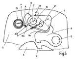
【解決手段】第1ベアリングピン(13)を中心に回動自在で第1部材(5)に移動自在に装着される第1ロック部材(11)と、第1ロック部材(11)とロック装置(1)のロック状態で相互作用する第2ロック部分(12)を設けて第1ロック部材(11)に対して移動自在な第2部材(8)と、第1ロック部材(11)に移動自在な状態で中心(Z)を有する第2ベアリングピン(19)の周りに回動自在に設けられてロック装置(1)のロック状態を維持する安全部材(15、17)と、安全部材(15、17)にポイント(P)で力(K)で作用して安全部材を第1ロック部材(11)またはストッパ(23)側に付勢するバネ(25)を備え、第1部材(5)と第2部材(8)を解除自在にロックし、力(K)が、バネ(25)により作用を受ける安全部材(15、17)の所定の角度位置で中心(Z)を通るロック装置、特に、車両座席用ロック装置。
【選択図】図5
A first lock member (11) rotatably mounted around a first bearing pin (13) and movably mounted on a first member (5), a first lock member (11) and a lock device A second lock portion (12) that interacts in the locked state of (1) is provided, and the second member (8) that is movable with respect to the first lock member (11) is moved to the first lock member (11). Safety members (15, 17) which are rotatably provided around a second bearing pin (19) having a center (Z) in a free state to maintain the locked state of the locking device (1); 15, 17) is provided with a spring (25) that acts with a force (K) at a point (P) to urge the safety member toward the first lock member (11) or the stopper (23) side, and the first member (5 ) And the second member (8) are releasably locked, and the force (K) is applied to the spring (25 Locking device through the center (Z) at a predetermined angular position of the safety member (15, 17) being acted upon by, in particular, the locking device for a vehicle seat.
[Selection] Figure 5
Description
本発明は、請求項1の前段部分の特徴を備えたロック装置に関する。 The invention relates to a locking device with the features of the front part of claim 1.
従来のロック装置では、ロック装置のロック解除時に、安全部材を第1ロック部材から離間する方向に回動してロック解除状態に保持するように設計されている。
同時に、バネによる予張力の重ね合わせによりロック装置内に存在する閉塞トルク(すなわち、ロック装置をロックするように作用するトルク)に関連して、ロック装置をロックする方向に作用する大きなトルクが、安全部材に対して加えられる場合がある。
The conventional lock device is designed to hold the safety member in the unlocked state by rotating the safety member in a direction away from the first lock member when the lock device is unlocked.
At the same time, a large torque acting in the direction of locking the locking device in relation to the closing torque present in the locking device due to the superposition of the pretension by the spring (i.e. the torque acting to lock the locking device), May be added to safety elements.
本発明の目的は、前述したような従来のロック装置を改善することである。
本発明の目的は、請求項1の特徴を備えたロック装置により達成される。
有益な改良は、従属する請求項の要旨である。
The object of the present invention is to improve the conventional locking device as described above.
The object of the invention is achieved by a locking device with the features of claim 1.
Useful improvements are the subject matter of the dependent claims.
本発明の車両座席用のロック装置では、バネによる作用を受けた安全部材をロック解除方向に向けて移動させる際に、安全部材の角度位置に応じて、力の作用ラインが中心に近づく、すなわち、バネから安全部材に対して及ぼされる力の作用ラインが安全部材を軸支するベアリングピンの中心に近づくため、バネにより安全部材に対して及ぼされるトルクが減少し、その結果、ロック解除時に必要とされるロック解除トルクを低減できる。
安全部材の少なくとも1つの角度位置では、前述したバネから及ぼされる力の作用ラインが安全部材を軸支するベアリングピンの中心を通り、その結果として、バネは安全部材に対して何らのトルクを及ぼさないように設計するのが好ましい。
ロック装置のロック解除状態で安全部材をロック解除状態に保持する必要がある場合、例えば、安全部材に設けられる制御用輪郭部分の設計を調節してバネと安全部材との間の相互作用を調整し、ロック解除状態(ロック解除方向に移動した状態)に保持された安全部材が前述した角度位置に正確に保持されるように設計しても良く、すなわち、異なる予張力を重ね合わせることにより規定されて、安全部材をロック解除状態に保持すべく加えられるトルクの全体が、最小になるように設計しても良い。
In the vehicle seat locking device according to the present invention, when the safety member that receives the action of the spring is moved in the unlocking direction, the force action line approaches the center according to the angular position of the safety member. Because the action line of the force exerted on the safety member from the spring approaches the center of the bearing pin that supports the safety member, the torque exerted on the safety member by the spring is reduced, and as a result, required when unlocking It is possible to reduce the unlocking torque.
In at least one angular position of the safety member, the line of action of the force exerted from the aforementioned spring passes through the center of the bearing pin that pivots the safety member, so that the spring exerts no torque on the safety member. It is preferable not to design.
When it is necessary to hold the safety member in the unlocked state when the locking device is unlocked, for example, the design of the control contour provided on the safety member is adjusted to adjust the interaction between the spring and the safety member In addition, the safety member held in the unlocked state (the state moved in the unlocking direction) may be designed to be accurately held at the above-mentioned angular position, that is, specified by overlapping different pretensions. Thus, the total torque applied to hold the safety member in the unlocked state may be designed to be minimal.
本発明の一実施例を図面に基づいて以下に詳細に説明する。 An embodiment of the present invention will be described below in detail with reference to the drawings.
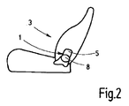
本発明の一実施例である自動車の車両座席用のロック装置1は、第1部材5を第2部材8に対して解除自在にロックするために設けられ、すなわち、衝突発生時における安全性を確保するような態様で設けられている。
これら第1部材5と第2部材8は、例えば、例えば、EP1187738B1に開示されているようなキャッチ式取り付け具を構成する取り付け部材であっても良く、あるいは、例えば、EP1334867B1に開示されるような自由に回動する機能を有してギア作動される取り付け具を構成する取り付け部材であっても良い。
本実施例においては、最後に述べた実施形態が選択されている。
しかしながら、第1部材5は、例えば、EP1373011B1に開示されるようなロック部材であっても良く、また、第2部材8は、例えば、車両座席3の背もたれまたは装着脚部を車両構造体に対してロックするために使用されるロック部材などの関連する対向部材であっても良い。
これらの開示内容は、本発明に明確に含有されている。
The locking device 1 for a vehicle seat of an automobile according to an embodiment of the present invention is provided for releasably locking the first member 5 with respect to the second member 8, that is, safety at the time of occurrence of a collision. It is provided in such a manner as to ensure.
The first member 5 and the second member 8 may be, for example, a mounting member constituting a catch-type mounting tool as disclosed in EP11887738B1, or as disclosed in EP13334867B1, for example. It may be an attachment member that constitutes a gear-operated attachment having a function of freely rotating.
In the present example, the last-described embodiment is selected.
However, the first member 5 may be a locking member as disclosed in, for example, EP13773011B1, and the second member 8 may be configured such that, for example, the backrest or mounting leg of the vehicle seat 3 is attached to the vehicle structure. It may be a related counter member such as a lock member used for locking.
These disclosures are expressly included in the present invention.
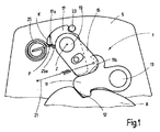
ロック装置1は、第1部材5に移動自在に、好ましくは、回動自在に装着される第1ロック部材11と、第2部材8に設けられ、特に、第2部材8に形成され、または、第2部材8に取り付けられ、または、第2部材8を形成する第2ロック部分12とを備えている。
これら第1部材5と第2部材8は、相互にロックされ、すなわち、図1に示すように、第2部材8に形成されたロック用凹部分に第1部材5に形成されたロック用突出部分を嵌合させることで相互にロックされ、第1ロック部材11と第2ロック部分12との相互作用時に、ロック装置1がロック状態となるように設計されている。
本実施例では、第1ロック部材11は、第1部材5に接続固定された第1ベアリングピン13により回動自在に装着される爪付き部材であり、ロック用爪部分を有している。
一方、第2ロック部分12は、第2部材8に形成されたロック用凹部分である。
第1ロック部材11は、第2ロック部分12から離間した側面に、ベアリング面11aを有している。
The locking device 1 is provided on a
The first member 5 and the second member 8 are locked to each other, that is, as shown in FIG. 1, the locking protrusion formed on the first member 5 in the locking concave portion formed on the second member 8. The locking device 1 is designed to be locked when the
In the present embodiment, the
On the other hand, the
The
ロック装置1は、第1安全部材15と第2安全部材17とを更に備えている。
第1安全部材15と第2安全部材17は、第1ベアリングピン13に平行に設けられる第1部材5に固定された第2ベアリングピン19に対して、特に、同一の第2ベアリングピン19に対して回動自在にそれぞれ装着されている。
第2ベアリングピン19の中心は、図1に符号Zにより示されている。
2つの第1安全部材15と第2安全部材17のうちの一方は、第2ベアリングピン19に回り止め状態で取り付けられていても良く、この場合、第2ベアリングピン19は、シャフトとしての機能を果たすように設計されている。
第1安全部材15と第2安全部材17は、第1ロック部材11側へ向けて予張力をそれぞれ受けており、また、第1ロック部材11に形成されたベアリング面11aは、第1ロック部材11と第2ロック部分12とが相互作用する際、特に、第1ロック部材11と第2ロック部分12とが相互に係合する際、または、第1ロック部材11と第2ロック部分12とが少なくとも相互に寄り添う際、第1安全部材15と第2安全部材17の回動領域に位置している。
The locking device 1 further includes a
The
The center of the second bearing
One of the two
The
第1安全部材15は、テンション部材、すなわち、押し付け部材としての機能を有し、本実施例では牽引バネとして構成された引張バネ21により予張力を受けている。
通常時、このように引張バネ21による予張力を受けた第1安全部材15が、第1ロック部材11に形成されたベアリング面11aに作用して、第1ロック部材11を第2ロック部分12に対して押し付けていることにより、ロック装置1のロック状態が維持されるように設計されている。
また、本実施例では偏心部材として構成された第1安全部材15は、自動ロック領域外の角度で、隙間を伴うことなく、ベアリング面11aに当接している。
第1部材5と第2部材8との間に非常に大きな力が作用する場合、例えば、第1部材5と第2部材8との間に非常に大きな力が作用する衝突発生時には、第1ロック部材11が第1安全部材15に対してロック解除トルク(すなわち、ロック装置1のロックを解除する方向に働くトルク)を及ぼすため、第1安全部材15が、この第1安全部材15にかけられた予張力に対抗して逆方向に回動することがある。
その結果、第1ロック部材11が、その解放方向、すなわち、ロック解除方向(換言すると、ロック装置1のロックを解除する方向)に移動する場合がある。
The
In a normal state, the
Moreover, the
When a very large force acts between the first member 5 and the second member 8, for example, when a collision occurs where a very large force acts between the first member 5 and the second member 8, the first The
As a result, the
第2安全部材17はキャッチ部材としての機能を有し、この第2安全部材17は、通常時には、短い距離、すなわち、第1ロック部材11と第2ロック部分12の歯の高さと比較して短い距離だけ第1ロック部材11に形成されたベアリング面11aから離間した状態で配置され、衝突発生時には、図1に示すように第1部材5に設けられるストッパ23に当接するように設計されている。
The
第2安全部材17は、衝突発生時に、特にロック解除トルクを及ぼすことなく、自動ロック領域内(すなわち、自動的に第1ロック部材11と第2部材8に形成された第2ロック部分12との係合状態を維持しうる領域内)の角度位置に位置して、第1ロック部材11に形成されたベアリング面11a(または、他の面)に当接することにより、そのロック解除方向に回動する第1ロック部材11を短い経路の回動後に支持するように設計されている。
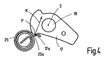
第2安全部材17は、支持された領域、すなわち、バネ25により支持される部分領域
で、例えば、第2ベアリングピン19の周りに同心的に湾曲していても良く、あるいは、第2ベアリングピン19に対して接線方向に延びていても良い。
本実施例の場合、第2安全部材17には、バネ25により予張力がかけられている。
本実施例の場合、バネ25は、平坦な螺旋バネとして構成されている。
In the event of a collision, the
The
In this embodiment, the
In the case of the present embodiment, the
ロック装置1のロックを解除する際、最初に、第1安全部材15と第2安全部材17のいずれか一方が、(第1安全部材15と第2安全部材17のいずれかが第2ベアリングピン19に回り止め状態で取り付けられた場合に)シャフトとして構成された第2ベアリングピン19により、または、第1安全部材15または第2安全部材17に取り付けられたケーブルを牽引することにより、第1ロック部材11から離間するように回動し、すなわち、開放されて(すなわち、ロック解除方向に移動して)ロック解除状態(ロック解除方向に移動した状態)が保持されるように設計されている。
第1安全部材15と第2安全部材17は、それらが、例えば、スロット・ピン・ガイド(slot-pin-guide)により移動の遅れを伴って運ばれ得るように相互に結合され、その結果、規定された空転経路の通過後に、最初に移動されない2つの第1安全部材15と第2安全部材17のうちの他方が追従して移動するように設計されているのが好ましく、換言すると、図1に示す本実施の場合、第1安全部材15に形成されたスロット部分内に第2安全部材17に形成されたガイドピン部分を入り込ませるスロット・ピン・ガイド手段により、第2安全部材17が第1安全部材15の移動から一定の遅れを伴って移動するように、第1安全部材15と第2安全部材17とが相互に結合されており、その結果、第1安全部材15に形成されたスロット部分と第2安全部材17に形成されたガイドピン部分との間に存在する隙間に起因して形成される空転経路の通過後に、初めは移動しない第2安全部材17が第1安全部材15に追従して移動するように設計されているのが好ましい。
その結果、開放される第2安全部材17が、例えば、フィンガ等により第1ロック部材11を引き上げて、第1ロック部材11を解除するように設計されているのが好ましく、換言すると、図1に示す本実施例の場合、前述したように回動して開放される第2安全部材17が、第1ロック部材11に形成されたフィンガ部分を利用して第1ロック部材11を引き上げて、第1ロック部材11をロック解除方向に回動させるように設計されている。
したがって、第1ロック部材11が、第2ロック部分12から離間する方向に移動するように設計されている。
そして、第1ロック部材11と第2ロック部分12とが、相互作用を生じない程度まで相互に離間し、ロック装置1のロックが解除されるように設計されている。
その結果、第1部材5と第2部材8とを相対的に移動させることができるように設計されている。
そして、ロック装置1のロックを解除する際にまず初めに第1ロック部材11から離間する方向に回動する第1安全部材15または第2安全部材17を解放した際には、すなわち、第1安全部材15または第2安全部材17をロック解除方向に回動させることを止めた際には、第1安全部材15または第2安全部材17に対してかけられた予張力により、第1ロック部材11は、再び、第1安全部材15からの作用を受けて、第2ロック部分12と係合するように設計されている。
When unlocking the locking device 1, first, either one of the
The
As a result, it is preferable that the
Accordingly, the
The
As a result, the first member 5 and the second member 8 are designed to be able to move relative to each other.
When the locking device 1 is unlocked, first, when the
予張力を受けた第1安全部材15と第2安全部材17をロック解除方向に向けて回動させるために必要とされるロック解除トルクは、第1安全部材15と第2安全部材17に対してかけられる予張力の特性曲線により決定され、したがって、本実施例の場合、引張バネ21とバネ25の設計により決定されるようになっている。
バネ25は、第2安全部材17に形成された制御用輪郭部分17aと相互作用し、本実施例の場合、バネ25の径方向外側端部に形成されたバネアーム部分25aが、制御用輪郭部分17aに沿ってスライドしてその位置を可変するポイントPで、制御用輪郭部分17aに当接している。
ロック装置1のロック状態において、引張バネ21は、比較的小さい力で中心Zで比較的大きい有効レバーアーム(lever arm)を伴って、第1安全部材15に作用しており、すなわち、引張バネ21は、比較的小さい力で第1安全部材15に作用しており、この引張バネ21の力の作用方向に沿った作用ラインは、中心Zから比較的大きく離間している。
バネ25は、小さい力を伴って且つ中心Zからの大きい有効距離を伴って、すなわち、バネ25は、小さい力で第2安全部材17を保持しており、このバネ25の力Kの作用方向に沿った作用ラインは、中心Zから比較的大きく離間している。
The unlocking torque required to rotate the pre-tensioned
The
In the locked state of the locking device 1, the
The
開放中、すなわち、ロック装置1のロックを解除する際に、第1安全部材15は、回動して引張バネ21の張力を増大させるように設計されている。
その結果として、引張バネ21の力が増大すると同時に、前述した有効レバーアームが減少し、すなわち、引張バネ21の力の作用方向に沿った作用ラインの中心Zからの離間距離が短くなるように設計されている。
第2安全部材17の場合、最初に、ロック装置1のロックを解除する方向に働くロック解除トルクが、バネ25に対抗して、バネ25の予張力を上回る必要がある。
そして、その後のロック解除プロセスでは、必要とされるロック解除トルクの大きさは、第2安全部材17に形成された制御用輪郭部分17aの形状、本実施例の場合、第2ベアリングピン19を中心として湾曲した制御用輪郭部分17aの部分領域の形状に起因して減少するように設計されている。
ポイントPで第2安全部材17に対して作用するバネ25による力Kの作用ライン、すなわち、力Kの作用方向、より具体的には、バネ25による力Kの作用方向に沿った直線は、第2安全部材17の角度位置に応じて、第2ベアリングピン19の中心Z、すなわち、第2安全部材17の回転軸に近づくように設計されている。
During opening, i.e., when unlocking the locking device 1, the
As a result, as the force of the
In the case of the
In the subsequent unlocking process, the required amount of unlocking torque is determined by the shape of the
The action line of the force K by the
このように、第2ベアリングピン19の周囲で第2安全部材17に及ぼされるバネ25の力Kによるトルクの特性曲線は、第2安全部材17の角度位置に応じてゼロ点に近づくように設計されている。
このゼロ点は、第2安全部材17の特定の角度位置で、本実施例の場合、ロック解除プロセスの終端で到達するように設計されている。
したがって、ロック解除プロセスの終端において、バネ25は、第2安全部材17に対してトルクを何ら及ぼさないように設計されている。
その代わりに、バネ25による力Kが、第2ベアリングピン19の中心Zを直接的に通るようになっている。
したがって、純然たる支持力だけが、第2安全部材17に対して作用している。
その結果、第1安全部材15および第2安全部材17を開放状態、すなわち、ロック解除方向に移動した状態に保持するために必要とされる全体の逆トルク、すなわち、ロック解除トルクの力を低減できる。
Thus, the characteristic curve of the torque due to the force K of the
This zero point is designed to be reached at a specific angular position of the
Therefore, at the end of the unlocking process, the
Instead, the force K by the
Therefore, only a pure support force acts on the
As a result, the overall reverse torque required to hold the
第2安全部材17に形成される制御用輪郭部分17aの設計を調節して、第2ベアリングピン19の周囲で第2安全部材17に作用するバネ25の力Kによるトルクの特性曲線を調節することで、ロック装置1のロック解除時に必要とされる力を使用者にとって快適な作動力の経路、すなわち、使用者が本発明のロック装置1を操作した際に快適であると感じる操作時の感触に対応して調節しても良い。
例えば、使用者によるロック装置1の操作時に、初めに僅かに大きな力を必要とし、その後に軽い力を必要とし、最後に大きな力を必要とするように、前述した作動力の経路を調節しても良い。
By adjusting the design of the
For example, when operating the locking device 1 by the user, the operating force path described above is adjusted so that a slightly large force is required first, a light force is required thereafter, and a large force is required finally. May be.
ロック装置1のロック解除時、すなわち、ロック装置1をロックする際には、引張バネ21は、初めに、第1安全部材15をロック方向(すなわち、ロック装置1をロックする方向)に引張する。
その後、第1安全部材15は、スロット・ピン・ガイドにより、すなわち、第1安全部材15に形成されたスロット部分を第2安全部材17に形成されたガイドピン部分によりガイドされて、第2安全部材17に沿って移動する。
第2安全部材17は、第2安全部材17に形成された制御用輪郭部分17aとバネ25とに起因してストッパ23に接近すると、そのロック位置(すなわち、ロック装置1のロック状態における所定位置)へ移動して、ストッパ23に当接する。
同時に、第1安全部材15は、第1ロック部材11をそのロック位置に向けて押圧し、システムを隙間無くセットする、すなわち、ロック装置1を構成する各構成部材をロック装置1のロック状態における各所定位置に隙間なく復帰させる。
When unlocking the locking device 1, that is, when locking the locking device 1, the
Thereafter, the
When the
At the same time, the
1 ・・・ ロック装置
3 ・・・ 車両座席
5 ・・・ 第1部材
8 ・・・ 第2部材
11 ・・・ 第1ロック部材
11a ・・・ ベアリング面
12 ・・・ 第2ロック部分
13 ・・・ 第1ベアリングピン
15 ・・・ 第1安全部材
17 ・・・ 第2安全部材
17a ・・・ 制御用輪郭部分
19 ・・・ 第2ベアリングピン
21 ・・・ 引張バネ
23 ・・・ ストッパ
25 ・・・ バネ
25a ・・・ バネアーム部分
K ・・・ 力
P ・・・ ポイント
Z ・・・ 中心
DESCRIPTION OF SYMBOLS 1 ... Locking device 3 ... Vehicle seat 5 ... 1st member 8 ...
Claims (16)
前記バネ(25)による力(K)の作用ラインが、前記バネ(25)による作用を受ける安全部材(15、17)を開放する際に前記安全部材(15、17)の角度位置に応じて中心(Z)に近づくように設計されていることを特徴とするロック装置。 A first lock member (11) that is mounted to be rotatable about the first bearing pin (13) and to be movable with respect to the first member (5), and the first lock member (11) and the lock device ( The second lock portion (12) that interacts in the locked state of 1) is provided, the second member (8) that is movable with respect to the first lock member (11), and the first lock member (11) Safety members (15, 17) which are rotatably provided around a second bearing pin (19) having a center (Z) in a movable state to maintain the locked state of the locking device (1). The spring (25) which acts on the safety member (15, 17) with a force (K) at one point (P) and biases the safety member toward the first lock member (11) or the stopper (23). ), The first member (5) and the second member (8) Releasably locking device for locking, in particular, in the lock device for a vehicle seat,
Depending on the angular position of the safety member (15, 17) when the action line of the force (K) by the spring (25) opens the safety member (15, 17) subjected to the action by the spring (25). A locking device characterized by being designed to approach the center (Z).
A vehicle seat, in particular an automobile seat, comprising the locking device (1) according to any one of claims 1 to 15.
Applications Claiming Priority (3)
| Application Number | Priority Date | Filing Date | Title |
|---|---|---|---|
| DE102007006603A DE102007006603A1 (en) | 2007-02-06 | 2007-02-06 | Locking device for a vehicle seat |
| DE102007006603.3 | 2007-02-06 | ||
| PCT/EP2008/000477 WO2008095602A1 (en) | 2007-02-06 | 2008-01-23 | Locking device for a vehicle seat |
Publications (3)
| Publication Number | Publication Date |
|---|---|
| JP2010517841A true JP2010517841A (en) | 2010-05-27 |
| JP2010517841A5 JP2010517841A5 (en) | 2011-03-10 |
| JP5154577B2 JP5154577B2 (en) | 2013-02-27 |
Family
ID=39370917
Family Applications (1)
| Application Number | Title | Priority Date | Filing Date |
|---|---|---|---|
| JP2009547577A Expired - Fee Related JP5154577B2 (en) | 2007-02-06 | 2008-01-23 | Lock device for vehicle seat |
Country Status (8)
| Country | Link |
|---|---|
| US (1) | US8186759B2 (en) |
| EP (1) | EP2057033B1 (en) |
| JP (1) | JP5154577B2 (en) |
| KR (1) | KR101312612B1 (en) |
| CN (1) | CN101605671B (en) |
| BR (1) | BRPI0806289A2 (en) |
| DE (1) | DE102007006603A1 (en) |
| WO (1) | WO2008095602A1 (en) |
Families Citing this family (13)
| Publication number | Priority date | Publication date | Assignee | Title |
|---|---|---|---|---|
| US8797795B2 (en) * | 2008-07-01 | 2014-08-05 | Lsi Corporation | Methods and apparatus for intercell interference mitigation using modulation coding |
| US8783775B2 (en) * | 2008-10-23 | 2014-07-22 | Johnson Controls Technology Company | Locking device, especially for an adjustment fitting and especially for a vehicle seat, and vehicle seat |
| CN102510818B (en) * | 2009-09-29 | 2014-02-12 | 李尔公司 | Seat assembly having soft latch mechanism |
| DE102011052059B4 (en) * | 2011-07-22 | 2021-07-22 | Adient Luxembourg Holding S.À R.L. | Seat fitting for a motor vehicle seat |
| JP5679065B2 (en) * | 2011-08-29 | 2015-03-04 | トヨタ自動車株式会社 | Vehicle seat structure |
| DE102014225316B4 (en) * | 2014-02-10 | 2025-10-09 | Keiper Seating Mechanisms Co., Ltd. | Locking mechanism and method for assembling the same |
| US9254761B1 (en) * | 2014-07-16 | 2016-02-09 | Ford Global Technologies, Llc | Over-travel mechanism for easy-entry system |
| US9616779B2 (en) | 2014-10-20 | 2017-04-11 | Lear Corporation | Seat assembly having a latch mechanism |
| DE102016213572A1 (en) * | 2016-07-25 | 2018-01-25 | Adient Luxembourg Holding S.à.r.l. | TILTING DEVICE FOR A VEHICLE SEAT |
| JP6809161B2 (en) * | 2016-11-21 | 2021-01-06 | トヨタ紡織株式会社 | Vehicle seat |
| JP6772902B2 (en) * | 2017-03-08 | 2020-10-21 | トヨタ紡織株式会社 | Vehicle seat |
| KR20200069855A (en) | 2018-12-07 | 2020-06-17 | 배성원 | Tomato manufacturing method thereof |
| CN118651137A (en) * | 2020-09-30 | 2024-09-17 | 宝钜瑞士股份有限公司 | Child safety seats and seat back components |
Citations (4)
| Publication number | Priority date | Publication date | Assignee | Title |
|---|---|---|---|---|
| DE10121352A1 (en) * | 2001-05-02 | 2002-11-07 | Volkswagen Ag | Locking device for seat in motor vehicle has force-accumulating element whereby depending upon pivoted position of locking pawl rotational moments produced by force-accumulating element act upon pawl in opposite directions |
| JP2003530172A (en) * | 2000-04-12 | 2003-10-14 | カイペル ゲーエムベーハー アンド カンパニー カーゲー | Vehicle seat articulating fixture |
| JP2004533368A (en) * | 2001-07-05 | 2004-11-04 | カイペル ゲーエムベーハー アンド カンパニー カーゲー | Fittings for vehicle seats |
| DE102004051873A1 (en) * | 2004-03-30 | 2006-04-27 | Faurecia Autositze Gmbh & Co. Kg | Motor vehicle seat has traction medium which is movably hinged tension plate struck on catch plate rotatable around pivot fixed on seat part with stop pin in position of pivot for latch which pivots down through easy-entry-handle |
Family Cites Families (8)
| Publication number | Priority date | Publication date | Assignee | Title |
|---|---|---|---|---|
| US5058240A (en) * | 1989-06-19 | 1991-10-22 | Keiper Recaro, Inc. | Composite inertia latch for vehicle seat back |
| DE10035258B4 (en) * | 2000-07-20 | 2004-06-03 | Keiper Gmbh & Co. Kg | Locking device for a vehicle seat |
| DE10115667B4 (en) | 2001-03-29 | 2006-05-04 | Keiper Gmbh & Co.Kg | Device, in particular locking device for a vehicle seat |
| DE10135433C1 (en) * | 2001-07-20 | 2002-10-31 | Keiper Gmbh & Co | Backrest adjustment system for vehicle seat has pawl engaging on wheel on hinge axis and interacting with safety lever on lower part of seat frame |
| DE10206302A1 (en) | 2002-02-11 | 2003-08-21 | Keiper Gmbh & Co Kg | Fitting for a vehicle seat |
| DE10260581B4 (en) * | 2002-12-21 | 2004-12-30 | Keiper Gmbh & Co. Kg | Locking device for a vehicle seat |
| US6860560B2 (en) * | 2003-03-25 | 2005-03-01 | Porter Group, Llc | Seat back recliner for vehicles |
| DE102004041449B3 (en) * | 2004-08-27 | 2006-03-09 | Keiper Gmbh & Co.Kg | Fitting for a vehicle seat, in particular for a motor vehicle seat |
-
2007
- 2007-02-06 DE DE102007006603A patent/DE102007006603A1/en not_active Ceased
-
2008
- 2008-01-23 US US12/446,634 patent/US8186759B2/en not_active Expired - Fee Related
- 2008-01-23 BR BRPI0806289-7A patent/BRPI0806289A2/en not_active IP Right Cessation
- 2008-01-23 WO PCT/EP2008/000477 patent/WO2008095602A1/en not_active Ceased
- 2008-01-23 JP JP2009547577A patent/JP5154577B2/en not_active Expired - Fee Related
- 2008-01-23 EP EP08707200.5A patent/EP2057033B1/en not_active Not-in-force
- 2008-01-23 CN CN2008800043334A patent/CN101605671B/en not_active Expired - Fee Related
- 2008-01-23 KR KR1020097005913A patent/KR101312612B1/en not_active Expired - Fee Related
Patent Citations (4)
| Publication number | Priority date | Publication date | Assignee | Title |
|---|---|---|---|---|
| JP2003530172A (en) * | 2000-04-12 | 2003-10-14 | カイペル ゲーエムベーハー アンド カンパニー カーゲー | Vehicle seat articulating fixture |
| DE10121352A1 (en) * | 2001-05-02 | 2002-11-07 | Volkswagen Ag | Locking device for seat in motor vehicle has force-accumulating element whereby depending upon pivoted position of locking pawl rotational moments produced by force-accumulating element act upon pawl in opposite directions |
| JP2004533368A (en) * | 2001-07-05 | 2004-11-04 | カイペル ゲーエムベーハー アンド カンパニー カーゲー | Fittings for vehicle seats |
| DE102004051873A1 (en) * | 2004-03-30 | 2006-04-27 | Faurecia Autositze Gmbh & Co. Kg | Motor vehicle seat has traction medium which is movably hinged tension plate struck on catch plate rotatable around pivot fixed on seat part with stop pin in position of pivot for latch which pivots down through easy-entry-handle |
Also Published As
| Publication number | Publication date |
|---|---|
| KR20090108686A (en) | 2009-10-16 |
| JP5154577B2 (en) | 2013-02-27 |
| BRPI0806289A2 (en) | 2011-09-06 |
| US8186759B2 (en) | 2012-05-29 |
| US20100060070A1 (en) | 2010-03-11 |
| EP2057033B1 (en) | 2013-06-12 |
| WO2008095602A1 (en) | 2008-08-14 |
| EP2057033A1 (en) | 2009-05-13 |
| DE102007006603A1 (en) | 2008-08-07 |
| CN101605671B (en) | 2013-01-23 |
| CN101605671A (en) | 2009-12-16 |
| KR101312612B1 (en) | 2013-09-30 |
Similar Documents
| Publication | Publication Date | Title |
|---|---|---|
| JP5154577B2 (en) | Lock device for vehicle seat | |
| US8454092B2 (en) | Locking device, in particular for a vehicle seat | |
| JP4791464B2 (en) | Door handle for vehicles with inertial safety system | |
| US6149235A (en) | Rotary-cam type reclining device | |
| US20110068612A1 (en) | Fitting for a vehicle seat | |
| US7648186B2 (en) | Locking mechanism for a rotation seat | |
| US4579387A (en) | Motor vehicle seat hinge | |
| KR101535699B1 (en) | Handle with safety device for vehicles | |
| US9297188B2 (en) | Latch assembly for motor vehicle doors, seats, or backrests with anti-rattle function | |
| US5904403A (en) | Fitting for vehicle seat, particularly motor vehicle seat | |
| EP1842715B1 (en) | Reclining adjuster | |
| US20080271503A1 (en) | Lock, in Particular for Automotive Doors, Flaps or the Like | |
| JP2010517841A5 (en) | ||
| JP2001299489A (en) | Pivot mechanism for vehicle seat and seat provided with the same | |
| JPH08253063A (en) | Reclining device of seat for car | |
| JPH0729577B2 (en) | Seat with tilted folding seat back | |
| JP2009219881A (en) | Vehicle seat equipped with hinge mechanism and such mechanism | |
| US20100171351A1 (en) | Fitting for a vehicle seat | |
| US20150218854A1 (en) | Door handle unit having a safety function | |
| US8480175B2 (en) | Slot cam for recline handle motion during egress mechanism function | |
| CN105008000A (en) | Motor vehicle door lock | |
| JP3751003B2 (en) | Connecting fastener for vehicle seat and vehicle seat thereof | |
| US8250946B2 (en) | Parking brake for a vehicle | |
| US6890035B2 (en) | Disc recliner dump lock | |
| US12565796B2 (en) | Handle unit for a vehicle, opening part having an electrical and a mechanical opening mechanism, and method for operating a handle unit |
Legal Events
| Date | Code | Title | Description |
|---|---|---|---|
| A521 | Request for written amendment filed |
Free format text: JAPANESE INTERMEDIATE CODE: A523 Effective date: 20110119 |
|
| A621 | Written request for application examination |
Free format text: JAPANESE INTERMEDIATE CODE: A621 Effective date: 20110119 |
|
| A977 | Report on retrieval |
Free format text: JAPANESE INTERMEDIATE CODE: A971007 Effective date: 20121115 |
|
| TRDD | Decision of grant or rejection written | ||
| A01 | Written decision to grant a patent or to grant a registration (utility model) |
Free format text: JAPANESE INTERMEDIATE CODE: A01 Effective date: 20121121 |
|
| A61 | First payment of annual fees (during grant procedure) |
Free format text: JAPANESE INTERMEDIATE CODE: A61 Effective date: 20121205 |
|
| FPAY | Renewal fee payment (event date is renewal date of database) |
Free format text: PAYMENT UNTIL: 20151214 Year of fee payment: 3 |
|
| R150 | Certificate of patent or registration of utility model |
Ref document number: 5154577 Country of ref document: JP Free format text: JAPANESE INTERMEDIATE CODE: R150 Free format text: JAPANESE INTERMEDIATE CODE: R150 |
|
| R250 | Receipt of annual fees |
Free format text: JAPANESE INTERMEDIATE CODE: R250 |
|
| R250 | Receipt of annual fees |
Free format text: JAPANESE INTERMEDIATE CODE: R250 |
|
| R250 | Receipt of annual fees |
Free format text: JAPANESE INTERMEDIATE CODE: R250 |
|
| LAPS | Cancellation because of no payment of annual fees |