JP2010516333A - Methods and devices for cardiac tissue repair - Google Patents
Methods and devices for cardiac tissue repair Download PDFInfo
- Publication number
- JP2010516333A JP2010516333A JP2009546400A JP2009546400A JP2010516333A JP 2010516333 A JP2010516333 A JP 2010516333A JP 2009546400 A JP2009546400 A JP 2009546400A JP 2009546400 A JP2009546400 A JP 2009546400A JP 2010516333 A JP2010516333 A JP 2010516333A
- Authority
- JP
- Japan
- Prior art keywords
- implant
- support
- tissue
- anchor
- region
- Prior art date
- Legal status (The legal status is an assumption and is not a legal conclusion. Google has not performed a legal analysis and makes no representation as to the accuracy of the status listed.)
- Pending
Links
Images


Classifications
-
- A—HUMAN NECESSITIES
- A61—MEDICAL OR VETERINARY SCIENCE; HYGIENE
- A61B—DIAGNOSIS; SURGERY; IDENTIFICATION
- A61B17/00—Surgical instruments, devices or methods, e.g. tourniquets
- A61B17/064—Surgical staples, i.e. penetrating the tissue
-
- A—HUMAN NECESSITIES
- A61—MEDICAL OR VETERINARY SCIENCE; HYGIENE
- A61F—FILTERS IMPLANTABLE INTO BLOOD VESSELS; PROSTHESES; DEVICES PROVIDING PATENCY TO, OR PREVENTING COLLAPSING OF, TUBULAR STRUCTURES OF THE BODY, e.g. STENTS; ORTHOPAEDIC, NURSING OR CONTRACEPTIVE DEVICES; FOMENTATION; TREATMENT OR PROTECTION OF EYES OR EARS; BANDAGES, DRESSINGS OR ABSORBENT PADS; FIRST-AID KITS
- A61F2/00—Filters implantable into blood vessels; Prostheses, i.e. artificial substitutes or replacements for parts of the body; Appliances for connecting them with the body; Devices providing patency to, or preventing collapsing of, tubular structures of the body, e.g. stents
- A61F2/02—Prostheses implantable into the body
- A61F2/24—Heart valves ; Vascular valves, e.g. venous valves; Heart implants, e.g. passive devices for improving the function of the native valve or the heart muscle; Transmyocardial revascularisation [TMR] devices; Valves implantable in the body
- A61F2/2442—Annuloplasty rings or inserts for correcting the valve shape; Implants for improving the function of a native heart valve
- A61F2/2445—Annuloplasty rings in direct contact with the valve annulus
-
- A—HUMAN NECESSITIES
- A61—MEDICAL OR VETERINARY SCIENCE; HYGIENE
- A61B—DIAGNOSIS; SURGERY; IDENTIFICATION
- A61B17/00—Surgical instruments, devices or methods, e.g. tourniquets
- A61B17/064—Surgical staples, i.e. penetrating the tissue
- A61B2017/0641—Surgical staples, i.e. penetrating the tissue having at least three legs as part of one single body
-
- A—HUMAN NECESSITIES
- A61—MEDICAL OR VETERINARY SCIENCE; HYGIENE
- A61F—FILTERS IMPLANTABLE INTO BLOOD VESSELS; PROSTHESES; DEVICES PROVIDING PATENCY TO, OR PREVENTING COLLAPSING OF, TUBULAR STRUCTURES OF THE BODY, e.g. STENTS; ORTHOPAEDIC, NURSING OR CONTRACEPTIVE DEVICES; FOMENTATION; TREATMENT OR PROTECTION OF EYES OR EARS; BANDAGES, DRESSINGS OR ABSORBENT PADS; FIRST-AID KITS
- A61F2/00—Filters implantable into blood vessels; Prostheses, i.e. artificial substitutes or replacements for parts of the body; Appliances for connecting them with the body; Devices providing patency to, or preventing collapsing of, tubular structures of the body, e.g. stents
- A61F2/82—Devices providing patency to, or preventing collapsing of, tubular structures of the body, e.g. stents
- A61F2/848—Devices providing patency to, or preventing collapsing of, tubular structures of the body, e.g. stents having means for fixation to the vessel wall, e.g. barbs
- A61F2002/8483—Barbs
-
- A—HUMAN NECESSITIES
- A61—MEDICAL OR VETERINARY SCIENCE; HYGIENE
- A61F—FILTERS IMPLANTABLE INTO BLOOD VESSELS; PROSTHESES; DEVICES PROVIDING PATENCY TO, OR PREVENTING COLLAPSING OF, TUBULAR STRUCTURES OF THE BODY, e.g. STENTS; ORTHOPAEDIC, NURSING OR CONTRACEPTIVE DEVICES; FOMENTATION; TREATMENT OR PROTECTION OF EYES OR EARS; BANDAGES, DRESSINGS OR ABSORBENT PADS; FIRST-AID KITS
- A61F2/00—Filters implantable into blood vessels; Prostheses, i.e. artificial substitutes or replacements for parts of the body; Appliances for connecting them with the body; Devices providing patency to, or preventing collapsing of, tubular structures of the body, e.g. stents
- A61F2/82—Devices providing patency to, or preventing collapsing of, tubular structures of the body, e.g. stents
- A61F2/848—Devices providing patency to, or preventing collapsing of, tubular structures of the body, e.g. stents having means for fixation to the vessel wall, e.g. barbs
- A61F2002/8486—Devices providing patency to, or preventing collapsing of, tubular structures of the body, e.g. stents having means for fixation to the vessel wall, e.g. barbs provided on at least one of the ends
-
- A—HUMAN NECESSITIES
- A61—MEDICAL OR VETERINARY SCIENCE; HYGIENE
- A61F—FILTERS IMPLANTABLE INTO BLOOD VESSELS; PROSTHESES; DEVICES PROVIDING PATENCY TO, OR PREVENTING COLLAPSING OF, TUBULAR STRUCTURES OF THE BODY, e.g. STENTS; ORTHOPAEDIC, NURSING OR CONTRACEPTIVE DEVICES; FOMENTATION; TREATMENT OR PROTECTION OF EYES OR EARS; BANDAGES, DRESSINGS OR ABSORBENT PADS; FIRST-AID KITS
- A61F2220/00—Fixations or connections for prostheses classified in groups A61F2/00 - A61F2/26 or A61F2/82 or A61F9/00 or A61F11/00 or subgroups thereof
- A61F2220/0008—Fixation appliances for connecting prostheses to the body
- A61F2220/0016—Fixation appliances for connecting prostheses to the body with sharp anchoring protrusions, e.g. barbs, pins, spikes
-
- A—HUMAN NECESSITIES
- A61—MEDICAL OR VETERINARY SCIENCE; HYGIENE
- A61F—FILTERS IMPLANTABLE INTO BLOOD VESSELS; PROSTHESES; DEVICES PROVIDING PATENCY TO, OR PREVENTING COLLAPSING OF, TUBULAR STRUCTURES OF THE BODY, e.g. STENTS; ORTHOPAEDIC, NURSING OR CONTRACEPTIVE DEVICES; FOMENTATION; TREATMENT OR PROTECTION OF EYES OR EARS; BANDAGES, DRESSINGS OR ABSORBENT PADS; FIRST-AID KITS
- A61F2250/00—Special features of prostheses classified in groups A61F2/00 - A61F2/26 or A61F2/82 or A61F9/00 or A61F11/00 or subgroups thereof
- A61F2250/0004—Special features of prostheses classified in groups A61F2/00 - A61F2/26 or A61F2/82 or A61F9/00 or A61F11/00 or subgroups thereof adjustable
Abstract
心臓組織にインプラントを固定する方法が、開示されており、該インプラントは、支持体から延びている1つ以上のアンカー部分を含む。本方法の一部の変形例は、心臓の輪下溝の近傍における組織の第1の領域にインプラントを固定することを包含し得、該変形例においては、インプラントは、支持体と、支持体の第1の部分から延びている第1のアンカー部分とを備えている。インプラントはさらに、支持体の第2の部分から延びている第2のアンカー部分を備え得る。本方法の特定の変形例は、心臓の輪下溝の近傍における組織の第1の領域にカテーテルを前進させることと、カテーテルから組織の第1の領域にインプラントを配備することとを含み得、該変形例においては、インプラントは、支持体と、支持体の第1の部分から延びている第1のアンカー部分とを備えている。インプラントがまた、開示されている。A method for securing an implant to heart tissue is disclosed, the implant including one or more anchor portions extending from a support. Some variations of the method may include securing the implant to a first region of tissue in the vicinity of the subannular groove of the heart, in which the implant includes a support and a support A first anchor portion extending from the first portion. The implant can further comprise a second anchor portion extending from the second portion of the support. A particular variation of the method may include advancing the catheter to a first region of tissue in the vicinity of the subannular groove of the heart and deploying an implant from the catheter to the first region of tissue, In a variation, the implant includes a support and a first anchor portion extending from the first portion of the support. Implants are also disclosed.
Description
本明細書に記載される方法とデバイスとは、概して、心臓組織の修復のためのインプラントの分野に関する。さらに詳細には、本明細書に記載される方法とデバイスとは、心臓組織に対するインプラントに関し、該インプラントは、支持体から延びている1つ以上のアンカー部分を含む。本明細書に記載される方法とデバイスとは、僧帽弁修復の分野に特に有益であり得る。 The methods and devices described herein generally relate to the field of implants for cardiac tissue repair. More particularly, the methods and devices described herein relate to an implant for cardiac tissue, the implant including one or more anchor portions extending from a support. The methods and devices described herein may be particularly beneficial in the field of mitral valve repair.
低侵襲性心臓外科手術において使用される技術とツールとは、進歩してきている。例として、アンカーが、僧帽弁の修復の際に使用するために開発されている。一部の僧帽弁の修復処置において、アンカーは、僧帽弁組織の領域に配備される。アンカーは、組織に固定され、そしてまた、テザーによって互いに接合され、該テザーは、1つのアンカーにしっかりと接続され、かつ、他のアンカーに摺動可能に接続されている。アンカーが、組織に固定された後、テザーが、近位方向に引かれ、それにより、アンカー間の距離を減少させ、そして、僧帽弁輪の形を変える。 The techniques and tools used in minimally invasive cardiac surgery have progressed. As an example, anchors have been developed for use in mitral valve repair. In some mitral valve repair procedures, the anchor is deployed in the region of mitral valve tissue. The anchors are secured to the tissue and are also joined together by a tether that is securely connected to one anchor and slidably connected to the other anchor. After the anchor is secured to the tissue, the tether is pulled proximally, thereby reducing the distance between the anchors and changing the shape of the mitral annulus.
心臓外科手術処置において、例えば、デバイスおよびアンカーを標的組織に個々に送達および配備する数を最小にすることによって、処置時間を最小にすることが、望ましい。同時に、アンカーを利用する僧帽便修復処置において、充分な数のアンカーを僧帽弁組織に送達することにより、修復処置をうまく行うことが望ましい。したがって、標的の心臓組織(例えば、僧帽弁組織)に複数のアンカーを効率よく送達するさらなる方法が、望ましい。さらに、デバイスおよびアンカーを標的の心臓組織に効率よく送達するように構成された送達デバイスもまた、望ましい。 In cardiac surgery procedures, it is desirable to minimize treatment time, for example, by minimizing the number of devices and anchors individually delivered and deployed to the target tissue. At the same time, in mitral fecal repair procedures that utilize anchors, it is desirable to successfully perform the repair procedure by delivering a sufficient number of anchors to the mitral valve tissue. Accordingly, additional methods for efficiently delivering multiple anchors to target heart tissue (eg, mitral valve tissue) are desirable. In addition, a delivery device configured to efficiently deliver the device and anchor to the target heart tissue is also desirable.
心臓組織の修復のためのデバイスと方法とが、ここで記載される。概して、方法は、インプラントを心臓組織(例えば、僧帽弁組織)に固定することを包含し、該方法においては、インプラントは、支持体から延びている1つ以上のアンカー部分を含む。ここで記載される方法の一部は、概して、心臓の輪下溝の近傍における組織の第1の領域にインプラントを固定することを包含し、該方法においては、インプラントは、支持体と、支持体の第1の部分から延びている第1のアンカー部分とを備えている。例えば、インプラントを組織に配備し、そして、第1のアンカー部分が組織に自己固定することを可能にすることによって、インプラントは、組織に固定され得る。一部の変形例において、インプラントはさらに、支持体の第2の部分から延びている第2のアンカー部分を備えている。方法はまた、心臓組織の第2の領域に第2のアンカー部分を固定することを包含する。心臓組織の第2の領域にインプラントを配備し、そして、第2のアンカー部分が第2の領域に自己固定することを可能にすることによって、第2のアンカー部分は、心臓組織の第2の領域に固定され得る。ここで記載される方法の特定の変形例は、心臓組織の領域にインプラントを固定する前に、支持体に張力をかけることを含み得る。 Devices and methods for cardiac tissue repair are now described. In general, the method includes securing an implant to heart tissue (eg, mitral valve tissue), wherein the implant includes one or more anchor portions extending from a support. Some of the methods described herein generally include securing an implant to a first region of tissue in the vicinity of the subannular groove of the heart, wherein the implant includes a support and a support. And a first anchor portion extending from the first portion. For example, the implant can be secured to the tissue by deploying the implant to the tissue and allowing the first anchor portion to self-secure to the tissue. In some variations, the implant further comprises a second anchor portion extending from the second portion of the support. The method also includes securing a second anchor portion to the second region of heart tissue. By deploying the implant in a second region of the heart tissue and allowing the second anchor portion to self-secure to the second region, the second anchor portion is a second portion of the heart tissue. Can be fixed to the area. Certain variations of the methods described herein may include tensioning the support prior to securing the implant to the region of heart tissue.
インプラントがまた、ここで記載される。インプラントの一部は、概して、支持体と、支持体から延びている複数のアンカー部分とを備えており、該インプラントにおいては、複数のアンカー部分は、互いに対して非直線の関係を有する少なくとも3つのアンカー部分を備え、そして、インプラントは、僧帽弁組織などの心臓組織の第1の領域に固定されるように構成されている。特定のインプラントは、概して、支持体と、支持体から延びている複数のアンカー部分とを備え、該インプラントにおいては、複数のアンカー部分は、支持体において非直線のアレイを形成し、そして、インプラントは、僧帽弁組織などの心臓組織の第1の領域に固定されるように構成されている。アンカー部分は、心臓組織に固定されることが可能である任意の適切なアンカー部分であり得、限定するものではないが、Tタグ、リベット、ステープル、フック、スパイク、アンカー、かかり、およびクリップを含む。一部の変形例において、アンカー部分は、複数のフックを備えている。インプラントは、任意の数のアンカー部分を有し得る。特定の変形例において、心臓組織からのアンカー部分のうちの少なくとも1つの係合解除は、心臓組織からのインプラント自身の係合解除をもたらす可能性は低い(例えば、なぜならば、他のアンカー部分が、心臓組織に固定されたままであるからである)。このように、アンカー部分の冗長性が、達成されている。アンカー部分は、インプラントと一体で形成され得るか、または支持体に取り付けられ得る(例えば、支持体に部分的に埋め込まれ得る)。インプラントは、支持体と一体で形成されたアンカー部分と、支持体に取り付けられたアンカー部分との両方を含み得る。さらに、インプラントは、異なる形状および/または異なるサイズを有するアンカー部分を含み得る。 Implants are also described herein. A portion of the implant generally includes a support and a plurality of anchor portions extending from the support, wherein the plurality of anchor portions have at least three in a non-linear relationship with respect to each other. One anchor portion is provided and the implant is configured to be secured to a first region of heart tissue, such as mitral valve tissue. Certain implants generally comprise a support and a plurality of anchor portions extending from the support, wherein the plurality of anchor portions form a non-linear array in the support and the implant Is configured to be secured to a first region of heart tissue, such as mitral valve tissue. The anchor portion can be any suitable anchor portion that can be secured to heart tissue, including but not limited to T-tags, rivets, staples, hooks, spikes, anchors, barbs, and clips. Including. In some variations, the anchor portion includes a plurality of hooks. The implant can have any number of anchor portions. In certain variations, disengagement of at least one of the anchor portions from the heart tissue is unlikely to result in disengagement of the implant itself from the heart tissue (eg, because other anchor portions Because it remains fixed to the heart tissue). In this way, redundancy of the anchor part is achieved. The anchor portion can be integrally formed with the implant or can be attached to the support (eg, partially embedded in the support). The implant may include both an anchor portion formed integrally with the support and an anchor portion attached to the support. Further, the implant may include anchor portions having different shapes and / or different sizes.
支持体は、1つ以上のポリマー、1つ以上の金属、および/または1つ以上の金属合金で形成され得、そして、アンカー部分と同じ材料で形成され得るか、またはアンカー部分とは異なる材料で形成され得る。一部の変形例において、支持体は、概ね円筒形の部材の形態であり得る。概ね円筒形の部材は、少なくとも1つの管腔を含み得る。支持体は、互いに異なる2つの表面(例えば、互いに背中合わせの2つの表面)を含み得、そして、少なくとも1つのアンカー部分が、各表面から延び得る。支持体は、複数の部分を含み得る。支持体の2つの異なる部分は、バネ、または支持体の第3の部分によって互いに接続され得る。第3の部分は、他の2つの部分のうちの1つまたは両方と一体で形成され得る。 The support can be formed of one or more polymers, one or more metals, and / or one or more metal alloys, and can be formed of the same material as the anchor portion or a different material than the anchor portion. Can be formed. In some variations, the support may be in the form of a generally cylindrical member. The generally cylindrical member can include at least one lumen. The support can include two different surfaces (eg, two surfaces back to back from each other) and at least one anchor portion can extend from each surface. The support can include a plurality of portions. Two different parts of the support can be connected to each other by a spring or a third part of the support. The third part may be formed integrally with one or both of the other two parts.
一部の変形例において、インプラントはさらに、縫合糸などのテザーを備えている。テザーは、1つ以上のポリマー(例えば、ポリテトラフルオロエチレンを浸漬されたポリエステル)で形成され得るか、そして、支持体に取り付けられることも、取り付けられないこともあり得る。特定の変形例において、テザーが、支持体に取り付けられる。例えば、テザーは、支持体の一方の端部分に取り付けられ得るが、支持体の別の端には取り付けられないことがあり得る。テザーが使用される変形例において、方法は、近位方向にテザーを引くことを包含し得る。一部の変形例において、テザーが近位方向に引かれることにより、第1のアンカー部分と第2のアンカー部分との間に少なくとも1つの心臓組織のひだを作り出し得る。特定の変形例において、近位方向にテザーを引くことが、僧帽弁輪の周長の減少をもたらし得る。 In some variations, the implant further comprises a tether such as a suture. The tether can be formed of one or more polymers (eg, polyester soaked with polytetrafluoroethylene) and may or may not be attached to the support. In certain variations, a tether is attached to the support. For example, the tether can be attached to one end portion of the support but not to the other end of the support. In variations where a tether is used, the method may include pulling the tether in the proximal direction. In some variations, the tether may be pulled proximally to create at least one heart tissue fold between the first anchor portion and the second anchor portion. In certain variations, pulling the tether proximally can result in a decrease in the circumference of the mitral annulus.
本明細書において記載される他の方法は、心臓組織の第1の領域にカテーテルを前進させることと、(例えば、カテーテルを通ってインプラントを前進させるプッシャを使用することによって)カテーテルから心臓組織の第1の領域にインプラントを配備することとを包含し、該方法においては、インプラントは、支持体と、支持体の第1の部分から延びている第1のアンカー部分とを備えている。カテーテルは、一般的に、管腔を含み、そして、一部の変形例においては、心臓組織の第1の領域へのインプラントの配備の前に、インプラントは、(例えば、丸められた構成または折り畳まれた構成で)カテーテルの管腔の中に少なくとも部分的に配置される。インプラントが、カテーテルから配備されると、インプラントは、広げられ得るか、または開かれ得、そして、標的組織に固定され得る。一部の変形例において、カテーテルは、バルーンなどの拡張可能部材を含み得、該拡張可能部材は、インプラントを心臓組織に配備するために使用され得る。特定の変形例において、拡張可能部材は、形状記憶材料で形成され得る。配備の前に、インプラントは、拡張可能部材によって支持され得、および/またはシースと拡張可能部材との間に配置され得る。拡張可能部材が、拡張されることにより、心臓組織の第1の領域にインプラントを配備し得る。特定の変形例において、カテーテルからインプラントを配備することは、シースを引き抜くことを含み得る。 Other methods described herein include advancing the catheter to a first region of heart tissue and the heart tissue from the catheter (eg, by using a pusher that advances the implant through the catheter). Deploying an implant in a first region, wherein the implant includes a support and a first anchor portion extending from the first portion of the support. The catheter generally includes a lumen, and in some variations, prior to deployment of the implant to the first region of heart tissue, the implant is (eg, rolled up or folded). In at least a portion of the lumen of the catheter. Once the implant is deployed from the catheter, the implant can be expanded or opened and secured to the target tissue. In some variations, the catheter can include an expandable member, such as a balloon, that can be used to deploy the implant to heart tissue. In certain variations, the expandable member can be formed of a shape memory material. Prior to deployment, the implant can be supported by the expandable member and / or placed between the sheath and the expandable member. The expandable member can be expanded to deploy the implant in the first region of heart tissue. In certain variations, deploying the implant from the catheter may include withdrawing the sheath.
被検体の心臓組織、例えば僧帽弁組織にインプラントを送達および固定するための方法が、本明細書に記載されており、該方法においては、インプラントは、支持体と、支持体から延びている1つ以上のアンカー部分とを備えている。インプラントの変形例もまた、記載される。アンカー部分は、任意の適切なアンカー部分、または任意の所望のアンカー部分であり得、そして、支持体と一体で形成され得るか、または支持体に取り付けられ得る。インプラントは、任意の数のアンカー部分を含み得、それらは、同じサイズおよび/または同じ形状であり得るか、または同じサイズおよび/または同じ形状でないこともあり得る。 A method for delivering and securing an implant to a subject's heart tissue, eg, mitral valve tissue, is described herein, wherein the implant extends from the support. One or more anchor portions. Variations of the implant are also described. The anchor portion can be any suitable anchor portion, or any desired anchor portion, and can be integrally formed with or attached to the support. The implant may include any number of anchor portions, which may be the same size and / or the same shape, or may not be the same size and / or the same shape.
一部の変形例において、インプラントは、僧帽弁の領域において組織に固定される。インプラントは、支持体から延びている比較的多くの数のアンカー部分を含み得る。このようにして、1つのアンカー部分が組織から外れた場合、または組織から係合解除された場合に、インプラントが、組織から外れる可能性を低下させ得る。特定の変形例において、インプラントは、支持体を含み得、該支持体は、組織固定プロセスの間に、引張られるか、または張力をかけられることが可能である。支持体を解放すると、これらのインプラントは、1つ以上の組織のひだを作り出し得る。あるいは、またはさらに、インプラントは、テザーを含み得、該テザーが近位方向に引かれることにより、組織に1つ以上のひだを作り出し得、それらにインプラントが固定される。 In some variations, the implant is secured to tissue in the region of the mitral valve. The implant can include a relatively large number of anchor portions extending from the support. In this way, if one anchor portion is disengaged from the tissue or disengaged from the tissue, the implant may be less likely to disengage from the tissue. In certain variations, the implant can include a support that can be tensioned or tensioned during the tissue fixation process. Upon release of the support, these implants can create one or more tissue folds. Alternatively or additionally, the implant may include a tether, and the tether may be pulled proximally to create one or more folds in the tissue, to which the implant is secured.
本明細書に記載されるインプラントを利用する心臓組織の修復処置は、比較的効率的であり、かつ、比較的効果的であり得る。例えば、本明細書に記載される方法の一部の変形例は、1つのインプラントだけを心臓組織に配備することと、心臓組織に1つ以上のひだを形成するために1つのインプラントを使用することとを含み得る。その結果、心臓組織にひだを形成するために複数の個々のインプラントおよび/またはアンカーを心臓組織に配備することを含む方法と比べて、処置の時間が減少され得る。 Heart tissue repair procedures utilizing the implants described herein can be relatively efficient and relatively effective. For example, some variations of the methods described herein deploy only one implant to the heart tissue and use one implant to form one or more pleats in the heart tissue. Can include. As a result, treatment time may be reduced as compared to methods that involve deploying multiple individual implants and / or anchors to heart tissue to form pleats in heart tissue.
ここで図を参照すると、図1は、心臓(100)の概略的断面図である。示されているように、心臓(100)は、上大静脈(SVC)と、右心房(RA)と、右心室(RV)と、三尖弁尖(TVL)と、大動脈(A)と、僧帽弁尖(MVL)と、左心房(LA)と、左心室(LV)とを含む。三尖弁は、右心室(RV)から右心房(RA)を隔離し、そして、僧帽弁は、左心室(LV)から左心房(LA)を隔離する。僧帽弁は、2つの弁尖(MVL)、すなわち、前尖および後尖を有する。僧帽弁輪として公知の線維輪が、僧帽弁の開口部を囲んでいる。正常に機能している僧帽弁は、心室拡張期の間、血液が左心室に流れることを可能にし、そして、心収縮期の間、血液が心室から左心房に逆行して流れることを防ぐ。血液が左心房に流れることを許容する僧帽弁は、逆流を有すると言われており、そして、逆流がひどい場合には、僧帽弁修復が望ましいことがあり得る。 Referring now to the drawings, FIG. 1 is a schematic cross-sectional view of the heart (100). As shown, the heart (100) consists of the superior vena cava (SVC), right atrium (RA), right ventricle (RV), tricuspid leaflet (TVL), aorta (A), It includes the mitral valve leaflet (MVL), the left atrium (LA), and the left ventricle (LV). The tricuspid valve isolates the right atrium (RA) from the right ventricle (RV) and the mitral valve isolates the left atrium (LA) from the left ventricle (LV). The mitral valve has two leaflets (MVL), an anterior leaflet and a posterior leaflet. An annulus known as the mitral annulus surrounds the mitral valve opening. A normally functioning mitral valve allows blood to flow to the left ventricle during ventricular diastole and prevents blood from flowing backward from the ventricle to the left atrium during systole . Mitral valves that allow blood to flow to the left atrium are said to have regurgitation, and mitral valve repair may be desirable if regurgitation is severe.
図2は、僧帽弁(MV)の解剖学的構造の一部分200の概略的断面図を提供する。示されているように、部分(200)は、僧帽弁尖(MVL)を含む。弁を囲む輪(AN)もまた、示されている。図2が示すように、輪下溝(subannular groove)(SAG)は、僧帽弁輪(AN)の水平下面と心室壁(VW)との接合によって画定される通路である。同等の輪下溝が、三尖弁の下側に配置され、ここで記載された方法とデバイスとは、三尖弁に対しても同様に使用され得る。
FIG. 2 provides a schematic cross-sectional view of a
SAGにアクセスする任意の適切な方法が、使用され得る。例えば、逆行性の動脈アクセス手法において、カテーテルまたはシースが、大腿動脈に挿入され、そして、大腿動脈から左心室に、大動脈(A)と大動脈弁とを経由して通らされ得る。心房中隔手法において、カテーテルまたはシースが、大腿静脈に挿入され、そして、大腿静脈から右心房(RA)に通され得、次に、右心房から左心房に卵円孔を経由して前進させられ、続いて、僧帽弁を通って左心室に前進させられ得る。左心室に来ると、カテーテルまたはシースの遠位端は、さらなる前進の際、後弁尖の下を通ってSAGの中に自然に移動する。カテーテルまたはシースは、弁の周囲を部分的にまたは完全にいずれかでSAGに沿ってさらに前進させられる。下側から、僧帽弁尖(MVL)と心室壁との交差部分に、輪に隣接して、かつ、それの非常に近くにカテーテルまたはシースを着座させることが、多くの場合に望ましい。事前成形カテーテルまたはシース(例えば、事前成形遠位端または事前成形遠位部分を有するカテーテルまたはシース)の使用は、標的の解剖学的構造に適合することによって配置を助け得る。上記の手法は、大腿動脈または大腿静脈を通るアクセスを利用するが、他の適切な血管(例えば、頚動脈および頚静脈、または鎖骨下動脈および鎖骨下静脈)を通っても同様に、アクセスが得られ得る。 Any suitable method of accessing the SAG can be used. For example, in a retrograde arterial access procedure, a catheter or sheath can be inserted into the femoral artery and passed from the femoral artery to the left ventricle via the aorta (A) and the aortic valve. In an atrial septal procedure, a catheter or sheath can be inserted into the femoral vein and passed from the femoral vein to the right atrium (RA), then advanced from the right atrium to the left atrium via the foramen ovale. Followed by advancement through the mitral valve to the left ventricle. When coming to the left ventricle, the distal end of the catheter or sheath naturally moves under the posterior leaflet and into the SAG for further advancement. The catheter or sheath is further advanced along the SAG, either partially or completely around the valve. From the underside, it is often desirable to seat a catheter or sheath adjacent to and very close to the annulus at the intersection of the mitral leaflet (MVL) and the ventricular wall. The use of a pre-formed catheter or sheath (eg, a catheter or sheath having a pre-formed distal end or pre-formed distal portion) can aid in placement by adapting to the target anatomy. The above approach utilizes access through the femoral artery or femoral vein, but access is similarly obtained through other suitable blood vessels (eg, carotid and jugular veins, or subclavian and subclavian veins). Can be.
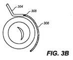
図3A〜図3Gは、心臓弁輪の領域にインプラントを送達し固定するための方法の詳細な図を提供しており、該方法においては、インプラントは、支持体と、支持体から延びている複数のアンカー部分とを含む。図3A〜図3Gにおいて、図2の僧帽弁(MV)は、下側の視点から見上げて概略的に描かれている。図3Aを参照すると、ガイドカテーテル(304)が、先に記載されたアクセスルート(またはその他任意の適切なアクセスルート)のいずれかを使用してSAG(302)に前進させられる。ガイドカテーテル(304)が、SAG(302)における所望の場所に配置された後、ガイドワイヤ(306)が、ガイドカテーテル(304)の管腔を通って前進させられる。ガイドワイヤ(306)は、ガイドカテーテル(304)の遠位端(308)を越えて前進させられるので、ガイドワイヤ(306)は、図3Bに示されているように、SAG(302)に沿ってガイドカテーテル(304)よりも遠くに延びる。 3A-3G provide a detailed view of a method for delivering and securing an implant in the region of a heart valve annulus, in which the implant extends from the support. A plurality of anchor portions. 3A-3G, the mitral valve (MV) of FIG. 2 is schematically depicted looking up from the lower viewpoint. Referring to FIG. 3A, the guide catheter (304) is advanced to the SAG (302) using any of the previously described access routes (or any other suitable access route). After the guide catheter (304) is placed at the desired location in the SAG (302), the guide wire (306) is advanced through the lumen of the guide catheter (304). As the guidewire (306) is advanced over the distal end (308) of the guide catheter (304), the guidewire (306) is along the SAG (302) as shown in FIG. 3B. Extending farther than the guide catheter (304).
ガイドワイヤ(306)が、SAGに配置された後、トンネルカテーテル(310)が、ガイドカテーテル(304)を通ってガイドワイヤ(306)上を前進させられ、このことが、図3Cに示されている。トンネルカテーテル(310)は、任意の適切なカテーテルであり得、一部の実施形態においては、トンネルカテーテルは、図3Cに例示されているトンネルカテーテルように、それの遠位端において事前成形または事前形成されることが、望ましい。そこで示されているように、トンネルカテーテルは、事前成形された遠位部分を有し、該事前成形された遠位部分は、湾曲を含む。このように、トンネルカテーテルは、僧帽弁の幾何形状にさらに容易に適合し得る。遠位の1つの湾曲が示されているが、ここで記載されたカテーテルまたはガイドワイヤのいずれもが、任意の数の適切な湾曲を含むように事前成形または事前形成され得ることもまた、理解されるべきである。当然、ここで記載されたガイドワイヤおよび/またはカテーテルはまた、操縦可能であり得る。 After the guide wire (306) is placed in the SAG, the tunnel catheter (310) is advanced over the guide wire (306) through the guide catheter (304), as shown in FIG. 3C. Yes. The tunnel catheter (310) may be any suitable catheter, and in some embodiments the tunnel catheter is pre-shaped or pre-formed at its distal end, such as the tunnel catheter illustrated in FIG. 3C. It is desirable to be formed. As shown therein, the tunnel catheter has a pre-shaped distal portion that includes a curvature. In this way, the tunnel catheter can be more easily adapted to the mitral valve geometry. Although one distal curve is shown, it is also understood that any of the catheters or guidewires described herein can be pre-shaped or preformed to include any number of suitable curves. It should be. Of course, the guidewires and / or catheters described herein may also be steerable.
トンネルカテーテル(310)は、SAGに配置された後、ガイドワイヤ(306)は、図3Dに示されているように、近位方向に引き込まれる。ガイドワイヤ(306)が、引き込まれた後、次に、送達シース(312)が、トンネルカテーテル(310)の管腔を通って前進させられ、そして、図3Eに示されているように、トンネルカテーテル(310)の遠位端(314)を通り過ぎて前進させられ得る。次に、図3Fに示されているように、インプラント(316)が、送達シース(312)からSAGに配備されると、送達シース(312)は、近位方向に引き込まれる。インプラント(316)は、支持体(318)と、フック(320)としてここで示された複数のアンカー部分とを含み、該複数のアンカー部分は、支持体から延びている。インプラントは、任意の適切な方式で送達シースから配備され得る。例えば、インプラントは、プッシュプル式ワイヤを使用して(例えば、ワイヤを遠位方向に押すこと、またはワイヤを近位方向に引くことによって)、プランジャを使用して、または任意のなんらかの適切な作動技術を使用して配備され得る。図3Fにおいて、送達シース(312)の近位方向の引き込みが、これらの作動技術のうちの1つ以上と共に作用して、インプラント(316)をSAGの中に配備する。しかしながら、ここで記載された方法の一部の変形例は、シースの引き込み技術とシースの作動技術との両方を使用してインプラントを配備することを含まないことがあり得る。例えば、ここで記載された方法の特定の変形例は、シースを引き込むこともなく、プッシャなどの1つ以上の作動デバイスを使用してインプラントを配備することだけを含み得る。 After the tunnel catheter (310) is placed in the SAG, the guide wire (306) is retracted in the proximal direction, as shown in FIG. 3D. After the guide wire (306) has been retracted, the delivery sheath (312) is then advanced through the lumen of the tunnel catheter (310) and, as shown in FIG. 3E, the tunnel It can be advanced past the distal end (314) of the catheter (310). Next, as shown in FIG. 3F, when the implant (316) is deployed from the delivery sheath (312) to the SAG, the delivery sheath (312) is retracted proximally. The implant (316) includes a support (318) and a plurality of anchor portions, shown here as hooks (320), that extend from the support. The implant can be deployed from the delivery sheath in any suitable manner. For example, the implant uses a push-pull wire (eg, by pushing the wire distally or pulling the wire proximally), using a plunger, or any suitable actuation Can be deployed using technology. In FIG. 3F, proximal withdrawal of the delivery sheath (312) works with one or more of these actuation techniques to deploy the implant (316) into the SAG. However, some variations of the methods described herein may not involve deploying the implant using both sheath retraction techniques and sheath actuation techniques. For example, certain variations of the methods described herein may include only deploying the implant using one or more actuation devices, such as pushers, without retracting the sheath.
図3Fに示されているように、インプラント(316)が、SAG、または輪の領域の組織に配備されたときに、フック(320)が、輪の領域の組織を係合し、それによりインプラント(316)を組織に固定する。インプラント上の複数のフックの存在が、インプラントが組織に比較的しっかりと固定されるという結果をもたらす。フックは、概して、輪組織に直接的に配備され得るか、またはSAGの付近において輪組織の少し下に配備され得ることが、理解されるべきである。 As shown in FIG. 3F, when the implant (316) is deployed in the tissue of the SAG, or annulus region, the hook (320) engages the tissue of the annulus region, thereby implanting the implant. Fix (316) to the tissue. The presence of multiple hooks on the implant results in the implant being relatively firmly fixed to the tissue. It should be understood that the hooks can generally be deployed directly on the annulus tissue or can be deployed slightly below the annulus tissue in the vicinity of the SAG.
図3Fに示されたインプラントは、フックを備えているが、ここで記載される方法およびデバイスと共に使用するアンカー部分は、任意の適切な構成または任意の適切な幾何形状を有し得る。同様に、アンカー部分は、任意の適切な材料で作られ、そして、任意の適切なサイズであり得る。さらに、アンカー部分は、1つの材料または2つ以上の材料で作られ得る。アンカー部分の材料の例は、超弾性材料または形状記憶材料を含み、例えば、ニッケルチタン合金およびバネステンレス鋼を含む。アンカー部分の適切な幾何形状は、Tタグ、リベット、ステープル、フック(例えば、C形状フックまたは半円形フック、他の形状の湾曲フック、直線フック、かかりつきフック)アンカー、かかり、およびクリップを含む。アンカー部分は、自己拡張し、そして、組織に自己固定するように構成され得るが、かかる方式で構成される必要はない。適切なインプラントの例示的な例は、例えば、米国特許出願第10/461,043号、同第10/656,797号、同第10/741,130号、同第10/776,682号、同第10/792,681号、同第10/901,019号、同第10/901,555号、同第10/901,554号、同第10/901,445号、同第10/901,444号、および同第11/202,474号にさらに詳細に記載されており、それらの全ては、それらの全体が参考として援用される。 Although the implant shown in FIG. 3F includes a hook, the anchor portion used with the methods and devices described herein may have any suitable configuration or any suitable geometry. Similarly, the anchor portion can be made of any suitable material and can be of any suitable size. Further, the anchor portion can be made of one material or more than one material. Examples of anchor portion materials include superelastic materials or shape memory materials, including, for example, nickel titanium alloys and spring stainless steel. Suitable geometries for anchor portions include T-tags, rivets, staples, hooks (eg, C-shaped or semi-circular hooks, other shaped curved hooks, straight hooks, barbed hooks) anchors, barbs, and clips. . The anchor portion may be configured to self-expand and self-fixate to the tissue, but need not be configured in such a manner. Illustrative examples of suitable implants include, for example, U.S. Patent Application Nos. 10 / 461,043, 10 / 656,797, 10 / 741,130, 10 / 776,682, No. 10 / 792,681, No. 10 / 9011,019, No. 10 / 901,555, No. 10 / 901,554, No. 10 / 901,445, No. 10/901 , 444, and 11 / 202,474, all of which are incorporated by reference in their entirety.
インプラント(316)の一部分が、SAGの領域に配備された後、送達シース(312)は、図3Gに示されているように、さらなる量を近位方向に引き込まれることにより、送達シース(312)からインプラント(316)のさらなる部分を配備する。インプラントのさらなる部分が、送達シース(312)から配備されると、インプラント上のさらなるフック(320)が、露出され、輪の領域の組織に固定される。最終的に、インプラント(316)の全体が、送達シース(312)からこの方式で配備され、輪の領域の組織にインプラント(316)を固定し得る。 After a portion of the implant (316) has been deployed in the region of the SAG, the delivery sheath (312) is retracted further in the proximal direction, as shown in FIG. ) To deploy further portions of the implant (316). As additional portions of the implant are deployed from the delivery sheath (312), additional hooks (320) on the implant are exposed and secured to the tissue in the region of the annulus. Eventually, the entire implant (316) may be deployed in this manner from the delivery sheath (312) to secure the implant (316) to the tissue in the region of the annulus.
ここで記載された方法の特定の変形例は、インプラント(316)の異なる部分の連続的な配備の間に支持体(318)に張力をかけること、またはそれを引張ることを含み得る。例えば、インプラント(316)の一部分が、輪の領域の組織に固定され得、次に、支持体(318)が、張力をかけられ得るか、または引張られ得、そして、インプラント(316)の別の部分が、輪の領域の組織に固定され得る。インプラント全体が、配備され、そして、それの様々な部分が、輪の領域の組織に固定されると、支持体が解放され得、それにより、それの元々の形態を取り戻し、そして、1つ以上のひだを組織に作り出す。上記の方法は、実質的に配備プロセスの全体にわたってインプラントの支持体に張力をかけ、そして、それを引張ることを含むが、ここで記載された方法の特定の変形例は、配備プロセスの選択された期間だけ、支持体に張力をかけるか、またはそれを引き伸ばし、そして、支持体を解放することを含み得る。 Certain variations of the methods described herein may include tensioning or tensioning the support (318) during successive deployment of different portions of the implant (316). For example, a portion of the implant (316) can be secured to the tissue in the region of the annulus, then the support (318) can be tensioned or tensioned, and the implant (316) can be separated. Can be secured to tissue in the area of the annulus. Once the entire implant has been deployed and various parts of it have been secured to the tissue in the area of the annulus, the support can be released, thereby regaining its original form and one or more Create folds in the organization. While the above method involves tensioning and pulling the support of the implant substantially throughout the deployment process, certain variations of the methods described herein may be selected for the deployment process. It may include tensioning or stretching the support for a period of time and releasing the support.
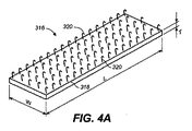
図4Aは、インプラント(316)をさらに詳細に示している。図4Aに示されているように、インプラント(316)は、支持体(318)と、フック(320)としてここで示された複数のアンカー部分とを含み、該複数のアンカー部分は、支持体(318)から延びている。支持体は、長さ(L)と、幅(W)と、厚さ(T)とを有する。支持体(318)のこれらの寸法のうちの1つ以上が、例えば、インプラント(316)が固定される部位の寸法、および/またはインプラント(316)を標的部位に配備するために使用される送達デバイスの寸法に基づいて選択され得る。一部の変化形において、長さ(L)は、約30ミリメートル〜約70ミリメートルであり得、幅(W)は、約2ミリメートル〜約3ミリメートルであり得、および/または厚さ(T)は、約0.5ミリメートル〜約1ミリメートルであり得る。 FIG. 4A shows the implant (316) in more detail. As shown in FIG. 4A, the implant (316) includes a support (318) and a plurality of anchor portions shown here as hooks (320), the plurality of anchor portions comprising the support (318). The support has a length (L), a width (W), and a thickness (T). One or more of these dimensions of the support (318) may include, for example, the dimensions of the site to which the implant (316) is secured and / or the delivery used to deploy the implant (316) to the target site. It can be selected based on the dimensions of the device. In some variations, the length (L) can be about 30 millimeters to about 70 millimeters, the width (W) can be about 2 millimeters to about 3 millimeters, and / or the thickness (T). Can be between about 0.5 millimeters and about 1 millimeter.
支持体(318)は、任意の適切な生体適合性材料から作られ得る。例えば、支持体は、1つ以上のポリマーから作られ得る。ポリマーの例は、ポリエーテル−ブロック共ポリアミドポリマー、コポリエステルエラストマー、熱可塑性ポリエステルエラストマー、熱可塑性ポリウレタンエラストマー、ポリオレフィン(例えば、ポリエチレン、ポリプロピレン)、ポリウレタン、ポリスチレン、ポリカーボネート、ポリエステル、ポリアミド、ポリエーテルエーテルケトン(PEEK)、ポリテトラフルオロエチレン、または延伸ポリテトラフルオロエチレン、およびシリコーンを含む。支持体(318)に適切であり得る材料の他の例は、金属、金属合金、および形状記憶材料(例えば、形状記憶ポリマー、ニッケルチタン合金、またはバネステンレス鋼)を含む。一部の変形例において、支持体(318)は、1つ以上の生物分解性材料を含み得る。さらに詳細に以下で記載されるように、組織固定プロセスは、一時的に、インプラントの支持体に張力をかけるか、またはそれを引張ることを含み得る。支持体は、この一時的に張力をかけること、またはこの一時的に引張ることに適合する1つ以上の材料、例えば、1つ以上の形状記憶材料で形成され得る。 The support (318) can be made from any suitable biocompatible material. For example, the support can be made from one or more polymers. Examples of polymers are polyether-block copolyamide polymers, copolyester elastomers, thermoplastic polyester elastomers, thermoplastic polyurethane elastomers, polyolefins (eg polyethylene, polypropylene), polyurethanes, polystyrenes, polycarbonates, polyesters, polyamides, polyetheretherketones. (PEEK), polytetrafluoroethylene, or expanded polytetrafluoroethylene, and silicone. Other examples of materials that may be suitable for the support (318) include metals, metal alloys, and shape memory materials (eg, shape memory polymers, nickel titanium alloys, or spring stainless steel). In some variations, the support (318) may include one or more biodegradable materials. As described in more detail below, the tissue fixation process may involve temporarily tensioning or pulling the support of the implant. The support may be formed of one or more materials, such as one or more shape memory materials, that are temporarily tensioned or compatible with this temporary tensioning.
同様に、フック(320)としてここで示されたアンカー部分は、1つの材料または2つ以上の材料で作られ得る。アンカー部分に対する適切な材料の例は、金属、金属合金、ポリマー、および超弾性材料または形状記憶材料を含み、例えば、ニッケルチタン合金およびバネステンレス鋼を含む。特定の変形例において、フック(320)は、可撓性をフック(320)に付与するために選択された1つ以上の材料で作られ得る。この可撓性が、例えば、フック(320)が曲がって、送達シース(312)に嵌合することを可能にし得る。 Similarly, the anchor portion, shown here as a hook (320), can be made of one material or more than one material. Examples of suitable materials for the anchor portion include metals, metal alloys, polymers, and superelastic or shape memory materials, including, for example, nickel titanium alloys and spring stainless steel. In certain variations, the hook (320) may be made of one or more materials selected to impart flexibility to the hook (320). This flexibility may allow, for example, the hook (320) to bend and fit into the delivery sheath (312).
フック(320)は、支持体(318)と同じ材料で作られ得るか、または支持体(318)とは異なる1つ以上の材料で作られ得る。例として、一部の変形例において、フック(320)は、ニッケルチタン合金で作られ得るが、支持体(318)は、ポリマーで作られ得る。特定の変形例において、フック(320)は、支持体(318)とは別個に形成され、そして、後で、支持体(318)に取り付けられ得る。他の変形例において、フック(320)は、支持体(318)と一体で形成され得る。さらに、インプラント(316)の一部の変形例は、支持体(318)と一体で形成されたフック(320)と、支持体(318)に取り付けられたフック(320)との両方を含み得る。 The hook (320) can be made of the same material as the support (318) or can be made of one or more materials different from the support (318). As an example, in some variations, the hook (320) can be made of a nickel titanium alloy, while the support (318) can be made of a polymer. In certain variations, the hook (320) may be formed separately from the support (318) and later attached to the support (318). In other variations, the hook (320) may be integrally formed with the support (318). Further, some variations of the implant (316) may include both a hook (320) integrally formed with the support (318) and a hook (320) attached to the support (318). .
インプラント(316)などのインプラントは、多数の適切な方法を使用して形成され得る。インプラントのフックのうちの1つ以上が、支持体に取り付けられる変形例においては、支持体にフックを部分的に埋め込むことによって、支持体にフックを接着剤結合することによって、および/または支持体にフックを溶接することによって、フックは、支持体に取り付けられ得る。インプラントのフックのうちの1つ以上が、支持体と一体で形成される変形例において、フックは、支持体材料から鋳造され得るか、または支持体材料の中に打ち抜かれ得るか、もしくは切り込まれ得るか、あるいは支持体と、一体で形成されたフックとが、押出プロセスを使用して形成され得る。 An implant, such as implant (316), can be formed using a number of suitable methods. In variations in which one or more of the implant hooks are attached to the support, by partially embedding the hook in the support, by adhesively bonding the hook to the support, and / or the support. By welding the hook to the hook, the hook can be attached to the support. In variations in which one or more of the implant hooks are formed integrally with the support, the hook can be cast from the support material or can be stamped or cut into the support material. It can be rare, or the support and the integrally formed hook can be formed using an extrusion process.
図4Bは、フック(312)が輪(AN)の領域の組織に固定されたインプラント(316)を示す。ここで記載される変形例において、フック(320)は、湾曲した頭部(322)を有し、該湾曲した頭部(322)は全て、同じ方向に向いている。方向のこの統一性が、例えば、インプラント(316)が組織から外れる可能性の減少をもたらす。さらに、フックが組織に固定されると、支持体は、フックの頭部が向いている方向に引かれ得る。これがまた、インプラント(316)が組織から外れる可能性の減少をもたらし得る。しかしながら、インプラントの一部の変形例は、異なる方向に向いている頭部を有するフックを含み得ることが、理解されるべきである。異なるフックは、例えば、組織の異なる領域を係合するために使用され得る。異なる方向に向いている頭部を有するフックは、さらに詳細に以下で記載される。 FIG. 4B shows the implant (316) with the hook (312) secured to the tissue in the region of the annulus (AN). In the variation described here, the hook (320) has a curved head (322), all of which are oriented in the same direction. This unity of orientation results, for example, in reducing the likelihood that the implant (316) will be dislodged from the tissue. Further, once the hook is secured to the tissue, the support can be pulled in the direction in which the head of the hook is facing. This may also result in a reduced likelihood that the implant (316) will become detached from the tissue. However, it should be understood that some variations of the implant may include hooks having heads that are oriented in different directions. Different hooks can be used, for example, to engage different regions of tissue. Hooks having heads facing in different directions are described in more detail below.
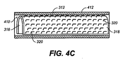
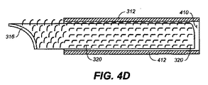
図4Cおよび図4Dは、送達シース(312)から送達されるインプラント(316)を示す。図4Cに示されているように、送達シース(312)は、管腔(410)を含み、該管腔(410)の中に、インプラント(316)は、部分的に丸められた形態で配置される。図4Dに示されているように、送達シース(312)は、近位方向に引き込まれ、そして、プッシャ(図示せず)などのアクチュエータが、送達シース(312)からインプラント(316)を配備するために使用される。インプラントが、配備されると、インプラントは、広がり、そして、平らになり始める。さらに、フックが送達シース(312)の制約から抜け出ると、シース(312)の側壁(412)によって圧縮されたフック(320)は、フックの形状を回復する。 4C and 4D show the implant (316) delivered from the delivery sheath (312). As shown in FIG. 4C, the delivery sheath (312) includes a lumen (410) in which the implant (316) is disposed in a partially rolled configuration. Is done. As shown in FIG. 4D, delivery sheath (312) is retracted proximally and an actuator, such as a pusher (not shown), deploys implant (316) from delivery sheath (312). Used for. As the implant is deployed, the implant begins to expand and flatten. In addition, when the hook comes out of the constraints of the delivery sheath (312), the hook (320) compressed by the side wall (412) of the sheath (312) restores the shape of the hook.
上記の方法は、送達シースだけを使用してインプラントを組織に送達することを含むが、他の方法は、1つ以上の追加の送達デバイスを使用することを含む。例えば、一部の変形例において、内側部材と外側シースとを含む送達カテーテルが、インプラントを標的部位に送達するために使用され得る。インプラントは、内側部材と外側シースとの間の空間の中に配置され得、そして、送達カテーテルが、標的組織に前進させられ得る。その後、シースは、引き込まれ得、そして、インプラントが、送達シースから配備され、そして、組織に固定され得る。例として、図23Aは、内側部材(2302)と、内側部材(2302)に配置された拡張可能部材(2304)と、内側部材(2302)を囲む外側シース(2306)とを含む送達カテーテル(2300)を示す。示されているように、拡張可能部材(2304)は、バルーンであるが、他の適切な拡張可能部材が、使用され得る。内側部材と、送達カテーテルの外側シースとは、それらの間に管腔(2308)を画定する。インプラント(2310)は、拡張可能部材(2304)上に配置されるので、インプラントは、管腔(2308)の中に配置される。図23Bに示されているように、シース(2306)が近位方向に引き抜かれ、そして、拡張可能部材(2304)が、拡張されると、インプラントは、配備される。このようにして、インプラント(2310)は、広がり、そして、組織(2316)に固定される。ここで記述される他のインプラントに関しては、インプラント(2310)は、支持体(2312)と、支持体から延びているアンカー部分(2314)とを含む。インプラント(2310)が配備されると、アンカー部分(2314)は、組織(2316)に固定される。 While the above method involves using only a delivery sheath to deliver the implant to the tissue, other methods include using one or more additional delivery devices. For example, in some variations, a delivery catheter that includes an inner member and an outer sheath can be used to deliver the implant to the target site. The implant can be placed in the space between the inner member and the outer sheath, and the delivery catheter can be advanced to the target tissue. Thereafter, the sheath can be retracted and the implant can be deployed from the delivery sheath and secured to the tissue. By way of example, FIG. 23A shows a delivery catheter (2300) that includes an inner member (2302), an expandable member (2304) disposed on the inner member (2302), and an outer sheath (2306) surrounding the inner member (2302). ). As shown, the expandable member (2304) is a balloon, but other suitable expandable members may be used. The inner member and the outer sheath of the delivery catheter define a lumen (2308) therebetween. Since the implant (2310) is disposed on the expandable member (2304), the implant is disposed within the lumen (2308). As shown in FIG. 23B, when the sheath (2306) is withdrawn proximally and the expandable member (2304) is expanded, the implant is deployed. In this way, the implant (2310) expands and is secured to the tissue (2316). With respect to the other implants described herein, the implant (2310) includes a support (2312) and an anchor portion (2314) extending from the support. When the implant (2310) is deployed, the anchor portion (2314) is secured to the tissue (2316).
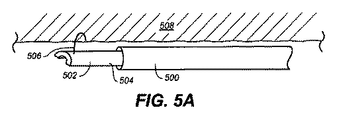
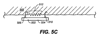
上に記載されているように、一部の方法は、インプラントの一部分を組織に固定することと、インプラントの支持体を引張ることと、インプラントの別の部分を組織に固定することと、次に、インプラントが1つ以上のひだを組織に形成することを可能にするためにインプラントを解放することとを含み得る。図5A〜図5Cは、かかる方法の一変形例をさらに詳細に描いている。図5Aは、送達シース(500)を示し、該送達シース(500)は、組織(508)の領域にインプラント(502)を送達するために使用される。インプラントは、上記の配備技術の任意のものを使用して送達シースから配備され得る。例えば、インプラントは、シースを近位方向に引き込み、そして、プッシャを用いてシースからインプラントを押すことによってシースから配備され得る。インプラント(502)は、支持体(504)を含み、該支持体(504)からフック(506)が延びている。フック(506)が、組織(508)に固定され、それにより、インプラント(502)を組織に固定する。図5Aに示されているように、インプラントが、送達シース(500)を出ると、インプラント(502)は、最初、湾曲した構成である。しかしながら、インプラント(502)が、送達シース(500)から配備され続けると、インプラント(502)は、湾曲した構成を失い、図5Bに示されているように、より真っ直ぐな形状をとる。フック(506)が、組織(508)に固定した後、送達シース(500)は、さらに引き抜かれ、それにより、標的部位への配備のためにインプラント(502)のさらなる長さを露出させる。インプラント(502)が、送達シース(500)から配備され続けると、支持体(504)は、矢印(A1)の方向に引張られ、そして、インプラント(502)の第2のフック(510)が、組織(508)の異なる領域に留められる。ここで図5Cを参照すると、インプラント(502)が、送達シース(500)から完全に配備されると、支持体(504)が、解放される。支持体(504)の解放は、支持体(504)に元々の形態を回復させ、フック(506)とフック(510)との間の組織(508)の領域(512)にひだの形成をもたらす。この方法は、(例えば、心臓組織の様々な領域に複数のインプラントを送達するために)繰り返されることも、繰り返されないこともあり得、そして、例えば、輪組織の形を変えることによって僧帽弁輪を修復するために使用され得る。 As described above, some methods include securing a portion of the implant to the tissue, pulling the support of the implant, securing another portion of the implant to the tissue, and Releasing the implant to allow the implant to form one or more pleats in the tissue. 5A-5C depict one variation of such a method in greater detail. FIG. 5A shows a delivery sheath (500) that is used to deliver an implant (502) to a region of tissue (508). The implant can be deployed from the delivery sheath using any of the deployment techniques described above. For example, the implant can be deployed from the sheath by retracting the sheath proximally and pushing the implant from the sheath with a pusher. The implant (502) includes a support (504) from which a hook (506) extends. A hook (506) is secured to the tissue (508), thereby securing the implant (502) to the tissue. As shown in FIG. 5A, as the implant exits the delivery sheath (500), the implant (502) is initially in a curved configuration. However, as the implant (502) continues to be deployed from the delivery sheath (500), the implant (502) loses the curved configuration and assumes a straighter shape, as shown in FIG. 5B. After the hook (506) is secured to the tissue (508), the delivery sheath (500) is further withdrawn, thereby exposing an additional length of the implant (502) for deployment to the target site. As the implant (502) continues to be deployed from the delivery sheath (500), the support (504) is pulled in the direction of the arrow (A1) and the second hook (510) of the implant (502) is Pinned in different areas of tissue (508). Referring now to FIG. 5C, when the implant (502) is fully deployed from the delivery sheath (500), the support (504) is released. Release of the support (504) restores the original form to the support (504) and results in the formation of pleats in the region (512) of the tissue (508) between the hook (506) and the hook (510). . This method may or may not be repeated (eg, to deliver multiple implants to various regions of the heart tissue) and, for example, by changing the shape of the ring tissue Can be used to repair the annulus.
ここで記載されるインプラントは、任意の適切な形状のアンカー部分を有し得る。例えば、図6および図7は、異なる構成のアンカー部分を有するインプラントを示し、ループ状アンカーとして示されている。さらに詳細には、図6は、支持体(602)と、支持体(602)の一方の側(606)において比較的均一に間隔を空けられたアンカー(604)とを有するインプラント(600)を示す。図7において、インプラント(700)が示され、該インプラント(700)は、支持体(702)と、支持体の一方の側(711)の角(706)、(708)、(710)、および(712)のそれぞれから延びているアンカー(704)とを有する。 The implants described herein may have any suitable shaped anchor portion. For example, FIGS. 6 and 7 show implants with differently configured anchor portions and are shown as looped anchors. More particularly, FIG. 6 shows an implant (600) having a support (602) and a relatively evenly spaced anchor (604) on one side (606) of the support (602). Show. In FIG. 7, an implant (700) is shown, the implant (700) comprising a support (702) and corners (706), (708), (710) on one side (711) of the support, and Anchors (704) extending from each of (712).
インプラントは、比較的多くの数のアンカー部分を含み得るか、または比較的少ない数のアンカー部分を含み得る。例えば、図8に示されたインプラント(800)は、支持体(802)と、支持体の一方の側(808)の対向する端から延びている2つのアンカー部分(804)および(806)だけを含む。例えば、インプラント(800)のようなインプラントは、(例えば、組織に1つ以上のひだを形成することによって)一時的に組織の形を変えることに有用であり得る。一時的に心臓組織の形を変えることが、実際の修復処置の間に達成される組織のひだの適切な量を決定するために利用され得る。インプラントにおける比較的少ない数のアンカー部分は、一時的に組織の形を変えることが、もはや必要なくなると、組織からのインプラントの容易な取り除きまたは分離を可能にし得る。 The implant can include a relatively large number of anchor portions or a relatively small number of anchor portions. For example, the implant (800) shown in FIG. 8 includes only a support (802) and two anchor portions (804) and (806) extending from opposite ends of one side (808) of the support. including. For example, an implant such as implant (800) may be useful for temporarily changing the shape of the tissue (eg, by forming one or more pleats in the tissue). Temporarily changing the shape of the heart tissue can be utilized to determine the appropriate amount of tissue folds to be achieved during the actual repair procedure. A relatively small number of anchor portions in the implant may allow easy removal or separation of the implant from the tissue when it is no longer necessary to temporarily change the shape of the tissue.
インプラントは、異なるパターンのアンカー部分を含み得るか、または標的組織の構造に対応するようにインプラントに配置されたアンカー部分を含み得る。例として、図9は、支持体(902)と、支持体の一方の側(906)から延びている複数のアンカー(904)とを含むインプラント(900)を示す。アンカー(904)は、「X」パターンで配置されているが、他のパターンもまた、使用され得る。例えば、インプラントは、僧帽弁輪の湾曲に対応するように湾曲パターンを形成するアンカー部分を含み得る。さらに、比較的対称的な配置のアンカー部分を有するインプラントが、示されているが、インプラントの一部の変形例は、非対称的に配置されたアンカー部分を含み得る。さらに、インプラントの一部の部分は、対称的に配置されたアンカー部分を含み得るが、インプラントの他の部分は、非対称的に配置されたアンカー部分を含む。 The implant may include different patterns of anchor portions or may include anchor portions disposed on the implant to correspond to the structure of the target tissue. As an example, FIG. 9 shows an implant (900) that includes a support (902) and a plurality of anchors (904) extending from one side (906) of the support. Anchors (904) are arranged in an “X” pattern, but other patterns may also be used. For example, the implant may include an anchor portion that forms a curved pattern to accommodate the curvature of the mitral annulus. Further, although an implant having a relatively symmetric arrangement of anchor portions is shown, some variations of implants may include asymmetrically arranged anchor portions. Further, some portions of the implant may include symmetrically disposed anchor portions, while other portions of the implant include asymmetrically disposed anchor portions.
支持体の1つの表面から延びているアンカー部分を有するインプラントが、示されているが、インプラントの一部の変形例は、支持体の2つ以上の表面から延びているアンカー部分を含み得る。例えば、図10は、支持体(1002)と、支持体の、背中合わせの表面(1006)および(1008)から延びているアンカー(1004)とを含むインプラント(1000)を示す。インプラント(1000)は、例えば、組織修復処置において使用され得、該組織修復処置においては、インプラントが、組織の中の裂け目(例えば、僧帽弁尖と心室壁との間の空間)に固定される。インプラントの複数の表面から延びているアンカーの存在が、インプラントが周囲の組織により良く固定されることを助け得る。一部の変形例において、インプラントの表面全体が、実質的に、アンカー部分で覆われ得る。 Although an implant having an anchor portion extending from one surface of the support is shown, some variations of the implant may include anchor portions extending from more than one surface of the support. For example, FIG. 10 shows an implant (1000) that includes a support (1002) and anchors (1004) extending from the back-to-back surfaces (1006) and (1008) of the support. The implant (1000) can be used, for example, in a tissue repair procedure, in which the implant is secured to a tear in the tissue (eg, the space between the mitral valve leaflet and the ventricular wall). The The presence of anchors extending from multiple surfaces of the implant can help the implant to be better anchored to the surrounding tissue. In some variations, the entire surface of the implant can be substantially covered with an anchor portion.
インプラントはまた、異なる形状を有する支持体を含み得る。例として、図11は、円形の支持体(1102)と、支持体から延びているアンカー(1104)とを含むインプラント(1100)を示す。円形の支持体が、示されているが、支持体は、多数の様々な形状の任意のもの、例えば、楕円形、長方形、正方形、三角形、六角形などを有し得るか、または不規則な形状を有し得る。例えば、図12は、第1の部分(1204)と第2の部分(1206)とを有する支持体(1202)を含むインプラント(1200)を示し、該インプラント(1200)においては、第1の部分と第2の部分とは、第3の部分(1208)によって接合されている。この変形例において、アンカー(1210)は、第1の部分と第2の部分とからのみ延びている。しかしながら、複数の部分を有する支持体を含むインプラントは、それらの部分の全て、それらの部分の一部、または1つの部分だけから延びているアンカー部分を有し得る。第1の部分(1204)と、第2の部分(1206)と、第3の部分(1208)とは全て、同じ材料で形成され得るか、または異なる材料から形成され得る。一部の変形例において、支持体の第3の部分は、張力をかけられるか、または引き伸ばされ、そして、支持体が張力を受けなくなると、元々の形状に戻ることができる材料から形成され得る。上記のように、引伸しと解放とのこのプロセスは、組織修復プロセスの間、組織の形を変えるために使用され得る。 The implant can also include supports having different shapes. As an example, FIG. 11 shows an implant (1100) that includes a circular support (1102) and an anchor (1104) extending from the support. Although a circular support is shown, the support may have any of a number of different shapes, for example, oval, rectangular, square, triangular, hexagonal, etc., or irregular It can have a shape. For example, FIG. 12 shows an implant (1200) that includes a support (1202) having a first portion (1204) and a second portion (1206), in which the first portion And the second part are joined by a third part (1208). In this variation, the anchor (1210) extends only from the first portion and the second portion. However, an implant that includes a support having multiple portions may have an anchor portion that extends from all of the portions, a portion of the portions, or only one portion. The first portion (1204), the second portion (1206), and the third portion (1208) can all be formed from the same material or from different materials. In some variations, the third portion of the support can be formed from a material that can be tensioned or stretched and return to its original shape when the support is no longer under tension. . As described above, this process of stretching and releasing can be used to change the shape of the tissue during the tissue repair process.
例えば、図13は、2つの異なる部分(1304)および(1306)を有する支持体(1302)を含むインプラント(1300)を示す。異なる支持体部分は、バネ(1308)によって互いに取り付けられる。この変形例において、アンカー部分(1310)および(1312)は、支持体の両方の部分から延びているが、部分(1304)から延びているアンカー部分(1310)のフックは、一方の方向に向いているが、部分(1306)から延びているアンカー部分(1312)のフックは、反対方向に向いている。インプラント(1000)を使用する一部の方法は、組織の1つの領域にアンカー部分(1310)を留めることと、バネ(1308)を引張ることと、次に、組織の別の領域にアンカー部分(1312)を留めることとを含み得る。インプラントが、解放されると、バネは、元々の位置を回復し得、それにより、支持体(1302)の異なる部分を互いに近づけさせ、そして、それらの間の組織に1つ以上のひだを形成させ得る。図13は、反対方向に向いているフックを有するアンカー部分を示すが、インプラントは、互いに対して異なる多数の配向のいずれかを有するフックを有するアンカー部分を含み得ることが、理解されるべきである。 For example, FIG. 13 shows an implant (1300) that includes a support (1302) having two different portions (1304) and (1306). The different support parts are attached to each other by a spring (1308). In this variation, anchor portions (1310) and (1312) extend from both portions of the support, but the hook of anchor portion (1310) extending from portion (1304) faces in one direction. However, the hook of the anchor portion (1312) extending from the portion (1306) points in the opposite direction. Some methods of using the implant (1000) include securing the anchor portion (1310) to one region of tissue, pulling the spring (1308), and then anchoring portions ( 1312). When the implant is released, the spring may restore its original position, thereby bringing different parts of the support (1302) closer together and forming one or more pleats in the tissue between them Can be. Although FIG. 13 shows an anchor portion having hooks oriented in opposite directions, it should be understood that the implant may include anchor portions having hooks having any of a number of different orientations relative to each other. is there.
特定の形状のアンカー部分が示されているが、ここで記載されたインプラントは、上に記載されたように、任意の数の異なる形状、任意の数の異なるサイズ、または任意の数の異なる構成を有するアンカー部分を有し得ることが、理解されるべきである。例えば、インプラントは、全て同じ形状を有するアンカー部分、全て異なる形状を有するアンカー部分、または2つの何らかの組み合わせを含み得る。適切なアンカー部分の例は、図14〜図17に示されている。 Although particular shaped anchor portions are shown, the implants described herein may be any number of different shapes, any number of different sizes, or any number of different configurations, as described above. It should be understood that an anchor portion having For example, an implant may include anchor portions that all have the same shape, anchor portions that all have different shapes, or some combination of the two. Examples of suitable anchor portions are shown in FIGS.
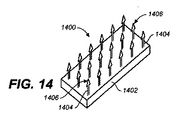
図14は、支持体(1402)と、かかりつきアンカー部分(1404)とを備えているインプラント(1400)を示し、該かかりつきアンカー部分(1404)は、支持体から延びている。かかりつきアンカー部分(1404)の遠位端(1406)は、矢印構成を有する。この矢印構成は、かかりつきアンカー部分が組織に固定される能力を向上させ得、そして、かかりつきアンカー部分が組織から外れる可能性を減少させ得る。 FIG. 14 shows an implant (1400) comprising a support (1402) and a barbed anchor portion (1404), the barge anchor portion (1404) extending from the support. The distal end (1406) of the barbed anchor portion (1404) has an arrow configuration. This arrow configuration can improve the ability of the barbed anchor portion to be secured to the tissue and can reduce the likelihood that the barbed anchor portion will be dislodged from the tissue.
図15は、インプラント(1500)を示し、該インプラント(1500)は、支持体(1502)と、かかりつきアンカー部分(1504)とを備え、該かかりつきアンカー部分(1504)は、支持体から延びている。ここで示されたかかりつきアンカー部分(1504)は、銛構成を有する遠位端(1506)を含む。かかりつきアンカー部分(1504)もまた、組織から外れる可能性を減少させ得る。 FIG. 15 shows an implant (1500) that includes a support (1502) and a barbed anchor portion (1504), the barge anchor portion (1504) extending from the support. ing. The barbed anchor portion (1504) shown here includes a distal end (1506) having a heel configuration. Bare anchor portion (1504) may also reduce the likelihood of detachment from tissue.
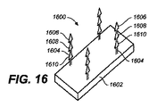
かかりつきアンカー部分は、1つのかかり、または複数のかかりを含み得る。例えば、図16は、支持体(1602)と、かかりつきアンカー部分(1604)とを有するインプラント(1600)を示し、該かかりつきアンカー部分(1604)は、支持体(1602)から延びている。かかりつきアンカー部分(1604)はそれぞれ、3つのかかり(1606)、(1608)、および(1610)を有する。アンカー部分のかかりの数が、増加すると、アンカー部分が組織から外れる可能性が、減少し得る。同じ数のかかりを有するかかりつきアンカー部分を含むインプラントが、記載されているが、インプラントの一部の変形例は、異なる数のかかりを有するアンカー部分を含み得る。さらに、インプラントの特定の変形例は、異なる構成を有する遠位端を有するアンカー部分を含み得る。 The barge anchor portion may include one barb or multiple barbs. For example, FIG. 16 shows an implant (1600) having a support (1602) and a barge anchor portion (1604), which barge anchor portion (1604) extends from the support (1602). Each barbed anchor portion (1604) has three barbs (1606), (1608), and (1610). As the number of anchor portions increases, the likelihood that the anchor portions will dislodge from the tissue may decrease. Although implants have been described that include barbed anchor portions having the same number of barbs, some variations of implants may include anchor portions having different numbers of barbs. Further, certain variations of the implant may include an anchor portion having a distal end with a different configuration.
図17は、支持体(1702)と、傘形状の複数のアンカー部分(1704)とを含むインプラント(1700)を示し、該傘形状の複数のアンカー部分(1704)は、支持体から延びている。傘形状のアンカー部分はそれぞれ、柄(1706)と、柄の遠位端(1710)から延びている複数の支柱(1708)と、支柱を覆う膜(1712)とを含む。支柱は、縮小された構成から再構成可能であり得、該縮小された構成においては、支柱は、柄(1706)に向かって圧縮されている。拡張の際、支柱は、図17に示された傘形状のプロフィールを回復する。このように、アンカー部分(1704)は、縮小した構成で組織の中に配備され得、そして、次に、組織に入った後、拡張させられ得る。図17の傘形状のアンカー部分は、膜(1712)を含むが、一部の変形例においては、アンカー部分は、柄と支柱とを含むが、膜を含まないことがあり得る。 FIG. 17 shows an implant (1700) comprising a support (1702) and a plurality of umbrella-shaped anchor portions (1704), the plurality of anchor-shaped anchor portions (1704) extending from the support. . Each umbrella-shaped anchor portion includes a handle (1706), a plurality of struts (1708) extending from the distal end (1710) of the handle, and a membrane (1712) covering the struts. The struts can be reconfigurable from a reduced configuration, in which the struts are compressed toward the handle (1706). Upon expansion, the strut recovers the umbrella-shaped profile shown in FIG. In this way, the anchor portion (1704) can be deployed into the tissue in a contracted configuration and then expanded after entering the tissue. The umbrella-shaped anchor portion of FIG. 17 includes a membrane (1712), but in some variations, the anchor portion includes a handle and struts, but may not include a membrane.
上記のように、インプラントはまた、異なる方向に向いているアンカー部分を含み得、および/または複数の異なるタイプのアンカー部分を含み得る。例えば、図18は、支持体(1802)と、かかりつきアンカー部分(1804)および(1806)とを含むインプラント(1800)を示し、該かかりつきアンカー部分(1804)および(1806)は、支持体から延びている。かかりつきアンカー部分(1804)は、かかりつきアンカー部分(1806)とは異なる方向に向いている。図19は、支持体(1902)と、アンカー(1904)およびアンカー(1906)とを含むインプラント(1900)を示し、該アンカー(1904)および該アンカー(1906)は、支持体(1902)から延びている。示されたインプラント(1900)は、2つの異なるタイプのアンカー部分だけを含むが、インプラントは、任意の数の異なるタイプのアンカー部分を備え得る。例えば、インプラントは、3、4、5、または10個の異なるタイプのアンカー部分を有し得る。 As noted above, the implant may also include anchor portions that are oriented in different directions and / or may include a plurality of different types of anchor portions. For example, FIG. 18 shows an implant (1800) that includes a support (1802) and barbed anchor portions (1804) and (1806), the barge anchor portions (1804) and (1806) It extends from. The barbed anchor portion (1804) is oriented in a different direction from the barbed anchor portion (1806). FIG. 19 shows an implant (1900) that includes a support (1902) and an anchor (1904) and anchor (1906), which anchor (1904) and the anchor (1906) extend from the support (1902). ing. Although the illustrated implant (1900) includes only two different types of anchor portions, the implant may comprise any number of different types of anchor portions. For example, the implant may have 3, 4, 5, or 10 different types of anchor portions.
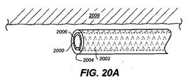
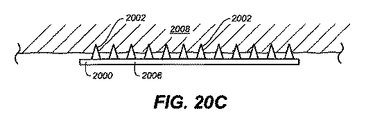
インプラントの一部の変形例において、アンカー部分は、こぶ状の突起またはスパイク形状の突起の形態であり得る。例えば、図20A〜図20Cは、標的組織(2008)へのスパイク形状のアンカー部分(2002)を有するインプラント(2000)の送達を例示する。図20Aに示されているように、インプラント(2000)は、標的組織部位に前進させるために送達シース(2004)の中で部分的に丸められている。インプラント(2000)は、支持体(2006)を含み、該支持体(2006)から、スパイク形状のアンカー部分(2002)が延びている。インプラント(2000)が、(例えば、送達シースを近位方向に引き抜き、そして、プッシャを用いて送達シースからインプラントを押すことによって)送達シース(2004)から配備されると、インプラント(2000)は、広がる。結果として、スパイク形状のアンカー部分(2002)は、図20Bに示されているように、標的組織に向く。図20Cに示されているように、インプラント(2000)が、完全に配備された後、スパイク形状のアンカー部分(2002)は、組織(2008)に固定される。 In some variations of the implant, the anchor portion can be in the form of a hump-like protrusion or a spike-shaped protrusion. For example, FIGS. 20A-20C illustrate delivery of an implant (2000) having a spike-shaped anchor portion (2002) to a target tissue (2008). As shown in FIG. 20A, the implant (2000) is partially rounded in the delivery sheath (2004) for advancement to a target tissue site. The implant (2000) includes a support (2006) from which a spike-shaped anchor portion (2002) extends. When the implant (2000) is deployed from the delivery sheath (2004) (eg, by pulling the delivery sheath proximally and pushing the implant from the delivery sheath with a pusher), the implant (2000) is spread. As a result, the spike-shaped anchor portion (2002) faces the target tissue, as shown in FIG. 20B. As shown in FIG. 20C, after the implant (2000) is fully deployed, the spike-shaped anchor portion (2002) is secured to the tissue (2008).
支持体もまた、任意の適切な形状のものであり得、そして、必ずしも、上に記述された支持体のように画定可能な側面を有していないことがあり得る。例として、図21Aおよび図21Bは、標的組織へのインプラントの送達を例示し、ここでは、インプラントは、概ね円筒形の支持体を含む。 The support can also be of any suitable shape, and may not necessarily have definable sides like the support described above. As an example, FIGS. 21A and 21B illustrate the delivery of an implant to a target tissue, where the implant includes a generally cylindrical support.
図21Aは、送達シース(2104)から標的組織(2102)へのインプラント(2100)の送達を示し、ここでは、インプラント(2100)は、概ね円筒形の支持体(2106)を備え、該概ね円筒形の支持体(2106)から、自己固定アンカー(2108)が、延びている。インプラント(2100)が、送達シース(2104)から送達されると、自己固定アンカー(2108)は、自己拡張し、そして、組織(2102)に自己固定する。図21Cは、送達シース(2104)の管腔(2110)の中のインプラント(2100)を示す。図21Cに示されているように、アンカー(2108)は、実質的に、送達シースの側壁(2112)によって、概ね円筒形の支持体(2106)に扁平にされている。しかしながら、インプラント(2100)が送達シースから配備されると、アンカーは、自己拡張し、そして、それらの元々の形状を回復し、それらの端が、互いに向かって内側に湾曲してループを形成する。アンカーが自己拡張すると、それらはまた、組織に自己固定する。 FIG. 21A shows delivery of the implant (2100) from the delivery sheath (2104) to the target tissue (2102), where the implant (2100) comprises a generally cylindrical support (2106) that is generally cylindrical. Extending from the shaped support (2106) is a self-fixating anchor (2108). As the implant (2100) is delivered from the delivery sheath (2104), the self-fixating anchor (2108) self-expands and self-fixes to the tissue (2102). FIG. 21C shows the implant (2100) in the lumen (2110) of the delivery sheath (2104). As shown in FIG. 21C, the anchor (2108) is flattened to a generally cylindrical support (2106) substantially by the sidewall (2112) of the delivery sheath. However, when the implant (2100) is deployed from the delivery sheath, the anchors will self-expand and restore their original shape, and their ends will curve inward toward each other to form a loop. . As anchors self-expand, they also self-fix to the tissue.
インプラント(2100)の概ね円筒形の支持体(2106)は、管腔を有していないが、インプラントの一部の変形例は、1つ以上の管腔を有する概ね円筒形の支持体を備え得る。管腔は、例えば、1つ以上の治療剤を標的組織に送達するために使用され得る。一部の変形例において、管腔を含む概ね円筒形の支持体は、1つ以上の形状記憶材料で形成され得る。インプラントが、(例えば、シースを引き抜くことによって)心臓組織に配備されると、概ね円筒形の支持体が、拡張する。この拡張が、概ね円筒形の支持体から延びているアンカー部分を心臓組織に接触させ、そして、固定させる。 Although the generally cylindrical support (2106) of the implant (2100) does not have a lumen, some variations of the implant include a generally cylindrical support having one or more lumens. obtain. The lumen can be used, for example, to deliver one or more therapeutic agents to the target tissue. In some variations, the generally cylindrical support that includes the lumen may be formed of one or more shape memory materials. When the implant is deployed in heart tissue (eg, by withdrawing the sheath), the generally cylindrical support expands. This expansion causes the anchor portion extending from the generally cylindrical support to contact and secure the heart tissue.
一部の変形例において、インプラントは、テザーを備えている。例えば、図22Aは、インプラント(2200)を示し、該インプラント(2200)は、閉鎖端(2203)を有する概ね管状の支持体(2202)と、概ね管状の支持体の管腔(2206)の中にゆるく配置され、かつ、閉鎖端(2203)に取り付けられたテザー(2204)と、概ね管状の支持体(2202)から延び、かつ、組織(2210)に固定された複数のアンカー(2208)とを含む。図22Bに示されているように、テザー(2204)が、矢印(A2)の方向に引かれると、シンチング効果が獲得されるので、ひだが、隣接するアンカー(2208)の間の組織(2210)の範囲に形成される。 In some variations, the implant includes a tether. For example, FIG. 22A shows an implant (2200) that is in a generally tubular support (2202) having a closed end (2203) and a lumen (2206) of the generally tubular support. A tether (2204) that is loosely positioned and attached to the closed end (2203) and a plurality of anchors (2208) extending from a generally tubular support (2202) and secured to the tissue (2210). including. As shown in FIG. 22B, when the tether (2204) is pulled in the direction of the arrow (A2), a cinching effect is obtained so that the folds between the adjacent anchors (2208) (2210) ).
テザーは、任意の適切な生体適合性材料または任意の所望の生体適合性材料から作られ得る。テザーは、編組されることも、編組されないこともあり得、織成されることも、織成されないこともあり得、さらなる材料で強化もしくは浸漬されることもあり得、または単一の材料もしくは材料の組み合わせで作られることもあり得る。例えば、テザーは、縫合糸の材料(例えば、絹などの天然繊維、ポリプロピレン、ポリエステル、ポリテトラフルオロエチレンを浸漬されたポリエステル、ナイロンなどの合成繊維など)から作られ得るか、金属合金(例えば、ステンレス鋼)から作られ得るか、形状記憶合金(例えば、ニッケルチタン合金)などの形状記憶材料から作られ得るか、それらの組み合わせから作られ得るか、またはその他任意の適切な生体適合性材料から作られ得る。 The tether can be made from any suitable biocompatible material or any desired biocompatible material. The tether may be braided or unbraided, may be woven, may not be woven, may be reinforced or dipped with additional materials, or may be a single material or It can be made of a combination of materials. For example, the tether can be made from a suture material (eg, natural fibers such as silk, polypropylene, polyester, polyester soaked with polytetrafluoroethylene, synthetic fibers such as nylon), or metal alloys (eg, Stainless steel), a shape memory material such as a shape memory alloy (eg, nickel titanium alloy), a combination thereof, or from any other suitable biocompatible material Can be made.
テザーは、(例えば、超音波および蛍光透視法によって決定されるような)所望の程度の減少が達成された後に終端され得る。例として、一部の変形例において、テザーは、インプラントの最近位のアンカー部分に取り付けられるが、テザーは、依然として張力を受けている。テザーが、例えば、1つ以上の接着剤、および/または1つ以上の節止め技術、クリンピング技術、および/または結束技術を使用して、最近位のアンカー部分に取り付けられ得る。最近位のアンカー部分へのこの取り付けは、テザーが近位方向に引かれていないときであっても、テザーの張力が維持されることを可能にする。テザーが、最近位のアンカー部分に取り付けられた後、テザーの使用されていない全ての余分な長さが、最近位のアンカー部分に対して近位で切断され、そして、取り除かれ得る。一部の変形例において、テザーの取り付けおよび/または切断は、終端カテーテルなどの終端デバイスを使用して達成され得る。例えば、1つ以上の切断カテーテルおよび/または1つ以上のロックカテーテルが、所望のシンチング効果がテザーを引くことによって達成された後、テザーの張力を維持し、そして、テザーの使用されていない部分を取り除くために使用され得る。例として、過剰な長さのテザーが、切断カテーテルの中に差し込まれ得る。切断カテーテルは、テザーを切るために使用され得る1つ以上の切断ツール(例えば、ブレード)を含み得る。終端デバイスは、例えば、米国特許出願第11/232,190号、および同第11/270,034号に記載されており、それらの両方は、その全体が本明細書において参考として援用される。 The tether can be terminated after a desired degree of reduction has been achieved (eg, as determined by ultrasound and fluoroscopy). By way of example, in some variations, the tether is attached to the proximal anchor portion of the implant, but the tether is still under tension. A tether can be attached to the proximal anchor portion using, for example, one or more adhesives and / or one or more knotting techniques, crimping techniques, and / or binding techniques. This attachment to the proximal anchor portion allows the tension of the tether to be maintained even when the tether is not pulled proximally. After the tether is attached to the proximal anchor portion, all unused length of the tether can be cut proximally relative to the proximal anchor portion and removed. In some variations, tether attachment and / or cutting may be accomplished using a termination device, such as a termination catheter. For example, one or more cutting catheters and / or one or more locking catheters maintain the tether tension after the desired cinching effect has been achieved by pulling the tether and the unused portion of the tether Can be used to get rid of. As an example, an excessive length of tether can be inserted into the cutting catheter. The cutting catheter can include one or more cutting tools (eg, blades) that can be used to cut the tether. Termination devices are described, for example, in US patent application Ser. Nos. 11 / 232,190 and 11 / 270,034, both of which are hereby incorporated by reference in their entirety.
インプラントの特定の変形例が、記載されているが、インプラントの他の変形例が、組織修復処置において使用され得る。 Although specific variations of the implant have been described, other variations of the implant can be used in the tissue repair procedure.
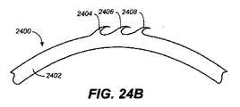
例として、図24Aは、概ね円筒形の支持体(2402)と、アンカー部分(2404)、(2406)、および(2408)とを含むインプラント(2400)を示し、該アンカー部分(2404)、(2406)、および(2408)は、概ね円筒形の支持体から延び、かつ、それと一体で形成されている。インプラント(2400)は、例えば、PEEKチューブなどのポリマーチューブからアンカー部分を切り出すことによって形成され得る。図24Aに示されているように、アンカー部分(2404)、(2406)、および(2408)は、概ね円筒形の支持体(2402)の表面(2410)とほぼ同一の高さになるように配置されている。例えば、インプラント(2400)が、アンカー部分を拘束する送達シースの中に配置されたときに、アンカー部分は、この位置になり得る。図24Bに示されているように、概ね円筒形の支持体(2402)が、曲げられたときに、アンカー部分(2404)、(2406)、および(2408)は、概ね円筒形の支持体から突出し、図24Cに示されているように、それらが標的組織(2412)に留められることを可能にする。 As an example, FIG. 24A shows an implant (2400) that includes a generally cylindrical support (2402) and anchor portions (2404), (2406), and (2408), wherein the anchor portions (2404), ( 2406) and (2408) extend from and are integrally formed with a generally cylindrical support. Implant (2400) may be formed, for example, by cutting an anchor portion from a polymer tube, such as a PEEK tube. As shown in FIG. 24A, the anchor portions (2404), (2406), and (2408) are approximately level with the surface (2410) of the generally cylindrical support (2402). Has been placed. For example, when the implant (2400) is placed in a delivery sheath that constrains the anchor portion, the anchor portion can be in this position. As shown in FIG. 24B, when the generally cylindrical support (2402) is bent, the anchor portions (2404), (2406), and (2408) are removed from the generally cylindrical support. Protrusions and allows them to be clamped to the target tissue (2412) as shown in FIG. 24C.
インプラント(2400)は、概ね円筒形の支持体を含むように示されているが、同様な構成を有する他のインプラントは、非円筒形の支持体を含み得る。さらに、インプラントの一部の変形例は、概ね円筒形の支持体と一体で形成されたアンカー部分に加えて、またはそれの代わりにいずれかで、概ね円筒形の支持体に取り付けられたアンカー部分を含み得る。 Although the implant (2400) is shown to include a generally cylindrical support, other implants having a similar configuration may include a non-cylindrical support. Further, some variations of the implant include an anchor portion attached to the generally cylindrical support, either in addition to or instead of the anchor portion integrally formed with the generally cylindrical support. Can be included.
インプラントの別の変形例が、図25Aに例示されている。図25Aに示されているように、インプラント(2500)は、概ね円筒形の支持体(2502)と、アンカー部分(2504)、(2506)、および(2508)とを含み、該アンカー部分(2504)、(2506)、および(2508)は、概ね円筒形の支持体から延びている。ロッド(2510)は、概ね円筒形の支持体の2つの部分(2512)および(2514)を通って延び、そして、矢印(A3)の方向に引かれることにより、部分(2512)および(2514)をより近づけ得る。ロッド(2510)は、例えば、1つ以上の金属、1つ以上の金属合金、および/または1つ以上のポリマーで形成され得る。ロッド(2510)は、ロッドの端の一方に止め具(2516)を含み、該止め具(2516)は、ロッド(2510)が、部分(2512)および(2514)を通過して引かれることを防止し得る。図25Bに示されているように、ロッド(2510)が、矢印(A3)の方向に引かれると、概ね円筒形の支持体(2502)からのアンカー部分(2504)、(2506)、および(2508)の突出が、向上され、アンカー部分が標的組織(2518)の中に留められることを可能にする。 Another variation of the implant is illustrated in FIG. 25A. As shown in FIG. 25A, implant (2500) includes a generally cylindrical support (2502) and anchor portions (2504), (2506), and (2508), the anchor portion (2504). ), (2506), and (2508) extend from a generally cylindrical support. The rod (2510) extends through the two parts (2512) and (2514) of the generally cylindrical support and is pulled in the direction of the arrow (A3), thereby causing parts (2512) and (2514). Can be closer. The rod (2510) can be formed of, for example, one or more metals, one or more metal alloys, and / or one or more polymers. The rod (2510) includes a stop (2516) at one of the ends of the rod, the stop (2516) allowing the rod (2510) to be pulled through portions (2512) and (2514). Can be prevented. As shown in FIG. 25B, when the rod (2510) is pulled in the direction of the arrow (A3), the anchor portions (2504), (2506), and (2) from the generally cylindrical support (2502) 2508) is improved, allowing the anchor portion to be retained in the target tissue (2518).
インプラントのさらなる例が、図26Aに示されている。図26Aに示されているように、インプラント(2600)は、第1の概ね円筒形の支持体(2602)と、第2の概ね円筒形の支持体(2604)とを含む。第1の概ね円筒形の支持体は、より大きい直径の部分(2606)と、より小さい直径の部分(2608)とを含み、該より小さい直径の部分(2608)に、第2の概ね円筒形の支持体は、入れ子式に接続されている。アンカー部分(2610)、(2612)、(2614)、および(2616)は、第1の概ね円筒形の支持体(2602)から延び、そして、アンカー部分(2620)、(2622)、(2624)、および(2626)は、第2の概ね円筒形の支持体(2604)から延びている。一端において止め具に接続されているテザー(2630)は、第1の概ね円筒形の支持体(2602)と第2の概ね円筒形の支持体(2604)とを通される。シンチングロック(2634)が、テザーの他端においてテザーと可動に係合されている。 A further example of an implant is shown in FIG. 26A. As shown in FIG. 26A, implant (2600) includes a first generally cylindrical support (2602) and a second generally cylindrical support (2604). The first generally cylindrical support includes a larger diameter portion (2606) and a smaller diameter portion (2608) into the second generally cylindrical portion (2608). The supports are connected in a telescopic manner. Anchor portions (2610), (2612), (2614), and (2616) extend from first generally cylindrical support (2602) and anchor portions (2620), (2622), (2624) , And (2626) extend from a second generally cylindrical support (2604). A tether (2630) connected at one end to a stop is threaded through a first generally cylindrical support (2602) and a second generally cylindrical support (2604). A cinching lock (2634) is movably engaged with the tether at the other end of the tether.
図26Bを参照すると、インプラント(2600)の使用中、テザー(2630)が、矢印(A4)の方向に引かれ得、それにより、第1の概ね円筒形の支持体(2602)の端(2636)に対して止め具(2632)を押させる。矢印(A4)の方向にテザー(2630)を引き続けることが、より小さい直径の部分(2608)を、第2の概ね円筒形の支持体(2604)の中にさらに摺動させながら、第1の概ね円筒形の支持体と第2の概ね円筒形の支持体とからのアンカー部分の突出をも向上させる。この突出の向上が、インプラントが標的組織(2638)と比較的容易に係合されることを可能にする。さらに、テザーを引くことはまた、シンチング効果を提供し得る。図26Bに示されるように、所望の量のアンカー部分の突出、および/または所望の量のシンチングが、達成されると、シンチングロック(2634)が、矢印(A5)の方向に動かされて、テザー(2630)を固定することを助け得る。特定の変形例において、シンチングの後、より大きい直径の部分(2606)と第2の概ね円筒形の支持体(2604)とは、互いから約3センチメートル離れ得る。 Referring to FIG. 26B, during use of the implant (2600), the tether (2630) may be pulled in the direction of the arrow (A4), thereby causing the end (2636) of the first generally cylindrical support (2602). ) To push the stopper (2632). Continued pulling of the tether (2630) in the direction of arrow (A4) causes the first portion of the smaller diameter portion (2608) to slide further into the second generally cylindrical support (2604). The anchor portion also protrudes from the generally cylindrical support and the second generally cylindrical support. This enhanced protrusion allows the implant to be relatively easily engaged with the target tissue (2638). In addition, pulling the tether can also provide a cinching effect. As shown in FIG. 26B, once the desired amount of anchor portion protrusion and / or the desired amount of cinching has been achieved, the cinching lock (2634) is moved in the direction of arrow (A5). , Can help fix the tether (2630). In certain variations, after cinching, the larger diameter portion (2606) and the second generally cylindrical support (2604) may be about 3 centimeters away from each other.
インプラント(2600)の概ね円筒形の支持体は、概ね円形の断面を有するように構成されている。しかしながら、一部の変形例において、インプラントは、非円形の断面を有する1つ以上の支持体を含み得る。例えば、図27は、第1の支持体(2702)と第2の支持体(2704)とで形成されたインプラント(2700)を示す。アンカー部分(2706)、(2708)、(2710)、および(2712)が、第1の支持体(2702)から延び、そして、アンカー部分(2714)、(2716)、(2718)、および(2720)が、第2の支持体(2704)から延びている。テザー(2724)は、第1の支持体と第2の支持体とを通され、そして、一端において止め具(2726)に取り付けられている。シンチングロック(2728)は、テザーの他端においてテザー(2724)に可動に取り付けられている。図27に示されるように、第1の支持体(2702)と第2の支持体(2704)とは両方とも、楕円形の断面を有する。これが、例えば、(例えば、アンカー部分が、所望の方向を向いているように)医師が処置の間にインプラントを正しく配向することをより容易にする。楕円形の断面が、記載されているが、三角形、不規則などの他の断面、が使用され得る。さらに、配向の他のインジケータが、使用され得る。例えば、インプラントは、隆起を有する支持体を含み得、該隆起は、医師が標的部位においてインプラントを適切に配向することを助ける。 The generally cylindrical support of the implant (2600) is configured to have a generally circular cross section. However, in some variations, the implant may include one or more supports having a non-circular cross section. For example, FIG. 27 shows an implant (2700) formed of a first support (2702) and a second support (2704). Anchor portions (2706), (2708), (2710), and (2712) extend from first support (2702) and anchor portions (2714), (2716), (2718), and (2720) ) Extends from the second support (2704). The tether (2724) is threaded through the first support and the second support and is attached at one end to the stop (2726). The cinching lock (2728) is movably attached to the tether (2724) at the other end of the tether. As shown in FIG. 27, both the first support (2702) and the second support (2704) have an elliptical cross section. This makes it easier for the physician to orient the implant correctly during the procedure, for example (eg, the anchor portion is oriented in the desired direction). Although elliptical cross-sections are described, other cross-sections such as triangles, irregular, etc. may be used. In addition, other indicators of orientation can be used. For example, the implant can include a support having a ridge that helps the physician to properly orient the implant at the target site.
特定の構成を有するインプラントが、記載されているが、他の構成を有するインプラントが、組織修復処置において使用され得る。例えば、図28は、インプラント(2800)を示し、該インプラント(2800)は、ホルダ(2804)に解放可能に取り付けられたストリップ(2802)と、ストリップ(2802)を上がる方向に徐々に動かされるように構成されたカラー(2806)とで形成されている。カラー(2806)は、フック(2808)および(2810)を含み、該フック(2808)および(2810)は、カラー(2806)がストリップ(2802)を上がる方向に徐々に動かされると、ストリップ(2802)に沿ったカットアウトにスナップ嵌めするように構成されている。ストリップ(2802)は、支持体(2814)を含み、該支持体(2814)において、カットアウトが形成され、そして、アンカー部分(2816)、(2818)、および(2820)が、支持体から延びている。さらに、アンカー部分(2822)、(2824)、および(2826)は、カラー(2806)から延びている。インプラント(2800)の使用中、アンカー部分は、標的組織に留められ得、そして、カラーは、(例えば、プッシャを使用して)ストリップを上がる方向に徐々に動かされることにより、シンチング効果を提供し得る。インプラント(2800)を標的組織に配備する前に、アンカー部分は、ストリップ(2802)の表面およびカラー(2806)の表面と同一の高さ、またはほぼ同一の高さになり得る。インプラント(2800)を標的組織に送達するために使用される送達デバイスは、例えば、シースを含み得、該シースは、アンカー部分を一時的に拘束する。インプラントが、配備されると、アンカー部分は、拘束されなくなり得、そして、ストリップ(2802)および/またはカラー(2806)からより多く突出し得る。一部の変形例において、インプラント(2800)に対して使用される送達デバイスは、バルーンを含み得、そして、インプラント(2800)は、標的組織への送達の間、バルーンの上に配置され得る。標的組織に到達すると、バルーンが、拡張させられることにより、ストリップおよび/またはカラーからアンカー部分の突出を向上させ得る。特定の変形例において、アンカー部分は、プルワイヤーに接続され、該プルワイヤーは、引張られると、ストリップおよび/またはカラーからさらに遠くにアンカー部分を突出させ得る。これらのデバイスや他のデバイスが、単独で、または組み合わせて使用され得ることにより、インプラント(2800)のアンカー部分の突出を向上させ得るので、インプラントは、標的組織とさらに容易に係合され得る。一部の変形例において、インプラントが標的組織と係合した後、ホルダ(2804)は、ストリップ(2802)から取り外され得るので、ストリップ(2802)とカラー(2806)とだけが、標的組織に残る。 While implants having specific configurations have been described, implants having other configurations can be used in tissue repair procedures. For example, FIG. 28 shows an implant (2800) that is releasably attached to a holder (2804) with a strip (2802) that is gradually moved up the strip (2802). And a collar (2806) configured in the above. The collar (2806) includes hooks (2808) and (2810) which, when the collar (2806) is gradually moved up the strip (2802), the strip (2802). ) Is snapped into the cutout along. The strip (2802) includes a support (2814) in which a cutout is formed and anchor portions (2816), (2818), and (2820) extend from the support. ing. In addition, anchor portions (2822), (2824), and (2826) extend from collar (2806). During use of the implant (2800), the anchor portion can be anchored to the target tissue and the collar can be moved gradually up the strip (eg, using a pusher) to provide a cinching effect. obtain. Prior to deploying the implant (2800) to the target tissue, the anchor portion may be at the same height or approximately the same height as the surface of the strip (2802) and the surface of the collar (2806). The delivery device used to deliver the implant (2800) to the target tissue can include, for example, a sheath that temporarily restrains the anchor portion. Once the implant is deployed, the anchor portion can become unconstrained and protrude more from the strip (2802) and / or collar (2806). In some variations, the delivery device used for the implant (2800) may include a balloon, and the implant (2800) may be placed over the balloon during delivery to the target tissue. Upon reaching the target tissue, the balloon can be expanded to improve the protrusion of the anchor portion from the strip and / or collar. In certain variations, the anchor portion is connected to a pull wire that, when pulled, may cause the anchor portion to protrude further from the strip and / or collar. These and other devices can be used alone or in combination to improve the protrusion of the anchor portion of the implant (2800) so that the implant can be more easily engaged with the target tissue. In some variations, after the implant engages the target tissue, the holder (2804) can be removed from the strip (2802) so that only the strip (2802) and the collar (2806) remain in the target tissue. .
インプラントの別の例が、図29に示されている。そこに示されているように、インプラント(2900)は、複数のモジュール(2902)、(2904)、(2906)、(2908)、(2910)、および(2912)を含む。各モジュールは、開口部を有する支持体と、支持体から延びているアンカー部分とで形成されている。例えば、モジュール(2902)は、開口部(2915)を有する支持体(2914)と、支持体(2914)から延びているアンカー部分(2916)とで形成されている。インプラント(2900)はさらに、テザー(2918)を含み、該テザー(2918)は、一端において止め具(2920)に取り付けられている。テザー(2918)は、モジュールの開口部を通され、それにより、モジュールを互いに接続する。インプラントが、送達され、そして、標的組織に配備されると、ストリップ(2922)がまた、モジュールの開口部を通され、そして、モジュールを全体として保持することを助ける。一部の変形例において、ストリップは、バンプおよび/または隆起などの特定の特徴を含み得、該特定の特徴は、モジュールとストリップとの係合を向上させる。インプラント(2900)が、標的組織に送達され、そして、1つ以上のアンカー部分が、標的組織に留められると、ストリップ(2922)は、取り除かれ得るか、または適切な場所に残ることを許容され得る。さらに、テザー(2918)が、矢印(A6)の方向に引かれることにより、シンチング効果を提供し得る。示されているように、止め具(2920)は、モジュール(2902)の開口部(2915)よりも大きいので、テザー(2918)は、偶発的に、モジュール全体を通って引き抜かれること防がれ得る。 Another example of an implant is shown in FIG. As shown therein, implant (2900) includes a plurality of modules (2902), (2904), (2906), (2908), (2910), and (2912). Each module is formed of a support having an opening and an anchor portion extending from the support. For example, module (2902) is formed of a support (2914) having an opening (2915) and an anchor portion (2916) extending from support (2914). The implant (2900) further includes a tether (2918) that is attached to a stop (2920) at one end. The tether (2918) is threaded through the openings in the modules, thereby connecting the modules together. As the implant is delivered and deployed to the target tissue, the strip (2922) is also passed through the opening of the module and helps to hold the module as a whole. In some variations, the strip may include specific features such as bumps and / or ridges, which improve the engagement between the module and the strip. Once the implant (2900) is delivered to the target tissue and one or more anchor portions are secured to the target tissue, the strip (2922) can be removed or allowed to remain in place. obtain. Further, the tether (2918) can be pulled in the direction of arrow (A6) to provide a cinching effect. As shown, the stop (2920) is larger than the opening (2915) of the module (2902), thus preventing the tether (2918) from being accidentally pulled through the entire module. obtain.
インプラントの特定の変形例は、テザーを含み得、テザーが引かれると、テザーが、インプラントのアンカー部分と組織との係合を向上させ得、および/または比較的良好なシンチング効果を提供するように、該テザーは、経路を定められている。例えば、図30は、インプラント(3000)を示し、該インプラント(3000)は、第1の管状支持体(3002)と、第2の管状支持体(3004)とで形成され、該第1の管状支持体(3002)と、該第2の管状支持体(3004)とは、管状部材(3006)によって互いに連結されている。管状部材(3006)は、それの側壁(3010)にアパーチャ(3008)を含む。アンカー部分(3012)および(3014)は、第1の管状支持体(3002)から延び、そして、アンカー部分(3016)および(3018)は、第2の管状支持体(3004)から延びている。テザー(3020)は、第1の管状支持体および第2の管状支持体と、管状部材とを経由する(破線は、テザーがインプラントの内側にあることを示し、そして、実線は、テザーがインプラントの外側にあることを示す)。アンカー部分が、組織に留められ、そして、テザーが、矢印(A7)の方向に引かれると、テザーは、第1の管状支持体と第2の管状支持体とを互いにより近くに引き寄せる。これが、次に、シンチング効果をもたらし得、および/またはアンカー部分と組織との係合を向上させ得る。一般的に、第1の管状支持体(3002)が、最初、第2の管状支持体(3004)に向かって動き始め得、その少し後に、第2の管状支持体が、第1の管状支持体に向かって動き始める。一部の変形例において、テザーが引かれて、所望の量のシンチングを提供した後、第1の管状支持体(3002)の内側のプラグが、テザーを終端させるために使用され得る。 Certain variations of the implant may include a tether so that when the tether is pulled, the tether may improve engagement between the anchor portion of the implant and tissue and / or provide a relatively good cinching effect. In addition, the tether is routed. For example, FIG. 30 shows an implant (3000), which is formed of a first tubular support (3002) and a second tubular support (3004), the first tubular support. The support (3002) and the second tubular support (3004) are connected to each other by a tubular member (3006). Tubular member (3006) includes an aperture (3008) on its sidewall (3010). Anchor portions (3012) and (3014) extend from first tubular support (3002) and anchor portions (3016) and (3018) extend from second tubular support (3004). The tether (3020) goes through the first and second tubular supports and the tubular member (dashed line indicates that the tether is inside the implant and solid line indicates that the tether is the implant) To be outside of). When the anchor portion is fastened to the tissue and the tether is pulled in the direction of arrow (A7), the tether pulls the first tubular support and the second tubular support closer together. This in turn can provide a cinching effect and / or improve engagement between the anchor portion and the tissue. In general, the first tubular support (3002) may initially begin to move toward the second tubular support (3004), and shortly thereafter, the second tubular support is the first tubular support. Start moving towards the body. In some variations, the plug inside the first tubular support (3002) can be used to terminate the tether after the tether is pulled to provide the desired amount of cinching.
図31は、テザーを含むインプラントの別の変形例を示しており、該テザーは、シンチング効果を提供し、および/またはアンカー部分の突出を向上させるように特に経路を定められている。図31に示されているように、インプラント(3100)は、側壁(3101)にアパーチャを有する第1の管状支持体(3102)と、第2の管状支持体(3104)とを含む。第1の管状支持体(3102)と、第2の管状支持体(3104)とは、管状部材(3106)によって互いに接続されている。管状部材(3106)は、それの外側壁(3110)にアパーチャ(3108)を含む。アンカー部分(3112)および(3114)は、第1の管状支持体(3102)から延び、そして、アンカー部分(3116)および(3118)は、第2の管状支持体(3104)から延びている。テザー(3120)は、第1の管状支持体および第2の管状支持体と、管状部材とを経由している(破線は、テザーがインプラントの内側にあることを示し、そして、実線は、テザーがインプラントの外側にあることを示す)。アンカー部分が、組織に留められ、そして、テザーが、矢印(A8)の方向に引かれると、テザーは、第1の管状支持体と第2の管状支持体とを互い向かって引き寄せる。これが、次に、シンチング効果をもたらし得、および/またはアンカー部分と組織との係合を向上させ得る。一般的に、第2の管状支持体(3104)が、最初、第1の管状支持体(3102)に向かって動き始め得、その少し後に、第1の管状支持体が、第2の管状支持体に向かって動き始める。一部の変形例において、テザーが引かれて、所望の量のシンチングを提供した後、結び目が、下に押され得るので、結び目が、アパーチャ(3101)にぶつかり、それにより、テザーを終端させる。特定の変形例において、テザーが引かれることにより、所望の量のシンチングを提供した後、テザーは、第1の管状の支持体(3102)のより多くの範囲を通され、そして、プラグが、第1の管状の支持体(3102)の中に押されることにより、テザーを終端させ得る。 FIG. 31 illustrates another variation of an implant that includes a tether that is specifically routed to provide a cinching effect and / or improve the protrusion of the anchor portion. As shown in FIG. 31, implant (3100) includes a first tubular support (3102) having an aperture in a sidewall (3101) and a second tubular support (3104). The first tubular support (3102) and the second tubular support (3104) are connected to each other by a tubular member (3106). Tubular member (3106) includes an aperture (3108) in its outer wall (3110). Anchor portions (3112) and (3114) extend from the first tubular support (3102), and anchor portions (3116) and (3118) extend from the second tubular support (3104). The tether (3120) is routed through the first and second tubular supports and the tubular member (the dashed line indicates that the tether is inside the implant and the solid line indicates the tether) Is outside the implant). When the anchor portion is fastened to the tissue and the tether is pulled in the direction of arrow (A8), the tether pulls the first tubular support and the second tubular support toward each other. This in turn can provide a cinching effect and / or improve engagement between the anchor portion and the tissue. In general, the second tubular support (3104) may initially begin to move toward the first tubular support (3102), and shortly thereafter, the first tubular support is the second tubular support. Start moving towards the body. In some variations, after the tether has been pulled to provide the desired amount of cinching, the knot can be pushed down so that the knot hits the aperture (3101), thereby terminating the tether. . In a particular variation, after the tether is pulled to provide the desired amount of cinching, the tether is passed through more area of the first tubular support (3102) and the plug is The tether can be terminated by being pushed into the first tubular support (3102).
方法とデバイスとが、例示と例とによって本明細書においてある程度詳細に記載されてきたが、かかる例示やかかる例は、理解を明確にする目的のためだけのものである。特定の変化や特定の改変が、添付の特許請求の範囲の精神と範囲とを逸脱することなく行われ得ることは、本明細書における教示を鑑みて当業者には容易に理解される。例えば、上記の方法や上記のデバイスは、心臓組織に関して記載されてきたが、上記の方法や上記のデバイスは、経皮的に、腹腔鏡用切開を経由して皮膚を通って、または気管を通ってアクセスされ得るあらゆる体の組織に使用されることが想定されていることが理解されるべきである。すなわち、これらの方法やこれらのデバイスが、心臓の解剖学的構造に対してどのように使用されるかに関して本明細書において提供された詳細な記述は、単に、これらの方法やこれらのデバイスがどのように使用され得るかに関する1つの例示的な変形例を示すだけである。例えば、方法は、心臓、様々な血管、嚢、胃などに使用され得る。 Although methods and devices have been described in some detail herein by way of illustration and example, such illustration and example are for purposes of clarity of understanding only. It will be readily apparent to one skilled in the art in view of the teachings herein that certain changes and modifications may be made without departing from the spirit and scope of the appended claims. For example, while the above methods and devices have been described with respect to heart tissue, the above methods and devices can be percutaneously through the skin through a laparoscopic incision or trachea. It should be understood that it is envisioned for use with any body tissue that can be accessed through. That is, the detailed description provided herein regarding how these methods and these devices are used with respect to the anatomy of the heart is merely an illustration of these methods and these devices. Only one exemplary variation on how it can be used is shown. For example, the method can be used on the heart, various blood vessels, sac, stomach and the like.
Claims (64)
を包含する、方法。 Securing an implant to a first region of tissue around a subannular groove of the heart, the implant comprising a support and a first anchor portion extending from the first portion of the support; A method that includes.
該カテーテルから該組織の第1の領域に該インプラントを配備することであって、該インプラントは、支持体と、該支持体の第1の部分から延びている第1のアンカー部分とを備えている、ことと、
を包含する、方法。 Advancing the catheter to a first region of tissue in the vicinity of the subannular groove of the heart;
Deploying the implant from the catheter to a first region of the tissue, the implant comprising a support and a first anchor portion extending from the first portion of the support. And that
Including the method.
該支持体から延びている複数のアンカー部分と
を備えている、インプラントであって、
該複数のアンカー部分は、互いに対して非直線の関係を有する少なくとも3つのアンカー部分を備え、該インプラントは、僧帽弁組織の第1の領域に固定されるように構成されている、インプラント。 A support;
An implant comprising a plurality of anchor portions extending from the support,
The plurality of anchor portions comprises at least three anchor portions having a non-linear relationship with respect to each other, wherein the implant is configured to be secured to a first region of mitral valve tissue.
該支持体から延びている複数のアンカー部分と
を備えている、インプラントであって、
該複数のアンカー部分は、支持体上に非直線のアレイを形成し、そして、該インプラントは、僧帽弁組織の第1の領域に固定されるように構成されている、インプラント。 A support;
An implant comprising a plurality of anchor portions extending from the support,
The plurality of anchor portions form a non-linear array on a support and the implant is configured to be secured to a first region of mitral valve tissue.
Applications Claiming Priority (2)
| Application Number | Priority Date | Filing Date | Title |
|---|---|---|---|
| US11/656,141 US20080177380A1 (en) | 2007-01-19 | 2007-01-19 | Methods and devices for heart tissue repair |
| PCT/US2008/000351 WO2008088716A1 (en) | 2007-01-19 | 2008-01-09 | Methods and devices for heart tissue repair |
Publications (2)
| Publication Number | Publication Date |
|---|---|
| JP2010516333A true JP2010516333A (en) | 2010-05-20 |
| JP2010516333A5 JP2010516333A5 (en) | 2011-02-24 |
Family
ID=39345600
Family Applications (1)
| Application Number | Title | Priority Date | Filing Date |
|---|---|---|---|
| JP2009546400A Pending JP2010516333A (en) | 2007-01-19 | 2008-01-09 | Methods and devices for cardiac tissue repair |
Country Status (7)
| Country | Link |
|---|---|
| US (1) | US20080177380A1 (en) |
| EP (1) | EP2144577A1 (en) |
| JP (1) | JP2010516333A (en) |
| AU (1) | AU2008205666A1 (en) |
| CA (1) | CA2675589A1 (en) |
| IL (1) | IL199797A0 (en) |
| WO (1) | WO2008088716A1 (en) |
Cited By (10)
| Publication number | Priority date | Publication date | Assignee | Title |
|---|---|---|---|---|
| JP2018138190A (en) * | 2012-01-25 | 2018-09-06 | インタクト ヴァスキュラー インコーポレイテッドIntact Vascular, Inc. | Intracavitary device and method |
| US10660771B2 (en) | 2007-12-12 | 2020-05-26 | Intact Vacsular, Inc. | Deployment device for placement of multiple intraluminal surgical staples |
| US10779971B2 (en) | 2009-06-11 | 2020-09-22 | Intact Vascular, Inc. | Endovascular implant |
| US10779969B2 (en) | 2011-06-03 | 2020-09-22 | Intact Vascular, Inc. | Endovascular implant and deployment devices |
| US10779968B2 (en) | 2010-05-29 | 2020-09-22 | Intact Vascular, Inc. | Endoluminal device and method |
| US10799374B2 (en) | 2007-12-12 | 2020-10-13 | Intact Vascular, Inc. | Device and method for tacking plaque to blood vessel wall |
| US10898356B2 (en) | 2015-01-29 | 2021-01-26 | Intact Vascular, Inc. | Delivery device and method of delivery |
| US10993824B2 (en) | 2016-01-01 | 2021-05-04 | Intact Vascular, Inc. | Delivery device and method of delivery |
| US11304836B2 (en) | 2015-01-29 | 2022-04-19 | Intact Vascular, Inc. | Delivery device and method of delivery |
| US11660218B2 (en) | 2017-07-26 | 2023-05-30 | Intact Vascular, Inc. | Delivery device and method of delivery |
Families Citing this family (85)
| Publication number | Priority date | Publication date | Assignee | Title |
|---|---|---|---|---|
| WO2003105670A2 (en) | 2002-01-10 | 2003-12-24 | Guided Delivery Systems, Inc. | Devices and methods for heart valve repair |
| US8641727B2 (en) | 2002-06-13 | 2014-02-04 | Guided Delivery Systems, Inc. | Devices and methods for heart valve repair |
| US8608797B2 (en) | 2005-03-17 | 2013-12-17 | Valtech Cardio Ltd. | Mitral valve treatment techniques |
| US9883943B2 (en) | 2006-12-05 | 2018-02-06 | Valtech Cardio, Ltd. | Implantation of repair devices in the heart |
| US11259924B2 (en) | 2006-12-05 | 2022-03-01 | Valtech Cardio Ltd. | Implantation of repair devices in the heart |
| US9192471B2 (en) * | 2007-01-08 | 2015-11-24 | Millipede, Inc. | Device for translumenal reshaping of a mitral valve annulus |
| US11660190B2 (en) | 2007-03-13 | 2023-05-30 | Edwards Lifesciences Corporation | Tissue anchors, systems and methods, and devices |
| JP2011500221A (en) | 2007-10-19 | 2011-01-06 | ガイデッド デリバリー システムズ, インコーポレイテッド | Tether termination equipment |
| JP2011510797A (en) | 2008-02-06 | 2011-04-07 | ガイデッド デリバリー システムズ, インコーポレイテッド | Multiple window guide tunnel |
| US8382829B1 (en) | 2008-03-10 | 2013-02-26 | Mitralign, Inc. | Method to reduce mitral regurgitation by cinching the commissure of the mitral valve |
| US8096985B2 (en) | 2008-05-07 | 2012-01-17 | Guided Delivery Systems Inc. | Deflectable guide |
| US8323335B2 (en) * | 2008-06-20 | 2012-12-04 | Edwards Lifesciences Corporation | Retaining mechanisms for prosthetic valves and methods for using |
| US20100069930A1 (en) * | 2008-09-16 | 2010-03-18 | VentralFix, Inc. | Method and apparatus for minimally invasive delivery, tensioned deployment and fixation of secondary material prosthetic devices in patient body tissue, including hernia repair within the patient's herniation site |
| CA2740233C (en) | 2008-10-10 | 2017-10-03 | Guided Delivery Systems, Inc. | Termination devices and related methods |
| US8795298B2 (en) | 2008-10-10 | 2014-08-05 | Guided Delivery Systems Inc. | Tether tensioning devices and related methods |
| US20120022638A1 (en) * | 2008-12-17 | 2012-01-26 | Leewood Alan R | Barb for anchoring an implantable medical device within a body vessel |
| WO2012176195A2 (en) * | 2011-06-23 | 2012-12-27 | Valtech Cardio, Ltd. | Closure element for use with annuloplasty structure |
| US8241351B2 (en) | 2008-12-22 | 2012-08-14 | Valtech Cardio, Ltd. | Adjustable partial annuloplasty ring and mechanism therefor |
| US8911494B2 (en) | 2009-05-04 | 2014-12-16 | Valtech Cardio, Ltd. | Deployment techniques for annuloplasty ring |
| US8715342B2 (en) | 2009-05-07 | 2014-05-06 | Valtech Cardio, Ltd. | Annuloplasty ring with intra-ring anchoring |
| US10517719B2 (en) | 2008-12-22 | 2019-12-31 | Valtech Cardio, Ltd. | Implantation of repair devices in the heart |
| WO2010085456A1 (en) | 2009-01-20 | 2010-07-29 | Guided Delivery Systems Inc. | Anchor deployment devices and related methods |
| US8353956B2 (en) | 2009-02-17 | 2013-01-15 | Valtech Cardio, Ltd. | Actively-engageable movement-restriction mechanism for use with an annuloplasty structure |
| US9968452B2 (en) | 2009-05-04 | 2018-05-15 | Valtech Cardio, Ltd. | Annuloplasty ring delivery cathethers |
| WO2013069019A2 (en) | 2011-11-08 | 2013-05-16 | Valtech Cardio, Ltd. | Controlled steering functionality for implant-delivery tool |
| US9180007B2 (en) | 2009-10-29 | 2015-11-10 | Valtech Cardio, Ltd. | Apparatus and method for guide-wire based advancement of an adjustable implant |
| US10098737B2 (en) | 2009-10-29 | 2018-10-16 | Valtech Cardio, Ltd. | Tissue anchor for annuloplasty device |
| WO2011067770A1 (en) | 2009-12-02 | 2011-06-09 | Valtech Cardio, Ltd. | Delivery tool for implantation of spool assembly coupled to a helical anchor |
| US9326870B2 (en) * | 2010-04-23 | 2016-05-03 | Medtronic Vascular, Inc. | Biodegradable stent having non-biodegradable end portions and mechanisms for increased stent hoop strength |
| WO2012019052A2 (en) | 2010-08-04 | 2012-02-09 | Micardia Corporation | Percutaneous transcatheter repair of heart valves |
| US20120053680A1 (en) | 2010-08-24 | 2012-03-01 | Bolling Steven F | Reconfiguring Heart Features |
| US9402721B2 (en) | 2011-06-01 | 2016-08-02 | Valcare, Inc. | Percutaneous transcatheter repair of heart valves via trans-apical access |
| US8858623B2 (en) | 2011-11-04 | 2014-10-14 | Valtech Cardio, Ltd. | Implant having multiple rotational assemblies |
| US10398555B2 (en) * | 2011-12-12 | 2019-09-03 | Cardiac Implants Llc | Magnetically coupled cinching of a loop installed in a valve annulus |
| EP2881083B1 (en) | 2011-12-12 | 2017-03-22 | David Alon | Heart valve repair device |
| US9839519B2 (en) | 2012-02-29 | 2017-12-12 | Valcare, Inc. | Percutaneous annuloplasty system with anterior-posterior adjustment |
| US9180008B2 (en) | 2012-02-29 | 2015-11-10 | Valcare, Inc. | Methods, devices, and systems for percutaneously anchoring annuloplasty rings |
| US10849755B2 (en) | 2012-09-14 | 2020-12-01 | Boston Scientific Scimed, Inc. | Mitral valve inversion prostheses |
| US10543088B2 (en) | 2012-09-14 | 2020-01-28 | Boston Scientific Scimed, Inc. | Mitral valve inversion prostheses |
| WO2014052818A1 (en) | 2012-09-29 | 2014-04-03 | Mitralign, Inc. | Plication lock delivery system and method of use thereof |
| EP3517052A1 (en) | 2012-10-23 | 2019-07-31 | Valtech Cardio, Ltd. | Controlled steering functionality for implant-delivery tool |
| WO2014064695A2 (en) | 2012-10-23 | 2014-05-01 | Valtech Cardio, Ltd. | Percutaneous tissue anchor techniques |
| US9730793B2 (en) | 2012-12-06 | 2017-08-15 | Valtech Cardio, Ltd. | Techniques for guide-wire based advancement of a tool |
| WO2014134183A1 (en) | 2013-02-26 | 2014-09-04 | Mitralign, Inc. | Devices and methods for percutaneous tricuspid valve repair |
| US10449333B2 (en) | 2013-03-14 | 2019-10-22 | Valtech Cardio, Ltd. | Guidewire feeder |
| EP3804646A1 (en) | 2013-03-15 | 2021-04-14 | Valcare, Inc. | Systems for delivery of annuloplasty rings |
| EP2968847B1 (en) | 2013-03-15 | 2023-03-08 | Edwards Lifesciences Corporation | Translation catheter systems |
| US10813751B2 (en) | 2013-05-22 | 2020-10-27 | Valcare, Inc. | Transcatheter prosthetic valve for mitral or tricuspid valve replacement |
| EP3003187B1 (en) | 2013-05-24 | 2023-11-08 | Valcare, Inc. | Heart and peripheral vascular valve replacement in conjunction with a support ring |
| CA3005848C (en) | 2013-06-06 | 2020-03-24 | David Alon | Heart valve repair and replacement |
| US11058417B2 (en) | 2013-06-28 | 2021-07-13 | Valcare, Inc. | Device, system, and method to secure an article to a tissue |
| US10070857B2 (en) | 2013-08-31 | 2018-09-11 | Mitralign, Inc. | Devices and methods for locating and implanting tissue anchors at mitral valve commissure |
| US10299793B2 (en) | 2013-10-23 | 2019-05-28 | Valtech Cardio, Ltd. | Anchor magazine |
| US9610162B2 (en) | 2013-12-26 | 2017-04-04 | Valtech Cardio, Ltd. | Implantation of flexible implant |
| US9180005B1 (en) | 2014-07-17 | 2015-11-10 | Millipede, Inc. | Adjustable endolumenal mitral valve ring |
| EP4331503A2 (en) | 2014-10-14 | 2024-03-06 | Edwards Lifesciences Innovation (Israel) Ltd. | Leaflet-restraining techniques |
| WO2016130991A1 (en) | 2015-02-13 | 2016-08-18 | Millipede, Inc. | Valve replacement using rotational anchors |
| EP4292551A3 (en) | 2015-03-05 | 2024-01-31 | Ancora Heart, Inc. | Devices of visualizing and determining depth of penetration in cardiac tissue |
| US20160256269A1 (en) | 2015-03-05 | 2016-09-08 | Mitralign, Inc. | Devices for treating paravalvular leakage and methods use thereof |
| CN114515173A (en) | 2015-04-30 | 2022-05-20 | 瓦尔泰克卡迪欧有限公司 | Valvuloplasty techniques |
| EP3294218B1 (en) | 2015-05-12 | 2022-02-09 | Ancora Heart, Inc. | Device for releasing catheters from cardiac structures |
| EP3539509B1 (en) | 2015-06-01 | 2021-07-07 | Edwards Lifesciences Corporation | Cardiac valve repair devices configured for percutaneous delivery |
| US10335275B2 (en) | 2015-09-29 | 2019-07-02 | Millipede, Inc. | Methods for delivery of heart valve devices using intravascular ultrasound imaging |
| US10507020B2 (en) | 2015-10-15 | 2019-12-17 | Tepha, Inc. | Implantable fastener for attachment of a medical device to tissue |
| CN111329541B (en) | 2015-11-17 | 2023-09-19 | 波士顿科学国际有限公司 | Implantable device and delivery system for reshaping a heart valve annulus |
| US10751182B2 (en) | 2015-12-30 | 2020-08-25 | Edwards Lifesciences Corporation | System and method for reshaping right heart |
| US10828160B2 (en) | 2015-12-30 | 2020-11-10 | Edwards Lifesciences Corporation | System and method for reducing tricuspid regurgitation |
| US10702274B2 (en) | 2016-05-26 | 2020-07-07 | Edwards Lifesciences Corporation | Method and system for closing left atrial appendage |
| CN107753153B (en) | 2016-08-15 | 2022-05-31 | 沃卡尔有限公司 | Device and method for treating heart valve insufficiency |
| CN110381887B (en) | 2017-02-10 | 2022-03-29 | 波士顿科学国际有限公司 | Implantable device and delivery system for remodeling a heart valve annulus |
| CN108618871A (en) | 2017-03-17 | 2018-10-09 | 沃卡尔有限公司 | Bicuspid valve with multi-direction anchor portion or tricuspid valve repair system |
| CN106821548B (en) * | 2017-04-01 | 2020-11-03 | 上海纽脉医疗科技有限公司 | Transcatheter artificial mitral valve annuloplasty ring device and system |
| US11045627B2 (en) | 2017-04-18 | 2021-06-29 | Edwards Lifesciences Corporation | Catheter system with linear actuation control mechanism |
| US10835221B2 (en) | 2017-11-02 | 2020-11-17 | Valtech Cardio, Ltd. | Implant-cinching devices and systems |
| US11135062B2 (en) | 2017-11-20 | 2021-10-05 | Valtech Cardio Ltd. | Cinching of dilated heart muscle |
| WO2019145947A1 (en) * | 2018-01-24 | 2019-08-01 | Valtech Cardio, Ltd. | Contraction of an annuloplasty structure |
| WO2019145941A1 (en) | 2018-01-26 | 2019-08-01 | Valtech Cardio, Ltd. | Techniques for facilitating heart valve tethering and chord replacement |
| US11026791B2 (en) | 2018-03-20 | 2021-06-08 | Medtronic Vascular, Inc. | Flexible canopy valve repair systems and methods of use |
| US11285003B2 (en) | 2018-03-20 | 2022-03-29 | Medtronic Vascular, Inc. | Prolapse prevention device and methods of use thereof |
| EP3820406B1 (en) | 2018-07-12 | 2023-12-20 | Edwards Lifesciences Innovation (Israel) Ltd. | Annuloplasty systems and locking tools therefor |
| CN113613593A (en) | 2018-12-03 | 2021-11-05 | 沃卡尔有限公司 | Stabilization and adjustment tool for controlling minimally invasive mitral/tricuspid valve repair systems |
| EP3998969A4 (en) | 2019-07-15 | 2023-08-02 | Ancora Heart, Inc. | Devices and methods for tether cutting |
| EP3998995A4 (en) | 2019-07-15 | 2023-08-23 | ValCare, Inc. | Transcatheter bio-prosthesis member and support structure |
| KR20220122966A (en) | 2019-10-29 | 2022-09-05 | 에드워즈 라이프사이언시스 이노베이션 (이스라엘) 리미티드 | Annuloplasty and Tissue Anchor Techniques |
| EP3875059A1 (en) | 2020-03-03 | 2021-09-08 | AVVie GmbH | Annuloplasty device |
Citations (13)
| Publication number | Priority date | Publication date | Assignee | Title |
|---|---|---|---|---|
| JPH0588612B2 (en) * | 1985-09-23 | 1993-12-22 | Abion Maruseru Datsusoo Buruge Abiashion | |
| JPH09508537A (en) * | 1993-12-17 | 1997-09-02 | オートジェニックス | Self-organizing heart valve stent |
| US5855601A (en) * | 1996-06-21 | 1999-01-05 | The Trustees Of Columbia University In The City Of New York | Artificial heart valve and method and device for implanting the same |
| US6355030B1 (en) * | 1998-09-25 | 2002-03-12 | Cardiothoracic Systems, Inc. | Instruments and methods employing thermal energy for the repair and replacement of cardiac valves |
| JP2003503103A (en) * | 1999-06-25 | 2003-01-28 | バヒド サーダット, | Apparatus and method for treating tissue |
| JP2003524504A (en) * | 2000-02-28 | 2003-08-19 | フラウンホーファー−ゲゼルシャフト ツール フエルデルング デア アンゲヴァンテン フォルシュング エー.ファオ. | Implantable artificial heart valve fixation system |
| US20030199975A1 (en) * | 2000-05-22 | 2003-10-23 | Shlomo Gabbay | Low invasive implantable cardiac prosthesis and method for helping improve operation of a heart valve |
| JP2004514467A (en) * | 2000-06-26 | 2004-05-20 | レックス メディカル リミテッド パートナーシップ | Vascular device for approximating leaflet-like leaflets |
| JP2005523738A (en) * | 2001-12-21 | 2005-08-11 | シムチャ ミロ | Annuloplasty ring transplantation system |
| WO2005087139A1 (en) * | 2004-03-15 | 2005-09-22 | Baker Medical Research Institute | Treating valve failure |
| WO2005112827A2 (en) * | 2004-05-14 | 2005-12-01 | Ample Medical, Inc. | Devices, systems, and methods for reshaping a heart valve annulus |
| JP2005537067A (en) * | 2002-08-29 | 2005-12-08 | エムディー3 テクノロジーズ エルエルシー | Implantable device for controlling an anatomical orifice or lumen |
| JP4551088B2 (en) * | 2001-09-26 | 2010-09-22 | エドワーズ ライフサイエンシーズ コーポレイション | Thin heart valve suture ring |
Family Cites Families (89)
| Publication number | Priority date | Publication date | Assignee | Title |
|---|---|---|---|---|
| US2108206A (en) * | 1937-03-09 | 1938-02-15 | Lillian Pearl Mecker | Tenaculum |
| NL143127B (en) * | 1969-02-04 | 1974-09-16 | Rhone Poulenc Sa | REINFORCEMENT DEVICE FOR A DEFECTIVE HEART VALVE. |
| US3727614A (en) * | 1971-05-13 | 1973-04-17 | Merck & Co Inc | Multiple dosage inoculator |
| US4014492A (en) * | 1975-06-11 | 1977-03-29 | Senco Products, Inc. | Surgical staple |
| US4069825A (en) * | 1976-01-28 | 1978-01-24 | Taichiro Akiyama | Surgical thread and cutting apparatus for the same |
| US4169303A (en) * | 1976-11-24 | 1979-10-02 | Lemelson Jerome H | Fastening materials |
| US4726371A (en) * | 1982-02-09 | 1988-02-23 | Gibbens Everett N | Surgical cutting instrument |
| CA1176130A (en) * | 1982-03-31 | 1984-10-16 | Mary K. Lee | Suture cutter and extractor |
| US5084058A (en) * | 1990-04-25 | 1992-01-28 | Mitek Surgical Products, Inc. | Suture rundown tool and cutter system |
| US5078731A (en) * | 1990-06-05 | 1992-01-07 | Hayhurst John O | Suture clip |
| US5103804A (en) * | 1990-07-03 | 1992-04-14 | Boston Scientific Corporation | Expandable tip hemostatic probes and the like |
| US5584803A (en) * | 1991-07-16 | 1996-12-17 | Heartport, Inc. | System for cardiac procedures |
| US5735290A (en) * | 1993-02-22 | 1998-04-07 | Heartport, Inc. | Methods and systems for performing thoracoscopic coronary bypass and other procedures |
| US6183469B1 (en) * | 1997-08-27 | 2001-02-06 | Arthrocare Corporation | Electrosurgical systems and methods for the removal of pacemaker leads |
| US5306296A (en) * | 1992-08-21 | 1994-04-26 | Medtronic, Inc. | Annuloplasty and suture rings |
| US5234448A (en) * | 1992-02-28 | 1993-08-10 | Shadyside Hospital | Method and apparatus for connecting and closing severed blood vessels |
| US5383905A (en) * | 1992-10-09 | 1995-01-24 | United States Surgical Corporation | Suture loop locking device |
| US5383897A (en) * | 1992-10-19 | 1995-01-24 | Shadyside Hospital | Method and apparatus for closing blood vessel punctures |
| US5718725A (en) * | 1992-12-03 | 1998-02-17 | Heartport, Inc. | Devices and methods for intracardiac procedures |
| US5409483A (en) * | 1993-01-22 | 1995-04-25 | Jeffrey H. Reese | Direct visualization surgical probe |
| US6010531A (en) * | 1993-02-22 | 2000-01-04 | Heartport, Inc. | Less-invasive devices and methods for cardiac valve surgery |
| US5409499A (en) * | 1993-06-18 | 1995-04-25 | Ethicon, Inc. | Biocompatible suture knot clip |
| US5640955A (en) * | 1995-02-14 | 1997-06-24 | Daig Corporation | Guiding introducers for use in the treatment of accessory pathways around the mitral valve using a retrograde approach |
| US5591194A (en) * | 1994-02-18 | 1997-01-07 | C. R. Bard, Inc. | Telescoping balloon catheter and method of use |
| US5536270A (en) * | 1994-02-24 | 1996-07-16 | Pioneer Laboratories, Inc. | Cable system for bone securance |
| US5593435A (en) * | 1994-07-29 | 1997-01-14 | Baxter International Inc. | Distensible annuloplasty ring for surgical remodelling of an atrioventricular valve and nonsurgical method for post-implantation distension thereof to accommodate patient growth |
| US5593424A (en) * | 1994-08-10 | 1997-01-14 | Segmed, Inc. | Apparatus and method for reducing and stabilizing the circumference of a vascular structure |
| WO1996008208A1 (en) * | 1994-09-16 | 1996-03-21 | Biopsys Medical, Inc. | Methods and devices for defining and marking tissue |
| US6171329B1 (en) * | 1994-12-19 | 2001-01-09 | Gore Enterprise Holdings, Inc. | Self-expanding defect closure device and method of making and using |
| US5695505A (en) * | 1995-03-09 | 1997-12-09 | Yoon; Inbae | Multifunctional spring clips and cartridges and applicators therefor |
| US5860992A (en) * | 1996-01-31 | 1999-01-19 | Heartport, Inc. | Endoscopic suturing devices and methods |
| US5716370A (en) * | 1996-02-23 | 1998-02-10 | Williamson, Iv; Warren | Means for replacing a heart valve in a minimally invasive manner |
| US5735877A (en) * | 1996-02-28 | 1998-04-07 | Pagedas; Anthony C. | Self locking suture lock |
| US5860993A (en) * | 1996-09-25 | 1999-01-19 | Medworks Corp. | Suture cutter |
| US6406420B1 (en) * | 1997-01-02 | 2002-06-18 | Myocor, Inc. | Methods and devices for improving cardiac function in hearts |
| US6050936A (en) * | 1997-01-02 | 2000-04-18 | Myocor, Inc. | Heart wall tension reduction apparatus |
| US6045497A (en) * | 1997-01-02 | 2000-04-04 | Myocor, Inc. | Heart wall tension reduction apparatus and method |
| US5879371A (en) * | 1997-01-09 | 1999-03-09 | Elective Vascular Interventions, Inc. | Ferruled loop surgical fasteners, instruments, and methods for minimally invasive vascular and endoscopic surgery |
| US6015428A (en) * | 1997-06-03 | 2000-01-18 | Anthony C. Pagedas | Integrally formed suture and suture lock |
| US6332893B1 (en) * | 1997-12-17 | 2001-12-25 | Myocor, Inc. | Valve to myocardium tension members device and method |
| US6197017B1 (en) * | 1998-02-24 | 2001-03-06 | Brock Rogers Surgical, Inc. | Articulated apparatus for telemanipulator system |
| US6514265B2 (en) * | 1999-03-01 | 2003-02-04 | Coalescent Surgical, Inc. | Tissue connector apparatus with cable release |
| US6260552B1 (en) * | 1998-07-29 | 2001-07-17 | Myocor, Inc. | Transventricular implant tools and devices |
| ATE492219T1 (en) * | 1999-04-09 | 2011-01-15 | Evalve Inc | DEVICE FOR HEART VALVE OPERATION |
| US10327743B2 (en) * | 1999-04-09 | 2019-06-25 | Evalve, Inc. | Device and methods for endoscopic annuloplasty |
| US7160312B2 (en) * | 1999-06-25 | 2007-01-09 | Usgi Medical, Inc. | Implantable artificial partition and methods of use |
| US6991643B2 (en) * | 2000-12-20 | 2006-01-31 | Usgi Medical Inc. | Multi-barbed device for retaining tissue in apposition and methods of use |
| US6626899B2 (en) * | 1999-06-25 | 2003-09-30 | Nidus Medical, Llc | Apparatus and methods for treating tissue |
| FR2799364B1 (en) * | 1999-10-12 | 2001-11-23 | Jacques Seguin | MINIMALLY INVASIVE CANCELING DEVICE |
| GB2359024A (en) * | 2000-02-09 | 2001-08-15 | Anson Medical Ltd | Fixator for arteries |
| US6533753B1 (en) * | 2000-04-07 | 2003-03-18 | Philip Haarstad | Apparatus and method for the treatment of an occluded lumen |
| US7172615B2 (en) * | 2000-05-19 | 2007-02-06 | Coapt Systems, Inc. | Remotely anchored tissue fixation device |
| DE60132005T2 (en) * | 2000-06-23 | 2008-12-04 | Viacor Inc., Wilmington | AUTOMATIC WRINKLE FOLDING FOR MITRAL LAPPEN REPAIR |
| US6409758B2 (en) * | 2000-07-27 | 2002-06-25 | Edwards Lifesciences Corporation | Heart valve holder for constricting the valve commissures and methods of use |
| US6524338B1 (en) * | 2000-08-25 | 2003-02-25 | Steven R. Gundry | Method and apparatus for stapling an annuloplasty band in-situ |
| AU2001296442A1 (en) * | 2000-09-29 | 2002-04-08 | Tricardia, L.L.C. | Venous valvuloplasty device |
| US6997931B2 (en) * | 2001-02-02 | 2006-02-14 | Lsi Solutions, Inc. | System for endoscopic suturing |
| US20060069429A1 (en) * | 2001-04-24 | 2006-03-30 | Spence Paul A | Tissue fastening systems and methods utilizing magnetic guidance |
| US6619291B2 (en) * | 2001-04-24 | 2003-09-16 | Edwin J. Hlavka | Method and apparatus for catheter-based annuloplasty |
| US6676702B2 (en) * | 2001-05-14 | 2004-01-13 | Cardiac Dimensions, Inc. | Mitral valve therapy assembly and method |
| US7033379B2 (en) * | 2001-06-08 | 2006-04-25 | Incisive Surgical, Inc. | Suture lock having non-through bore capture zone |
| US20030060813A1 (en) * | 2001-09-22 | 2003-03-27 | Loeb Marvin P. | Devices and methods for safely shrinking tissues surrounding a duct, hollow organ or body cavity |
| WO2003105670A2 (en) * | 2002-01-10 | 2003-12-24 | Guided Delivery Systems, Inc. | Devices and methods for heart valve repair |
| US7004958B2 (en) * | 2002-03-06 | 2006-02-28 | Cardiac Dimensions, Inc. | Transvenous staples, assembly and method for mitral valve repair |
| US6699263B2 (en) * | 2002-04-05 | 2004-03-02 | Cook Incorporated | Sliding suture anchor |
| US20050107811A1 (en) * | 2002-06-13 | 2005-05-19 | Guided Delivery Systems, Inc. | Delivery devices and methods for heart valve repair |
| US7666193B2 (en) * | 2002-06-13 | 2010-02-23 | Guided Delivery Sytems, Inc. | Delivery devices and methods for heart valve repair |
| US7758637B2 (en) * | 2003-02-06 | 2010-07-20 | Guided Delivery Systems, Inc. | Delivery devices and methods for heart valve repair |
| US7753858B2 (en) * | 2002-06-13 | 2010-07-13 | Guided Delivery Systems, Inc. | Delivery devices and methods for heart valve repair |
| US7883538B2 (en) * | 2002-06-13 | 2011-02-08 | Guided Delivery Systems Inc. | Methods and devices for termination |
| US20060122633A1 (en) * | 2002-06-13 | 2006-06-08 | John To | Methods and devices for termination |
| US7753922B2 (en) * | 2003-09-04 | 2010-07-13 | Guided Delivery Systems, Inc. | Devices and methods for cardiac annulus stabilization and treatment |
| AU2003272288A1 (en) * | 2002-09-06 | 2004-03-29 | C.R. Bard, Inc. | Tissue capturing devices |
| US7247134B2 (en) * | 2002-11-12 | 2007-07-24 | Myocor, Inc. | Devices and methods for heart valve treatment |
| US7182769B2 (en) * | 2003-07-25 | 2007-02-27 | Medtronic, Inc. | Sealing clip, delivery systems, and methods |
| US7837710B2 (en) * | 2003-09-10 | 2010-11-23 | Linvatec Corporation | Knotless suture anchor |
| US7655040B2 (en) * | 2003-11-12 | 2010-02-02 | Medtronic Vascular, Inc. | Cardiac valve annulus reduction system |
| US20050273138A1 (en) * | 2003-12-19 | 2005-12-08 | Guided Delivery Systems, Inc. | Devices and methods for anchoring tissue |
| US7431726B2 (en) * | 2003-12-23 | 2008-10-07 | Mitralign, Inc. | Tissue fastening systems and methods utilizing magnetic guidance |
| US20060015144A1 (en) * | 2004-07-19 | 2006-01-19 | Vascular Control Systems, Inc. | Uterine artery occlusion staple |
| US8864823B2 (en) * | 2005-03-25 | 2014-10-21 | StJude Medical, Cardiology Division, Inc. | Methods and apparatus for controlling the internal circumference of an anatomic orifice or lumen |
| US7344544B2 (en) * | 2005-03-28 | 2008-03-18 | Cardica, Inc. | Vascular closure system |
| CA2610796C (en) * | 2005-06-02 | 2014-01-07 | Cordis Corporation | Patent foramen ovale closure device |
| US20070005394A1 (en) * | 2005-06-07 | 2007-01-04 | Up Todate Inc. | Method and apparatus for managing medical order sets |
| US8252005B2 (en) * | 2005-06-30 | 2012-08-28 | Edwards Lifesciences Corporation | System, apparatus, and method for fastening tissue |
| US8951285B2 (en) * | 2005-07-05 | 2015-02-10 | Mitralign, Inc. | Tissue anchor, anchoring system and methods of using the same |
| US20070055206A1 (en) * | 2005-08-10 | 2007-03-08 | Guided Delivery Systems, Inc. | Methods and devices for deployment of tissue anchors |
| US9492277B2 (en) * | 2005-08-30 | 2016-11-15 | Mayo Foundation For Medical Education And Research | Soft body tissue remodeling methods and apparatus |
| JP2011500221A (en) * | 2007-10-19 | 2011-01-06 | ガイデッド デリバリー システムズ, インコーポレイテッド | Tether termination equipment |
-
2007
- 2007-01-19 US US11/656,141 patent/US20080177380A1/en not_active Abandoned
-
2008
- 2008-01-09 JP JP2009546400A patent/JP2010516333A/en active Pending
- 2008-01-09 AU AU2008205666A patent/AU2008205666A1/en not_active Abandoned
- 2008-01-09 EP EP08705550A patent/EP2144577A1/en not_active Withdrawn
- 2008-01-09 CA CA002675589A patent/CA2675589A1/en not_active Abandoned
- 2008-01-09 WO PCT/US2008/000351 patent/WO2008088716A1/en active Application Filing
-
2009
- 2009-07-09 IL IL199797A patent/IL199797A0/en unknown
Patent Citations (15)
| Publication number | Priority date | Publication date | Assignee | Title |
|---|---|---|---|---|
| JPH0588612B2 (en) * | 1985-09-23 | 1993-12-22 | Abion Maruseru Datsusoo Buruge Abiashion | |
| JPH09508537A (en) * | 1993-12-17 | 1997-09-02 | オートジェニックス | Self-organizing heart valve stent |
| US5855601A (en) * | 1996-06-21 | 1999-01-05 | The Trustees Of Columbia University In The City Of New York | Artificial heart valve and method and device for implanting the same |
| US6355030B1 (en) * | 1998-09-25 | 2002-03-12 | Cardiothoracic Systems, Inc. | Instruments and methods employing thermal energy for the repair and replacement of cardiac valves |
| JP2003503103A (en) * | 1999-06-25 | 2003-01-28 | バヒド サーダット, | Apparatus and method for treating tissue |
| JP2003524504A (en) * | 2000-02-28 | 2003-08-19 | フラウンホーファー−ゲゼルシャフト ツール フエルデルング デア アンゲヴァンテン フォルシュング エー.ファオ. | Implantable artificial heart valve fixation system |
| US20030199975A1 (en) * | 2000-05-22 | 2003-10-23 | Shlomo Gabbay | Low invasive implantable cardiac prosthesis and method for helping improve operation of a heart valve |
| JP2004514467A (en) * | 2000-06-26 | 2004-05-20 | レックス メディカル リミテッド パートナーシップ | Vascular device for approximating leaflet-like leaflets |
| JP4551088B2 (en) * | 2001-09-26 | 2010-09-22 | エドワーズ ライフサイエンシーズ コーポレイション | Thin heart valve suture ring |
| JP2005523738A (en) * | 2001-12-21 | 2005-08-11 | シムチャ ミロ | Annuloplasty ring transplantation system |
| JP4230915B2 (en) * | 2001-12-21 | 2009-02-25 | シムチャ ミロ | Annuloplasty ring transplantation system |
| JP2005537067A (en) * | 2002-08-29 | 2005-12-08 | エムディー3 テクノロジーズ エルエルシー | Implantable device for controlling an anatomical orifice or lumen |
| WO2005087139A1 (en) * | 2004-03-15 | 2005-09-22 | Baker Medical Research Institute | Treating valve failure |
| WO2005112827A2 (en) * | 2004-05-14 | 2005-12-01 | Ample Medical, Inc. | Devices, systems, and methods for reshaping a heart valve annulus |
| JP2007536989A (en) * | 2004-05-14 | 2007-12-20 | アンプル メディカル, インコーポレイテッド | Device, system and method for reconstructing an annulus of a heart valve |
Cited By (12)
| Publication number | Priority date | Publication date | Assignee | Title |
|---|---|---|---|---|
| US10660771B2 (en) | 2007-12-12 | 2020-05-26 | Intact Vacsular, Inc. | Deployment device for placement of multiple intraluminal surgical staples |
| US10799374B2 (en) | 2007-12-12 | 2020-10-13 | Intact Vascular, Inc. | Device and method for tacking plaque to blood vessel wall |
| US10835395B2 (en) | 2007-12-12 | 2020-11-17 | Intact Vascular, Inc. | Method of treating atherosclerotic occlusive disease |
| US10779971B2 (en) | 2009-06-11 | 2020-09-22 | Intact Vascular, Inc. | Endovascular implant |
| US10888443B2 (en) | 2009-06-11 | 2021-01-12 | Intact Vascular, Inc. | Device for holding plaque to blood vessel wall |
| US10779968B2 (en) | 2010-05-29 | 2020-09-22 | Intact Vascular, Inc. | Endoluminal device and method |
| US10779969B2 (en) | 2011-06-03 | 2020-09-22 | Intact Vascular, Inc. | Endovascular implant and deployment devices |
| JP2018138190A (en) * | 2012-01-25 | 2018-09-06 | インタクト ヴァスキュラー インコーポレイテッドIntact Vascular, Inc. | Intracavitary device and method |
| US10898356B2 (en) | 2015-01-29 | 2021-01-26 | Intact Vascular, Inc. | Delivery device and method of delivery |
| US11304836B2 (en) | 2015-01-29 | 2022-04-19 | Intact Vascular, Inc. | Delivery device and method of delivery |
| US10993824B2 (en) | 2016-01-01 | 2021-05-04 | Intact Vascular, Inc. | Delivery device and method of delivery |
| US11660218B2 (en) | 2017-07-26 | 2023-05-30 | Intact Vascular, Inc. | Delivery device and method of delivery |
Also Published As
| Publication number | Publication date |
|---|---|
| US20080177380A1 (en) | 2008-07-24 |
| AU2008205666A1 (en) | 2008-07-24 |
| CA2675589A1 (en) | 2008-07-24 |
| WO2008088716A1 (en) | 2008-07-24 |
| IL199797A0 (en) | 2010-04-15 |
| EP2144577A1 (en) | 2010-01-20 |
Similar Documents
| Publication | Publication Date | Title |
|---|---|---|
| JP2010516333A (en) | Methods and devices for cardiac tissue repair | |
| US20220323207A1 (en) | Vascular implant and delivery system | |
| US11589988B2 (en) | Valvular insufficiency repair device and method | |
| US8070802B2 (en) | Mitral valve system | |
| CN111050668A (en) | Tissue grasping device and related methods | |
| JP2019507664A (en) | Heart valve replacement system and method | |
| US20220054259A1 (en) | Flexible Anchor For Prosthetic Heart Valve | |
| US20230372085A1 (en) | Devices, Systems, and Methods for an Implantable Heart-Valve Adapter |
Legal Events
| Date | Code | Title | Description |
|---|---|---|---|
| A521 | Request for written amendment filed |
Free format text: JAPANESE INTERMEDIATE CODE: A523 Effective date: 20101228 |
|
| A621 | Written request for application examination |
Free format text: JAPANESE INTERMEDIATE CODE: A621 Effective date: 20101228 |
|
| A131 | Notification of reasons for refusal |
Free format text: JAPANESE INTERMEDIATE CODE: A131 Effective date: 20120815 |
|
| A02 | Decision of refusal |
Free format text: JAPANESE INTERMEDIATE CODE: A02 Effective date: 20130129 |