JP2010515537A - Lead wire having an expandable fixing structure - Google Patents
Lead wire having an expandable fixing structure Download PDFInfo
- Publication number
- JP2010515537A JP2010515537A JP2009545629A JP2009545629A JP2010515537A JP 2010515537 A JP2010515537 A JP 2010515537A JP 2009545629 A JP2009545629 A JP 2009545629A JP 2009545629 A JP2009545629 A JP 2009545629A JP 2010515537 A JP2010515537 A JP 2010515537A
- Authority
- JP
- Japan
- Prior art keywords
- lead
- distal end
- portal
- inflatable member
- proximal end
- Prior art date
- Legal status (The legal status is an assumption and is not a legal conclusion. Google has not performed a legal analysis and makes no representation as to the accuracy of the status listed.)
- Pending
Links
Images


Classifications
-
- A—HUMAN NECESSITIES
- A61—MEDICAL OR VETERINARY SCIENCE; HYGIENE
- A61N—ELECTROTHERAPY; MAGNETOTHERAPY; RADIATION THERAPY; ULTRASOUND THERAPY
- A61N1/00—Electrotherapy; Circuits therefor
- A61N1/02—Details
- A61N1/04—Electrodes
- A61N1/05—Electrodes for implantation or insertion into the body, e.g. heart electrode
- A61N1/056—Transvascular endocardial electrode systems
- A61N1/057—Anchoring means; Means for fixing the head inside the heart
-
- A—HUMAN NECESSITIES
- A61—MEDICAL OR VETERINARY SCIENCE; HYGIENE
- A61M—DEVICES FOR INTRODUCING MEDIA INTO, OR ONTO, THE BODY; DEVICES FOR TRANSDUCING BODY MEDIA OR FOR TAKING MEDIA FROM THE BODY; DEVICES FOR PRODUCING OR ENDING SLEEP OR STUPOR
- A61M25/00—Catheters; Hollow probes
- A61M25/10—Balloon catheters
-
- A—HUMAN NECESSITIES
- A61—MEDICAL OR VETERINARY SCIENCE; HYGIENE
- A61M—DEVICES FOR INTRODUCING MEDIA INTO, OR ONTO, THE BODY; DEVICES FOR TRANSDUCING BODY MEDIA OR FOR TAKING MEDIA FROM THE BODY; DEVICES FOR PRODUCING OR ENDING SLEEP OR STUPOR
- A61M25/00—Catheters; Hollow probes
- A61M25/01—Introducing, guiding, advancing, emplacing or holding catheters
- A61M25/02—Holding devices, e.g. on the body
- A61M25/04—Holding devices, e.g. on the body in the body, e.g. expansible
-
- A—HUMAN NECESSITIES
- A61—MEDICAL OR VETERINARY SCIENCE; HYGIENE
- A61N—ELECTROTHERAPY; MAGNETOTHERAPY; RADIATION THERAPY; ULTRASOUND THERAPY
- A61N1/00—Electrotherapy; Circuits therefor
- A61N1/02—Details
- A61N1/04—Electrodes
- A61N1/05—Electrodes for implantation or insertion into the body, e.g. heart electrode
- A61N1/056—Transvascular endocardial electrode systems
- A61N2001/0585—Coronary sinus electrodes
Abstract
心臓の左側(すなわち、左心室)を刺激するときに使用するよう構成された医療用電気リード線。一実施形態では、リード線は内側表面を含む長尺状のリード線本体を含む。膨張可能部材は、本体の近位端と遠位端との間で本体の外側表面上に配設され、膨張すると、冠状静脈洞または冠状静脈の表面に半径方向力を与えかつ摩擦係合して、冠状静脈洞または冠状静脈の表面にリード線の遠位端を固着するようになっている。リード線は、さらに、近位端から遠位端へ向かって延在する導電性部材と、導電性部材と本体の内側表面との間に配置される内側絶縁層とを含む。内側絶縁層と本体の内側表面との間の分離は、膨張可能部材に連通する膨張管腔を画定する。A medical electrical lead configured for use in stimulating the left side of the heart (ie, the left ventricle). In one embodiment, the lead includes an elongated lead body including an inner surface. An inflatable member is disposed on the outer surface of the body between the proximal and distal ends of the body, and when inflated, applies a radial force and frictionally engages the surface of the coronary sinus or coronary vein. Thus, the distal end of the lead wire is secured to the surface of the coronary sinus or coronary vein. The lead further includes a conductive member extending from the proximal end to the distal end, and an inner insulating layer disposed between the conductive member and the inner surface of the body. The separation between the inner insulating layer and the inner surface of the body defines an inflation lumen that communicates with the inflatable member.
Description
本発明は、身体の解剖学的空間にアクセスする医療用デバイスおよび方法に関する。より具体的には、本発明は、冠状静脈洞の分枝内にリード線を固定するデバイスおよび方法に関する。 The present invention relates to medical devices and methods for accessing the anatomical space of the body. More specifically, the present invention relates to devices and methods for securing a lead within a coronary sinus branch.
心臓の不規則な収縮を電気刺激で処置する埋め込み可能な医療用デバイスが知られている。例示的な埋め込み可能デバイスは、除細動器およびペースメーカである。除細動器またはペースメーカ用の種々のタイプの電気リード線が提案されており、その多くは、経静脈的に設置される。こうしたリード線は、静脈アクセス部位において患者の脈管構造内に導入され、リード線電極を埋め込み、またはその他の方法で標的冠状組織に接触させようとする部位まで静脈を通って進む。経静脈的に設置されるリード線用の電極は、右心房または右心室の心内膜(心臓の内側を裏打ちする組織)内に、あるいは別法として、冠状静脈系の分枝血管内に埋め込まれることができる。特に、リード線電極は、心臓の左側(すなわち、左心室)を検知しかつ/または刺激するために、冠状静脈洞または冠状静脈洞の分枝血管に埋め込まれることができる。 Implantable medical devices are known that treat irregular heart contractions with electrical stimulation. Exemplary implantable devices are defibrillators and pacemakers. Various types of electrical leads have been proposed for defibrillators or pacemakers, many of which are placed intravenously. These leads are introduced into the patient's vasculature at the venous access site and travel through the vein to the site where the lead electrode is to be implanted or otherwise contacted with the target coronary tissue. Transvenous lead electrodes are implanted in the endocardium of the right atrium or right ventricle (tissue lining the heart) or, alternatively, in a branch vessel of the coronary venous system Can be. In particular, the lead electrode can be implanted in the coronary sinus or a branch vessel of the coronary sinus to sense and / or stimulate the left side of the heart (ie, the left ventricle).
所望の埋め込み部位における、先のタイプのリード線の緊急の固着および長期的な固着の両方を容易にするための種々の技法が使用されてきた。冠状静脈系内に部分的に埋め込まれるリード線の場合、固着技法は非外傷性であり、さらに、自然な心臓の動き、および電極が埋め込まれる分枝血管からリード線を自然と押出す傾向がある逆行性血流に耐えるのに十分な固着を提供すべきである。さらに、必要であるかまたは望まれる場合、埋め込み後にリード線および固着構造の部分的または完全な除去を可能かつ容易にするために、固定手段は可逆性であることが望ましい。同時に、固着手段は、心臓の左側を刺激するときに使用するために、径の小さい(たとえば、最低約2mm(6フレンチ)または約1mm(3フレンチ))リード線を組込むように適合されるべきである。 Various techniques have been used to facilitate both emergency and long term anchoring of the previous type of lead at the desired implantation site. For leads that are partially implanted within the coronary venous system, the anchoring technique is atraumatic and further tends to naturally extrude the lead from the natural heart motion and the branch vessel in which the electrode is implanted. Sufficient fixation should be provided to withstand some retrograde blood flow. Furthermore, if necessary or desired, it is desirable that the anchoring means be reversible to allow and facilitate partial or complete removal of the lead and anchoring structure after implantation. At the same time, the anchoring means should be adapted to incorporate a small diameter lead (eg, a minimum of about 2 mm (6 French) or about 1 mm (3 French)) for use when stimulating the left side of the heart. It is.
したがって、冠状静脈系における心臓リード線の緊急かつ/または長期的な固着のための改良型デバイスおよび方法についての継続的な必要性が存在する。特に、リード線電極を標的冠状分枝血管に効果的に固定する径の小さいリード線のための固着方法についての必要性が、当技術分野において存在する。 Accordingly, there is a continuing need for improved devices and methods for emergency and / or long-term fixation of cardiac leads in the coronary venous system. In particular, there is a need in the art for an anchoring method for small diameter leads that effectively anchors the lead electrode to the target coronary branch vessel.
本発明は、一実施形態では、近位端、遠位端、外側表面および内側表面を有する長尺状のリード線本体を備える医療用電気リード線である。本体は電気絶縁性材料から作られ、かつ、遠位端を冠状静脈洞または冠状静脈内に埋め込むことができる寸法に形成される。リード線は、さらに、近位端と遠位端との間で本体の外側表面上に配設された膨張可能部材を備える。膨張可能部材は、収縮状態および膨張状態を取るように適合されており、膨張状態において、膨張可能部材は冠状静脈洞または冠状静脈の表面に半径方向力を与えて摩擦係合し、その位置に遠位端を固着するように適合されている。さらに、リード線は、本体の少なくとも近位端から遠位端へ向かって延在する導電性部材と、導電性部材に電気的に接続された本体上の電極とを備える。リード線は、さらに、導電性部材と本体の内側表面との間に配設され、かつ、近位端から遠位端へ向かって延在する内側絶縁層と、膨張可能部材に連通する、内側絶縁層と本体の内側表面との間の膨張管腔とを備える。 The present invention, in one embodiment, is a medical electrical lead comprising an elongate lead body having a proximal end, a distal end, an outer surface and an inner surface. The body is made from an electrically insulating material and is dimensioned to allow the distal end to be implanted in the coronary sinus or coronary vein. The lead further comprises an inflatable member disposed on the outer surface of the body between the proximal and distal ends. The inflatable member is adapted to assume a contracted state and an inflated state, and in the inflated state, the inflatable member applies a radial force to the surface of the coronary sinus or coronary vein and frictionally engages it in its position. Adapted to secure the distal end. The lead further comprises a conductive member extending from at least the proximal end to the distal end of the body and an electrode on the body electrically connected to the conductive member. The lead wire is further disposed between the conductive member and the inner surface of the body and communicates with the inflatable member, with an inner insulating layer extending from the proximal end to the distal end. An inflation lumen between the insulating layer and the inner surface of the body.
本発明は、別の実施形態では、近位端、遠位端、外側表面および内側表面を有する長尺状のリード線本体を備える医療用電気リード線である。本体は電気絶縁性材料から作られ、かつ、遠位端を冠状静脈洞または冠状静脈内に埋め込むことができる寸法に形成される。リード線は、さらに、近位端と遠位端との間で本体の外側表面上に配設された膨張可能部材を備える。膨張可能部材は、収縮状態および膨張状態を取るように適合されており、膨張状態において、膨張可能部材は冠状静脈洞または冠状静脈の表面に半径方向力を与えて摩擦係合し、その位置に遠位端を固着するように適合されている。さらに、リード線は、本体の少なくとも近位端から遠位端へ向かって延在する導電性部材と、導電性部材に電気的に接続された本体上の電極とを備える。導電性部材は、絶縁性コーティングを含み、絶縁性コーティングと本体の内側表面との間の分離は、膨張可能部材に連通する膨張管腔を画定する。 The present invention, in another embodiment, is a medical electrical lead comprising an elongate lead body having a proximal end, a distal end, an outer surface and an inner surface. The body is made from an electrically insulating material and is dimensioned to allow the distal end to be implanted in the coronary sinus or coronary vein. The lead further comprises an inflatable member disposed on the outer surface of the body between the proximal and distal ends. The inflatable member is adapted to assume a contracted state and an inflated state, and in the inflated state, the inflatable member applies a radial force to the surface of the coronary sinus or coronary vein and frictionally engages it in its position. Adapted to secure the distal end. The lead further comprises a conductive member extending from at least the proximal end to the distal end of the body and an electrode on the body electrically connected to the conductive member. The conductive member includes an insulative coating, and the separation between the insulative coating and the inner surface of the body defines an inflation lumen that communicates with the inflatable member.
別の実施形態では、本発明は、近位端、遠位端、外側表面および内側表面を有する長尺状のリード線本体を備える医療用電気リード線である。本体は電気絶縁性材料から作られ、かつ、遠位端を冠状静脈洞または冠状静脈内に埋め込むことができる寸法に形成される。リード線は、さらに、近位端と遠位端との間で本体の外側表面上に配設された膨張可能部材を備える。膨張可能部材は、収縮状態および膨張状態を取るように適合されており、膨張状態において、膨張可能部材は冠状静脈洞または冠状静脈の表面に半径方向力を与えて摩擦係合し、その位置に遠位端を固着するように適合されている。さらに、リード線は、本体の少なくとも近位端から遠位端へ向かって延在する導電性部材と、導電性部材に電気的に接続された本体上の電極とを備える。リード線は、さらに、導電性部材と本体の内側表面との間に配設される電気絶縁性材料で形成されたほぼ管状の可撓性シースを備え、シースと本体の内側表面との間の分離は、膨張可能部材に連通する膨張管腔を画定する。 In another embodiment, the present invention is a medical electrical lead comprising an elongate lead body having a proximal end, a distal end, an outer surface and an inner surface. The body is made from an electrically insulating material and is dimensioned to allow the distal end to be implanted in the coronary sinus or coronary vein. The lead further comprises an inflatable member disposed on the outer surface of the body between the proximal and distal ends. The inflatable member is adapted to assume a contracted state and an inflated state, and in the inflated state, the inflatable member applies a radial force to the surface of the coronary sinus or coronary vein and frictionally engages it in its position. Adapted to secure the distal end. The lead further comprises a conductive member extending from at least the proximal end to the distal end of the body and an electrode on the body electrically connected to the conductive member. The lead further comprises a generally tubular flexible sheath formed of an electrically insulating material disposed between the conductive member and the inner surface of the body, between the sheath and the inner surface of the body. Separation defines an inflation lumen in communication with the inflatable member.
多数の実施形態が開示されるが、本発明の例証的な実施形態を示し、かつ説明する以下の詳細な説明から、本発明のなお他の実施形態が当業者に明らかになるであろう。したがって、図面および詳細な説明は、限定的でなく、本来例証的であるとみなされるべきである。 While numerous embodiments are disclosed, still other embodiments of the present invention will become apparent to those skilled in the art from the following detailed description, which shows and describes illustrative embodiments of the invention. Accordingly, the drawings and detailed description are to be regarded as illustrative in nature and not as restrictive.
本発明は、種々の変更例および代替例を受け入れるが、特定の実施形態が、図面において例として示され、以下で詳細に述べられている。しかし、その意図は、本発明を、説明される特定の実施形態に限定することではない。逆に、本発明は、特許請求の範囲によって規定される本発明の範囲内に含まれる全ての変更物、均等物および代替物を包含するように意図されている。 While the invention is susceptible to various modifications and alternative forms, specific embodiments have been shown by way of example in the drawings and are described in detail below. However, the intent is not to limit the invention to the particular embodiments described. On the contrary, the invention is intended to cover all modifications, equivalents, and alternatives falling within the scope of the invention as defined by the claims.
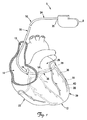
図1は、本発明の一実施形態による、患者の心臓12内に展開され固定されたリード線10に結合されたパルス発生器8を含む心調律管理システム5の概略図である。図示されるように、心臓12は、上大静脈13、右心房14および右心室23、左心房26および左心室28、右心房14内の冠状静脈洞孔16、冠状静脈洞18、ならびに、大心静脈29を含む種々の心臓血管および例示的な分枝血管30を含む冠状静脈洞18からの他の分枝血管を含む。
FIG. 1 is a schematic diagram of a cardiac rhythm management system 5 that includes a
示される実施形態では、リード線10は、電気絶縁性材料から形成されており、かつ、近位端35を含む近位部分34および遠位端38を含む遠位部分36を有する長尺状のリード線本体32を含む。遠位部分36は、少なくとも1つの電極40を含む。図示されるように、近位端35は、パルス発生器8に機械的にかつ電気的に接続され、遠位部分36は、上大静脈13、右心房14および冠状静脈洞18を通って分枝血管30内に延伸し、遠位端38、また従って電極40は分枝血管30内に配置される。示されるリード線10の位置は、たとえば、生理的パラメータを検知し、心臓12の左側にペーシングおよび/またはデフィブリレーション刺激を送達するために使用されてもよい。他の実施形態では、リード線10はまた、心臓12の左側(または他の部分)に治療を提供するために、大心静脈29などの他の冠状静脈または他の分枝血管内で展開してもよい。
In the embodiment shown, the
さらに、リード線10は、遠位部分36において、リード線本体32上に位置する膨張可能部材55の形態の固着構造を含む。以下で詳細に説明されるように、膨張可能部材55は、収縮状態および膨張状態を取るように操作可能であり、膨張状態は、遠位端38、特に、電極40を所望の埋め込み位置に緊急にかつ/または長期的に固定するときに使用するためのものである。示される実施形態では、膨張可能部材55は、リード線本体32の周りに完全に円周方向に延在する。以下に示され、かつ説明されるように、他の実施形態では、膨張可能な固着部材はリード線本体の周りに少なくとも部分的に延在してもよく、かつ/または、代替の形状を有していてもよい。種々の実施形態では、複数の膨張可能部材が、リード線本体32の長さ方向に沿って所定の位置に設けられてもよい。
Further, the
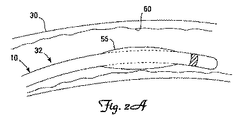
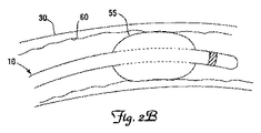
図2Aおよび2Bは、本発明の例示的な実施形態による分枝血管30内に配置されたリード線10の遠位部分36の概略図である。図示されるように、膨張可能部材55は、リード線10を所望の埋め込み位置に送達するために収縮状態(図2A)を取ることができる。収縮状態では、膨張可能部材55は、リード線10の経静脈的送達をそれほど妨害しまたは遅延させないように、リード線本体32の外径をそれほど増加させない。膨張可能部材55は、配置されると、膨張して半径方向に拡張し、冠状分枝静脈30の内側表面に半径方向力を与えることができる。膨張可能部材55は、所望される場合、臨床医のニーズに応じて、固着力を取除くためにその後収縮されてもよい。たとえば、一部の実施形態では、リード線10の最初の展開後に、同じまたは異なる冠状静脈内に再配置されるべきであると臨床医が判断する場合がある。あるいは、膨張可能部材55の収縮は、患者からリード線10の除去を容易にするために行われてもよい。一部の実施形態では、膨張可能部材55は、たとえば患者からのガイドワイヤまたはガイドカテーテルの引抜き中に一時的な固着力および安定化力を提供するためだけのリード線の送達に使用されてもよい。さらに、固着の程度(すなわち、膨張可能部材55によって内側表面60に与えられる半径方向力の大きさ)は、膨張可能部材55の膨張圧を増加させるかまたは減少させることによって調整可能である。こうして、膨張可能部材55は、有利には、臨床医の所望の通りに起動および停止可能な展開可能固着手段を提供する。
2A and 2B are schematic views of the
図2Aおよび2Bに示される実施形態では、膨張可能部材55は、遠位端38および電極40の近く、したがって標的分枝血管30内に埋め込まれるリード線10の部分内に示されるが、他の実施形態では、膨張可能部材55は、遠位部分36上の任意の位置に配置されてもよい。すなわち、膨張可能部材55は、リード線10が埋め込まれたとき、冠状静脈洞18または分枝血管30内に存在し得るリード線本体32の任意の位置に位置付けられてもよい。
In the embodiment shown in FIGS. 2A and 2B, the
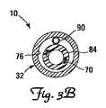
図3Aは、本発明の一実施形態によるリード線10の側断面図であり、図3Bは、リード線10の端断面図である。図示されるように、リード線10は近位端35から遠位端38に向かって延在する導電性部材70を含み、リード線本体32は内側表面76を含む。示される実施形態では、導電性部材70は絶縁性ワイヤコイルの形態である。そのため、図3Aに見られるように、リード線本体32は外側絶縁層80を提供し、導電性部材絶縁体は内側表面76から分離された内側絶縁層84を形成する。リード線10は、さらに内側絶縁層84と内側表面76との間の膨張管腔90を含む。図示されるように、膨張管腔90は、膨張可能部材55に連通する長尺状の管状部材の形態であり、適切な生体適合性膨張媒体を使用して膨張可能部材55の膨張を容易にするように働く。
3A is a side sectional view of the
示される実施形態では、巻回式導電性部材70は、オーバー・ザ・ワイヤ(over the wire)送達手段で使用されるスタイレットまたはガイドワイヤを受容することによってリード線送達を容易にし得る主リード線管腔94を形成する。別の実施形態では、リード線10は、非巻回式導電性部材70(すなわちケーブル)を含んでもよい。こうした実施形態では、別個の管腔が、リード線送達または臨床医によって適切であると考えられる他の用途のために設けられてもよい。種々の実施形態では、他の管腔は、臨床医によって所望される任意の用途のために設けられてもよい。一部の実施形態では、リード線10は、多電極リード線として知られているような複数の導電性部材を含んでもよい。
In the embodiment shown, the wound
さらに示されるように、膨張管腔90は、近位端35に近接するリード線本体32を貫通して延在するポータル100に結合し、さらに、リード線本体32内のオリフィス106を通って延在して、ポータル100と膨張可能部材55とを流体結合する。そのため、膨張可能部材55を、膨張可能部材55の所望の程度の膨張が達成されるまで、ポータル100を通して流体を導入することによって膨張させることができる。
As further shown, the
流体または他の膨張媒体を、シリンジ、インデフレータまたは当技術分野で知られている他の適切な導入手段を使用して、ポータル100を通して膨張管腔90内に導入することができる。ポータル100は、シリンジ、インデフレータまたは他の導入手段の導入を可能にし、さらに、膨張可能部材55の膨張後の、ポータル100を介した流体の損失を実質的に防止するように適合されている密封構造(たとえば、止血弁シールなどのシール)を含んでもよい。別の実施形態では、ポータル100は、圧着または閉栓されてポータル100が密封され、ポータル100を介した膨張流体の損失が防止されてもよい。別の例示的な実施形態では、ポータル100は、膨張管腔90および膨張可能部材55内に膨張流体を保持するために自己密封性である。たとえば、ポータル100は、シリコーンプラグを含んでもよい。一般に知られているように、シリコーンは、貫通されると自然に自己密封する傾向がある。ポータル100を密封する他の技法および構造は、上記に基づいて当業者によって理解されるであろう。
A fluid or other inflation medium can be introduced into the
図4Aは、本発明の別の実施形態によるリード線210の側断面図であり、図4Bは、リード線210の端断面図である。リード線210は、全体がリード線10と同じであり、近位端235および遠位端238を有する電気絶縁性材料から形成されたリード線本体232ならびにリード線本体232上の膨張可能部材255を含む。図示されるように、リード線210は、近位端235から遠位端238に向かって延在する導電性部材270を含み、リード線本体232は、内側表面276を含む。リード線210は、さらに、導電性部材270とリード線本体232の内側表面276との間に配設された導電性材料、たとえばポリウレタンから形成された、ほぼ管状かつ可撓性の内側絶縁シース278を含む。したがって、図4Aに見られるように、リード線本体232は外側絶縁層280を提供し、内側絶縁シース278は、内側表面276から分離された内側絶縁層を形成して、膨張可能部材255に連通する膨張管腔290を画定する。別の実施形態では、巻回式導電性部材290を覆う電気絶縁性コーティングが内側絶縁層を形成する。リード線10の膨張管腔90のように、環状膨張管腔290は、膨張可能部材255を膨張させるための流体の導入を容易にするように構成される。
FIG. 4A is a side cross-sectional view of a
さらに図示されるように、リード線210は、さらに近位端235に近接するリード線本体232を貫通して延在するポータル300、および膨張可能部材255と膨張管腔290とを流体結合するための、リード線本体32を貫通して延在するオリフィス306を含む。リード線10の場合と同様に、流体または他の膨張媒体は、シリンジ、インデフレータまたは当技術分野で知られている他の適切な導入手段を使用して、リード線10に関して上述したものと同様の密封構造を含み得るポータル300を通して、環状膨張管腔290内に導入されることができる。
As further illustrated, the
図4Bに示されるように、一部の実施形態では、リード線210は内側絶縁シース278とリード線本体232の内側表面276との間に配設されて両者の間の分離を維持し、それにより膨張管腔290を維持する1つまたは複数の任意のスペーサ部材310を含んでもよい。他の実施形態では、リード線210は、複数のスペーサ部材310を含んでもよい。一実施形態では、円周方向に離間した長尺状のリブ(図示せず)が、リード線本体232の内側表面276または内側絶縁シース278に沿って長手方向に延在するように設けられてもよく、リブはこれらの構造体を分離し、膨張管腔290として働くチャネル(すなわち、隣接するリブ間の空間)を提供するように働いてもよい。内側絶縁シース278とリード線本体の内側表面276との間の分離を維持する他の構造および技法は、上記に基づいて当業者に明らかになるであろう。
As shown in FIG. 4B, in some embodiments, the
上述した膨張可能部材55、255は、所望の継続時間にわたって固着安定性を提供するのに十分なフープ強度と破裂圧力を維持することができ、かつ、比較的スムーズなそれぞれのリード線の送達を容易にするのに十分な柔軟性を有する任意の生体適合性または生体吸収性材料から作られてもよい。種々の実施形態では、膨張可能部材55および/または255は、実質的にまたは完全に、シリコーンゴム、ポリウレタンまたはポリエーテルブロックアミドから形成されてもよい。一実施形態では、膨張可能部材は、リード線本体の外側表面に粘着結合したシリコーンゴム膜である。
The
代替の実施形態では、膨張可能部材は、膨張可能部材の経時的な収縮を可能にするために、膨張媒体の制御された放出を可能にするよう選択された半多孔質材料から形成されてもよい。たとえば、1つのこうした実施形態では、膨張可能部材が、制限された継続時間の間だけ、たとえば、組織内部成長および線維症が主要な固着構造として取って代わるまで、固着力を供給することが望ましい場合がある。こうした場合、膨張可能部材は、血流内への膨張媒体の拡散を可能にするよう構成された半多孔質材料から形成され得るため、膨張可能部材は、たとえば、2〜4週後には固着力をもはや提供しない。なお別の実施形態では、当技術分野で知られるように、生体吸収性材料から膨張可能部材を形成することによって類似の結果が達成され得る。 In an alternative embodiment, the inflatable member may be formed from a semi-porous material selected to allow controlled release of the inflation medium to allow shrinkage of the inflatable member over time. Good. For example, in one such embodiment, it is desirable for the expandable member to provide an anchoring force only for a limited duration, eg, until tissue ingrowth and fibrosis have replaced the primary anchoring structure. There is a case. In such cases, the inflatable member may be formed from a semi-porous material configured to allow diffusion of the inflation medium into the bloodstream, so that the inflatable member may have an adhesive force, for example, after 2-4 weeks No longer provide. In yet another embodiment, similar results can be achieved by forming an inflatable member from a bioabsorbable material, as is known in the art.
絶縁材料(たとえば、それぞれリード線10、210の本体32、232)は、現在知られているか、後に開発されるかにかかわらず、経静脈的に展開される心臓リード線に適した任意の電気絶縁性材料から形成され得る。一実施形態では、リード線本体32、232および内側絶縁層(すなわち、内側絶縁層84および絶縁シース276)は、実質的にポリウレタンから形成される。
Insulating material (eg,
上述した膨張可能部材55、255は、左心室刺激で使用する大きさおよび形状の任意の医療用電気リード線内に組込まれてもよい。リード線10、210の管腔設計は、膨張管腔(複数可)がリード線本体の外側絶縁層の厚さ内に配設された膨張可能バルーン構造を有する従来のリード線と比較して、径の小さいリード線サイズ内への膨張可能部材55、255の組込みを容易にし得る。すなわち、膨張管腔をリード線本体外側層の厚さ内に配設することは、その層の全体の厚さの増加を必要とする場合があり、結果としてリード線の径は比較的大きくなる。さらに、膨張管腔を収容するために外側層の厚さを増加させることは、リード線の全体の剛性を増加させる可能性があり、リード線の経静脈的送達に悪影響を及ぼす可能性がある。簡潔に言えば、本発明のリード線10、210の膨張管腔構成は、おそらくは曲がりくねった静脈の解剖学的構造を通して送達されなければならない左側リード線にとって好適であり得る。
The
本明細書で説明される膨張可能部材55、255は、空気、生理食塩水あるいは任意の他の生体適合性ガスまたは液体媒体を含むがこれらに限定されない任意の生体適合性流体を使用して膨張させてもよい。
The
図5Aおよび5Bは、それぞれ本発明のさらなる実施形態によるリード線410、412の一部分を示す。リード線410、412は多くの点で上述したリード線に実質的に同じか、または同一であってもよく、例外は膨張可能部材構成にある。図5Aに示されるように、リード線410は、リード線本体の周りに部分的にのみ延在する膨張可能部材455を含む。たとえば一実施形態では、膨張可能部材455はリード線本体の周りに約90°から約270°の範囲で延在する。示される構成により、膨張可能部材455は膨張すると、リード線410の遠位端が埋め込まれる標的分岐血管30の内側表面60に対し、有利にリード線電極を偏在させることができる。したがって、膨張可能部材455は、リード線410を所定位置に固定し、また、血管組織との電極接触を改善するように働く。図5Bに示されるように、リード線412は、リード線本体の周りにほぼ螺旋状にで配設される膨張可能部材455を含む。他の膨張可能部材の形状および構成が、本発明の範囲内で利用され得ることが理解されるであろう。
5A and 5B each show a portion of a
上記で説明された実施形態では、それぞれのリード線は、単一の膨張可能な固着部材、たとえば、膨張可能部材55、255および455を含む。他の実施形態では、複数の膨張可能部材が設けられる。たとえば、一実施形態では、膨張可能部材が、リード線遠位端が埋め込まれる標的分枝血管内に配置されるように、リード線は、リード線本体に沿って位置する2つ以上の膨張可能部材を含んでもよい。他の実施形態では、リード線は、1つの膨張可能部材を、それを標的分枝血管内に配置することができるような位置に含み、かつ、冠状静脈洞18内に配置される別の膨張可能部材を含んでもよい(図1を参照されたい)。こうした実施形態では、冠状静脈洞18内に配置される膨張可能部材は、埋め込み処置の最中に(たとえば、周知のような、オーバー・ザ・ワイヤ埋め込みにおけるガイドワイヤの引抜き中に)向上した安定性および固着力を提供し得る。膨張可能な固着部材の他の組合せは、上記に基づいて当業者によって理解されるであろう。
In the embodiments described above, each lead includes a single inflatable anchor member, such as
本発明の範囲から逸脱することなく説明される例示的な実施形態に対して、種々の変更および追加がなされ得る。たとえば、上述した実施形態は特定の特徴に言及しているが、本発明の範囲はまた、特徴の異なる組合せを有する実施形態および説明された特徴の全てを含むわけではない実施形態も含む。したがって、本発明の範囲は、全てのこうした代替例、変更例および変形例を、それらの全ての均等物と共に、特許請求の範囲に含むものとして包含するように意図されている。 Various changes and additions can be made to the exemplary embodiments described without departing from the scope of the present invention. For example, although the embodiments described above refer to particular features, the scope of the invention also includes embodiments having different combinations of features and embodiments that do not include all of the described features. Accordingly, the scope of the present invention is intended to embrace all such alternatives, modifications and variations as if included in the claims, along with all their equivalents.
Claims (20)
前記近位端と前記遠位端との間で前記本体の外側表面上に配設された膨張可能部材であって、収縮状態および膨張状態を取るように適合されており、膨張状態において、前記冠状静脈洞または冠状静脈の表面に半径方向力を与えて摩擦係合し、その位置に前記遠位端を固着するように適合された膨張可能部材と、
前記本体の少なくとも前記近位端から前記遠位端へ向かって延在する導電性部材と、
前記導電性部材と前記本体の内側表面との間に配設され、かつ、前記近位端から前記遠位端へ向かって延在する内側絶縁層と、
前記膨張可能部材に連通する、前記内側絶縁層と前記本体の内側表面との間の膨張管腔と、
前記導電性部材に電気的に接続された前記本体上の電極とを備える医療用電気リード線。 A proximal end, a distal end, an outer surface and an inner surface, and the body is made of an electrically insulating material, and the distal end is dimensioned to be implantable in a coronary sinus or coronary vein A long lead wire body;
An inflatable member disposed on an outer surface of the body between the proximal end and the distal end, wherein the inflatable member is adapted to assume a contracted state and an expanded state; An inflatable member adapted to apply a radial force to the coronary sinus or coronary vein surface to frictionally engage and secure the distal end in position;
A conductive member extending from at least the proximal end of the body toward the distal end;
An inner insulating layer disposed between the conductive member and the inner surface of the body and extending from the proximal end toward the distal end;
An inflation lumen between the inner insulating layer and the inner surface of the body in communication with the inflatable member;
A medical electrical lead comprising: an electrode on the body electrically connected to the conductive member.
前記近位端と前記遠位端との間の前記本体の外側表面上に配設された膨張可能部材であって、収縮状態および膨張状態を取るように適合されており、膨張状態において、前記冠状静脈洞または冠状静脈の表面に半径方向力を与えて摩擦係合し、その位置に前記遠位端を固着するように適合された膨張可能部材と、
前記本体の少なくとも前記近位端から前記遠位端へ向かって延在する導電性部材であって、絶縁性コーティングを含み、前記絶縁性コーティングと前記本体の内側表面との間の分離が前記膨張可能部材に連通する膨張管腔を画定する導電性部材と、
前記導電性部材に電気的に接続された前記本体上の電極とを備える医療用電気リード線。 A long end having a proximal end, a distal end, an outer surface and an inner surface and made of an electrically insulative material and dimensioned to allow the distal end to be implanted in a coronary sinus or coronary vein Lead wire body,
An inflatable member disposed on an outer surface of the body between the proximal end and the distal end, wherein the inflatable member is adapted to assume a contracted state and an expanded state; An inflatable member adapted to apply a radial force to the coronary sinus or coronary vein surface to frictionally engage and secure the distal end in position;
A conductive member extending from at least the proximal end to the distal end of the body, comprising an insulating coating, wherein the separation between the insulating coating and the inner surface of the body is the expansion A conductive member defining an inflation lumen in communication with the possible member;
A medical electrical lead comprising: an electrode on the body electrically connected to the conductive member.
前記近位端と前記遠位端との間の前記本体の外側表面上に配設された膨張可能部材であって、収縮状態および膨張状態を取るように適合されており、膨張状態において、膨張可能部材が、前記冠状静脈洞または冠状静脈の表面に半径方向力を与えて摩擦係合し、その位置に前記遠位端を固着するように適合された膨張可能部材と、
前記本体の少なくとも前記近位端から前記遠位端へ向かって延在する導電性部材と、
前記導電性部材と前記本体の内側表面との間に配設される電気絶縁性材料から形成されたほぼ管状の可撓性シースであって、前記シースと前記本体の内側表面との間の分離が前記膨張可能部材に連通する膨張管腔を画定しているシースと、
前記導電性部材に電気的に接続された前記本体上の電極とを備える医療用電気リード線。 A long end having a proximal end, a distal end, an outer surface and an inner surface and made of an electrically insulative material and dimensioned to allow the distal end to be implanted in a coronary sinus or coronary vein Lead wire body,
An inflatable member disposed on the outer surface of the body between the proximal end and the distal end, the inflatable member being adapted to assume a contracted state and an expanded state, An inflatable member adapted to apply a radial force to the coronary sinus or coronary vein surface to frictionally engage and secure the distal end in position;
A conductive member extending from at least the proximal end of the body toward the distal end;
A substantially tubular flexible sheath formed from an electrically insulating material disposed between the conductive member and an inner surface of the body, the separation between the sheath and the inner surface of the body A sheath defining an inflation lumen in communication with the inflatable member;
A medical electrical lead comprising: an electrode on the body electrically connected to the conductive member.
Applications Claiming Priority (2)
| Application Number | Priority Date | Filing Date | Title |
|---|---|---|---|
| US11/622,810 US7765015B2 (en) | 2007-01-12 | 2007-01-12 | Lead with inflatable fixation mechanism |
| PCT/US2008/050455 WO2008088967A1 (en) | 2007-01-12 | 2008-01-08 | Lead with inflatable fixation mechanism |
Publications (2)
| Publication Number | Publication Date |
|---|---|
| JP2010515537A true JP2010515537A (en) | 2010-05-13 |
| JP2010515537A5 JP2010515537A5 (en) | 2011-03-03 |
Family
ID=39301181
Family Applications (1)
| Application Number | Title | Priority Date | Filing Date |
|---|---|---|---|
| JP2009545629A Pending JP2010515537A (en) | 2007-01-12 | 2008-01-08 | Lead wire having an expandable fixing structure |
Country Status (4)
| Country | Link |
|---|---|
| US (1) | US7765015B2 (en) |
| EP (1) | EP2117637B1 (en) |
| JP (1) | JP2010515537A (en) |
| WO (1) | WO2008088967A1 (en) |
Cited By (1)
| Publication number | Priority date | Publication date | Assignee | Title |
|---|---|---|---|---|
| JP2016179200A (en) * | 2010-09-28 | 2016-10-13 | ザ ボード オブ トラスティーズ オブ ザ リーランド スタンフォード ジュニア ユニバーシティ | Device and method for positioning electrode in tissue |
Families Citing this family (31)
| Publication number | Priority date | Publication date | Assignee | Title |
|---|---|---|---|---|
| US8406901B2 (en) * | 2006-04-27 | 2013-03-26 | Medtronic, Inc. | Sutureless implantable medical device fixation |
| US9492657B2 (en) * | 2006-11-30 | 2016-11-15 | Medtronic, Inc. | Method of implanting a medical device including a fixation element |
| US8343029B2 (en) * | 2007-10-24 | 2013-01-01 | Circulite, Inc. | Transseptal cannula, tip, delivery system, and method |
| US8460168B2 (en) | 2009-03-27 | 2013-06-11 | Circulite, Inc. | Transseptal cannula device, coaxial balloon delivery device, and methods of using the same |
| US8478423B2 (en) * | 2009-04-07 | 2013-07-02 | Boston Scientific Neuromodulation Corporation | Insulator layers for leads of implantable electric stimulation systems and methods of making and using |
| CA2768567C (en) | 2009-09-14 | 2017-03-21 | Circulite, Inc. | Endovascular anastomotic connector device, delivery system, and methods of delivery and use |
| US9872981B2 (en) | 2010-09-28 | 2018-01-23 | Biotrace Medical, Inc. | Device and method for positioning an electrode in a body cavity |
| US10112045B2 (en) | 2010-12-29 | 2018-10-30 | Medtronic, Inc. | Implantable medical device fixation |
| US9775982B2 (en) | 2010-12-29 | 2017-10-03 | Medtronic, Inc. | Implantable medical device fixation |
| US10434292B2 (en) * | 2011-06-24 | 2019-10-08 | Access Closure | Method and devices for flow occlusion during device exchanges |
| WO2012178073A1 (en) * | 2011-06-24 | 2012-12-27 | Accessclosure, Inc. | Method and devices for flow occlusion during device exchanges |
| US20130158640A1 (en) * | 2011-12-19 | 2013-06-20 | Brian D. Soltis | Lead anchoring system with limited movement of anchoring device along lead |
| US10485435B2 (en) | 2012-03-26 | 2019-11-26 | Medtronic, Inc. | Pass-through implantable medical device delivery catheter with removeable distal tip |
| US9833625B2 (en) | 2012-03-26 | 2017-12-05 | Medtronic, Inc. | Implantable medical device delivery with inner and outer sheaths |
| US9717421B2 (en) | 2012-03-26 | 2017-08-01 | Medtronic, Inc. | Implantable medical device delivery catheter with tether |
| US9339197B2 (en) | 2012-03-26 | 2016-05-17 | Medtronic, Inc. | Intravascular implantable medical device introduction |
| US9220906B2 (en) | 2012-03-26 | 2015-12-29 | Medtronic, Inc. | Tethered implantable medical device deployment |
| US9854982B2 (en) | 2012-03-26 | 2018-01-02 | Medtronic, Inc. | Implantable medical device deployment within a vessel |
| US9532785B2 (en) | 2012-05-09 | 2017-01-03 | Access Closure, Inc. | Method and devices for flow occlusion during device exchanges |
| US9351648B2 (en) | 2012-08-24 | 2016-05-31 | Medtronic, Inc. | Implantable medical device electrode assembly |
| JP6085682B2 (en) | 2012-10-29 | 2017-02-22 | カーディアック ペースメイカーズ, インコーポレイテッド | Suture sleeve having an outer surface with fracture resistance |
| US9486622B2 (en) | 2012-11-08 | 2016-11-08 | Cardiac Pacemakers, Inc. | Fixation and strain relief element for temporary therapy delivery device |
| ES2765303T3 (en) * | 2013-11-25 | 2020-06-08 | Custom Medical Applications Inc | Anchor Element Deployment Assembly for Medical Devices |
| WO2015172023A2 (en) | 2014-05-09 | 2015-11-12 | Biotrace Medical, Inc. | Device and method for positioning an electrode in a body cavity |
| US10286208B2 (en) | 2015-05-20 | 2019-05-14 | Cardiac Pacemakers, Inc. | Fully integrated lead stabilizer for medical electrical leads and methods of attachment |
| WO2017048992A1 (en) | 2015-09-15 | 2017-03-23 | Racz N Sandor | Deployment devices and related assemblies and methods |
| CN108348756B (en) | 2015-11-20 | 2021-10-22 | 心脏起搏器股份公司 | Single channel coronary vein lead for multi-chamber sensing and pacing |
| CN109476815B (en) | 2016-07-28 | 2021-05-04 | 3M创新有限公司 | Segmented silicone polyamide block copolymers and articles comprising the same |
| JP6837126B6 (en) | 2016-07-28 | 2021-03-31 | スリーエム イノベイティブ プロパティズ カンパニー | Segmented Silicon Polyamide Block Copolymer and Articles Containing It |
| US10874850B2 (en) | 2018-09-28 | 2020-12-29 | Medtronic, Inc. | Impedance-based verification for delivery of implantable medical devices |
| US11331475B2 (en) | 2019-05-07 | 2022-05-17 | Medtronic, Inc. | Tether assemblies for medical device delivery systems |
Citations (3)
| Publication number | Priority date | Publication date | Assignee | Title |
|---|---|---|---|---|
| US5282785A (en) * | 1990-06-15 | 1994-02-01 | Cortrak Medical, Inc. | Drug delivery apparatus and method |
| JP2002503986A (en) * | 1997-06-03 | 2002-02-05 | ボストン サイエンティフィック リミテッド | Perfusion balloon and radioactive wire delivery system |
| US20020077685A1 (en) * | 2000-12-20 | 2002-06-20 | Medtronic, Inc. | Medical electrical lead and method of use |
Family Cites Families (30)
| Publication number | Priority date | Publication date | Assignee | Title |
|---|---|---|---|---|
| DE2305262A1 (en) * | 1973-02-02 | 1974-08-08 | Siemens Ag | ENDOCARD ELECTRODE |
| US4559951A (en) * | 1982-11-29 | 1985-12-24 | Cardiac Pacemakers, Inc. | Catheter assembly |
| US4519403A (en) * | 1983-04-29 | 1985-05-28 | Medtronic, Inc. | Balloon lead and inflator |
| US4531943A (en) * | 1983-08-08 | 1985-07-30 | Angiomedics Corporation | Catheter with soft deformable tip |
| US4551292A (en) * | 1984-04-05 | 1985-11-05 | Angiomedics, Inc. | Method for making a catheter with a soft, deformable tip |
| US4706682A (en) * | 1985-08-21 | 1987-11-17 | Minnesota Mining And Manufacturing Company | External ear canal electrode to be placed proximate the tympanic membrane |
| US4863442A (en) * | 1987-08-14 | 1989-09-05 | C. R. Bard, Inc. | Soft tip catheter |
| US5025786A (en) * | 1988-07-21 | 1991-06-25 | Siegel Sharon B | Intracardiac catheter and method for detecting and diagnosing myocardial ischemia |
| US5087244A (en) * | 1989-01-31 | 1992-02-11 | C. R. Bard, Inc. | Catheter and method for locally applying medication to the wall of a blood vessel or other body lumen |
| US5205292A (en) * | 1991-06-03 | 1993-04-27 | Applied Biometric, Inc. | Removable implanted device |
| US5571159A (en) * | 1994-04-04 | 1996-11-05 | Alt; Eckhard | Temporary atrial defibrillation catheter and method |
| US6108706A (en) * | 1997-06-09 | 2000-08-22 | Microsoft Corporation | Transmission announcement system and method for announcing upcoming data transmissions over a broadcast network |
| US5991668A (en) * | 1997-09-25 | 1999-11-23 | Medtronic, Inc. | Medical electrical lead |
| US5925073A (en) * | 1998-02-23 | 1999-07-20 | Cardiac Pacemakers, Inc. | Intravenous cardiac lead with wave shaped fixation segment |
| US5951597A (en) * | 1998-04-14 | 1999-09-14 | Cardiac Pacemakers, Inc. | Coronary sinus lead having expandable matrix anchor |
| SE9802104D0 (en) * | 1998-06-12 | 1998-06-12 | Pacesetter Ab | Medical electrode device |
| FR2784300B1 (en) * | 1998-10-13 | 2000-12-08 | Ela Medical Sa | IMPLANTABLE LEFT VENTRICLE STIMULATION PROBE IN THE CORONARY VENOUS NETWORK FOR ACTIVE IMPLANTABLE MEDICAL DEVICE, IN PARTICULAR "MULTI-SITE" STIMULATOR |
| US7313444B2 (en) * | 1998-11-20 | 2007-12-25 | Pacesetter, Inc. | Self-anchoring coronary sinus lead |
| US6136021A (en) * | 1999-03-23 | 2000-10-24 | Cardiac Pacemakers, Inc. | Expandable electrode for coronary venous leads |
| CA2376903A1 (en) * | 1999-06-25 | 2001-01-04 | Emory University | Devices and methods for vagus nerve stimulation |
| US6556873B1 (en) * | 1999-11-29 | 2003-04-29 | Medtronic, Inc. | Medical electrical lead having variable bending stiffness |
| US6510348B2 (en) * | 2000-12-20 | 2003-01-21 | Medtronic, Inc. | Perfusion lead and method of use |
| US7099718B1 (en) * | 2001-05-29 | 2006-08-29 | Advanced Bionics Corporation | Neural stimulation lead fixation |
| US6968237B2 (en) * | 2002-05-22 | 2005-11-22 | Pacesetter, Inc. | Implantable coronary sinus lead and lead system |
| US7107105B2 (en) | 2002-09-24 | 2006-09-12 | Medtronic, Inc. | Deployable medical lead fixation system and method |
| US7228356B2 (en) * | 2002-12-12 | 2007-06-05 | Alcatel Canada Inc. | IGMP expedited leave triggered by MAC address |
| US20040230282A1 (en) * | 2003-04-11 | 2004-11-18 | Cates Adam W. | Acute and chronic fixation for subcutaneous electrodes |
| US20040243210A1 (en) * | 2003-05-30 | 2004-12-02 | Morgan Kevin L. | Fixation of a left heart medical lead in the coronary sinus |
| EP1682215B1 (en) * | 2003-10-24 | 2008-12-24 | Cardiac Pacemakers, Inc. | Myocardial lead attachment system |
| US20060089694A1 (en) * | 2004-10-21 | 2006-04-27 | Cardiac Pacemakers, Inc. | Delivery system and method for pulmonary artery leads |
-
2007
- 2007-01-12 US US11/622,810 patent/US7765015B2/en not_active Expired - Fee Related
-
2008
- 2008-01-08 WO PCT/US2008/050455 patent/WO2008088967A1/en active Application Filing
- 2008-01-08 EP EP08705760.0A patent/EP2117637B1/en not_active Not-in-force
- 2008-01-08 JP JP2009545629A patent/JP2010515537A/en active Pending
Patent Citations (3)
| Publication number | Priority date | Publication date | Assignee | Title |
|---|---|---|---|---|
| US5282785A (en) * | 1990-06-15 | 1994-02-01 | Cortrak Medical, Inc. | Drug delivery apparatus and method |
| JP2002503986A (en) * | 1997-06-03 | 2002-02-05 | ボストン サイエンティフィック リミテッド | Perfusion balloon and radioactive wire delivery system |
| US20020077685A1 (en) * | 2000-12-20 | 2002-06-20 | Medtronic, Inc. | Medical electrical lead and method of use |
Cited By (1)
| Publication number | Priority date | Publication date | Assignee | Title |
|---|---|---|---|---|
| JP2016179200A (en) * | 2010-09-28 | 2016-10-13 | ザ ボード オブ トラスティーズ オブ ザ リーランド スタンフォード ジュニア ユニバーシティ | Device and method for positioning electrode in tissue |
Also Published As
| Publication number | Publication date |
|---|---|
| US20080172118A1 (en) | 2008-07-17 |
| WO2008088967A1 (en) | 2008-07-24 |
| EP2117637A1 (en) | 2009-11-18 |
| EP2117637B1 (en) | 2017-03-01 |
| US7765015B2 (en) | 2010-07-27 |
Similar Documents
| Publication | Publication Date | Title |
|---|---|---|
| JP2010515537A (en) | Lead wire having an expandable fixing structure | |
| US10980570B2 (en) | Implantation of an active medical device using the internal thoracic vasculature | |
| US10537731B2 (en) | Transvenous mediastinum access for the placement of cardiac pacing and defibrillation electrodes | |
| US10786679B2 (en) | Lead with integrated electrodes | |
| US6240322B1 (en) | System and apparatus having low profile collapsible tines | |
| US20180133463A1 (en) | Electrode for sensing, pacing, and defibrillation deployable in the mediastinal space | |
| US9039594B2 (en) | Signal transmitting and lesion excluding heart implants for pacing, defibrillating, and/or sensing of heart beat | |
| US6909920B2 (en) | System and method for positioning an implantable medical device within a body | |
| US8442656B2 (en) | Cardiac lead having implantable stiffening structures for fixation | |
| EP1056507B1 (en) | Intravenous cardiac lead with positive fixation segment | |
| US6567704B2 (en) | Medical electrical lead and method of use | |
| US20060089694A1 (en) | Delivery system and method for pulmonary artery leads | |
| US7529589B2 (en) | Intravascular electrophysiological system and methods | |
| CN102711902B (en) | Seal wire type pacing lead | |
| US11020075B2 (en) | Implantation of an active medical device using the internal thoracic vasculature | |
| EP2024015B1 (en) | Cardiac lead having stiffening structures for fixation | |
| US20070293923A1 (en) | Lead with orientation feature | |
| EP0959940B1 (en) | Lead introducer with defibrillation electrode for atrial defibrillation | |
| US7308319B2 (en) | Delivery system and method using pulmonary artery for placement of RV leads |
Legal Events
| Date | Code | Title | Description |
|---|---|---|---|
| A521 | Written amendment |
Free format text: JAPANESE INTERMEDIATE CODE: A523 Effective date: 20110106 |
|
| A621 | Written request for application examination |
Free format text: JAPANESE INTERMEDIATE CODE: A621 Effective date: 20110106 |
|
| RD04 | Notification of resignation of power of attorney |
Free format text: JAPANESE INTERMEDIATE CODE: A7424 Effective date: 20120229 |
|
| A131 | Notification of reasons for refusal |
Free format text: JAPANESE INTERMEDIATE CODE: A131 Effective date: 20121023 |
|
| A977 | Report on retrieval |
Free format text: JAPANESE INTERMEDIATE CODE: A971007 Effective date: 20121025 |
|
| A02 | Decision of refusal |
Free format text: JAPANESE INTERMEDIATE CODE: A02 Effective date: 20130319 |