JP2010515216A - End cap seal assembly for electrochemical cells - Google Patents
End cap seal assembly for electrochemical cells Download PDFInfo
- Publication number
- JP2010515216A JP2010515216A JP2009543570A JP2009543570A JP2010515216A JP 2010515216 A JP2010515216 A JP 2010515216A JP 2009543570 A JP2009543570 A JP 2009543570A JP 2009543570 A JP2009543570 A JP 2009543570A JP 2010515216 A JP2010515216 A JP 2010515216A
- Authority
- JP
- Japan
- Prior art keywords
- disk
- battery
- end cap
- support disk
- metal support
- Prior art date
- Legal status (The legal status is an assumption and is not a legal conclusion. Google has not performed a legal analysis and makes no representation as to the accuracy of the status listed.)
- Withdrawn
Links
Images


Classifications
-
- H—ELECTRICITY
- H01—ELECTRIC ELEMENTS
- H01M—PROCESSES OR MEANS, e.g. BATTERIES, FOR THE DIRECT CONVERSION OF CHEMICAL ENERGY INTO ELECTRICAL ENERGY
- H01M50/00—Constructional details or processes of manufacture of the non-active parts of electrochemical cells other than fuel cells, e.g. hybrid cells
- H01M50/10—Primary casings, jackets or wrappings of a single cell or a single battery
- H01M50/147—Lids or covers
- H01M50/166—Lids or covers characterised by the methods of assembling casings with lids
- H01M50/171—Lids or covers characterised by the methods of assembling casings with lids using adhesives or sealing agents
-
- H—ELECTRICITY
- H01—ELECTRIC ELEMENTS
- H01M—PROCESSES OR MEANS, e.g. BATTERIES, FOR THE DIRECT CONVERSION OF CHEMICAL ENERGY INTO ELECTRICAL ENERGY
- H01M50/00—Constructional details or processes of manufacture of the non-active parts of electrochemical cells other than fuel cells, e.g. hybrid cells
- H01M50/30—Arrangements for facilitating escape of gases
- H01M50/342—Non-re-sealable arrangements
- H01M50/3425—Non-re-sealable arrangements in the form of rupturable membranes or weakened parts, e.g. pierced with the aid of a sharp member
-
- H—ELECTRICITY
- H01—ELECTRIC ELEMENTS
- H01M—PROCESSES OR MEANS, e.g. BATTERIES, FOR THE DIRECT CONVERSION OF CHEMICAL ENERGY INTO ELECTRICAL ENERGY
- H01M50/00—Constructional details or processes of manufacture of the non-active parts of electrochemical cells other than fuel cells, e.g. hybrid cells
- H01M50/10—Primary casings, jackets or wrappings of a single cell or a single battery
- H01M50/116—Primary casings, jackets or wrappings of a single cell or a single battery characterised by the material
- H01M50/117—Inorganic material
- H01M50/119—Metals
-
- H—ELECTRICITY
- H01—ELECTRIC ELEMENTS
- H01M—PROCESSES OR MEANS, e.g. BATTERIES, FOR THE DIRECT CONVERSION OF CHEMICAL ENERGY INTO ELECTRICAL ENERGY
- H01M50/00—Constructional details or processes of manufacture of the non-active parts of electrochemical cells other than fuel cells, e.g. hybrid cells
- H01M50/10—Primary casings, jackets or wrappings of a single cell or a single battery
- H01M50/147—Lids or covers
- H01M50/166—Lids or covers characterised by the methods of assembling casings with lids
- H01M50/167—Lids or covers characterised by the methods of assembling casings with lids by crimping
-
- H—ELECTRICITY
- H01—ELECTRIC ELEMENTS
- H01M—PROCESSES OR MEANS, e.g. BATTERIES, FOR THE DIRECT CONVERSION OF CHEMICAL ENERGY INTO ELECTRICAL ENERGY
- H01M6/00—Primary cells; Manufacture thereof
- H01M6/04—Cells with aqueous electrolyte
- H01M6/06—Dry cells, i.e. cells wherein the electrolyte is rendered non-fluid
- H01M6/08—Dry cells, i.e. cells wherein the electrolyte is rendered non-fluid with cup-shaped electrodes
Abstract
アルカリ電池のような電気化学電池のためのエンドキャップシール組立体が開示される。エンドキャップ組立体は金属支持ディスク、その下にある絶縁シールディスク、及び金属支持ディスクを覆っている金属エンドキャップを含む。エンドキャップ及び金属支持ディスクの縁部は絶縁シールディスクの圧着された縁部によって捕捉される。支持ディスクは上方に延在する壁を、それを通る少なくとも1つの開口部と共に有する。絶縁ディスクは破裂可能な薄膜を形成する傾斜した上方に延在する壁も有し、これは支持ディスクの上方に延在する壁の内面の下にありかつ隣接する。破裂可能な薄膜は金属支持ディスクの上方に延在する壁中の開口部の下にありかつ隣接する。電池内のガス圧力が所定のレベルを超えるとき、破裂可能な薄膜は開口部に押し入り破裂して、ガスがそこから環境まで逃される。 An end cap seal assembly for an electrochemical cell, such as an alkaline cell, is disclosed. The end cap assembly includes a metal support disk, an underlying insulating seal disk, and a metal end cap covering the metal support disk. The edge of the end cap and metal support disk is captured by the crimped edge of the insulating seal disk. The support disk has an upwardly extending wall with at least one opening therethrough. The insulating disk also has an inclined upwardly extending wall that forms a rupturable film, which is below and adjacent to the inner surface of the wall extending above the support disk. The rupturable film is below and adjacent to the opening in the wall extending above the metal support disk. When the gas pressure in the battery exceeds a predetermined level, the ruptureable thin film pushes into the opening and ruptures, causing gas to escape from there to the environment.
Description
本発明は電気化学電池、特にアルカリ電池のシール用エンドキャップ組立体に関する。本発明は電池の内部から環境までガスが逃されるエンドキャップ組立体内の破裂可能な装置に関する。 The present invention relates to an end cap assembly for sealing electrochemical cells, particularly alkaline cells. The present invention relates to a rupturable device within an end cap assembly that allows gas to escape from the interior of the battery to the environment.
アルカリ電池のような従来の電気化学電池は開放端部及び開放端部に挿入されてハウジングをシールするエンドキャップ組立体を有する円筒形ハウジングから形成される。従来のアルカリ電池は典型的には、亜鉛を含むアノード、二酸化マンガンを含むカソード、及び水性の水酸化カリウムを含むアルカリ電解質を含む。アノードとカソードとの間には、電解質透過性セパレータシートがある。電池の内容物が供給された後、電池はハウジング縁部をエンドキャップ組立体の上に圧着することによって閉鎖されて、電池のためのしっかりとしたシールをもたらす。エンドキャップ組立体は電池端子として機能する露出したエンドキャップ及び電池ハウジングの開放端部をシールする、典型的にはプラスチックの絶縁プラグを含む。各種電気化学電池、特にアルカリ電池の設計に関わる問題は電池が一定の限界点、通常は電池の有効容量に近い点を超えて放電を続けると、ガスが発生する傾向がある点にある。 Conventional electrochemical cells, such as alkaline cells, are formed from a cylindrical housing having an open end and an end cap assembly that is inserted into the open end to seal the housing. Conventional alkaline cells typically include an anode containing zinc, a cathode containing manganese dioxide, and an alkaline electrolyte containing aqueous potassium hydroxide. There is an electrolyte permeable separator sheet between the anode and the cathode. After the battery contents are supplied, the battery is closed by crimping the housing edge onto the end cap assembly to provide a tight seal for the battery. The end cap assembly includes an exposed end cap that functions as a battery terminal and a typically insulating plastic plug that seals the open end of the battery housing. A problem associated with the design of various electrochemical cells, particularly alkaline cells, is that when the battery continues to discharge beyond a certain limit, usually close to the effective capacity of the battery, gas tends to be generated.
電気化学電池、特にアルカリ電池は破裂可能な隔膜又は破裂可能な薄膜をエンドキャップ組立体内に含む破裂可能なガス抜き機構を備えていることがある。破裂可能な隔膜又は破裂可能な薄膜は例えば米国特許第3,617,386号に記載されているように、プラスチック絶縁部材内に形成されていることがある。こうした隔膜は電池内のガス圧力が所定のレベルを超えるときに破裂するように設計されている。エンドキャップ組立体は隔膜又は薄膜の破裂時に、ガスが逃げるためのガス抜き穴を備えていることがある。米国特許第3,617,386号に開示されたエンドキャップ組立体は溝付き破裂可能シール隔膜及びエンドキャップとシール隔膜との間の別個の金属接触ディスクを開示している。参考文献中に開示されたエンドキャップ組立体は半径方向の圧縮力に耐えるように設計されておらず、電池が極度に暑い気候及び冷たい気候に曝されるとき、漏れる傾向がある。 Electrochemical cells, particularly alkaline cells, may have a rupturable venting mechanism that includes a rupturable diaphragm or rupturable membrane within the end cap assembly. The rupturable diaphragm or rupturable thin film may be formed in a plastic insulating member, for example, as described in US Pat. No. 3,617,386. These diaphragms are designed to rupture when the gas pressure in the cell exceeds a predetermined level. The end cap assembly may have vent holes for gas to escape when the diaphragm or membrane ruptures. The end cap assembly disclosed in U.S. Pat. No. 3,617,386 discloses a grooved rupturable seal diaphragm and a separate metal contact disk between the end cap and the seal diaphragm. The end cap assemblies disclosed in the references are not designed to withstand radial compressive forces and tend to leak when the battery is exposed to extremely hot and cold climates.
しっかりとしたシールをもたらす目的で、現代の先行技術ではエンドキャップと絶縁部材との間に挿入された金属支持ディスクを含むエンドキャップ組立体が開示されている。電池ハウジング縁部をエンドキャップ組立体の上に圧着するとき、別個の金属支持ディスクは径方向に圧縮される場合がある。絶縁プラグは典型的にはプラスチック絶縁シールディスクの形態であり、これは電池の中心から電池ハウジングに向かって延在し、金属支持ディスクを電池ハウジングから電気的に絶縁している。金属支持ディスクは米国特許第5,759,713号又は同第5,080,985号に示されるように、高度に回旋状の表面を有する場合があり、これはエンドキャップ組立体の周りへの電池ハウジング縁部の圧着中に、高い半径方向の圧縮力にエンドキャップ組立体が確実に耐えられるようにしている。この結果、エンドキャップ組立体の周りに恒常的な機械的シールが得られる。絶縁シールディスクは典型的には、絶縁ディスクの周囲縁部の近くに位置し、ディスクの基底部から電池内部まで下方に延在する複数個の相隔たる脚部を有する。こうした脚部により、絶縁ディスクは電池ハウジングの中にはめ込まれることができ、それらはアノードとカソードとの間のセパレータシートを収容するのにも役立つ。しかしながら、こうした脚部は電池内部の内側のカソードカラム内の空隙を占めるが、この空隙はそうでなければ、更なるカソード材料に使用され得るものである。 In order to provide a tight seal, modern prior art discloses an end cap assembly that includes a metal support disk inserted between the end cap and the insulating member. When the battery housing edge is crimped onto the end cap assembly, the separate metal support disk may be radially compressed. The insulating plug is typically in the form of a plastic insulating sealing disk, which extends from the center of the battery toward the battery housing and electrically insulates the metal support disk from the battery housing. The metal support disk may have a highly convoluted surface, as shown in US Pat. Nos. 5,759,713 or 5,080,985, which can be routed around the end cap assembly. It ensures that the end cap assembly can withstand high radial compression forces during crimping of the battery housing edge. This results in a permanent mechanical seal around the end cap assembly. The insulating seal disc typically has a plurality of spaced apart legs located near the peripheral edge of the insulating disc and extending downward from the base of the disc to the interior of the battery. With these legs, the insulating disks can be fitted into the battery housing, which also serves to accommodate the separator sheet between the anode and cathode. However, these legs occupy voids in the cathode column inside the cell, which can otherwise be used for further cathode materials.
先行技術はエンドキャップ組立体内に包含される絶縁ディスク内の薄くされた区域として一体形成される、破裂可能なガス抜き用薄膜を開示している。そのようなガス抜き用薄膜は例えば、米国特許第5,589,293号に示されるように、電池の長手方向軸に対して垂直である平面内に存在するように通常は配向される。米国特許第4,227,701号では、破裂可能な薄膜は電池の長手方向軸に関して傾斜する絶縁ディスクのアーム内に位置する環状の「スリット又は溝」から形成されている。絶縁ディスクはそれを通る細長い集電体の上に摺動可能に取り付けられる。電池内のガス圧力が増加するに従って、絶縁ディスクの中心部分は電池エンドキャップに向かって上方に摺動し、それによって薄くされた薄膜の「溝」をそれが破裂するまで伸張する。米国特許第6,127,062号及び第6,887,614 B2号は絶縁シールディスク及び一体形成された破裂可能な薄膜を開示しており、この破裂可能な薄膜は覆っている金属支持ディスク内の開口部に隣接している。覆っている金属支持ディスクの中の開口部に隣接する破裂可能な薄膜は同一出願人による米国特許出願第11/590561号(2006年10月31日出願)にも示されている。電池内のガス圧力が上昇するとき、薄膜は金属支持ディスク内の開口部を通って破裂し、それによって、外部環境に通過するガスの圧力を放出する。後者3つの参照文献中の絶縁シールディスク及び絶縁シールディスクを覆っている金属支持ディスクはディスクのハブからディスクの周囲縁部近くまで延在する径方向に延在する表面を有する。エンドキャップ組立体を有する電池の外側から電池を見るとき、こうした径方向に延在する表面は外側に膨らむような輪郭を示し、即ち、凸形の形状を形成する。 The prior art discloses a rupturable degassing membrane that is integrally formed as a thinned area within an insulating disk contained within an end cap assembly. Such degassing membranes are typically oriented so that they lie in a plane that is perpendicular to the cell's longitudinal axis, for example, as shown in US Pat. No. 5,589,293. In U.S. Pat. No. 4,227,701, the rupturable membrane is formed from an annular "slit or groove" located in the arm of an insulating disk that is inclined with respect to the cell's longitudinal axis. The insulating disk is slidably mounted on an elongated current collector passing therethrough. As the gas pressure in the battery increases, the central portion of the insulating disk slides upward toward the battery end cap, thereby extending the thinned “groove” of the thin film until it ruptures. U.S. Pat. Nos. 6,127,062 and 6,887,614 B2 disclose an insulating seal disc and an integrally formed rupturable membrane, the rupturable membrane within the covering metal support disc. Is adjacent to the opening. A rupturable membrane adjacent to the opening in the overlying metal support disk is also shown in commonly assigned US patent application Ser. No. 11/590561 (filed Oct. 31, 2006). As the gas pressure in the cell rises, the thin film ruptures through openings in the metal support disk, thereby releasing the pressure of the gas passing to the external environment. The insulating seal disk and the metal support disk covering the insulating seal disk in the latter three references have a radially extending surface that extends from the disk hub to near the peripheral edge of the disk. When the battery is viewed from the outside of the battery with the end cap assembly, these radially extending surfaces are contoured to bulge outward, i.e., form a convex shape.
米国特許第6,887,614号において、破裂可能な薄膜は覆っている金属支持ディスク内の開口部と隣接する。更に、米国特許第6,887,614号では、薄膜の下面の上にアンダーカット溝がある。その溝は電池の長手方向軸を包囲している。その溝は薄くされた薄膜部分をその基底部で形成しており、この薄膜部分は電池の内部ガス圧力が所定のレベルに達するとき、上にある金属支持ディスク内の開口部を通って破裂する。米国特許第6,887,614号に示されている設計においては、露出したエンドキャップを電池ハウジングから分離する絶縁ワッシャがある。そのような設計は更なる構成要素、即ちエンドキャップ組立体に挿入される必要のある絶縁ワッシャが必要になるという欠点を有する。エンドキャップの縁部は電池ハウジングの肩部の上に位置し、ワッシャによってハウジングから分離される。これによって、エンドキャップの不正開封が可能となり、即ちエンドキャップが電池から容易に取り出され、より容易に電池の内容物に触れられる場合がある。この点において、絶縁ワッシャの使用は電池の不正開封防止を行わない。 In US Pat. No. 6,887,614, the rupturable film is adjacent to an opening in the overlying metal support disk. Further, in US Pat. No. 6,887,614, there is an undercut groove on the lower surface of the thin film. The groove surrounds the longitudinal axis of the battery. The groove forms a thinned film portion at its base, which ruptures through an opening in the overlying metal support disk when the cell's internal gas pressure reaches a predetermined level. . In the design shown in US Pat. No. 6,887,614, there is an insulating washer that separates the exposed end cap from the battery housing. Such a design has the disadvantage of requiring additional components, i.e. insulating washers that need to be inserted into the end cap assembly. The edge of the end cap is located over the shoulder of the battery housing and is separated from the housing by a washer. This allows the end cap to be tampered with, that is, the end cap can be easily removed from the battery and more easily touched by the battery contents. In this regard, the use of an insulating washer does not prevent unauthorized opening of the battery.
破裂可能な薄膜は米国特許第4,537,841号、同第5,589,293号、及び同第6,042,967号に示されるように、絶縁ディスク内の薄い材料の1つ以上の「島」の形態である場合がある。あるいは、破裂可能な薄膜は米国特許第5,080,985号及び同第6,991,872号に示されているように、電池の長手方向軸を包囲する薄い部分の形態をなすことができる。破裂可能な薄膜を形成する、包囲する薄くされた部分は米国特許第4,237,203号及び同第6,991,872号に示されるように、絶縁ディスク内のスリット又は溝の形態であることができる。破裂可能な薄膜は米国特許出願公開第2002/0127470 A1号に示されるように、金属支持ディスクと絶縁ディスクとの間に挟まれ、その中の開口に面する、ポリマーフィルムの別個の片である場合もある。米国特許第3,314,824号に示されるように、先の尖った又は他の突き出た部材は破裂可能な薄膜の上方に配向されて、薄膜の破裂を助けることができる。電池内のガス圧力が過剰になるとき、薄膜は膨張し、先の尖った部材と接触すると破裂し、それによって電池内から覆っている端子エンドキャップ内の開口を通って環境までガスが逃がされる。 The rupturable thin film is made of one or more of the thin materials in an insulating disk, as shown in US Pat. Nos. 4,537,841, 5,589,293, and 6,042,967. It may be in the form of an “island”. Alternatively, the rupturable film can be in the form of a thin portion surrounding the longitudinal axis of the battery, as shown in US Pat. Nos. 5,080,985 and 6,991,872. . The surrounding thinned portion forming the rupturable film is in the form of a slit or groove in an insulating disk, as shown in U.S. Pat. Nos. 4,237,203 and 6,991,872. be able to. The rupturable thin film is a separate piece of polymer film sandwiched between a metal support disk and an insulating disk and facing an opening therein, as shown in US 2002/0127470 A1. In some cases. As shown in U.S. Pat. No. 3,314,824, pointed or other protruding members can be oriented over the rupturable membrane to assist in rupturing the membrane. When the gas pressure in the battery becomes excessive, the membrane expands and ruptures on contact with a pointed member, thereby allowing gas to escape to the environment through the opening in the terminal end cap that covers the battery. .
米国特許第5,080,985号及び同第5,759,713号に示されているような回旋状の表面を典型的には備える別個の金属支持ディスクはエンドキャップ組立体内に包含されてきた。金属支持ディスクはプラスチック絶縁シールのための支持をもたらし、エンドキャップ組立体の周りのハウジング縁部の圧着中に、エンドキャップ組立体に適用される場合がある高い半径方向の圧縮力に耐える。高い半径方向の圧縮力は電池内のガス圧力が高いレベルまで、非常に高いレベルまで、例えば、689.4×10⁴PaG(1000psig)を超えて増加したとしても、エンドキャップ組立体及び電池ハウジングの周囲縁部に沿ったシールが維持できることを確実にする。 A separate metal support disk typically comprising a convoluted surface as shown in US Pat. Nos. 5,080,985 and 5,759,713 has been included in the end cap assembly. . The metal support disk provides support for the plastic insulation seal and withstands high radial compression forces that may be applied to the end cap assembly during crimping of the housing edge around the end cap assembly. Even if the high radial compression force increases to a very high level of gas pressure in the battery, for example, exceeding 689.4 × 10 4 PaG (1000 psig), the end cap assembly and battery housing Ensure that a seal along the peripheral edge of the can be maintained.
米国特許第4,537,841号では、円筒形アルカリ電池の開放端部を閉鎖するためのプラスチック絶縁シールが示されている。絶縁シールの上に金属支持ディスクがある。プラスチック絶縁シールは中央ハブ及びハブから電池のケーシング壁まで径方向に延在する一体形成されたラジアルアームを有する。「島」型の破裂可能な薄膜は絶縁シールの径方向に延在するアームの内に一体形成される。「島」型の破裂可能な薄膜は絶縁シールの半径方向に延びるアームの一部分を型押しするか又は圧縮することで、小さな円形の薄くされた島部分を形成することによって形成され、この島部分は電池内のガス圧力が所定のレベルに達すると破裂するように設計されている。この関連において示される島の破裂可能な薄膜は絶縁シールの径方向に延在するアームと同じ高さであり、即ち、それは電池の中心長手方向軸に対して垂直である平面内に配向される。薄くされた破裂可能な薄膜の上面(電池の開放端部に面する)は半径方向に延びる絶縁アームの上面とほぼ同じ高さにある。この設計は有効であるが、破裂可能な薄膜と金属支持ディスクとの間に小さい限られた空隙のみを提供する。電池が火炎に曝されるなど、意図的に過酷な条件に曝されるとき、結果として、電池内部の温度及びガス発生が非常に急速に高まる場合がある。こうした極限状況下では、薄膜が軟化するため、薄膜が破裂せずに膨らむ場合があり、薄膜と金属支持ディスクとの間に、僅かな空隙しか存在しなくなる。 U.S. Pat. No. 4,537,841 shows a plastic insulating seal for closing the open end of a cylindrical alkaline battery. There is a metal support disk over the insulating seal. The plastic insulating seal has a central hub and an integrally formed radial arm that extends radially from the hub to the battery casing wall. An “island” -type rupturable membrane is integrally formed in the radially extending arm of the insulating seal. An “island” -type rupturable film is formed by embossing or compressing a portion of the radially extending arm of the insulating seal to form a small, circular thinned island portion. Is designed to burst when the gas pressure in the battery reaches a predetermined level. The rupturable film of the island shown in this connection is flush with the radially extending arm of the insulating seal, i.e. it is oriented in a plane perpendicular to the central longitudinal axis of the cell . The top surface of the thinned rupturable membrane (facing the open end of the battery) is approximately level with the top surface of the radially extending insulating arm. While this design is effective, it provides only a small limited gap between the rupturable film and the metal support disk. When a battery is intentionally exposed to harsh conditions, such as being exposed to a flame, as a result, the temperature and gas generation inside the battery may increase very rapidly. Under these extreme conditions, the thin film softens, and the thin film may swell without rupturing, so that only a small gap exists between the thin film and the metal support disk.
円筒形アルカリ電池では、典型的には、二酸化マンガンを含むカソード材料は環状領域内にぎっしりと詰められ、これは電池ハウジングの内面に隣接するカソードカラムを形成する。電解質透過性セパレータはカソード材料の内面に対して位置付けられ、即ち、それはハウジング内部の中央部分に面し、この中央部分はアノードカラムを形成する。電池の中心長手方向軸は通常は、アノードカラムの中心を通過する。アノードカラムは典型的には、亜鉛粒子のゲル状スラリーを含むアノード材料で充填される。通常、エンドキャップ組立体の下にあるセパレータの上縁部は電池の長手方向軸に向かって内側に湾曲しており、絶縁シールディスクの基底部から電池内部に向かって延在する下方に延在する周辺スカートにより収容される。セパレータの上縁部を収容するためのこうした周辺スカートは米国特許第6,991,872号に示されている。例えば、この今挙げた参照文献の図3は絶縁シールディスク120の基底部から生じる周辺スカート125をはっきりと示している。周辺スカート125はセパレータ140の上縁部を所定位置に保つ。アノードカラムの上部をカソードカラムの上部から区切るために、セパレータの上縁部を適切に収容する一方で、こうした設計はアノード及びカソードカラムのこれらの上部領域に使用されない空隙を結果として生じる。絶縁シールディスクの基底部から生じる周辺スカートはカソードカラム内の空隙をも占める。
In cylindrical alkaline cells, typically the cathode material containing manganese dioxide is packed tightly within the annular region, which forms the cathode column adjacent to the inner surface of the cell housing. The electrolyte permeable separator is positioned against the inner surface of the cathode material, i.e. it faces the central part inside the housing, which central part forms the anode column. The central longitudinal axis of the cell typically passes through the center of the anode column. The anode column is typically packed with an anode material comprising a gel slurry of zinc particles. Typically, the upper edge of the separator under the end cap assembly is curved inward toward the cell's longitudinal axis and extends downwardly from the base of the insulating seal disk toward the cell's interior Is accommodated by a peripheral skirt. Such a peripheral skirt for accommodating the upper edge of the separator is shown in US Pat. No. 6,991,872. For example, FIG. 3 of this just cited reference clearly shows the
ガス発生抑制剤の改善、特に複数のガス発生抑制剤の使用を鑑みて、現在のアルカリ電池は過去よりも幾分か低い圧力でガス抜きするように設計される場合がある。即ち、アルカリ電池内のガス抜き機構に対する設計上の作動圧力を低下させる傾向がある。しかし、設計上のガス抜き作動圧力の低下により、設計に難題が課せられる。「島」タイプの破裂可能な薄膜がガス抜き機構を始動させるために使用される場合、射出成形などの従来の成形技法を使用して、そのような薄膜をいかに薄く成形し得るかに関して、実際的な限界が存在する。また、電池のサイズに応じて、そのような薄膜に利用可能な表面積に制限がある。 In view of improvements in gassing inhibitors, particularly the use of multiple gassing inhibitors, current alkaline batteries may be designed to vent at a somewhat lower pressure than in the past. That is, there is a tendency to reduce the design operating pressure for the degassing mechanism in the alkaline battery. However, the design degassing operating pressure reduces the design challenge. When "island" type rupturable thin films are used to trigger the venting mechanism, it is practical as to how thin such films can be formed using conventional molding techniques such as injection molding. Limitations exist. Also, depending on the size of the battery, there is a limit to the surface area available for such thin films.
したがって、電池が作業又は気候における極限に曝される場合があっても、電池をしっかりとシールするためのエンドキャップ組立体を有することは望ましい。 Accordingly, it is desirable to have an end cap assembly for securely sealing a battery even when the battery may be exposed to extremes in work or climate.
所与のサイズの円筒形ハウジング内のカソード材料の高さを増加する、即ち、所与のサイズの電池についてカソードカラムの高さ及びその中に充填され得るカソード材料の量を増加することは望ましい。 It is desirable to increase the height of the cathode material within a given size cylindrical housing, i.e., to increase the height of the cathode column and the amount of cathode material that can be packed therein for a given size battery. .
セパレータの上縁部を収容するために、絶縁シールディスクの基底部で下方に延在するスカートを使用する以外の代替的方法を見出し、それによってカソード材料のために、カソードカラム内により多くの利用可能空隙を提供することは望ましい。 To accommodate the upper edge of the separator, an alternative method was found other than using a skirt extending downward at the base of the insulating seal disk, thereby making more use in the cathode column for the cathode material It is desirable to provide a possible void.
絶縁シールディスクの基底部から、従来のように下方に延在する周辺スカートを排除し、それによってカソード材料のために、カソードカラム内により多くの利用可能空隙を提供することは望ましい。 It is desirable to eliminate the downwardly extending peripheral skirt from the base of the insulating seal disk, thereby providing more available voids in the cathode column for the cathode material.
電池が過酷な条件を受けたときにも、適切に作動し機能する、信頼性のある破裂可能なガス抜き機構を、エンドキャップ組立体内に有することは望ましい。 It would be desirable to have a reliable, burstable venting mechanism within the end cap assembly that operates and functions properly even when the battery is subjected to harsh conditions.
電池が更なる量のアノード及びカソード材料により充填され得、それによって電池容量を増加するように、破裂可能なガス抜き機構が最小量の空隙を電池内に占めることは望ましい。 It is desirable for the burstable venting mechanism to occupy a minimum amount of voids in the cell so that the cell can be filled with additional amounts of anode and cathode materials, thereby increasing cell capacity.
エンドキャップが不正開封防止である、即ちエンドキャップ組立体から容易に取り出せないことは望ましい。 It is desirable that the end cap be tamper proof, i.e. not easily removed from the end cap assembly.
特定の所定の圧力レベルでガス抜きが生じるように、破裂可能なガス抜き機構が容易に製造され及び信頼性を有することは望ましい。 It is desirable that a burstable venting mechanism be easily manufactured and reliable so that venting occurs at a particular predetermined pressure level.
本発明は電池用の円筒形ハウジング(ケーシング)の開放端部に挿入されたエンドキャップシール組立体を含む電気化学電池、例えばアルカリ電池に関する。1つの態様では、エンドキャップ組立体を上にした垂直位置で電池を見るとき、エンドキャップ組立体は金属支持ディスク及び金属ディスクの下にある、その下にある絶縁シールディスク(絶縁グロメット)を含む。エンドキャップ組立体は金属支持ディスクの上に配置された端子エンドキャップも含む。 The present invention relates to an electrochemical cell, such as an alkaline cell, including an end cap seal assembly inserted into the open end of a cylindrical housing (casing) for the cell. In one aspect, when the battery is viewed in a vertical position with the end cap assembly up, the end cap assembly includes a metal support disk and an insulating seal disk (insulating grommet) underneath the metal support disk. . The end cap assembly also includes a terminal end cap disposed on the metal support disk.
本発明の主な態様では、金属支持ディスクは従来の構成から逆転した径方向に延在する壁を有する。エンドキャップ組立体を上にして電池を見るとき、本発明の金属支持ディスクの径方向に延在する壁はディスクの基底部又はその付近からディスクの周囲縁部まで上方に延在する。即ち、金属支持ディスクの径方向に延在する壁は電池の中心長手方向軸に最も近い径方向に延在する壁の縁部又は部分が金属支持ディスクの周囲縁部に最も近い径方向に延在する壁の縁部又は部分より低くなるように、上方に傾斜している。したがって、エンドキャップ組立体を上にした垂直位置で電池を見るとき、金属支持ディスクの径方向に延在する壁は凹形又はボウル形の形状の壁を形成する。したがって、金属支持ディスクの径方向に延在する壁は先行技術の米国特許第6,887,614号に示される構成と比べるとき、逆転した構成を有するように見える。この今挙げた参照文献の金属支持ディスク(エンドキャップ)もまた、傾斜して径方向に延在する壁を有する。しかし、エンドキャップ組立体を上にして電池を見るとき、前記参照の電池の中心長手方向軸に最も近いの径方向に延在する壁の部分は支持ディスクの周囲縁部に最も近い径方向に延在する壁の部分より高い。これは、電池の中心長手方向軸に最も近い径方向に延在する壁の部分が金属支持ディスクの周囲縁部に最も近い径方向に延在する壁の部分より低いように、金属支持ディスクの径方向に延在する壁が上方に傾斜している、本発明の金属支持ディスクの上記の構成の反対である。したがって、本発明の金属支持ディスクの径方向に延在する壁は逆転して見え、即ち、エンドキャップ組立体を上にした垂直位置で電池を見るとき、米国特許第6,887,614号に示されるような凸形の形状と比べて凹形の形状を生成する。 In a main aspect of the present invention, the metal support disk has radially extending walls that are reversed from the conventional configuration. When viewing the battery with the end cap assembly up, the radially extending wall of the metal support disk of the present invention extends upwardly from or near the base of the disk to the peripheral edge of the disk. That is, the radially extending wall of the metal support disk extends in the radial direction where the edge or portion of the wall extending in the radial direction closest to the central longitudinal axis of the battery is closest to the peripheral edge of the metal support disk. It inclines upward so that it may become lower than the edge or part of the existing wall. Thus, when the battery is viewed in a vertical position with the end cap assembly up, the radially extending wall of the metal support disk forms a concave or bowl shaped wall. Thus, the radially extending wall of the metal support disk appears to have an inverted configuration when compared to the configuration shown in prior art US Pat. No. 6,887,614. The metal support disk (end cap) of this just cited reference also has walls that are inclined and extend radially. However, when viewing the battery with the end cap assembly on top, the portion of the radially extending wall closest to the central longitudinal axis of the reference battery is in the radial direction closest to the peripheral edge of the support disk. Higher than the part of the wall that extends. This is because the portion of the radially extending wall closest to the central longitudinal axis of the battery is lower than the portion of the radially extending wall closest to the peripheral edge of the metal supporting disc. It is the opposite of the above configuration of the metal support disk of the present invention, wherein the radially extending wall is inclined upward. Thus, the radially extending walls of the metal support disk of the present invention appear reversed, i.e., when the battery is viewed in a vertical position with the end cap assembly up, U.S. Pat. No. 6,887,614. Produces a concave shape compared to the convex shape as shown.
同様に、金属支持ディスクの下にある絶縁シールディスクは上記の金属支持ディスクの径方向に延在する壁と同じ上方傾斜を有する径方向に延在する壁を有する。具体的には、電池の中心長手方向軸に最も近い絶縁シールディスクの径方向に延在する壁の部分はディスクの周囲縁部に最も近い径方向に延在する壁の部分より低い。絶縁シールディスクの上方に傾斜する径方向に延在する壁は望ましくは、覆っている金属支持ディスクの径方向に延在する壁と同じ傾斜度を有する。したがって、絶縁シールディスクの上方に傾斜する径方向に延在する壁は覆っている金属支持ディスクの上方に傾斜する径方向に延在する壁と隣接している。好ましくは、絶縁シールディスクの上方に傾斜した径方向に延在する壁は金属支持ディスクの上方への径方向に延在する壁に対して面一であるか又はほぼ面一である。電池が完全に組み立てられ、商業販売への用意ができた後、金属支持ディスクの上方に傾斜する径方向に延在する壁と隣接する絶縁シールディスクの上方に傾斜する径方向に延在する壁との間の平均空隙は約0.5mm未満である。好ましくは、2つの壁の間の平均空隙は約0.1〜0.5mmである。 Similarly, the insulating sealing disk below the metal support disk has a radially extending wall having the same upward slope as the radially extending wall of the metal support disk. Specifically, the radially extending wall portion of the insulating seal disk closest to the central longitudinal axis of the battery is lower than the radially extending wall portion closest to the peripheral edge of the disk. The radially extending wall that slopes above the insulating seal disk desirably has the same slope as the radially extending wall of the overlying metal support disk. Thus, the radially extending wall inclined upwards of the insulating seal disk is adjacent to the radially extending wall inclined upward of the covering metal support disk. Preferably, the radially extending wall inclined upwards of the insulating seal disk is flush or substantially flush with the radially extending wall above the metal support disk. After the battery is fully assembled and ready for commercial sale, a radially extending wall that slopes above the metal support disk and a radially extending wall that slopes above the adjacent insulating seal disk The average gap between is less than about 0.5 mm. Preferably, the average gap between the two walls is about 0.1 to 0.5 mm.
エンドキャップ組立体を上にして電池を見るとき、金属支持ディスク及びその下にありかつ隣接する絶縁ディスクの径方向に延在する壁は凹形又はボウル形の形状の表面を形成し、カソード材料のためにより多くの高さが利用可能である。即ち、カソード材料のために利用可能なカソードカラムの高さは所与のサイズの電池について、先行技術の米国特許第6,887,614号に示される設計の中のものより高い。これは金属支持ディスクの径方向に延在する壁及びその下にある絶縁シールディスクの径方向に延在する壁は下方ではなく上方に傾斜しているため、並びにディスクの縁部に近い絶縁シールディスクの基底部から生じる脚部、例えば米国特許第6,887,614号に示されるような脚部が排除されているためである。本発明の絶縁ディスクのこうした構成は周辺スカートの必要性を排除し、例えば、米国特許第6,991,872 B2号に示されるような、絶縁シールディスクの基底部から延在し、アノード及びカソードカラムの中へと延在する周辺スカート120をも排除する。これらの改善は次には、所与の電池サイズについて、より多くの高さまで、カソード材料が電池ハウジングの中に装填され得るように、カソードカラムのために、より多くの利用可能な高さを結果としてもたらす。
When viewing the battery with the end cap assembly up, the metal support disk and the radially extending walls of the underlying insulating disk below it form a concave or bowl-shaped surface, and the cathode material More height is available for. That is, the height of the cathode column available for the cathode material is higher for a given size cell than in the design shown in prior art US Pat. No. 6,887,614. This is because the radially extending wall of the metal support disk and the underlying radially extending wall of the insulating seal disk are inclined upward rather than downward, as well as an insulating seal near the edge of the disk. This is because the legs originating from the base of the disk, such as those shown in US Pat. No. 6,887,614, are eliminated. Such an arrangement of the insulating disk of the present invention eliminates the need for a peripheral skirt and extends from the base of the insulating seal disk, as shown, for example, in US Pat. No. 6,991,872 B2, to provide anode and cathode It also eliminates the
その上、金属支持ディスクの径方向に延在する壁及びその下にある絶縁シールディスクの径方向に延在する壁の両方の凹形の(逆転した)形状はアノードカラムのプラグを生成する。具体的には、絶縁シールディスクの径方向に延在する壁の凹形の形状はアノードカラムの上部(開放)端部を直接塞ぎ、したがって、アノードカラムのより有効なシールを提供する。また、絶縁シールディスクの径方向に延在する壁の凹形の(逆転した)構成はセパレータの上縁部が絶縁シールディスクの径方向に延在する壁の下面に沿って外側に、及びディスクの周囲縁部に向かう方向に傾斜することを可能にする。これは、アノード及びカソードカラムの間により有効な仕切りを提供し、即ち、電池の蓄電又は放電中にアノード材料がカソードカラムの中にこぼれる可能性を結果としてより少なくする。 In addition, the concave (inverted) shape of both the radially extending wall of the metal support disk and the radially extending wall of the underlying insulating seal disk creates an anode column plug. Specifically, the concave shape of the radially extending wall of the insulating seal disk directly plugs the upper (open) end of the anode column, thus providing a more effective seal of the anode column. Also, the concave (reversed) configuration of the radially extending wall of the insulating seal disk is such that the upper edge of the separator is outward along the lower surface of the wall extending in the radial direction of the insulating seal disk and the disk It is possible to incline in the direction toward the peripheral edge. This provides a more effective partition between the anode and cathode column, i.e., less likely the anode material will spill into the cathode column during battery storage or discharge.
金属支持ディスクは好ましくは、回旋状の表面及びその表面を通る少なくとも1つの開口部を有する、一体成形の金属構造のディスクから形成される。エンドキャップ組立体を上にした垂直位置で電池を見るとき、絶縁シールディスクは回旋状の表面を有しており、その表面の一部分は金属支持ディスク内の開口部の下にある。エンドキャップ組立体を上にして電池を見るとき、開口部の下にある絶縁シールディスクの部分は溝、好ましくはオーバーカット溝、即ち開口部に面する絶縁シールディスクの部分の上側に位置する溝を有する。あるいは、溝は電池内部に面するアンダーカット溝であってもよい。溝は開放端部及び対向する閉鎖基底部を有しており、溝の基底部は薄くされた破裂可能な薄膜を形成する。破裂可能な薄膜は金属支持ディスク内の開口部と隣接している。電池内のガス圧力が上昇するとき、破裂可能な薄膜は開口部を貫通して破裂して、それによって開口部を通じて直接周囲環境にガスが放出される。 The metal support disk is preferably formed from a monolithic metal structure disk having a convoluted surface and at least one opening therethrough. When viewing the battery in a vertical position with the end cap assembly up, the insulating seal disk has a convoluted surface, a portion of which surface is below the opening in the metal support disk. When viewing the battery with the end cap assembly facing up, the portion of the insulating seal disk below the opening is a groove, preferably an overcut groove, i.e., the groove located above the portion of the insulating seal disk facing the opening. Have Alternatively, the groove may be an undercut groove facing the inside of the battery. The groove has an open end and an opposing closed base, the base of the groove forming a thinned rupturable film. The rupturable film is adjacent to the opening in the metal support disk. As the gas pressure in the battery increases, the rupturable film ruptures through the opening, thereby releasing gas directly through the opening to the surrounding environment.
絶縁シールディスクは破裂可能な薄膜部分を含む上方に傾斜して径方向に延在する壁を有するプラスチック材料を含む。上方に傾斜した壁は電池の中心長手方向軸から90°未満の角度であり、長手方向軸に平行ではない。エンドキャップ組立体を上にした垂直位置で電池を見るとき、絶縁ディスクの上方に延在する壁は電池の中心長手方向軸により近い低点から延在し、次いで絶縁ディスクの表面上の高点に向かってかつ絶縁シールディスクの周囲縁部に向かって上方に延在する。金属支持ディスクは電池の中心長手方向軸から90°未満の角度で傾斜して上方に延在する壁をも有する。エンドキャップ組立体を上にした垂直位置で電池を見るとき、金属支持ディスクの上方に延在する壁は電池の中心長手方向軸により近い低点から上方に延在し、次いで金属支持ディスクの表面上の高点に向かってかつディスクの周囲縁部に向かって上方に延在する。少なくとも1つの開口部が破裂可能な薄膜が隣接する金属支持部材の上方に延在する壁内に存在する。好ましくは、絶縁シールディスクの上方に延在する壁は電池の中心長手方向軸から約15〜80°の角度で傾斜し得る。覆っている金属支持ディスクの上方に延在する壁は絶縁シールディスクの上方に延在する壁と望ましくは同じ角度、好ましくは電池の中心長手方向軸から約15〜80°の角度で傾斜している。これによって、絶縁シールディスクの上方に延在する壁の破裂可能な薄膜の部分は金属支持部材の上方に延在する壁の中の開口部に隣接しかつその開口部に対して面一であり得る。絶縁シールディスクの上方に延在する壁は金属支持ディスクの覆っている上方に延在する壁に対して面一であるか又はほぼ面一である。 The insulating seal disk includes a plastic material having an upwardly inclined and radially extending wall that includes a rupturable thin film portion. The upward sloping wall is at an angle of less than 90 ° from the central longitudinal axis of the battery and is not parallel to the longitudinal axis. When viewing the battery in a vertical position with the end cap assembly up, the wall extending above the insulating disk extends from a low point closer to the central longitudinal axis of the battery, and then the high point on the surface of the insulating disk. Extending upward and toward the peripheral edge of the insulating sealing disk. The metal support disk also has a wall extending upwardly inclined at an angle of less than 90 ° from the central longitudinal axis of the cell. When viewing the battery in a vertical position with the end cap assembly up, the wall extending above the metal support disk extends upward from a low point closer to the central longitudinal axis of the battery, and then the surface of the metal support disk It extends upward towards the upper high point and towards the peripheral edge of the disc. A thin film with a ruptureable at least one opening is present in the wall extending above the adjacent metal support member. Preferably, the wall extending above the insulating sealing disk can be inclined at an angle of about 15-80 ° from the central longitudinal axis of the cell. The wall extending above the overlying metal support disk is desirably inclined at the same angle as the wall extending above the insulating sealing disk, preferably about 15-80 ° from the central longitudinal axis of the cell. Yes. Thereby, the rupturable thin film portion of the wall extending above the insulating sealing disk is adjacent to and flush with the opening in the wall extending above the metal support member. obtain. The upwardly extending wall of the insulating seal disk is flush or substantially flush with the upwardly extending wall covering the metal support disk.
破裂可能な薄膜の部分を形成する上方に延在する壁の絶縁シールディスクの内面上の溝は好ましくは、絶縁ディスクの中心を包囲するように作られている。電池の圧力が所定のレベルに上昇するとき、金属支持ディスク中の開口部に隣接する、少なくともこうした包囲する破裂可能な薄膜の部分は破裂する。破裂可能な薄膜は好ましくはナイロン、ポリエチレン又はポリプロピレンからできている。本発明のエンドキャップ組立体では、金属支持ディスクの上方傾斜アームの傾斜配向のため、破裂開口部を大きく作製することができる。破裂可能な薄膜中の溝により、破裂位置、即ち溝の基底部において、薄膜がより薄くされることができる。これによって、次には設計上の破裂圧力の低減が可能になり、それに伴って電池ハウジングの薄い壁厚、例えば約0.10〜0.30mm(4〜12ミル)が可能になり、それによりアノード及びカソード活性材料に利用可能な電池内容積の量が増加する。例えば、本発明のエンドキャップ組立体により、単3及び単4サイズの電池については0.10〜0.20mm(4〜8ミル)、単2及び単1サイズの電池については約0.25〜0.30mm(10〜12ミル)の電池ハウジングの薄い壁厚を可能にし得る。 The groove on the inner surface of the insulating seal disk of the upwardly extending wall that forms part of the rupturable membrane is preferably made to surround the center of the insulating disk. When the cell pressure rises to a predetermined level, at least the portion of the surrounding rupturable film adjacent to the opening in the metal support disk ruptures. The rupturable membrane is preferably made of nylon, polyethylene or polypropylene. In the end cap assembly of the present invention, the burst opening can be made larger due to the tilt orientation of the upper tilt arm of the metal support disk. The groove in the rupturable film allows the film to be made thinner at the rupture location, i.e. at the base of the groove. This in turn allows for a reduction in the design burst pressure, which in turn allows for a thin wall thickness of the battery housing, for example about 0.10 to 0.30 mm (4 to 12 mils), thereby The amount of battery internal volume available for the anode and cathode active materials is increased. For example, the end cap assembly of the present invention allows 0.10 to 0.20 mm (4 to 8 mils) for AA and AAA size batteries and about 0.25 to AA and AAA size batteries. A thin wall thickness of the battery housing of 0.30 mm (10-12 mils) may be possible.
金属支持ディスクは好ましくは、中央に位置する開口部をその中に有する実質的に平坦な中央部分を有する。好ましくは、直径方向に対向する一対の同じサイズの開口部は金属支持ディスクの上方に延在する壁内に位置する。電池の活性成分が挿入された後、エンドキャップ組立体は電池のハウジングの開放端部に挿入される。金属支持ディスクの周囲縁部及び覆っているエンドキャップの周囲縁部の両方は絶縁シールディスクの周囲縁部内に存在する。ハウジングのその開放端部における縁部が次に、絶縁シールディスクの周囲縁部の上に圧着される。次には、絶縁シールディスクの縁部が金属支持ディスクの周囲縁部と上にあるエンドキャップの周囲縁部との両方の上に同時に圧着され、エンドキャップ及び金属支持ディスクが絶縁シールディスクの上の所定位置に安定に固定される。したがって、絶縁シールディスク、金属支持ディスク、及び覆っているエンドキャップはハウジングの開放端部内で固定され、それによって電池ハウジングが閉鎖される。絶縁シールディスクの周囲縁部は金属支持ディスクの縁部及びエンドキャップの縁部の両方の上に圧着されて、両方の縁部をその内部に永久的に固定して保持することを確実にするために、十分な圧着力が圧着の間に適用されなければならないのにもかかわらず、驚くべきことに、絶縁ディスクの上方に延在する壁は上にある金属支持ディスクの上方に延在する壁に対して面一であるか又はほぼ面一である(切れ目のない)ように維持される。即ち、圧着中に好ましくは、また適用される半径方向圧縮力を含む圧着力は絶縁シールディスクの上方に延在する壁が覆っている金属支持ディスクの上方に延在する壁と面一であるか又はほぼ面一であることを妨げない。電池が完全に組み立てられた後、金属支持ディスクの上方に傾斜する径方向に延在する壁と隣接する絶縁シールディスクの上方に傾斜する径方向に延在する壁との間の平均空隙は約0.5mm未満である。好ましくは、2つの上方に延在する壁の間の平均空隙は約0.1〜0.5mmである。 The metal support disk preferably has a substantially flat central portion having a centrally located opening therein. Preferably, a pair of diametrically opposed openings of the same size are located in a wall extending above the metal support disk. After the battery active component is inserted, the end cap assembly is inserted into the open end of the battery housing. Both the peripheral edge of the metal support disk and the peripheral edge of the covering end cap are present in the peripheral edge of the insulating sealing disk. The edge at its open end of the housing is then crimped onto the peripheral edge of the insulating seal disk. Next, the edge of the insulating seal disk is simultaneously crimped onto both the peripheral edge of the metal support disk and the peripheral edge of the overlying end cap, so that the end cap and metal support disk are over the insulating seal disk. It is stably fixed at a predetermined position. Thus, the insulating seal disk, metal support disk, and covering end cap are secured within the open end of the housing, thereby closing the battery housing. The peripheral edge of the insulating seal disk is crimped over both the edge of the metal support disk and the edge of the end cap to ensure that both edges are permanently secured within it. Surprisingly, the wall extending above the insulating disk extends above the overlying metal support disk, even though sufficient crimping force must be applied during crimping It is kept flush or almost flush with the wall (unbroken). That is, preferably during crimping, the crimping force, including the radial compressive force applied, is flush with the wall extending above the metal support disk covered by the wall extending above the insulating seal disk. Or does not prevent it from being almost flush. After the battery is fully assembled, the average air gap between the radially extending wall inclined above the metal support disk and the radially extending wall inclined above the adjacent insulating seal disk is about It is less than 0.5 mm. Preferably, the average gap between the two upwardly extending walls is about 0.1 to 0.5 mm.
本発明のエンドキャップ組立体は細長いアノード集電体を有し、そのアノード集電体はエンドキャップの下面に直接溶接され得るように、金属支持ディスク内の中央開口部を突き抜ける頭部を有する。アノード集電体の頭部は好ましくは、直接エンドキャップの下面に電気抵抗溶接によって溶接される。エンドキャップ組立体の構成要素の溶接はその他には不要である。レーザー溶接は電池組立体中のどこにも用いられる必要がなく、それによって電池組立プロセスを、より能率的にし、より少ない資本で済むようにする。 The end cap assembly of the present invention has an elongated anode current collector that has a head that extends through a central opening in the metal support disk so that it can be welded directly to the lower surface of the end cap. The head of the anode current collector is preferably welded directly to the lower surface of the end cap by electrical resistance welding. No other welding of the components of the end cap assembly is necessary. Laser welding need not be used anywhere in the battery assembly, thereby making the battery assembly process more efficient and requires less capital.
本発明は図面を参照することにより更によく理解される。
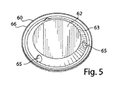
電池ハウジング70内の本発明のエンドキャップ組立体14の好ましい構造が、図1Aに例示されている。本発明のエンドキャップ組立体14は開放端部15と対向する閉鎖端部17とを有する円筒形ハウジング70(図2A)を含む電気化学電池に特に適用性を有し、ここで、エンドキャップ組立体14(図2B)は開放端部15に挿入されて、電池をシールする。エンドキャップ組立体14は標準的な単4(44×10mm)、単3(50×14mm)、単2(49×25.5mm)、及び単1(60×33mm)サイズの円筒形アルカリ電池に特に適用可能である。エンドキャップ組立体14は単4及び単3サイズの電池など、より小さなサイズのアルカリ電池に特に有用であるが、単2及び単1サイズの電池においても同様に、有利に使用されてもよい。電池10(図1A及び1B)のようなこうしたアルカリ電池は望ましくは、亜鉛を含むアノード140と、MnO2を含むカソード120とを有し、それらの間に、電解質透過性のセパレータ130を備えている。カソードはカソード材料120を含む、積み重ねた圧縮ディスク120aの形態であってもよい(図1A)。セパレータ130はハウジングの閉鎖端部17の中央部分に隣接する閉鎖底端部131(図1B)及びエンドキャップ組立体14の底面に隣接する上縁部132(図1A)を有する。アノード140及びカソード120は典型的には、水性水酸化カリウムの電解質を含んでいる。アノード140は亜鉛を含んでいてもよく、カソード120はオキシ水酸化ニッケルを含んでいてもよく、アノード及びカソードは水性水酸化カリウムの電解質を含んでいてもよい。図1Aに示されるように、エンドキャップ60の中央部分62はアノード140と電気接触しており、電池の負極端子を形成する。図1Bに示されるように、ハウジングの閉鎖端部17の中央部分13はカソード120と電気接触しており、及び電池の正極端子を形成する。
A preferred structure of the present
本発明のエンドキャップ組立体14は金属支持ディスク40(図4)、その下にあるシールディスク20(図3)、及び図1Aに最良に示されるように、シールディスク20の中央開口部24を貫通し及びアノード140と接触している集電体(釘)80を含む。図5に最良に示される別個の金属の端子エンドキャップ60が図1A及び2Bに示されるように、金属支持ディスク40の上に積み重ねられる。カソード120、セパレータ130、及びアノード140がハウジング70の内部に挿入された後、エンドキャップ組立体14がハウジングの開放端部15の内部に挿入される。ハウジング70の周囲縁部72がシールシールディスク20の周囲縁部28の上に圧着される。次いで、絶縁シールディスク20の周囲縁部28がエンドキャップ60の周囲縁部66と金属支持ディスク40の縁部49との両方の上に圧着される。圧着プロセスでは、半径方向の力がハウジング70の外面に適用されて、エンドキャップ60の縁部66が絶縁シールディスク20の周囲縁部28に確実に嵌合するようにしてもよい。半径方向圧縮力は金属支持ディスク40を半径方向に圧縮させ、及び金属支持ディスク40の縁部49が絶縁シールディスク20の縁部28に対して確実に押し付けられるか又はしっかりと嵌合するようにし、それによって非常に有効なシールを生成する。
The
金属支持ディスク40(図1A及び4)は好ましくは、中央に位置する開口部41をその中に有する、実質的に平坦な中央部分43を有する。金属支持ディスク40は好ましくは、回旋状の表面を有する一体成形の金属構造のディスクから形成されている。エンドキャップ組立体14を上にした垂直位置で電池を見るとき、金属支持ディスク40の一部分は電池の中心長手方向軸190に近い低点から電池ハウジング側壁74に向かう方向にある高点まで上方に傾斜する径方向に延在する壁46を有する。上方に傾斜する壁46はそれを通る少なくとも1つの破裂開口部48を有する。金属支持ディスク40はニッケルメッキ付きの冷間圧延鋼、ステンレス鋼又は低炭素鋼など、良好な機械的強度及び耐食性を有する導電性金属で構成されている。金属支持ディスク40は好ましくは、単4については約0.50mmの厚さ、単1電池については約0.80mmまでの厚さの回旋状の表面を有する炭素鋼からできている。好ましくは、図4に最良に示されるように、直径方向に対向する同じサイズの一対の開口部48が金属支持ディスク40の上方に延在する壁46の中に位置している。エンドキャップ組立体14を上にした垂直位置で電池を見るとき、金属支持ディスク40の上方に延在する壁46は支持ディスク40の壁46上の低点46aから壁46上の高点46bまで上方に延在する。支持ディスク40の上方に延在する壁46は上方傾斜の方向において直線状であることもできるし、電池の外側から見るとき、僅かに凹形の表面輪郭(内向き又はボウル形の形状の湾曲)を有することもできる。上方に延在する表面46は周囲縁部49の中で終端する。
The metal support disk 40 (FIGS. 1A and 4) preferably has a substantially flat
絶縁シールディスク20(図1A及び3)は上方に延在する壁26を含む回旋状の表面を有し、図1Aに示されるように、その表面の一部分は金属支持ディスク40の開口部48の下にありかつ隣接する。エンドキャップ組立体14を上にした垂直位置で電池を見るとき、絶縁シールディスク20の一部分は電池の中心長手方向軸190に近い低点から電池ハウジング側壁74に向かう方向にある高点まで上方に傾斜する径方向に延在する壁26を有する。エンドキャップ組立体14を上にした垂直位置で電池を見るとき、シールディスク20の壁26はその表面上の低点26aからその表面上の高点26bまで上方に延在する。絶縁ディスク20の上方に延在する壁26は好ましくは僅かに凹形の輪郭を有するが、またハウジングの開放端部15から見るとき、真っ直ぐであっても、実質的に真っ直ぐであってもよい。上方に延在する壁26は絶縁シールディスク20の周囲縁部28aのところ又はその近くの高点26bのところで終端する。
Insulating seal disk 20 (FIGS. 1A and 3) has a convoluted surface including an upwardly extending
金属支持ディスク40は従来の構成からは逆転している径方向に延在する壁46を有することが観察されることになる。図1Aに示される具体的な実施形態では、エンドキャップ組立体14を上にして電池を見るとき、金属支持ディスク40の径方向に延在する壁46は電池の長手方向軸190に近い、ディスク基底部43のところ又はその近くの低点から延在しかつそこからディスクの周囲縁部49に向かって傾斜して上方に延在する。即ち、金属支持ディスク40の径方向に延在する壁46は電池の中心長手方向軸190に最も近い径方向に延在する壁の縁部又は部分がディスクの周囲縁部49に最も近い径方向に延在する壁の縁部又は部分より低くなるように、上方に傾斜している。したがって、エンドキャップ組立体14を上にして電池を見るとき、金属支持ディスク40の径方向に延在する壁46は凹形又はボウル形の形状の壁を形成する。したがって、金属支持ディスク40の径方向に延在する壁は米国特許第6,887,614号に示される構成と比べるとき、逆転した構成を有するように見える。この今挙げた参照文献の金属支持ディスクはまた、傾斜して径方向に延在する壁を有する。しかし、エンドキャップ組立体を上にして電池を見るとき、前記参照の電池の中心長手方向軸に最も近い径方向に延在する壁の部分は支持ディスクの周囲縁部に最も近い径方向に延在する壁の部分より高い。これは、電池の中心長手方向軸190に最も近い壁46の部分がディスクの周囲縁部49に最も近い径方向に延在する壁46の部分より低いように、径方向に延在する壁46が上方に傾斜している、本発明の金属支持ディスク40の上記の構成の反対である。したがって、本発明の金属支持ディスク40の上方に延在する壁46は逆転して見え、即ち、米国特許第6,887,614号に示される金属支持ディスクの凸形の形状と比べるとき、凹形の形状に見える。
It will be observed that the
同様に、金属支持ディスク40の下にある絶縁シールディスク20は上記の金属支持ディスク40の径方向に延在する壁46と同じく上方への傾斜を有する径方向に延在する壁26を有する。具体的には、電池の中心長手方向軸190に最も近い、絶縁シールディスク20の径方向に延在する壁26の部分はシールディスク20の周囲縁部28aに最も近い、径方向に延在する壁26の部分より低い。絶縁シールディスク20の上方に傾斜する径方向に延在する壁26は望ましくは、覆っている金属支持ディスク40の上方に傾斜する径方向に延在する壁46と同じ傾斜度を有する。したがって、絶縁シールディスク20の上方に傾斜する径方向に延在する壁26は覆っている金属支持ディスク40の上方に傾斜する径方向に延在する壁46に隣接する。好ましくは、絶縁シールディスク20の上方に傾斜した径方向に延在する壁26は金属支持ディスク40の上方への径方向に延在する壁46に対して面一であるか又はほぼ面一である。電池が完全に組み立てられた後、金属支持ディスク40の上方に傾斜する径方向に延在する壁46と隣接する絶縁シールディスク20の上方に傾斜する径方向に延在する壁26との間の平均空隙は約0.5mm未満である。好ましくは、2つの上方に延在する壁26と46との間の平均空隙は約0.1〜0.5mmである。
Similarly, the insulating
エンドキャップ組立体を上にして電池を見るとき、金属支持ディスク40の径方向に延在する壁46及びその下にありかつ隣接する絶縁シールディスク20の径方向に延在する壁26は凹形又はボウル形の形状の壁を形成し、カソード材料のためにより多くの高さが利用可能である。即ち、カソード材料120のために利用可能なカソードカラム125の高さは先行技術の米国特許第6,887,614号に示される設計の中のものより大きい。これは、金属支持ディスク40の径方向に延在する壁46及びその下にある絶縁シールディスク20の径方向に延在する壁26が電池の中心長手方向軸190に近い低点から電池ハウジングの側壁74に向かう方向にある高点まで径方向において上方に傾斜しているためである。こうした構成は絶縁シールディスク20の基底部からカソードカラム125の中へと延在する周辺スカートの必要性を排除する。(こうしたスカートは多くの場合、従来の絶縁シールディスクの一体機構でありかつセパレータシートの上縁を収容する目的で用いられる。)これらの要因、即ち上方に傾斜した径方向に延在する壁25、及びシールディスクの基底部から生じるスカートの排除は次には所与の電池サイズについて、より多くの高さまでカソード材料120が電池ハウジング70の中に装填され得るように、カソードカラム125のためにより多くの利用可能な高さを結果として生じる。これはカソード120の幅が低減され得ることを意味し、それはより良好な電池放電性能を結果として生じ得るか、又は別の方法としてはより高い放電能力(mA−hr)を結果として生じ得るカソード材料のより多くの装填を可能にする。
When viewing the battery with the end cap assembly up, the
その上、金属支持ディスク40の径方向に延在する壁46及びその下にある絶縁シールディスク20の径方向に延在する壁26の両方の凹形の(逆転した)形状はアノードカラム140のプラグ21を生成する。プラグ21は図1Aに示されるように、ハブ22の基底部29及び絶縁シールディスク20の上方に延在する壁26の少なくとも一部分から形成される。具体的には、絶縁シールディスクの径方向に延在する壁26の凹形の形状はアノードカラム145の(開放)端部を直接塞ぎ、したがってアノードカラム145のより有効なシールを提供する。また、エンドキャップ組立体を上にして電池を見るとき、絶縁シールディスク20の径方向に延在する壁26の凹形の(逆転した)ボウル形の形状の構成はセパレータ130の上縁部132が絶縁シールディスク20の径方向に延在する壁26の下面に沿って外側及び上方にかつカソードカラム125の上部に向かう方向に傾斜できるようにする。カソードディスク120aはセパレータ130の上縁部132を押し付け、それによって上縁部132を、絶縁シールディスク20の径方向に延在する壁26の下面に押し付けて保持する。これはアノード及びカソードカラムの間により有効な仕切りを提供し、アノード及びカソード材料の高い装填のときでさえ、アノード材料140がカソードカラム125の中にこぼれるのを防ぐ。
In addition, the concave (reversed) shape of both the
金属支持ディスク40の開口部48の下にある上方に延在する表面26の部分は(図1A)、ハウジングの開放端部15に面するその上側表面の上にオーバーカット溝210を有する。溝210は開放縁部及び対向する閉鎖基底部を有する。溝の基底部は薄くされた破裂可能な薄膜23を形成する。破裂可能な薄膜23は金属支持ディスク40の開口部48に隣接する。電池内のガス圧力が上昇するとき、破裂可能な薄膜23は開口部48を貫通し破裂して、それによって薄膜23の上のヘッドスペース18、即ち薄膜23と覆っているエンドキャップ60との間の空隙にガスが放出される。エンドキャップ60は壁63を通るガス抜き開口部65を有し、壁63は中央端子部分62から下向きに延在する(図5)。ガスは次いで、エンドキャップ60中のガス抜き開口部65を通って外部環境に通過する(図1A及び5)。好ましくは、絶縁ディスク20の上方に延在する壁26は組立の間、金属支持ディスク40の上方に延在する壁46の内面に対して面一である。絶縁シールディスク20の周囲縁部28が金属支持ディスクの縁部49とエンドキャップの縁部66の両方の上に緊密に圧着されることを確実にするために、十分な力が圧着の間に適用されなければならないのにもかかわらず、驚くべきことに、絶縁ディスク20の上方に延在する壁26は金属支持ディスク40の上方に延在する壁46に対して面一であるか又はほぼ面一であるように維持される。即ち、開放端部15においてハウジング70に対して適用される半径方向圧縮力を含む圧着力は絶縁ディスク20の上方に延在する壁26が金属支持ディスク40の上方に延在する壁46に対して実質的に面一であることを排除しない。圧着力は上方に延在する壁26と46との間に平均して約0.50mmを超える空隙を作り出さず、典型的には、圧着力は上方に延在する壁26と46との間に平均して約0.35mmを超える空隙を作り出さない。圧着力は典型的には、上方に延在する壁26と46との間に平均して約0.1mm〜0.50mmの空隙を作り出すことができる。
The portion of the upwardly extending
溝210は好ましくは、図1A及び3に最良に示されるように、上方に延在する壁26の上側部に沿って円周方向に広がっている。溝210は好ましくは、絶縁シールディスク20の上方に延在する壁26の上側部に沿って円周方向に広がる薄くされた部分23を形成している(図1A)。包囲する溝210(図1A)は薄くされた部分、即ち包囲する薄膜23を溝210の基底部に形成している。薄くされた部分23は図1に示されるように、金属支持ディスク40の上方に延在する壁46に面しかつ好ましくは隣接する破裂可能な薄膜を形成している。1つ以上の開口部48が金属支持ディスク40の上方に延在する壁46内に存在し得る(図1A及び4)。好ましくは、図4に示されるように、2つの開口部が上方に延在する壁46の表面内に存在する。2つの開口部48が用いられる場合、それらは望ましくは、およそ同じサイズでありかつ上方に延在する壁46上にそれぞれが直径方向に対向して位置する(図4)。開口部48のすぐ下で広がる、包囲する薄くされた薄膜23の部分は破裂可能な部分を形成する。電池内のガスが所定レベルに増加するとき、開口部48のすぐ下の薄膜23の部分は張力下で破裂するまで開口部の中へと伸張し、それによって、電池内からガスを放出する。電池の内部圧力は上にあるエンドキャップのガス抜き開口部65を通じて環境までガスが流出すると、直ちに低減される。
The
溝210の深さを規定する対向する溝の壁212a及び212bはいずれかの特定の形状の湾曲をなす必要はない。しかしながら、製造を容易にする観点から、溝の壁212a及び212bは垂直に向けられることが可能であり、又は溝210の口部が溝の基底部(破裂可能な薄膜部分23)よりも幅広となるように傾斜していてもよい。薄膜は好ましくは、剪断ではなく引張で破裂するように意図されているので、212aの角度は薄膜23の破裂性の要因とはならない。壁212a及び212bは好都合にも、溝210の基底部において破裂可能な薄膜23に対して直角をなすこともできるし、図1Aに示されるように破裂可能な薄膜23と鈍角を形成することもできる。あるいは、溝の壁212a及び212bは平坦な又は湾曲した表面で形成されることもできる。望ましくは、壁212a及び212bはそれぞれが破裂可能な薄膜23との、望ましくは約120〜135°の鈍角を形成する平坦な表面を形成し、したがって、溝210の開放端部は薄膜23を形成する溝の基底部よりも僅かに幅広となる。こうした好ましい実施形態により、包囲する溝210は図1Aに示されるような台形の形状が与えられる。こうした構成は射出成形による製造を容易にする観点から望ましく、薄膜23の破裂性に影響を及ぼすことはない。
The opposing groove walls 212a and 212b that define the depth of the
上方に延在する壁26及びその中の破裂可能な薄膜部分23は望ましくは、図1に例示されるように、電池の中心長手方向軸190から鋭角(90°未満の角度)で傾斜している。こうした構成において、上方に延在する壁26及びその中の薄膜部分23は電池の中心長手方向軸に平行でない。好ましくは、上方に延在する壁26は長手方向軸190から約15〜80°の鋭角で傾斜している(図1A)。同様に、支持ディスク40の上方に延在する壁46は好ましくは、シールディスク20の上方に延在する壁26と同じ鋭角で、即ち中心軸190から約15〜80°で傾斜している。したがって、支持ディスク40がシールディスク20の上に置かれるとき、支持ディスク40の上方に延在する壁46はシールディスク20の上方に延在する壁26と隣接しかつ面一になり、破裂可能な薄膜23は開口部48と隣接する。上述したように、エンドキャップ縁部66及び金属支持縁部49の両方の上に同時にシール縁部28を圧着させるために、より大きな圧着力が必要となるにもかかわらず、金属支持ディスクの上方に延在する壁46とシールディスクの上方に延在する壁26が面一で(又はほぼ面一で)維持され得ると判断された。金属支持ディスク40の上方に延在する壁46が傾斜した向きをなすことで、支持ディスク40の所与の全高に対して、より大きな直径の開口部48を上方に延在する壁46内に作製することが可能となる。これにより、次には、所与の薄い厚さの薄膜23がより低い閾値圧力で破裂できるようになり、それによって電池ハウジング70の壁厚を低減できる。ハウジング70の壁厚が減じられると、アノード及びカソード活性材料に利用可能な電池の内容積が増加し、それによって電池の容量が増加する。
The upwardly extending
絶縁シールディスク20はプラスチック絶縁材料の一体成形構造から形成されてもよく、好ましくは、耐久性及び耐食性の射出成形ナイロンにより成形される。図1A及び図3に最良に例示されるように、絶縁ディスク20はその中心を通る開口部24を有する中央ボス又はハブ22を有する。ボス(ハブ)22はディスク20のうちの最も厚く及び最も重量のある部分を形成している。エンドキャップ組立体を上にした垂直位置で電池を見るとき、ボス22の周囲縁部は上方に延在する壁26において終端しており、この上方に延在する壁26は壁26上の低点26aから壁26上の高点26bまで上方に延在する(図1A及び3)。同様に、支持ディスク40の中央部分43の周囲縁部は壁46上の低点46aから壁46上の高点46bまで上方に延在する壁46において終端している(図1A及び4)。
The insulating
また、上記の絶縁シールディスク20の構成により、破裂可能な薄膜23がエンドキャップ60に、より近接して配置される。これは活性材料用に利用可能な電池内のより多くの内部空隙があることを意味する。特に、破裂可能な薄膜23をその中に有する絶縁シールディスク壁26の上方傾斜は所与のサイズの電池について、より大きい高さのカソードカラム125を提供する。絶縁ディスク20の上方に延在する壁26上の破裂可能な薄膜23の位置により、ガス及び他の内部成分は薄膜23が破裂した後、電池内部から金属支持ディスク中の開口部48を通り、次いでエンドキャップ60の中の開口部65を通って直接環境まで、妨げられることなく通過することができる。電池内部から環境へのガスのこうした通過は電池が他の電池又は給電されている装置に接続されているときにも妨げられることがない。
In addition, the rupturable
破裂可能な薄膜をシール内に形成する溝がない場合、即ち、開口部48に隣接する上方に傾斜する壁26の部分全体が均一な一定の厚さでありかつ破裂可能な薄膜を形成している場合、近似を適用するために、所望の破裂圧力PRと、破裂開口部48の半径「R」と、結果として得られる一定の厚さの薄膜の厚さ「t」との間に以下の関係が決定されており、ここで「S」は破裂可能な材料の極限引張強さである。
Pr=t/R×S (I)
In the absence of a groove forming a rupturable film in the seal, i.e., the entire portion of the upwardly sloping
P r = t / R × S (I)
複数のガス発生抑制剤の使用により、電池のガス発生を低減することは可能になっている。開口部48の半径を大きくし、一定の厚さの薄膜の厚さを可能な限り薄くすることが望ましい。これによって、所望であれば、電池内で増加したガスのより低い閾値圧力Pでの薄膜の破裂が可能となる。したがって、所与の電池のサイズに対し、実現可能な最大の開口部半径及び最小の膜厚によって決まる爆発圧力に、実際的な下限が存在する。破裂可能な薄膜を形成するオーバーカット溝210を加えることは溝の深さ及び幅など、爆発圧力をより低いレベルへと操作する更なる変数を提供する。
By using a plurality of gas generation inhibitors, it is possible to reduce the gas generation of the battery. It is desirable to increase the radius of the
エンドキャップ組立体14において、破裂可能な薄膜の幅(即ち、溝210の基底部の幅)と破裂可能な薄膜23の厚さとの比は典型的には、約1:1〜12.5:1である。エンドキャップ組立体14のこの設計では、単4サイズの電池と単1サイズの電池との間の電池の一般的な電池サイズに対し、典型的には約1.8〜10mm(円の直径)の大きさの開口部48を金属支持ディスク40の上方傾斜壁46に備えることができる。
In the
以下の薄膜23のより低レベルの破裂圧力が本発明のエンドキャップ組立体14に関して望ましい。単4のアルカリ電池に対し、薄膜23の目標破裂圧力は望ましくは約6.21MPa〜12.41MPaG(900〜1800psig)である。単3のアルカリ電池に対し、薄膜23の目標破裂圧力は望ましくは約3.45MPa〜10.34MPaG(500〜1500psig)である。単2サイズのアルカリ電池に対し、薄膜23の目標破裂圧力は望ましくは約2.07MPa〜3.79MPaG(300〜550psig)である。単1サイズのアルカリ電池に対し、薄膜23の目標破裂圧力は望ましくは約1.38MPa〜2.76MPaG(200〜400psig)である。こうした破裂圧力の範囲は非限定的な例として意図されたものである。本発明のエンドキャップ組立体14はより高くかつより低い破裂圧力でも同様に用いられ得るため、エンドキャップ組立体14がこれらの破裂圧力の範囲に限定されるようには意図されていないことが理解されよう。
The following lower level burst pressure of the
所与の電池サイズについて上述の破裂圧力の範囲では、ニッケルメッキ鋼のハウジング70は典型的には単3及び単4に対しては望ましくは約0.15〜0.30mm(0.006〜0.012インチ)、好ましくは約0.15〜0.20mm(0.006〜0.008インチ)の、また、単2及び単1に対しては約0.25〜0.30mm(0.010〜0.012インチ)の薄い壁厚を有してもよい。ハウジング70の壁厚はより薄いことが望ましいが、これはその結果として、電池の内容積が増加し、より多くのアノード及びカソード材料を使用することができ、それによって電池の容量が増加するからである。エンドキャップ組立体14は所与の電池のサイズに対して上述の破裂圧力を実現することができ、また、エンドキャップ60が「不正開封防止」をなすという更なる機能を有する。即ち、エンドキャップ60の縁部66は絶縁シールディスク20の周囲縁部28の下に圧着されるので、エンドキャップ組立体から容易には取り出され得ない。したがって、本発明のエンドキャップ組立体14の設計においては、電池の内容物も同様に、非常に安全であり、悪意による不正開封に対して十分に保護される。加えて、本発明のエンドキャップ組立体14において、アノード集電体用の釘80の頭部85はエンドキャップ60の下面に直接溶接される。これは、単純な電気抵抗溶接によって実現され得る。本発明のエンドキャップ組立体14においては、他のいずれの電池構成要素の溶接も必要なく、またレーザー溶接も必要なく、したがって電池の構築が単純化される。
For the range of burst pressures described above for a given battery size, nickel plated
本明細書で記載されるエンドキャップ組立体に関連して、より大きいサイズの開口部48を用いるという要望に沿うと、これは破裂可能な薄膜23を含有する絶縁シール壁26を傾斜させる、即ち長手方向軸190に非平行に配向することにより、最良に実現できると判断された。好ましくは、シール壁26及びそれに隣接する金属支持表面46は中心長手方向軸190から好ましくは約15〜80°の角度で上方に傾斜している。これは、上記のように、開口部48を形成するために、より多くの利用可能な表面積を提供し、カソードカラム125の高さを増加する。
In line with the desire to use a larger size opening 48 in connection with the end cap assembly described herein, this causes the insulating
電池の爆発圧力を低減するという要望に沿うと、これはオーバーカット溝210をシールディスク20の上方傾斜壁26の上面の上に形成することにより実現され得ると判断された。こうした構成では、図1Aに示されるように、溝210の基底部における破裂可能な薄膜23はハウジングの開放端部15に面する。こうしたオーバーカット溝210は例えば、シールディスク20を形成するときの射出成形の間に、シールディスク20の中心を包囲して形成され得る。あるいは、溝の基底部における破裂可能な薄膜23がその結果電池内部に面するように、溝210はアンダーカット溝(示されず)であってもよい。
In line with the desire to reduce the explosion pressure of the battery, it has been determined that this can be achieved by forming an
非限定的な例として、単3サイズのアルカリ電池を用いる好ましい実施形態では、破裂可能な薄膜23は電池内のガスが約3.45MPa〜10.34MPaG(500〜1500psig)のレベルまで増加したときに破裂するように設計され得る。金属支持ディスク40の中の開口部48の下にある破裂可能な薄膜の部分23は望ましくはナイロン、好ましくはナイロン66又はナイロン612から形成されるが、またポリプロピレン及びポリエチレンのような他の材料から形成されることもできる。溝210は約0.08〜1mm、望ましくは約0.08〜0.8mmの幅を有することができる。図1Aに示されるように、溝210は好ましくは、絶縁ディスク20の上方に延在する壁26の上面の周りで円周方向に広がっている。円周方向の溝210のある区分は金属支持ディスク40の中の開口部48のすぐ下に広がっている。あるいは、溝210は個々の溝が開口部48のすぐ下にカットされ、それらの間の壁26の内面の部分は平坦及びカットされず残るように、包囲される必要なく区分で形成されることもできる。単4サイズの電池と単1サイズの電池との間の電池の一般的な電池サイズに対し、開口部48は約2.5〜78.5mm2の面積に対応する直径約1.8〜10mm、典型的には、約3.1〜63.6mm2の面積に対応する2〜9mm(円の直径)を有する円形形状のものであり得る。開口部48が長方形又は楕円形などの他の形状であり得ることは理解されるべきである。また、開口部48は矩形若しくは多角形形状又は真っ直ぐな表面と湾曲した表面との組み合わせを含む不規則な形状でもあり得る。また、こうした長方形若しくは多角形形状又は他の不規則な形状の有効径は望ましくは約2〜9mmである。こうした形状の有効径はいずれかのこうした開口部を横切る最小距離として定義され得る。
As a non-limiting example, in a preferred embodiment using AA alkaline batteries, the rupturable
目標破裂圧力が単3電池に対して約3.45〜10.34MPaG(500〜1500psig)、又は、単4サイズの電池に対して約6.21〜12.41MPaG(900〜1800psig)であるとき、溝の幅(溝の基底部における薄膜23の幅)と破裂可能な薄膜23の厚さとの比は望ましくは約1:1〜12.5:1である。この範囲の比に従って、溝の基底部における溝の幅は望ましくは約0.1〜1mm、好ましくは約0.4〜0.7mmであり、破裂可能な薄膜23の厚さは約0.08〜0.25mm、望ましくは約0.10〜0.20mmである。開口部48は約2.5〜16mm2の面積に対応する、典型的には約1.8〜4.5mmの直径を有することができる。
When the target burst pressure is about 3.45-10.34 MPaG (500-1500 psig) for AA batteries, or about 6.21-12.41 MPaG (900-1800 psig) for AAA size batteries The ratio of the width of the groove (the width of the
単2及び単1のアルカリ電池が用いられるとき、破裂可能な薄膜23は望ましくは、より低い圧力で破裂するように設計される。例えば、単2サイズの電池に対し、目標破裂圧力は約2.07〜3.79MPaG(300〜550psig)であってもよい。単1サイズの電池に対しては目標破裂圧力は約1.38〜2.76MPaG(200〜400psig)であってもよい。望ましくは約1:1〜12.5:1である溝の幅(溝の基底部における薄膜23の幅)と破裂可能な薄膜23の厚さとの同じ比も適用可能である。
When single 2 and single 1 alkaline cells are used, the
一般に、電池のサイズに関わりなく、破裂可能な薄膜23の厚さと薄膜23に近接する上方に延在するシール壁26の厚さとの比が1:2以下、望ましくは約1:2〜1:10、より典型的には約1:2〜1:5であるように維持されることは望ましい。こうした実施形態において、破裂可能な薄膜23の厚さは望ましくは、約0.08〜0.25mm、好ましくは約0.1〜0.2mmである。薄膜23がそれを通って破裂する開口部48は望ましくは約1.8〜10mmの直径を有する。
In general, regardless of the size of the battery, the ratio of the thickness of the rupturable
組み立てにおいて、アノード140、カソード120、及びセパレータ130が電池のハウジング70の内部に挿入された後、エンドキャップ組立体14がハウジングの開放端部14に挿入される。金属支持ディスク40は最初に、ボス22の上面25が金属支持ディスク40の中央開口部41へ貫通するように、絶縁シールディスク20に押し付けられてもよい。図1Aに示される実施形態では、絶縁シールディスク20の上方に延在する壁26が金属支持ディスク40の上方に延在する壁46に隣接するように、ボス22の本質的にすべてが金属支持ディスク40中の開口部41に押し通される。絶縁ディスク20の上方に延在する壁26は上にある金属支持ディスク40の上方に延在する壁46の内面に対して面一である。金属支持ディスク40をその中に収容した絶縁シールディスク20は次いで、ハウジング70の開放端部15に挿入されてもよい。絶縁シールの周囲縁部28の下部分28aは電池ハウジングの側壁74内の円周方向のビード73上に載置されている。集電体用の釘80の頭部85は好ましくは、電気抵抗溶接によってエンドキャップ60の下面に溶接される。
In assembly, after the
集電体用の釘80がエンドキャップ60に溶接されたあと、それは次に金属支持ディスク40の開口部41を通り、次いでその下にある絶縁シールディスク20内のその下にある中央開口部24を通って、集電体の先端84がアノード140材料の中に貫通するまで挿入される。エンドキャップ60の縁部66は金属支持ディスク40の縁部49の上で止まる。金属支持ディスク40の縁部49と、覆っているエンドキャップ60の縁部66の両方は図1Aに示されるように、絶縁シールディスク20の周囲縁部28の内側にある。次いで、ハウジング70の縁部72は絶縁シールディスク20の周囲縁部28の上に圧着される。次に、絶縁シールディスクの縁部28は金属支持ディスク40の縁部49とエンドキャップ60の縁部66の両方の上に圧着され、エンドキャップ60とその下にある金属支持ディスク40を、絶縁シールディスク20の上の所定位置に安定して固定する。したがって、絶縁シールディスク20、金属支持ディスク40、及び覆っているエンドキャップ60はハウジングの開放端部15内で固定され、それによって電池のハウジングが閉鎖される。エンドキャップ60の周囲縁部66が絶縁シールディスク20の周囲縁部28に嵌合することを確実にするため、及び金属支持ディスクの縁部49が半径方向に圧縮され、それによってしっかりとしたシールの実現を助けることを確実にするため、半径方向の圧縮力が圧着の間にハウジング70に加えられてもよい。エンドキャップ60の縁部66は手で触れることができず、したがって、エンドキャップ60は不正開封防止をなすと見なされ、即ち、電池組立体から容易に取り出されない。
After the
絶縁シールディスク20の別の実施形態では、ディスクが形成された後に、加熱された道具の助けにより又はその助けなしに、ダイ又はナイフの刃でシールディスク20の上方に延在する壁26の下面220に打抜き又は型押し加工により溝210が形成され得ることを除き、ディスクの構成は図1A及び図3に示されるものと同じであり得る。こうした実施形態では、シールディスク20は最初に、均一な厚さの、即ち溝210のない上方に延在する壁26を得るように成形することによって形成され得る。次いで、環状の刃先を有するダイがシールディスクの上方に延在する壁26の下面220に適用され得る。幅1mm未満、望ましくは約0.08〜1mm、好ましくは0.08〜0.8mmの溝210を形成する環状又は円弧状の切り込みがこのようにして、シールディスク20の上方に延在する壁26の上面に作製され得る。溝210は破裂可能な薄膜23を溝の基底部に形成する。溝210によって形成された破裂可能な薄膜23はシールディスクの上方に延在する壁の表面220に、弱い区域を形成する。溝210は打抜きダイ、例えば隆起したナイフの刃を有するダイの使用により作製されることができ、これはまた加熱されることもでき、上方に延在する壁26の下面の上に押し付けられる。このようにして作製された溝210により、溝210の基底部の薄膜23は溝210が上方に延在する壁26内に成形される場合よりも薄く形成され得る。打抜きダイによって形成された溝210はしたがって、幅が非常に狭く及び厚さが非常に薄い破裂可能な薄膜23を結果として生じ得る。溝の切り込み210によって形成された薄膜23(図1A)は切り込みの深さを調整し、次にはこれによって所望の厚さの破裂可能な薄膜23を切り込みの基底部に形成することによって、所望の目標圧力で破裂するように設計され得る。
In another embodiment of the insulating
溝の切り込み210によって形成された薄膜23は金属支持ディスク40の上方に延在する壁46の下面に隣接する。薄膜23の一部分は図1Aに示される実施形態に関連して記載したのと同じ方式で、金属支持ディスク40の上方に延在する壁46内の1つ以上の開口部48の下であり得る。溝の切り込み210(図1A及び3)は連続的な閉じた円の形状でなくてもよいが、好ましくは、開口部48の下にある溝210の部分が開口部48の全幅にわたって連続的となるように十分に長い円弧状の区分であり得ることが理解されよう。即ち、溝210は開口部48の上にない上方に延在する壁46の部分まで延びていなくてもよい。
The
具体的な実施形態では、非限定的な例として、電池のサイズに関わりなく、シールディスク20はナイロン製であることができ、溝の切り込み210は典型的には約0.08〜1.0mm、好ましくは約0.08〜0.8mmの幅を有することができる。溝の切り込みの基底部に形成された薄膜23は薄膜23の厚さと溝210に近接する上方に延在する壁26の厚さとの比が約1:10〜1:2、好ましくは約1:5〜1:2となるような厚さを有することができる。こうした実施形態では、破裂可能な薄膜23の厚さは典型的には約0.08〜0.25mm、望ましくは約0.1〜0.2mmであってもよい。
In a specific embodiment, as a non-limiting example, regardless of the size of the battery, the
ナイロンは絶縁ディスク20及びそれと一体の破裂可能な薄膜の部分23に好ましい材料であるが、他の材料、好ましくは水素透過性で耐食性であり耐久性のあるプラスチック材料、例えばポリスルホン、ポリエチレン、ポリプロピレン、又はタルク充填ポリプロピレンもまた好適であることはまた理解されるべきである。薄膜23の厚さと開口部48のサイズの組み合わせは用いられる材料の極限引張強さ及び破裂が意図されるガス圧力のレベルに応じて調整されてもよい。開口部48を1つのみ、そしてそれに対応する1つの破裂可能な薄膜23を用いることが適切であると判断された。しかしながら、金属支持ディスク40内の上方に延在する壁46はその下にある1つ以上の破裂可能な薄膜の部分23と隣接する、同等のサイズの複数の開口部を設けてもよい。好ましくは、図4に示されるように、金属表面46中の直径方向に対向する2つの開口部48を用いることができる。これによって、薄膜が破裂し、ガス抜きが所望のガス圧力で生じることが更に確実となる。
Nylon is the preferred material for the insulating
電池のサイズに関わりなく用いられてもよい、アルカリ電池10用のアノード140、カソード120、及びセパレータ130の代表的な化学組成物を以下に説明する。次の化学組成物は本発明のエンドキャップ組立体14を有する電池中に使用するための代表的な基礎的組成物であり、そのようなものとして、限定することを意図していない。
Exemplary chemical compositions of
上述の実施形態において、代表的なカソード120は二酸化マンガン、グラファイト、及び水性アルカリ電解質を含むことができ、アノード140は亜鉛及び水性アルカリ電解質を含むことができる。水性の電解質は従来のKOH、酸化亜鉛、及びゲル化剤の混合物から構成されている。アノード材料140は水銀を含有しない(水銀無添加の)亜鉛合金粉末を含有するゲル状混合物の形態であることができる。即ち、電池は電池総重量の約50ppm部未満、好ましくは電池総重量の20ppm部未満の総水銀含有量を有し得る。電池はまた、好ましくは、いずれの鉛添加量も含有せず、したがって本質的に無鉛であり、即ち、総鉛含有量はアノードの総金属含有量の30ppm未満、望ましくは15ppm未満である。このような混合物は典型的には、KOH電解質水溶液、ゲル化剤(例えば、B.F.グッドリッチ(B.F.Goodrich)から商標名カーボポール(CARBOPOL)C940として入手可能なアクリル酸コポリマー)、及び界面活性剤(例えば、ローヌ・プーラン(Rhone Poulenc)から商標名GAFAC RA600として入手可能な有機リン酸エステル系界面活性剤)を含有することができる。こうした混合物は単に実例として与えるにすぎず、本発明を制限しようとするものではない。亜鉛アノード用の他の代表的なゲル化剤は米国特許第4,563,404号に開示されている。
In the embodiments described above, the
カソード120は望ましくは次の組成物を有することができる。
87〜93重量%の電解二酸化マンガン(例えば、カーマギー社(Kerr-McGee)によるTrona D)、2〜6重量%(合計)のグラファイト、約30〜40重量%の濃度のKOHを有する5〜7重量%の7〜10NのKOH水溶液、及び、0.1〜0.5重量%の光学用ポリエチレン結合剤という組成を有することができる。電解二酸化マンガンは典型的には約1〜100マイクロメートル、望ましくは約20〜60マイクロメートルの平均粒径を有する。グラファイトは典型的には、天然、若しくは膨張グラファイト又はこれらの混合物の形態である。また、グラファイトはグラファイト状炭素ナノ繊維を単独で又は天然若しくは膨張グラファイトとの混合により含むことができる。こうしたカソード混合物は例示を目的としたものであって、本発明を制限しようとするものではない。 5-7 with 87-93 wt% electrolytic manganese dioxide (e.g. Trona D by Kerr-McGee), 2-6 wt% (total) graphite, about 30-40 wt% KOH concentration It can have a composition of 7% by weight 7-10 N aqueous KOH and 0.1-0.5% by weight optical polyethylene binder. Electrolytic manganese dioxide typically has an average particle size of about 1 to 100 micrometers, desirably about 20 to 60 micrometers. The graphite is typically in the form of natural or expanded graphite or mixtures thereof. Graphite can also contain graphitic carbon nanofibers alone or mixed with natural or expanded graphite. Such cathode mixtures are for illustrative purposes and are not intended to limit the invention.
アノード材料140は亜鉛合金粉末62〜69重量%(合金及びメッキ材料として200〜500ppmのインジウムを含有する99.9重量%亜鉛)、38重量%のKOHと約2重量%のZnOとを含むKOH水溶液;B.F.グッドリッチ(B.F. Goodrich)から商標名「カーボポール(CARBOPOL)C940」として市販される架橋アクリル酸ポリマーゲル化剤(例えば0.5〜2重量%)、及びグレイン・プロセシング社(Grain Processing Co.)から商標名「ウォーターロック(Waterlock)A−221」として市販される、デンプン主鎖上にグラフトされた加水分解ポリアクリロニトリル(0.01〜0.5重量%);ローヌ・プーラン(Rhone-Poulenc)から商標名「RM−510」として市販されるジオニル(dionyl)フェノールリン酸エステル界面活性剤(50ppm)を含む。亜鉛合金の平均粒度は望ましくは約30〜350マイクロメートルである。アノードにおける亜鉛の嵩密度(アノード空隙率)はアノード1立方センチメートル当たり約1.75〜2.2gの亜鉛である。アノード中の電解質水溶液の体積%は好ましくはアノードの約69.2〜75.5体積%である。電池は従来の方式で、MnO2のmA‐hrの容量(MnO21グラム当たり308mA‐hrに基づく)を亜鉛合金のmA‐hrの容量(亜鉛合金1グラム当たり820mA‐hrに基づく)で除した値が約1になるように平衡化され得る。
The
セパレータ130はセルロース系材料からなる従来のイオン多孔質セパレータであり得る。セパレータはセルロース系繊維又はポリビニルアルコール系繊維の不織布材料の内層と、セロハンの外層とを有していてもよい。こうした材料は実例を示すためのものであり、本発明を制限しようとするものではない。ガス発生の抑制を助けるために、集電体80は黄銅、好ましくはスズメッキ付き又はインジウムメッキ付きの黄銅である。
本発明は具体的な実施形態に関して記載されてきたが、本発明の概念の範囲内で変更が可能であることは理解されるべきである。したがって、本発明は本明細書に記載される具体的な実施形態に限定されることを意図せず、請求項及びその等価物の範囲内にある。 Although the invention has been described with reference to specific embodiments, it should be understood that modifications can be made within the scope of the inventive concept. Accordingly, the invention is not intended to be limited to the specific embodiments described herein, but is within the scope of the claims and their equivalents.
Claims (10)
前記エンドキャップ組立体を上にした垂直位置で前記電池を見るとき、前記エンドキャップ組立体が絶縁シールディスク、前記絶縁シールディスクを覆っている金属を含む支持ディスク、前記金属支持ディスクを覆っている金属を含むエンドキャップ、及び前記エンドキャップと電気的に接触している細長い集電体を含み、前記絶縁シールディスクが前記支持ディスク及びエンドキャップを前記電池ハウジングから電気的に絶縁しており、前記絶縁シールディスクが前記電池の中心長手方向軸から90°未満の角度で傾斜して上方に延在しかつ前記長手方向軸に平行でない表面を有するプラスチック材料を含み、前記絶縁ディスクの前記の上方に延在する表面がその上の低点からその上の高点まで上方に延在し、前記エンドキャップ組立体を上にした垂直位置で前記電池を見るとき、前記低点が前記高点よりも前記電池の中心長手方向軸に近く、前記支持ディスクがそれを通る少なくとも1つの開口を有する一体成形の金属構造からなり、前記エンドキャップ組立体を上にした垂直位置で前記電池を見るとき、前記絶縁シールディスクがその中に前記支持ディスク内の前記開口の下にある薄くされた破裂可能な薄膜部分を有する、電気化学電池。 A housing having an open end, an opposed closed end, and a cylindrical sidewall therebetween, and an end cap assembly inserted into the open end of the housing to close the housing. An electrochemical battery, wherein the battery has a positive terminal and a negative terminal,
When viewing the battery in a vertical position with the end cap assembly up, the end cap assembly covers an insulating seal disk, a support disk including a metal covering the insulating seal disk, and the metal support disk. An end cap comprising a metal and an elongated current collector in electrical contact with the end cap, wherein the insulating seal disk electrically insulates the support disk and end cap from the battery housing; An insulating sealing disk comprising a plastic material having a surface extending at an angle of less than 90 ° from the central longitudinal axis of the cell and extending upward and not parallel to the longitudinal axis, above the insulating disk; An extending surface extends upward from a low point above it to a high point above it, and the end cap assembly is When viewing the battery in a vertical position, the low point is closer to the central longitudinal axis of the battery than the high point, and the support disk comprises a one-piece metal structure having at least one opening therethrough. When viewing the battery in a vertical position with the end cap assembly up, the insulating seal disk has a thinned rupturable thin film portion within it under the opening in the support disk. Chemical battery.
前記エンドキャップ組立体を上にした垂直位置で前記電池を見るとき、前記エンドキャップ組立体が絶縁シールディスク、前記絶縁シールディスクを覆っている金属を含む支持ディスク、前記金属支持ディスクを覆っている金属を含むエンドキャップ、及び前記エンドキャップと電気的に接触している細長い集電体を含み、前記絶縁シールディスクが前記支持ディスク及びエンドキャップを前記電池ハウジングから電気的に絶縁し、前記絶縁シールディスクが前記電池の中心長手方向軸から90°未満の角度で傾斜して上方に延在し、前記長手方向軸に平行でない表面を有するプラスチック材料を含み、前記絶縁ディスクの前記の上方に延在する表面がその上の低点からその上の高点まで上方に延在し、前記エンドキャップ組立体を上にした垂直位置で前記電池を見るとき、前記低点が前記高点よりも前記電池の中心長手方向軸に近く、前記ハウジングがその前記開放端部での縁部を有し、並びに前記絶縁シールディスク、金属支持ディスク、及びエンドキャップのそれぞれが周囲縁部を有し、前記支持ディスクが一体成形の金属構造からなり、それを通る少なくとも1つの開口部を有し、その前記開放端部での前記ハウジングの前記縁部が前記絶縁シールディスクの前記周囲縁部の上に圧着されて、前記絶縁シールディスクを前記ハウジング内の所定位置に固定されており、前記絶縁シールディスクの前記周囲縁部が前記エンドキャップ及び前記金属支持ディスクの前記周囲縁部の両方の前記周辺縁部の上に圧着され、それによって前記金属支持ディスク及び前記エンドキャップを前記絶縁シールディスク内の所定位置に固定し、前記エンドキャップ組立体を上にした垂直位置で前記電池を見るとき、前記絶縁シールディスクが前記支持ディスク内の前記開口部の下にあるその表面の一部分を有する、電気化学電池。 A housing having an open end, an opposed closed end, and a cylindrical sidewall therebetween, and an end cap assembly inserted into the open end of the housing to close the housing. An electrochemical battery, wherein the battery has a positive terminal and a negative terminal,
When viewing the battery in a vertical position with the end cap assembly up, the end cap assembly covers an insulating seal disk, a support disk including a metal covering the insulating seal disk, and the metal support disk. An end cap comprising a metal and an elongated current collector in electrical contact with the end cap, wherein the insulating seal disk electrically insulates the support disk and end cap from the battery housing, the insulating seal The disk extends upwardly at an angle of less than 90 ° from the central longitudinal axis of the battery and includes a plastic material having a surface that is not parallel to the longitudinal axis and extends above the insulating disk Surface to extend upward from a low point above it to a high point above it, with the end cap assembly on top When viewing the battery in a straight position, the low point is closer to the central longitudinal axis of the battery than the high point, the housing has an edge at the open end thereof, and the insulating sealing disk; Each of the metal support disk and the end cap has a peripheral edge, and the support disk comprises a one-piece metal structure and has at least one opening therethrough, the housing at the open end thereof The edge of the insulating seal disk is crimped onto the peripheral edge of the insulating seal disk, and the insulating seal disk is fixed at a predetermined position in the housing, and the peripheral edge of the insulating seal disk is fixed to the end. Crimped onto the peripheral edge of both the cap and the peripheral edge of the metal support disk, thereby attaching the metal support disk and the end cap. When the battery is viewed in a vertical position with the end cap assembly up and fixed in place in the insulating seal disk, the surface of the surface of the insulating seal disk below the opening in the support disk is An electrochemical cell having a portion.
Applications Claiming Priority (2)
| Application Number | Priority Date | Filing Date | Title |
|---|---|---|---|
| US11/650,405 US20080166626A1 (en) | 2007-01-05 | 2007-01-05 | End cap seal assembly for an electrochemical cell |
| PCT/IB2008/050020 WO2008084421A1 (en) | 2007-01-05 | 2008-01-04 | End cap seal assembly for an electrochemical cell |
Publications (1)
| Publication Number | Publication Date |
|---|---|
| JP2010515216A true JP2010515216A (en) | 2010-05-06 |
Family
ID=39304598
Family Applications (1)
| Application Number | Title | Priority Date | Filing Date |
|---|---|---|---|
| JP2009543570A Withdrawn JP2010515216A (en) | 2007-01-05 | 2008-01-04 | End cap seal assembly for electrochemical cells |
Country Status (6)
| Country | Link |
|---|---|
| US (1) | US20080166626A1 (en) |
| EP (1) | EP2100340A1 (en) |
| JP (1) | JP2010515216A (en) |
| CN (1) | CN101578720A (en) |
| BR (1) | BRPI0806276A2 (en) |
| WO (1) | WO2008084421A1 (en) |
Cited By (1)
| Publication number | Priority date | Publication date | Assignee | Title |
|---|---|---|---|---|
| JP2016009607A (en) * | 2014-06-25 | 2016-01-18 | 新神戸電機株式会社 | Lithium ion secondary battery and nonaqueous electrolyte secondary battery |
Families Citing this family (7)
| Publication number | Priority date | Publication date | Assignee | Title |
|---|---|---|---|---|
| US8973481B2 (en) | 2003-11-06 | 2015-03-10 | Surefire, Llc | Firearm sound suppressor |
| US8567556B2 (en) | 2012-01-12 | 2013-10-29 | Surefire, Llc | Firearm sound suppressor with inner sleeve |
| US8584794B2 (en) | 2012-01-12 | 2013-11-19 | Surefire, Llc | Firearm sound suppressor with blast deflector |
| US20140295229A1 (en) * | 2013-03-29 | 2014-10-02 | The Gillette Company | End cap assembly for an electrochemical cell |
| CN105958081B (en) * | 2016-06-27 | 2018-08-31 | 中银(宁波)电池有限公司 | Battery current collector and battery assembly method |
| WO2022150477A1 (en) * | 2021-01-06 | 2022-07-14 | Oklahoma Safety Equipment Company, Inc. | Breathable overpressure assembly |
| CN116780067B (en) * | 2023-08-16 | 2023-10-24 | 深圳海辰储能控制技术有限公司 | Energy storage device and electric equipment |
Family Cites Families (33)
| Publication number | Priority date | Publication date | Assignee | Title |
|---|---|---|---|---|
| US1487728A (en) * | 1920-03-24 | 1924-03-25 | Winchester Repeating Arms Co | Dry cell |
| US3314824A (en) * | 1965-03-22 | 1967-04-18 | Union Carbide Corp | Puncture-type safety seal for galvanic cells |
| US3617386A (en) * | 1970-04-30 | 1971-11-02 | Esb Inc | Sealed cell construction |
| US4052533A (en) * | 1976-03-29 | 1977-10-04 | Union Carbide Corporation | Pressure relief flapper vent valve for galvanic cells |
| JPS5855619B2 (en) * | 1977-11-30 | 1983-12-10 | 富士電気化学株式会社 | Sealing gasket body for explosion-proof batteries |
| US4227701A (en) * | 1979-01-02 | 1980-10-14 | Fuji Electrochemical Co., Ltd. | Rupturable sealing structure of cell |
| CA1179730A (en) * | 1982-06-16 | 1984-12-18 | Marian Wiacek | Snap-in sealing and insulating member for galvanic cells |
| US4537841A (en) * | 1983-11-04 | 1985-08-27 | Duracell Inc. | Metal-supported seals for galvanic cells |
| US4539269A (en) * | 1984-07-08 | 1985-09-03 | Union Carbide Corporation | Low profile seal |
| US5589293A (en) * | 1988-05-05 | 1996-12-31 | Duracell Inc. | Sealed galvanic cell with injection molded top |
| US5080985A (en) * | 1989-12-07 | 1992-01-14 | Duracell Inc. | High pressure seal for alkaline cells |
| HU914042D0 (en) * | 1991-12-19 | 1992-04-28 | Environmetal Batteries Systems | Cylindrical cell with improved current lead |
| US5422201A (en) * | 1993-08-04 | 1995-06-06 | Eveready Battery Company, Inc. | Current collector assembly for an electrochemical cell |
| JPH07105926A (en) * | 1993-10-07 | 1995-04-21 | Matsushita Electric Ind Co Ltd | Alkaline battery in cylindrical form |
| IL114880A (en) * | 1994-08-24 | 1998-09-24 | Duracell Inc | Seal for electrochemical cell |
| IL114881A (en) * | 1994-08-24 | 1998-01-04 | Duracell Inc | Suppport disk for electrochemical cell seal |
| US5962158A (en) * | 1997-07-21 | 1999-10-05 | Duracell Inc. | End cap assembly for electrochemical cell |
| US6022635A (en) * | 1997-09-24 | 2000-02-08 | Eveready Battery Company, Inc. | Electrochemical cell having a moisture barrier |
| US6060192A (en) * | 1998-03-06 | 2000-05-09 | Eveready Battery Company, Inc. | Collector assembly for an electrochemical cell including an integral seal/inner cover |
| US6127062A (en) * | 1998-03-24 | 2000-10-03 | Duracell Inc | End cap seal assembly for an electrochemical cell |
| US6081992A (en) * | 1998-07-02 | 2000-07-04 | Eveready Battery Company, Inc. | Electrochemical cell formed with big mouth open end can |
| US6042967A (en) * | 1998-07-29 | 2000-03-28 | Duracell Inc | End cap seal assembly for an electrochemical cell |
| US6265096B1 (en) * | 1998-08-21 | 2001-07-24 | Eveready Battery Company, Inc. | Electrochemical cell having collector electrically insulated from cover |
| US6265101B1 (en) * | 1998-08-21 | 2001-07-24 | Eveready Battery Company, Inc. | Battery constructions having increased internal volume for active components |
| US6270918B1 (en) * | 1999-02-08 | 2001-08-07 | Eveready Battery Company, Inc. | Low profile ventable seal for an electrochemical cell |
| US6312850B1 (en) * | 1999-09-14 | 2001-11-06 | Eveready Battery Company, Inc. | Current collector and seal assembly for electrochemical cell |
| JP2002170539A (en) * | 2000-11-29 | 2002-06-14 | Sony Corp | Battery |
| WO2002073715A1 (en) * | 2001-03-07 | 2002-09-19 | Rayovac Corporation | Independent seal and vent for an electrochemical cell |
| US6887614B2 (en) * | 2001-07-30 | 2005-05-03 | The Gillette Company | End cap assembly for an electrochemical cell |
| US6737188B2 (en) * | 2002-02-20 | 2004-05-18 | Eveready Battery Company, Inc. | Seal for an electrochemical cell |
| US20040043286A1 (en) * | 2002-08-28 | 2004-03-04 | Janmey Robert M. | Seal for an electrochemical cell |
| US6733917B1 (en) * | 2003-03-11 | 2004-05-11 | Eveready Battery Company, Inc. | Seal for pressurized container with a rupturable seal |
| US6991872B2 (en) * | 2003-03-26 | 2006-01-31 | The Gillette Company | End cap seal assembly for an electrochemical cell |
-
2007
- 2007-01-05 US US11/650,405 patent/US20080166626A1/en not_active Abandoned
-
2008
- 2008-01-04 CN CNA2008800017217A patent/CN101578720A/en active Pending
- 2008-01-04 EP EP08700201A patent/EP2100340A1/en not_active Withdrawn
- 2008-01-04 JP JP2009543570A patent/JP2010515216A/en not_active Withdrawn
- 2008-01-04 WO PCT/IB2008/050020 patent/WO2008084421A1/en active Application Filing
- 2008-01-04 BR BRPI0806276-5A patent/BRPI0806276A2/en not_active IP Right Cessation
Cited By (1)
| Publication number | Priority date | Publication date | Assignee | Title |
|---|---|---|---|---|
| JP2016009607A (en) * | 2014-06-25 | 2016-01-18 | 新神戸電機株式会社 | Lithium ion secondary battery and nonaqueous electrolyte secondary battery |
Also Published As
| Publication number | Publication date |
|---|---|
| WO2008084421A1 (en) | 2008-07-17 |
| US20080166626A1 (en) | 2008-07-10 |
| EP2100340A1 (en) | 2009-09-16 |
| CN101578720A (en) | 2009-11-11 |
| BRPI0806276A2 (en) | 2011-09-06 |
Similar Documents
| Publication | Publication Date | Title |
|---|---|---|
| JP4820748B2 (en) | End cap sealing assembly for electrochemical cells | |
| US7579105B2 (en) | End cap assembly and vent for high power cells | |
| US6887618B2 (en) | Electrochemical cell with flat casing and vent | |
| JP2010515216A (en) | End cap seal assembly for electrochemical cells | |
| EP2078315B1 (en) | End cap seal for an electrochemical cell | |
| EP1415353B1 (en) | End cap assembly for an electrochemical cell | |
| EP1360730B1 (en) | End seal assembly for an alkaline cell | |
| US20080085450A1 (en) | End cap seal assembly for an electrochemical cell | |
| JP5054866B2 (en) | Low profile breathable seal for electrochemical cells | |
| JP2010508634A (en) | End cap sealing assembly for electrochemical cells |
Legal Events
| Date | Code | Title | Description |
|---|---|---|---|
| A761 | Written withdrawal of application |
Free format text: JAPANESE INTERMEDIATE CODE: A761 Effective date: 20111124 |