JP2010514295A - Calculation of effective delay profile for receive diversity - Google Patents
Calculation of effective delay profile for receive diversity Download PDFInfo
- Publication number
- JP2010514295A JP2010514295A JP2009541937A JP2009541937A JP2010514295A JP 2010514295 A JP2010514295 A JP 2010514295A JP 2009541937 A JP2009541937 A JP 2009541937A JP 2009541937 A JP2009541937 A JP 2009541937A JP 2010514295 A JP2010514295 A JP 2010514295A
- Authority
- JP
- Japan
- Prior art keywords
- pdp
- antenna
- signal
- receiver
- circuit
- Prior art date
- Legal status (The legal status is an assumption and is not a legal conclusion. Google has not performed a legal analysis and makes no representation as to the accuracy of the status listed.)
- Pending
Links
Images


Classifications
-
- H—ELECTRICITY
- H04—ELECTRIC COMMUNICATION TECHNIQUE
- H04B—TRANSMISSION
- H04B1/00—Details of transmission systems, not covered by a single one of groups H04B3/00 - H04B13/00; Details of transmission systems not characterised by the medium used for transmission
- H04B1/69—Spread spectrum techniques
- H04B1/707—Spread spectrum techniques using direct sequence modulation
- H04B1/7097—Interference-related aspects
- H04B1/711—Interference-related aspects the interference being multi-path interference
- H04B1/7113—Determination of path profile
-
- H—ELECTRICITY
- H04—ELECTRIC COMMUNICATION TECHNIQUE
- H04B—TRANSMISSION
- H04B1/00—Details of transmission systems, not covered by a single one of groups H04B3/00 - H04B13/00; Details of transmission systems not characterised by the medium used for transmission
- H04B1/69—Spread spectrum techniques
- H04B1/707—Spread spectrum techniques using direct sequence modulation
- H04B1/7097—Interference-related aspects
- H04B1/711—Interference-related aspects the interference being multi-path interference
- H04B1/7115—Constructive combining of multi-path signals, i.e. RAKE receivers
- H04B1/7117—Selection, re-selection, allocation or re-allocation of paths to fingers, e.g. timing offset control of allocated fingers
-
- H—ELECTRICITY
- H04—ELECTRIC COMMUNICATION TECHNIQUE
- H04B—TRANSMISSION
- H04B17/00—Monitoring; Testing
- H04B17/30—Monitoring; Testing of propagation channels
- H04B17/309—Measuring or estimating channel quality parameters
- H04B17/318—Received signal strength
- H04B17/327—Received signal code power [RSCP]
-
- H—ELECTRICITY
- H04—ELECTRIC COMMUNICATION TECHNIQUE
- H04B—TRANSMISSION
- H04B17/00—Monitoring; Testing
- H04B17/30—Monitoring; Testing of propagation channels
- H04B17/309—Measuring or estimating channel quality parameters
- H04B17/364—Delay profiles
-
- H—ELECTRICITY
- H04—ELECTRIC COMMUNICATION TECHNIQUE
- H04B—TRANSMISSION
- H04B7/00—Radio transmission systems, i.e. using radiation field
- H04B7/02—Diversity systems; Multi-antenna system, i.e. transmission or reception using multiple antennas
- H04B7/04—Diversity systems; Multi-antenna system, i.e. transmission or reception using multiple antennas using two or more spaced independent antennas
- H04B7/08—Diversity systems; Multi-antenna system, i.e. transmission or reception using multiple antennas using two or more spaced independent antennas at the receiving station
- H04B7/0802—Diversity systems; Multi-antenna system, i.e. transmission or reception using multiple antennas using two or more spaced independent antennas at the receiving station using antenna selection
- H04B7/0805—Diversity systems; Multi-antenna system, i.e. transmission or reception using multiple antennas using two or more spaced independent antennas at the receiving station using antenna selection with single receiver and antenna switching
- H04B7/0808—Diversity systems; Multi-antenna system, i.e. transmission or reception using multiple antennas using two or more spaced independent antennas at the receiving station using antenna selection with single receiver and antenna switching comparing all antennas before reception
- H04B7/0811—Diversity systems; Multi-antenna system, i.e. transmission or reception using multiple antennas using two or more spaced independent antennas at the receiving station using antenna selection with single receiver and antenna switching comparing all antennas before reception during preamble or gap period
Abstract
変数の信号サンプルのそれぞれに対して、二つ以上のアンテナからの信号を動的に切り替えることによって、瞬時電力密度プロファイル(PDP)が生成される。変数NC個のサンプルが、既知のチップ符号で相関がとられ、相関値が位相コヒーレントに累積され、このようなNNC個のコヒーレント累積値が複数の遅延値のそれぞれに対してノンコヒーレントに累積される。動的切替パターンを判定するのに考慮されるパラメータは、NC及びNNCの値、PDP生成処理においてどれくらいの頻度でいつアンテナが切り替わるか、又は送信機の速度のようなその他の要因を含んでもよい。各アンテナからのコヒーレント累積値はそれぞれのアンテナの信号品質に応じて重み付けされてもよく、重み付けされたコヒーレント累積値はノンコヒーレントに累積される。
【選択図】なしFor each variable signal sample, an instantaneous power density profile (PDP) is generated by dynamically switching signals from two or more antennas. Variable NC samples are correlated with a known chip code, the correlation values are accumulated phase coherently, and such NNC coherent accumulated values are accumulated non-coherently for each of a plurality of delay values. The Parameters considered in determining the dynamic switching pattern may include other factors such as NC and NNC values, how often the antenna switches in the PDP generation process, or transmitter speed. . The coherent cumulative value from each antenna may be weighted according to the signal quality of the respective antenna, and the weighted coherent cumulative value is accumulated non-coherently.
[Selection figure] None
Description
無線通信システムは広範囲にわたって展開されており、移動体加入者に様々なデータ及び音声通信サービスを提供する。符号分割多元接続(CDMA)ベースのシステム、例えばWCDMAでは、個々のチャネルは、直交符号または近似直交符号で個々の通信信号を周波数拡散することによって形成され、同一の広周波数帯に複数の拡散信号を同時に送信する。その後、受信機は対応する通信信号を回復するために特定の拡散符号で受信信号の相関をとり、帯域内のその他のすべての信号を雑音として扱う。 Wireless communication systems are widely deployed and provide various data and voice communication services to mobile subscribers. In code division multiple access (CDMA) based systems such as WCDMA, individual channels are formed by frequency spreading individual communication signals with orthogonal or approximate orthogonal codes, and multiple spread signals over the same wide frequency band. At the same time. The receiver then correlates the received signal with a specific spreading code to recover the corresponding communication signal and treats all other signals in the band as noise.
無線システムでは、端末間の物理チャネルは無線リンクによって形成される。ほとんどの場合、環境内の反射に起因して、端末間には多くの異なる伝播パスが存在する。複数の伝播パスは、いくつかの解決可能な成分(resolvable component)を運ぶマルチパス・チャネルを生じさせる。既知の拡散符号で受信信号の相関をとることによって受信機でCDMAチャネルが抽出されるため、受信機の性能は多くのマルチパス成分によって運ばれる信号エネルギーを利用することにより改善される。このことは従来よりRAKE受信機を用いることによって達成される。 In a wireless system, a physical channel between terminals is formed by a wireless link. In most cases, there are many different propagation paths between terminals due to reflections in the environment. Multiple propagation paths give rise to multipath channels that carry several resolvable components. Since the CDMA channel is extracted at the receiver by correlating the received signal with a known spreading code, the performance of the receiver is improved by utilizing the signal energy carried by many multipath components. This is conventionally achieved by using a RAKE receiver.
RAKE受信機は熊手(rake)のような見かけからその名前が由来し、複数の平行な受信機のフィンガがそれぞれマルチパス信号を受信する。各フィンガには拡散符号の参照用コピー(reference copy)が提供され、これは対応するマルチパス成分のパス遅延と等しく遅延される。フィンガの出力はその後にコヒーレントに結合されてシンボル推定値を生成する。このように、RAKE受信機は受信マルチパス信号の信号対雑音比(SNR)を改善するためにマルチパス受信を利用する。RAKE受信機の性能は、すべてのパスからの信号エネルギーが利用される場合に最適化される。適切な性能を提供することは、すべてのパスからの信号エネルギーが利用される場合に最適化される。適切な性能を提供することは、すべてのパスからの信号エネルギーが利用される場合に最適化される。適切に遅延した拡散符号を各フィンガに提供するために、RAKE受信機はすべてのパスに対するマルチパス遅延の知識とチャネル・インパルス応答の値とを要求する。 The name of the RAKE receiver is derived from an appearance like a rake, and fingers of a plurality of parallel receivers each receive a multipath signal. Each finger is provided with a reference copy of the spreading code, which is delayed equal to the path delay of the corresponding multipath component. The finger outputs are then coherently combined to produce a symbol estimate. Thus, the RAKE receiver utilizes multipath reception to improve the signal to noise ratio (SNR) of the received multipath signal. The performance of the RAKE receiver is optimized when signal energy from all paths is utilized. Providing adequate performance is optimized when signal energy from all paths is utilized. Providing adequate performance is optimized when signal energy from all paths is utilized. In order to provide each finger with a properly delayed spreading code, the RAKE receiver requires knowledge of the multipath delay and the value of the channel impulse response for all paths.
無線チャネルのマルチパス遅延は複数の異なる方法で発見されうる。従来からある効率的な解決策では、マルチパス・チャネルの電力遅延プロファイル(PDP)に基づく。PDPは対象の遅延それぞれに対して一連の相関演算を実行することにより産出され、各遅延における検出された信号エネルギーを示す。その後に、場合によっては追加の処理の後に、物理パスの正確な遅延を判定するためにPDPが検査され、その結果これらの遅延がRAKEのフィンガに提供されてもよい。PDPを生成する既知の方法では、受信サンプル列を、適切に遅延された基準パイロットチャネル(CPICH)のチップ列で相関をとる。各相関結果は所与の遅延に対するPDP値を産出する。 Multipath delay of a wireless channel can be found in a number of different ways. Traditional efficient solutions are based on multipath channel power delay profiles (PDPs). A PDP is produced by performing a series of correlation operations on each of the delays of interest, and indicates the detected signal energy at each delay. Thereafter, possibly after additional processing, the PDP may be examined to determine the exact delay of the physical path, so that these delays may be provided to the RAKE fingers. In a known method of generating a PDP, the received sample sequence is correlated with a suitably delayed reference pilot channel (CPICH) chip sequence. Each correlation result yields a PDP value for a given delay.
マルチパス信号成分間の弱め合い干渉はファースト・フェージングとして知られる現象を生じさせる。例えば、二つの信号成分が半波長(またはその倍数)だけ長さの異なるパスでアンテナに到達した場合、これらは180度の位相のずれとなり、互いに打ち消しあう。フェージングに起因して、瞬時PDP(単一の活動(activation)期間又はPDP測定期間に生成されたもの)はすべての物理伝播パスの存在を示すのではなく、一部の物理伝播パスの存在だけを示すかもしれない。追加の処理を行わずにRAKEフィンガ配置で瞬時PDPが使用されると、信号エネルギーを含んでいるいくつかの位置又は遅延領域が考慮されないかもしれず、RAKE受信機の性能は劣化する。 Destructive interference between the multipath signal components causes a phenomenon known as fast fading. For example, if two signal components arrive at the antenna via paths that differ in length by half a wavelength (or multiples thereof), they will be 180 degrees out of phase and cancel each other. Due to fading, an instantaneous PDP (generated during a single activation period or PDP measurement period) does not indicate the presence of all physical propagation paths, only the presence of some physical propagation paths. May indicate. If instantaneous PDP is used in a RAKE finger arrangement without additional processing, some locations or delay regions containing signal energy may not be considered, and the performance of the RAKE receiver will be degraded.
パスの一部を無視することを避けるために、瞬時PDPは、ファースト・フェージングの影響を軽減するために、以前に計算されたPDPで平均化されてもよい。フィルタされたPDPを用いることによって、最も直近の瞬時PDPを算出する活動期間の間にたまたま不可視であってとしても、物理的に存在するすべての信号バスがRAKE受信機によって考慮されるだろう。平均時間定数は、効果的にファースト・フェージングを軽減することと、基礎をなすパス遅延の変化を追跡する能力との間の妥協点として選択されなければならない。遅過ぎるフィルタリングは、移動中の移動体端末が角を曲がったり送信信号が異なる反射環境に出くわしたりしたような場合に、パス・プロファイルの変化に反応できないかもしれない。一方、速過ぎるフィルタリングはフェージングの影響を十分に軽減できないかもしれない。 In order to avoid ignoring part of the path, the instantaneous PDP may be averaged with the previously calculated PDP to mitigate the effects of fast fading. By using a filtered PDP, all physically present signal buses will be considered by the RAKE receiver, even if it happens to be invisible during the active period of calculating the most recent instantaneous PDP. The average time constant must be chosen as a compromise between effectively mitigating fast fading and the ability to track changes in the underlying path delay. Filtering that is too slow may not be able to react to path profile changes if a moving mobile terminal turns a corner or encounters a reflective environment where the transmitted signal is different. On the other hand, filtering that is too fast may not sufficiently reduce the effects of fading.
パス探索に加えて、PDPはまた、ハンドオーバの決定のような移動性管理においてネットワークを支援するために、ネットワークに報告される信号電力の測定値にも用いられる。希望波受信電力(RSCP)及び受信信号強度表示(RSSI)の測定基準はPDPに基づいて計算される。報告には瞬時PDPが用いられる。なぜなら、報告は、平均遅延プロファイル特性ではなく、瞬時のフェージング状態を反映する必要があるからである。同様のPDPの計算がまた、移動体端末の近隣にある他のセルの存在と信号強度とを検出する際に、セル・サーチ処理で要求される。 In addition to path search, the PDP is also used for signal power measurements reported to the network to assist the network in mobility management such as handover decisions. The desired wave received power (RSCP) and received signal strength indication (RSSI) metrics are calculated based on the PDP. Instant PDP is used for reporting. This is because the report needs to reflect the instantaneous fading state, not the average delay profile characteristics. Similar PDP calculations are also required in the cell search process in detecting the presence and signal strength of other cells in the vicinity of the mobile terminal.
様々な高度な受信機の種類がRAKE受信機の性能を向上するために開発されてきた。このような高度な受信機の種類の一つはデュアル・アンテナ受信機であり、信号は二つの個別のアンテナで受信され、それぞれのアンテナは個別のRF及び受信機フロントエンド処理ブランチ(例えば、DAC、フィルタ、および同様のもの)を有する。二つのアンテナ及び受信機ブランチが(空間的及び電気的に)十分に分離されている場合、RAKE受信機で見られるような、フェージングの影響、雑音、及び二つのブランチの干渉信号成分は実質的に無相関となる。デュアル・アンテナのRAKE受信機はアレイ利得に起因して向上した性能(より多くの信号エネルギーを受信)とダイバーシチ利得に起因して向上した性能(深いフェードの確率の減少)とを示す。結果として、受信機のブロックエラー率に関する性能が向上する。 Various advanced receiver types have been developed to improve the performance of RAKE receivers. One such advanced receiver type is a dual antenna receiver, where signals are received by two separate antennas, each with separate RF and receiver front-end processing branches (eg, DACs). , Filters, and the like). If the two antennas and the receiver branch are well separated (spatial and electrical), the fading effects, noise, and interference signal components of the two branches, as seen in a RAKE receiver, are substantial. Is uncorrelated. A dual antenna RAKE receiver exhibits improved performance due to array gain (receives more signal energy) and improved performance due to diversity gain (reduced probability of deep fade). As a result, the performance related to the block error rate of the receiver is improved.
シングル・アンテナの受信機と同様に、デュアル・アンテナのRAKE受信機はマルチパス遅延の知識を要求する。移動体端末では、受信機アンテナの分離間隔は十分に小さいので、送信アンテナから両方の受信機アンテナへの基礎をなす遅延プロファイルは同一となる。従って、PDPを産出するのに一つのアンテナ入力信号だけが使用されるシングル・アンテナの受信機に適する動作と同じパス探索動作を原理上は利用できる。このPDPを長期間で平均した又はフィルタしたバージョンは、両方のアンテナ・ブランチに適用できるだろう。その一方で、二つの受信アンテナからの二つの(ほとんど)独立に弱まった入力信号の利用可能性は、パスについての深いフェードの可能性を効果的に減少することを可能とする。つまり、所与の瞬間において不可視である所与のパスに対して、両方のアンテナにおいて同時に弱まるにちがいない。結果として、一つのアンテナだけにおけるフェードよりも十分に低くなる可能性を有する。従って、両方のアンテナが利用される場合、瞬時PDPの強いフィルタリングは必要なく、パス遅延の動的トラッキングが向上するかもしれない。 Like a single antenna receiver, a dual antenna RAKE receiver requires knowledge of multipath delay. In a mobile terminal, the separation interval between receiver antennas is sufficiently small so that the underlying delay profile from the transmitting antenna to both receiver antennas is the same. Thus, in principle, the same path search operation as that suitable for a single antenna receiver where only one antenna input signal is used to produce a PDP can be used. A long-term averaged or filtered version of this PDP would be applicable to both antenna branches. On the other hand, the availability of two (almost) independently weakened input signals from the two receive antennas makes it possible to effectively reduce the possibility of deep fades on the path. That is, for a given path that is invisible at a given moment, both antennas must be weakened simultaneously. As a result, it has the potential to be much lower than a fade with only one antenna. Therefore, when both antennas are used, strong filtering of the instantaneous PDP is not necessary and dynamic tracking of the path delay may be improved.
いくつかの受信機構成と動作方法とがデュアル・アンテナ受信機に対して遅延プロファイルを生成するのに知られている。上述のように、一つのアンテナだけからの信号はPDPを生成するのに使用され、このPDPはデュアル・アンテナRAKE受信機の両方のアンテナからの信号のために使用され、フェージングの影響を軽減するためにPDPをフィルタリングする。このアプローチは一つのPDP生成回路だけを要求する点で有利であるが、フェージングに独立な平均PDPを生み出すために長時間の平均を必要とする。さらに、第2のアンテナからの瞬時PDPは電力測定値の報告のために利用できない。 Several receiver configurations and methods of operation are known for generating a delay profile for a dual antenna receiver. As mentioned above, a signal from only one antenna is used to generate a PDP, which is used for signals from both antennas of a dual antenna RAKE receiver, reducing the effects of fading. Therefore, the PDP is filtered. This approach is advantageous in that it requires only one PDP generation circuit, but requires a long time average to produce a fading independent average PDP. Furthermore, the instantaneous PDP from the second antenna is not available for reporting power measurements.
代替の構成は、同時に動作する二つの並行するPDP生成回路を利用し、それぞれは異なるアンテナにおいて受信した信号から瞬時PDPを生成する。二つの瞬時PDPはその後に統合PDPを生成するように結合されてもよい。この構成では、瞬時PDPは電力測定値を報告するために両方のアンテナで利用可能であり、瞬間の深いフェージングを軽減する可能性に起因して、フィルタされたPDPのためにより短い平均期間が要求される。しかしながら、この構成は二つの個別のPDP生成回路か、2倍の処理速度を有する単一のPDP処理回路かのいずれかを要求する。 An alternative configuration utilizes two parallel PDP generation circuits operating simultaneously, each generating an instantaneous PDP from signals received at different antennas. The two instantaneous PDPs may then be combined to generate an integrated PDP. In this configuration, an instantaneous PDP is available on both antennas to report power measurements, and a shorter average period is required for the filtered PDP due to the possibility of reducing instantaneous deep fading. Is done. However, this configuration requires either two separate PDP generation circuits or a single PDP processing circuit with twice the processing speed.
さらに別の構成では、二つのアンテナと二つの受信機フロントエンド処理回路と一つのPDP生成回路とを利用する。PDP生成回路は、(活動期間単位とサンプルベース単位とのいずれかで)各アンテナから二者択一的にサンプルを検討し、結果を平均する。この構成は一つのPDP生成回路だけを要求し、フィルタされたPDP平均時間を減少する。しかしながら、信号が活動期間ベースで切り替わる場合に、二つのアンテナにおける瞬間パス・プロファイルと信号品質とは異なるかも知れず、PDP平均への入力は滑らかに変化するわけではない。その結果、平均PDPの揺らぎにつながる。さらに、一つのアンテナに対する瞬時PDPは常に最新でないだろう。信号がサンプルベース単位に切り替わる場合に、非零遅延拡散に起因して各切り替え動作で一部のデータが失われるため、過度のデータ損失が生じるかもしれない。 In yet another configuration, two antennas, two receiver front end processing circuits and one PDP generation circuit are utilized. The PDP generator circuit considers samples from each antenna (either in activity period units or sample base units) and averages the results. This configuration requires only one PDP generation circuit and reduces the filtered PDP average time. However, when the signal switches on an active period basis, the instantaneous path profile and signal quality at the two antennas may differ and the input to the PDP average does not change smoothly. As a result, the average PDP fluctuates. Furthermore, the instantaneous PDP for one antenna will not always be up to date. When the signal switches to sample base units, excessive data loss may occur because some data is lost in each switching operation due to non-zero delay spread.
本発明の一つ以上の実施形態では、変数の個数の信号サンプルのそれぞれに対して、二つ以上のアンテナからの信号を動的に切り替えることによって瞬時PDPが生成される。動的切替パターンを判定するのに考慮されるパラメータは、位相コヒーレントに累積されるパイロット・シンボルの相関値の個数NC、ノンコヒーレントに累積されるこれらのコヒーレント累積値の個数NNC、PDP生成処理においてどれくらいの頻度でいつアンテナを切り替えるか、及び送信器の速度のようなその他の要因を含んでもよい。各アンテナからのコヒーレント累積値は、それぞれのアンテナの信号品質に応じて重み付けされてもよく、重み付けされたコヒーレント累積値はノンコヒーレントに累積される。本発明の実施形態は、電力測定報告における各アンテナの信号及び瞬時PDPを考慮し、フェージングの影響を軽減するためにより短いPDP平均期間を可能とし、単一のPDP生成回路を利用して、滑らかにフィルタされた出力パターンを産出してもよい。 In one or more embodiments of the present invention, an instantaneous PDP is generated by dynamically switching signals from two or more antennas for each of a variable number of signal samples. The parameters considered for determining the dynamic switching pattern are: the number N C of pilot symbol correlation values accumulated in phase coherent, the number N NC of these coherent accumulation values accumulated non-coherently, PDP generation Other factors such as how often and when to switch antennas in the process and the speed of the transmitter may be included. The coherent accumulated value from each antenna may be weighted according to the signal quality of each antenna, and the weighted coherent accumulated value is accumulated non-coherently. Embodiments of the present invention consider each antenna signal and instantaneous PDP in the power measurement report, enable a shorter PDP averaging period to reduce the effects of fading, and use a single PDP generation circuit to smoothly A filtered output pattern may be produced.
ある実施形態では、本発明は電力密度プロファイル(PDP)を計算する方法に関する。既知のシンボル列を備えるパイロット信号が第1のアンテナ及び第2のアンテナで受信される。同一の活動期間内の変数NNCの回数について、処理するために第1のアンテナ又は第2のアンテナの何れかから変数NC個のパイロット信号のサンプルが動的に選択され、選択されたサンプルについて相関結果のコヒーレント累積値が計算される。NNC個のコヒーレント累積値をノンコヒーレントに累積することによって瞬時PDPが計算される。 In one embodiment, the present invention relates to a method for calculating a power density profile (PDP). A pilot signal comprising a known symbol sequence is received by the first antenna and the second antenna. For the number of variables N NC in the same activity period, samples of variable N C pilot signals are dynamically selected from either the first antenna or the second antenna for processing, and the selected samples A coherent cumulative value of the correlation result is calculated for. An instantaneous PDP is calculated by accumulating N NC coherent accumulation values non-coherently.
別の実施形態では、本発明は受信機に関する。受信機は、第1のアンテナ及び第1の受信機フロントエンド回路を含む第1の信号受信パスと、第2のアンテナ及び第2の受信機フロントエンド回路を含む第2の信号受信パスとを含む。受信機はまた、受信パイロット信号に基づいて複数の遅延値に対して瞬時PDPを計算するように動作する電力密度プロファイル(PDP)生成回路を含む。受信機はさらに、第1の信号受信パス又は第2の信号受信パスの何れかからPDP計算回路に信号のサンプルを導くように動作する切替回路と、第1の信号受信パス又は第2の信号受信パスの何れかから変数NC個のサンプルを動的に選択するように切替回路に命令する切替制御ロジックとを含む。 In another embodiment, the invention relates to a receiver. The receiver includes a first signal receiving path including a first antenna and a first receiver front-end circuit, and a second signal receiving path including a second antenna and a second receiver front-end circuit. Including. The receiver also includes a power density profile (PDP) generation circuit that operates to calculate an instantaneous PDP for a plurality of delay values based on the received pilot signal. The receiver further includes a switching circuit that operates to direct signal samples from either the first signal reception path or the second signal reception path to the PDP calculation circuit, and the first signal reception path or the second signal. Switching control logic that instructs the switching circuit to dynamically select a variable N C samples from any of the receive paths.
さらに別の実施形態では、本発明は無線通信システムの移動体端末に関する。移動体端末は、第1の受信機フロントエンド回路に接続して動作する第1のアンテナと、第2の受信機フロントエンド回路に接続して動作する第2のアンテナとを含む。移動体端末はまた、受信パイロット信号に基づいて複数の遅延値に対して瞬時PDPを計算するように動作する電力密度プロファイル(PDP)生成回路を含む。移動体端末はさらに、第1の受信機フロントエンド回路又は第2の受信機フロントエンド回路の何れかからPDP計算回路に信号のサンプルを導くように動作する切替回路と、第1の信号受信パス又は第2の信号受信パスの何れかから変数NC個のサンプルを動的に選択するように切替回路に命令する切替制御ロジックとを含む。 In yet another embodiment, the present invention relates to a mobile terminal of a wireless communication system. The mobile terminal includes a first antenna that operates in connection with a first receiver front-end circuit, and a second antenna that operates in connection with a second receiver front-end circuit. The mobile terminal also includes a power density profile (PDP) generation circuit that operates to calculate an instantaneous PDP for a plurality of delay values based on the received pilot signal. The mobile terminal further includes a switching circuit that operates to direct signal samples from either the first receiver front-end circuit or the second receiver front-end circuit to the PDP calculation circuit, and a first signal reception path Or a switching control logic that instructs the switching circuit to dynamically select a variable N C samples from either of the second signal receiving paths.
図1は、無線通信システムの送信リンクにおけるマルチパス信号伝播、すなわち無線基地局(RBS)としても知られる基地局送受信機(BTS)10から移動体端末12への送信を表現する。直接の送信パス14に加えて、図1は、建物18で反射されたマルチパス成分16と大気又は温度境界で反射されたマルチパス成分20とを表現する。当該技術で知られているように、さらなるマルチパス成分が地形やその他の物体で反射された後に移動体端末12に到達してもよい。異なるパスの長さに起因して、マルチパス成分14、16、20は移動体端末12のアンテナ22、24に異なる遅延で到達する。
FIG. 1 represents multipath signal propagation in a transmission link of a wireless communication system, ie transmission from a base station transceiver (BTS) 10, also known as a radio base station (RBS), to a
BTS/RBS10は、当該技術でセル又はセクタとして知られている領域内の移動体加入者に無線通信をもたらすために必要な無線送受信機を含む。BTS/RBS10は基地局制御装置(BSC)26により制御され、基地局制御装置26は複数の他のBTS/RBS(不図示)を制御してもよい。BSC26とBTS/RBS10との組合せを以下では基地局と呼ぶ。BSC26はコア・ネットワーク(CN)28を通じて、公衆交換電話網(PTSN)又はインターネットのような一つ以上の外部ネットワーク30に接続される。
The BTS /
図2は本発明の一つの実施形態による移動体端末12の機能ブロック図である。移動体端末12はメモリ34に機能的に結合されたコントローラ32を含み、コントローラ32は移動体端末12の全体の動作を制御する。従って、図2には表現されていないが、コントローラ32は動作可能なようにすべての機能ブロックに接続される。コントローラ32は、当該技術で知られているマイクロプロセッサ、ディジタル信号プロセッサ(DSP)、状態機械、又はその他の計算的及び/又は論理的な処理回路の一つ以上を備えてもよい。コントローラ32は、当該技術で知られているSRAM、DRAM、SDRAM、ROM、PROM、フラッシュ、光学メディア又は磁気メディア、若しくは同様のもの、若しくはこれらの組合せを含んでもよいメモリ34に記憶されたプログラム命令を実行するように動作する。当業者は、任意の機能ブロック関して表現された機能、又は“回路”として特徴付けられる本明細書に記載された機能の一部又は全部は、メモリ34に記憶されコントローラ32により実行されるソフトウェアとして実装されてもよいことを直ちに認識するだろう。
FIG. 2 is a functional block diagram of the
移動体端末12はユーザ・インタフェース36を含み、ユーザ・インタフェース36は様々な実施形態において、キーパッド又はキーボード、英数字とグラフィックとの少なくとも何れかのディスプレイ、マイク、スピーカ、及び同様のもののような入出力要素を備える。ユーザ・インタフェース36は付加的に、ユニバーサル・シリアル・バス(USB)ポート、Bluetooth送受信機、または同様のもののような、他の装置への及び他の装置からの音声とデータとの少なくとも何れかの転送を可能とする更なるインタフェースを含んでもよい。ユーザ・インタフェース36は様々なコーデック及びアプリケーション53と相互作用する。コーデック及びアプリケーション53は移動体端末12により送信される音声とデータとの少なくとも何れかを表す電気信号を送信機38に提供する。送信機38は関連する無線インタフェースに適した十分に機能的な送信機である。特に、送信機38はユーザ・インタフェース36又はコントローラ32から受信した信号を送信するためにエンコードし、拡散し、変調し、そして増幅するロジック及び回路を含んでもよい。送信機38は送受切替機40を通じて少なくとも一つのアンテナ(図2に表現されるような24)に接続される。
The
アンテナ22、24はそれぞれ受信機フロントエンド回路42、44に接続され、受信機フロントエンド回路42、44は受信した信号をRFダウンコンバートし、ディジタル化し、ディジタル・フィルタリングをする回路及びロジックを含む。ディジタル化されたサンプルは回路46を切り替えることによって一つのアンテナ22、24から選択され、受信機処理回路48に提供される。切替回路46は切替制御ロジック50の制御の下で動作する。受信機処理回路48は受信信号をさらに処理し、処理済の受信信号と、これらから抽出した情報、例えばマルチパス遅延とを、復調するためにRAKE受信機52に提供する。その後、受信データは処理のためにコーデック及びアプリケーション53に転送され、例えばユーザ・インタフェース36のスピーカとディスプレイとの少なくとも何れかを介してユーザに出力される。
図3は、受信機フロントエンド回路42、44と受信機処理回路48とをさらに詳細に表現する。図2はこれらの機能ブロックを移動体端末12の文脈で表現するものの、当業者は発明に係る受信機はこの用途に限定されないことを認識するだろう。従って、図3の回路とこれらに付随する機能とは有利には、BST/RBS10(図1参照)に配置されるもののような任意の無線通信受信機に配置されてもよい。
FIG. 3 represents the receiver front end circuits 42, 44 and the receiver processing circuit 48 in more detail. Although FIG. 2 represents these functional blocks in the context of
受信機フロントエンド回路42、44はそれぞれ、受信信号をベースバンドに変換するように動作可能なRFダウンコンバート回路54、ベースバンド信号を離散サンプルにディジタル化するように動作可能なディジタル‐アナログ変換機(DAC)、及びディジタル化されたサンプルをさらに処理するように動作可能なディジタルフィルタ回路58のような複数の機能ブロックを備える。当業者は受信機フロントエンド回路42、44が図3に表現されない付加的な機能及び回路を含んでもよいことを認識するだろう。 Receiver front end circuits 42, 44 are respectively an RF down-converter circuit 54 operable to convert the received signal to baseband, and a digital-to-analog converter operable to digitize the baseband signal into discrete samples. (DAC) and a plurality of functional blocks such as a digital filter circuit 58 operable to further process the digitized samples. Those skilled in the art will recognize that the receiver front end circuits 42, 44 may include additional functions and circuitry not represented in FIG.
上述のように、切替回路46は、切替制御ロジック50の制御の下で、受信機フロントエンド回路42、44の一つから一つ以上のサンプルを動的に選択し、選択したサンプルを瞬時電力遅延プロファイル(PDP)生成回路60に提供する。本明細書でさらに詳細に説明されるように、瞬時PDP生成回路60は、既知の拡散/スクランブル符号と受信機フロントエンド42又は44から動的に選択された受信信号サンプルとの間の相関値の(場合によっては重み付けされた)コヒーレント累積値についてノンコヒーレント累積値を計算する。
As described above, the switching circuit 46 dynamically selects one or more samples from one of the receiver front-end circuits 42, 44 under the control of the switching
瞬時PDPはフェージングの影響を軽減するために平均PDP計算回路62においてフィルタされ、分析とパス遅延の検出及び計算とのためにパス探索機回路64に提供される。パス探索機64は、RAKE受信機52にパス遅延を提供し、RAKE受信機52は、改善された受信機の性能のために成分をコヒーレントに組み合わせることによって、マルチパス信号成分を復調しデコードする。 The instantaneous PDP is filtered in the average PDP calculation circuit 62 to mitigate the effects of fading and provided to the path searcher circuit 64 for analysis and path delay detection and calculation. Path searcher 64 provides path delay to RAKE receiver 52, which demodulates and decodes multipath signal components by coherently combining the components for improved receiver performance. .
瞬時PDPはまた、移動性管理とネットワーク動作及び保守の他の側面とにおいて支援するために、無線通信ネットワークへの符号電力(RSCP)と信号強度(RSSI)との測定値を提供するように、ユーザ装置(UE)測定及び報告回路66によって利用される。 The instantaneous PDP also provides code power (RSCP) and signal strength (RSSI) measurements to the wireless communication network to assist in mobility management and other aspects of network operation and maintenance. Used by user equipment (UE) measurement and reporting circuit 66.
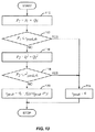
瞬時PDP生成回路60及び切替制御ロジック50の機能に戻って、一般に、n番目の活動期間又は測定期間に対するシングル・アンテナ受信機の瞬時PDPは以下の式となる。
![]()

![]()
![]()
![]()
![]()
![]()
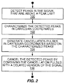
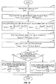
式(1)に見られるように、(複素数である)受信信号サンプルと適切に遅延された拡散符号との間の相関値が計算され(ブロック82)、相関値が位相コヒーレントに累積され(ブロック84)、これらがサンプルの数Ncの回数(内側の和)行われる(ブロック86)。位相コヒーレンスは弱め合い位相干渉を避けるために必要となる。しかしながら、チャネル状況の急速な変化に起因して、相関値は短い期間にコヒーレント累積されるだけとなりうる。その後、連続したコヒーレント累積値は、それぞれの遅延の電力値を生成するために、数NNCの回数(外側の和)をノンコヒーレントに累積される(ブロック88)。この処理は瞬時電力プロファイルを構築するために、対象の遅延値のすべてに対して繰り返され(ブロック92)、この時点で活動期間が終了する(ブロック94)。 As seen in equation (1), the correlation value between the received signal sample (which is a complex number) and the appropriately delayed spreading code is calculated (block 82) and the correlation values are accumulated in a phase coherent manner (block 84) These are performed the number of samples Nc (inner sum) (block 86). Phase coherence is needed to avoid destructive phase interference. However, due to rapid changes in channel conditions, correlation values can only be coherently accumulated in a short period of time. Subsequently, successive coherent accumulation values are accumulated non-coherently for a number N NC times (outer sum) to generate a power value for each delay (block 88). This process is repeated for all of the subject delay values to build an instantaneous power profile (block 92), at which point the active period ends (block 94).
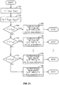
本発明によれば、切替制御ロジック50は瞬時PDP生成回路60の相関値のコヒーレント累積のために受信機フロントエンド回路42、44のどちらか一方からサンプルを選択するように切替回路に動的に命令する。数学的にこれが意味するところは、マルチパス・アンテナのPDPを計算する場合に、式(1)のアンテナ・インデックスはノンコヒーレント項のインデックスiの以下の関数であるということである。
切替関数f(i)は実装固有であり、プログラム可能であってもよく、従って動的であってもよい。関数f(i)は、コヒーレントに累積するためのCPICHシンボルの数NC、ノンコヒーレントに累積するためのコヒーレント累積値の数NNC、アンテナ切替の数及びタイミング、並びに送信速度のような他の要因を含む様々な要因を考慮してもよい。いくつかの経験則が切替関数f(i)に関して観察されるだろう。一般に、同一の総測定期間に対して、NCが大きいほど良好なPDP品質を生み出す。しかしながら、高速送信機(例えば、乗物内の移動体端末)においてNCを非常に大きくすることは出来ない。アンテナ切替は理想的には可能な限り頻繁に行われるべきである。しかしながら、それぞれの切替インスタンスにより生じるデータのわずかな欠損は切替周波数の上限を与える。当業者は、任意の所与の実装に対して、頻繁にアンテナを切り替えることの利益と、切替が招くデータ・ロスとの間の適切なバランスを突き止めることができるだろう。 The switching function f (i) is implementation specific and may be programmable and thus dynamic. The function f (i) depends on the number of CPICH symbols N C for coherent accumulation, the number N NC of coherent accumulation values for non-coherent accumulation, the number and timing of antenna switching, and other factors such as transmission rate. Various factors including factors may be considered. Several heuristics will be observed for the switching function f (i). In general, a larger N C yields better PDP quality for the same total measurement period. However, high-speed transmitter (e.g., a mobile terminal in a vehicle) can not be very large N C at. Antenna switching should ideally occur as often as possible. However, a slight loss of data caused by each switching instance gives an upper limit on the switching frequency. Those skilled in the art will be able to determine the appropriate balance between the benefits of frequent antenna switching and the data loss that switching incurs for any given implementation.
一つの制限は、アンテナ切替はNC個のシンボルの倍数において行われなければならないということである。つまり、切替点はコヒーレント結合の境界に調整されなければならず、任意の進行中のコヒーレント結合期間の間には発生しない。さらに、PDPの計算において十分なダイバーシチ利得を獲得するために、アンテナ切替はパス探索活動ごとに少なくとも一度行われるべきである。本発明の少なくとも一つの実施形態の十分な利点は、切替関数f(i)自体は動的であり、状況を根拠として変わってもよいことである。当業者は、切替制御ロジック50はコントローラ32で実行するソフトウェアとして実装されてもよく、従って仮想的に制限のない様々な切替周波数及び切替パターンが可能であることを直ちに認識するだろう。
One limitation is that antenna switching must be done in multiples of N C symbols. That is, the switch point must be adjusted to the coherent coupling boundary and does not occur during any ongoing coherent coupling period. In addition, antenna switching should be performed at least once per path search activity to obtain sufficient diversity gain in the PDP calculation. A sufficient advantage of at least one embodiment of the present invention is that the switching function f (i) itself is dynamic and may change based on the situation. Those skilled in the art will immediately recognize that the switching
いくつかの実装では、すべての受信機アンテナが同じ信号品質を提供するわけではない。計算されたPDPにおけるSNRの劣化を避けるために、それぞれの入力項は結果のSNRを最大化するようにアンテナ固有の重み係数w(a)により重み付けされてもよい。それぞれのアンテナに対する重み値w(a)は固定されてもよいし、動的に判定されてもよい。 In some implementations, not all receiver antennas provide the same signal quality. In order to avoid SNR degradation in the calculated PDP, each input term may be weighted by an antenna specific weighting factor w (a) to maximize the resulting SNR. The weight value w (a) for each antenna may be fixed or determined dynamically.
フェージングの影響を軽減するために、瞬時PDPのフィルタリングが当該技術で知られている様々な方法で達成されてもよい。ある実施形態では、フィルタリングは以下の式の指数平滑法により達成されてもよい。
![]()
![]()
αの値はシングル・アンテナ構成について適切なものよりも十分に低く、それによって遅延値の変化のトラッキングを改良する。 The value of α is well below that appropriate for a single antenna configuration, thereby improving the tracking of changes in delay values.
本発明のロジック、回路、及び方法によれば、PDPの生成はデュアル・アンテナ構成の多くの利益を獲得するが、シングル・アンテナ構成に要求されるハードウェア・リソースしか要求しない。主な利益は受信ダイバーシチ利得である(深いフェージングの可能性が軽減される)。RSCP及びRSSIについて報告するUE測定に直接的に用いられてもよい瞬時PDPは、すべてのアンテナ・ブランチからの最新の情報を合併する。フェージングの影響を軽減するのに必要なPDPのフィルタリングがより少なくなり、パス遅延の変化のより良いトラッキングが可能となる。切替関数f(i)は調整可能であり、異なるアンテナ・ブランチが異なる信号品質を有していたとしても最適な組み合わせを維持するように、重みを含んでいてもよい。特に、f(i)はフェージング処理の速度を合わせるように調整されてもよい。 In accordance with the logic, circuit and method of the present invention, the generation of a PDP obtains many benefits of a dual antenna configuration, but only requires the hardware resources required for a single antenna configuration. The main benefit is receive diversity gain (reducing the possibility of deep fading). Instantaneous PDP, which may be used directly for UE measurements reporting on RSCP and RSSI, merges the latest information from all antenna branches. Less PDP filtering is required to mitigate the effects of fading and better tracking of path delay changes is possible. The switching function f (i) is adjustable and may include weights so as to maintain an optimal combination even if different antenna branches have different signal qualities. In particular, f (i) may be adjusted to match the speed of the fading process.
本発明はパス探索の文脈で説明されてきたが、当業者はセル探索機能にも等しく適用可能であることを認識するだろう。これらの間の原理上の違いは、遅延d(t)の範囲とcmに組み込まれた基準スクランブル符号とだけである。どちらの場合においてもダイバーシチ利得は等しく適用可能であり、有利である。さらに、発明に係る受信機回路及び機能は移動体端末12で説明されてきたが、有利には、受信機は、BTS/RBS10のようなその他の無線アクセス・ネットワーク(RAN)のエンティティに配置されてもよい。
Although the present invention has been described in the context of path search, those skilled in the art will recognize that it is equally applicable to cell search functions. The only difference in principle between these is the range of delay d (t) and the reference scramble code embedded in cm . In either case, the diversity gain is equally applicable and advantageous. Furthermore, although the receiver circuit and functions according to the invention have been described in the
本明細書で用いられるように、“瞬時PDP”という用語はPDP生成回路60の一つの活動期間に生成された電力遅延プロファイル(すなわち、相関値のコヒーレント累積値についてのノンコヒーレント累積値)を表し、一つの活動期間の間に利用可能な情報を反映する。ある実施形態では、活動期間は一つ又は少数のWCDMAタイムスロットごとであってもよい。本明細書で用いられるように、“平均PDP”という用語は平均PDP計算回路62により出力されたフィルタ済みのPDPを表し、より長い間隔にわたって瞬時PDPを累積する。ある実施形態では、平均PDPは数個又は数十個のWCDMAフレームにわたって計算されてもよい。本明細書で用いられるように、アンテナパスとサンプルの変数との少なくとも何れかを“動的に”選択するという用語は、適用的な選択、すなわち変化する状況及びパラメータに基づく選択を表し、決定は一つの累積値から次の累積値にかけて変化してもよい(し、変化しなくてもよい)。 As used herein, the term “instantaneous PDP” refers to the power delay profile generated during one active period of the PDP generation circuit 60 (ie, the non-coherent cumulative value for the coherent cumulative value of the correlation value). Reflect information available during one activity period. In some embodiments, the activity period may be every one or a few WCDMA time slots. As used herein, the term “average PDP” refers to the filtered PDP output by the average PDP calculation circuit 62 and accumulates the instantaneous PDP over a longer interval. In some embodiments, the average PDP may be calculated over several or tens of WCDMA frames. As used herein, the term “dynamically” selecting at least one of an antenna path and a sample variable represents an application choice, ie a choice based on changing circumstances and parameters, and is determined. May change from one cumulative value to the next (or may not change).
本発明はもちろん、本発明の不可欠な特徴から逸脱せずに明細書で特定されたもの以外の方法で実行されてもよい。本実施形態はすべての観点で例示的であり制限的ではないとみなされるべきであり、添付の請求の範囲の意義と均等な範囲とから生じるすべての変更はこれに包含されることを意図する。 The present invention may, of course, be carried out in other ways than those specified in the specification without departing from the essential characteristics of the invention. The embodiments are to be considered in all respects as illustrative and not restrictive, and all modifications resulting from the meaning and equivalent scope of the appended claims are intended to be embraced therein .
RAKE受信機は熊手(rake)のような見かけからその名前が由来し、複数の平行な受信機のフィンガがそれぞれマルチパス信号を受信する。各フィンガには拡散符号の参照用コピー(reference copy)が提供され、これは対応するマルチパス成分のパス遅延と等しく遅延される。フィンガの出力はその後にコヒーレントに結合されてシンボル推定値を生成する。このように、RAKE受信機は受信マルチパス信号の信号対雑音比(SNR)を改善するためにマルチパス受信を利用する。RAKE受信機の性能は、すべてのパスからの信号エネルギーが利用される場合に最適化される。適切に遅延した拡散符号を各フィンガに提供するために、RAKE受信機はすべてのパスに対するマルチパス遅延の知識とチャネル・インパルス応答の値とを要求する。 The name of the RAKE receiver is derived from an appearance like a rake, and fingers of a plurality of parallel receivers each receive a multipath signal. Each finger is provided with a reference copy of the spreading code, which is delayed equal to the path delay of the corresponding multipath component. The finger outputs are then coherently combined to produce a symbol estimate. Thus, the RAKE receiver utilizes multipath reception to improve the signal to noise ratio (SNR) of the received multipath signal. The performance of the RAKE receiver is optimized when signal energy from all paths is utilized . A spreading code applied has earnestly delayed in order to provide for each finger, RAKE receiver requires the value of the knowledge and the channel impulse response of the multipath delay for all paths.
シングル・アンテナの受信機と同様に、デュアル・アンテナのRAKE受信機はマルチパス遅延の知識を要求する。移動体端末では、受信機アンテナの分離間隔は十分に小さいので、送信アンテナから両方の受信機アンテナへの基礎をなす遅延プロファイルは同一となる。従って、PDPを産出するのに一つのアンテナ入力信号だけが使用されるシングル・アンテナの受信機に適する動作と同じパス探索動作を原理上は利用できる。このPDPを長期間で平均した又はフィルタしたバージョンは、両方のアンテナ・ブランチに適用できるだろう。その一方で、二つの受信アンテナからの二つの(ほとんど)独立に弱まった入力信号の利用可能性は、パスについての深いフェードの可能性を効果的に減少することを可能とする。つまり、所与の瞬間において不可視である所与のパスに対して、両方のアンテナにおいて同時に弱まるにちがいない。結果として、一つのアンテナだけにおけるフェードよりも十分に低くなる可能性を有する。従って、両方のアンテナが利用される場合、瞬時PDPの強いフィルタリングは必要なく、パス遅延の動的トラッキングが向上するかもしれない。
ボンホフによる米国特許出願公開第2004/024047号明細書はPDPの計算に関する一つのアプローチを開示し、複数のアンテナの文脈を含む。ボンホフによれば、選択的に制御可能なコヒーレント累積ユニットが一つ以上のアンテナに対してPDPを産出する。このような処理は、受信信号パスを判定するために、振幅近似値で分類された閾値と(対応する)PDP部分とをRAKE受信機のような装置に伝える工程を含み得る。この文脈で、PDPのそれぞれは振幅近似の後にノンコヒーレントに累積されてもよい。
さらに、フランクらによる米国特許第6,731,622号明細書はCDMA信号送信の電力遅延スペクトラム(DPS)の判定に関する示唆を提供する。少なくとも一つの形態で、フランクの発明は、複数の音声チャネルに対する電力遅延プロファイルの生成について、個々の遅延パス選択を改善することを目的とする。上述のボンホフの出願と同様に、フランクの発明はマルチアンテナの電力遅延プロファイル処理を含む示唆を提供する。
Like a single antenna receiver, a dual antenna RAKE receiver requires knowledge of multipath delay. In a mobile terminal, the separation interval between receiver antennas is sufficiently small so that the underlying delay profile from the transmitting antenna to both receiver antennas is the same. Thus, in principle, the same path search operation as that suitable for a single antenna receiver where only one antenna input signal is used to produce a PDP can be used. A long-term averaged or filtered version of this PDP would be applicable to both antenna branches. On the other hand, the availability of two (almost) independently weakened input signals from the two receive antennas makes it possible to effectively reduce the possibility of deep fades on the path. That is, for a given path that is invisible at a given moment, both antennas must be weakened simultaneously. As a result, it has the potential to be much lower than a fade with only one antenna. Therefore, when both antennas are used, strong filtering of the instantaneous PDP is not necessary and dynamic tracking of the path delay may be improved.
U.S. Patent Application Publication No. 2004/024047 by Bonhof discloses one approach for the calculation of PDP and includes the context of multiple antennas. According to Bonhof, a selectively controllable coherent accumulation unit produces a PDP for one or more antennas. Such processing may include communicating thresholds classified by amplitude approximation and (corresponding) PDP portion to a device such as a RAKE receiver to determine a received signal path. In this context, each of the PDPs may be accumulated non-coherently after the amplitude approximation.
In addition, US Pat. No. 6,731,622 by Frank et al. Provides suggestions for determining the power delay spectrum (DPS) of CDMA signal transmission. In at least one form, Frank's invention aims to improve individual delay path selection for the generation of power delay profiles for multiple voice channels. Similar to the Bonhof application mentioned above, Frank's invention provides suggestions including multi-antenna power delay profile processing.
Claims (19)
第1のアンテナ及び第2のアンテナから既知のシンボル列を含んでいるパイロット信号を受信する工程と、
同一の活動期間内に変数NNCの回数の間、
処理するために前記第1のアンテナ又は前記第2のアンテナの何れかから変数NC個のパイロット信号のサンプルを動的に選択する工程と、
前記選択されたサンプルの相関結果のコヒーレント累積値を計算する工程と、
前記NNC個のコヒーレント累積値をノンコヒーレントに累積することによって瞬時PDPを計算する工程と
を含む方法。 A method for calculating a power density profile (PDP) comprising:
Receiving a pilot signal including a known symbol sequence from a first antenna and a second antenna;
For the number of variables N NC within the same activity period,
Dynamically selecting variable N C pilot signal samples from either the first antenna or the second antenna for processing;
Calculating a coherent cumulative value of a correlation result of the selected sample;
Method comprising the step of calculating the instantaneous PDP by accumulating the N NC number of coherent accumulations values in non-coherent.
前記それぞれのアンテナの信号品質に応じて、前記第1のアンテナ及び前記第2のアンテナからのサンプルのコヒーレント累積値に結合される重みを割当てる工程と、
前記NNC個の重み付けされたコヒーレント累積値をノンコヒーレントに累積する工程と
を含むことを特徴とする請求項1に記載の方法。 The step of dynamically accumulating the N NC coherent accumulation values includes:
Allocating weights coupled to coherent cumulative values of samples from the first antenna and the second antenna in accordance with the signal quality of the respective antennas;
The method according to claim 1, characterized in that a step of accumulating the N NC number of weighted coherent cumulative value in non-coherent.
第1のアンテナ及び第1の受信機フロントエンド回路を含む第1の信号受信パスと、
第2のアンテナ及び第2の受信機フロントエンド回路を含む第2の信号受信パスと、
受信パイロット信号に基づいて複数の遅延値に対して瞬時PDPを計算するように動作する電力密度プロファイル(PDP)生成回路と、
前記第1の信号受信パス又は前記第2の信号受信パスの何れかから前記PDP計算回路に信号のサンプルを導くように動作する切替回路と、
前記第1の信号受信パス又は前記第2の信号受信パスの何れかから変数NC個のサンプルを動的に選択するように前記切替回路に命令する切替制御ロジックと
を備える受信機。 A receiver,
A first signal receiving path including a first antenna and a first receiver front-end circuit;
A second signal receiving path including a second antenna and a second receiver front-end circuit;
A power density profile (PDP) generation circuit that operates to calculate an instantaneous PDP for a plurality of delay values based on a received pilot signal;
A switching circuit that operates to guide signal samples from either the first signal reception path or the second signal reception path to the PDP calculation circuit;
And a switching control logic that instructs the switching circuit to dynamically select a variable N C samples from either the first signal receiving path or the second signal receiving path.
前記切替回路は前記第1の信号受信パスと前記第2の信号受信パスと前記第3の信号受信パスとから選択するように動作し、
前記切替制御ロジックは、前記第1の信号受信パスと前記第2の信号受信パスと前記第3の信号受信パスとから変数NC個のサンプルを動的に選択するように前記切替回路に命令するように動作する
ことを特徴とする請求項12に記載の受信機。 A third signal receiving path including a third antenna and a third receiver front-end circuit;
The switching circuit operates to select from the first signal reception path, the second signal reception path, and the third signal reception path;
The switching control logic instructs the switching circuit to dynamically select variable N C samples from the first signal receiving path, the second signal receiving path, and the third signal receiving path. The receiver of claim 12, wherein the receiver operates.
第1の受信機フロントエンド回路に接続して動作する第1のアンテナと、
第2の受信機フロントエンド回路に接続して動作する第2のアンテナと、
受信パイロット信号に基づいて複数の遅延値に対して瞬時PDPを計算するように動作する電力密度プロファイル(PDP)生成回路と、
前記第1の受信機フロントエンド回路又は前記第2の受信機フロントエンド回路の何れかから前記PDP計算回路に信号のサンプルを導くように動作する切替回路と、
前記第1の信号受信パス又は前記第2の信号受信パスの何れかから変数NC個のサンプルを動的に選択するように前記切替回路に命令する切替制御ロジックと
を備える移動体端末。 A mobile terminal of a wireless communication system,
A first antenna operating in connection with a first receiver front-end circuit;
A second antenna operating in connection with a second receiver front end circuit;
A power density profile (PDP) generation circuit that operates to calculate an instantaneous PDP for a plurality of delay values based on a received pilot signal;
A switching circuit that operates to direct a sample of a signal from either the first receiver front-end circuit or the second receiver front-end circuit to the PDP calculation circuit;
A mobile terminal comprising switching control logic that instructs the switching circuit to dynamically select a variable N C samples from either the first signal receiving path or the second signal receiving path.
Applications Claiming Priority (5)
| Application Number | Priority Date | Filing Date | Title |
|---|---|---|---|
| US11/614,622 | 2006-12-21 | ||
| US11/614,622 US7724808B2 (en) | 2006-12-21 | 2006-12-21 | Efficient delay profile computation with receive diversity |
| US11/675,214 US20080151969A1 (en) | 2006-12-21 | 2007-02-15 | Efficient Delay Profile Computation with Receive Diversity |
| US11/675,214 | 2007-02-15 | ||
| PCT/EP2007/062087 WO2008074571A1 (en) | 2006-12-21 | 2007-11-08 | Efficient delay profile computation with receive diversity |
Publications (2)
| Publication Number | Publication Date |
|---|---|
| JP2010514295A true JP2010514295A (en) | 2010-04-30 |
| JP2010514295A5 JP2010514295A5 (en) | 2010-12-24 |
Family
ID=38929822
Family Applications (1)
| Application Number | Title | Priority Date | Filing Date |
|---|---|---|---|
| JP2009541937A Pending JP2010514295A (en) | 2006-12-21 | 2007-11-08 | Calculation of effective delay profile for receive diversity |
Country Status (4)
| Country | Link |
|---|---|
| US (1) | US20080151969A1 (en) |
| EP (1) | EP2095523A1 (en) |
| JP (1) | JP2010514295A (en) |
| WO (1) | WO2008074571A1 (en) |
Families Citing this family (2)
| Publication number | Priority date | Publication date | Assignee | Title |
|---|---|---|---|---|
| CN101682389B (en) * | 2007-05-29 | 2013-07-10 | 三菱电机株式会社 | Digital broadcast receiver |
| US8565686B2 (en) | 2011-06-30 | 2013-10-22 | Sprint Communications Company L.P. | Power status multipath search window sizing for wireless communications |
Citations (4)
| Publication number | Priority date | Publication date | Assignee | Title |
|---|---|---|---|---|
| JP2002514032A (en) * | 1998-05-01 | 2002-05-14 | テレフオンアクチーボラゲット エル エム エリクソン(パブル) | Search Window Delay Tracking in Code Division Multiple Access Communication Systems |
| JP2002517938A (en) * | 1998-05-29 | 2002-06-18 | テレフオンアクチーボラゲツト エル エム エリクソン(パブル) | Multipath propagation delay determination device using periodically inserted pilot symbols |
| JP2003143036A (en) * | 2001-11-01 | 2003-05-16 | Toshiba Corp | Path search method and receiver in direct sequence spread spectrum communication |
| JP2006520133A (en) * | 2003-03-05 | 2006-08-31 | インターディジタル テクノロジー コーポレイション | Wireless transceiver unit and method for processing received signals for wireless communication |
Family Cites Families (7)
| Publication number | Priority date | Publication date | Assignee | Title |
|---|---|---|---|---|
| JP2751910B2 (en) * | 1996-02-28 | 1998-05-18 | 日本電気株式会社 | Semiconductor light receiving element and method of manufacturing the same |
| US6731622B1 (en) * | 1998-05-01 | 2004-05-04 | Telefonaktiebolaget Lm Ericsson (Publ) | Multipath propagation delay determining means using periodically inserted pilot symbols |
| FI19992734A (en) * | 1999-12-20 | 2001-06-21 | Nokia Networks Oy | A method for receiving a spread spectrum signal and a receiver |
| DE10157535B4 (en) * | 2000-12-13 | 2015-05-13 | Jörg Houpert | Method and apparatus for reducing random, continuous, transient disturbances in audio signals |
| JP2004289191A (en) * | 2001-01-19 | 2004-10-14 | Yozan Inc | Path search method and receiver in ds-cdma system |
| JP2003338804A (en) * | 2002-05-22 | 2003-11-28 | Nec Corp | Path search apparatus and method, and antenna array receiving apparatus using the same |
| DE10345959B4 (en) * | 2003-10-02 | 2005-12-15 | Infineon Technologies Ag | Operational situation-dependent identification and selection of the transmission paths for the establishment of rake fingers of Rake receiver units in mobile communication terminals |
-
2007
- 2007-02-15 US US11/675,214 patent/US20080151969A1/en not_active Abandoned
- 2007-11-08 EP EP07822389A patent/EP2095523A1/en not_active Withdrawn
- 2007-11-08 JP JP2009541937A patent/JP2010514295A/en active Pending
- 2007-11-08 WO PCT/EP2007/062087 patent/WO2008074571A1/en active Application Filing
Patent Citations (4)
| Publication number | Priority date | Publication date | Assignee | Title |
|---|---|---|---|---|
| JP2002514032A (en) * | 1998-05-01 | 2002-05-14 | テレフオンアクチーボラゲット エル エム エリクソン(パブル) | Search Window Delay Tracking in Code Division Multiple Access Communication Systems |
| JP2002517938A (en) * | 1998-05-29 | 2002-06-18 | テレフオンアクチーボラゲツト エル エム エリクソン(パブル) | Multipath propagation delay determination device using periodically inserted pilot symbols |
| JP2003143036A (en) * | 2001-11-01 | 2003-05-16 | Toshiba Corp | Path search method and receiver in direct sequence spread spectrum communication |
| JP2006520133A (en) * | 2003-03-05 | 2006-08-31 | インターディジタル テクノロジー コーポレイション | Wireless transceiver unit and method for processing received signals for wireless communication |
Also Published As
| Publication number | Publication date |
|---|---|
| WO2008074571A1 (en) | 2008-06-26 |
| US20080151969A1 (en) | 2008-06-26 |
| EP2095523A1 (en) | 2009-09-02 |
Similar Documents
| Publication | Publication Date | Title |
|---|---|---|
| JP5575859B2 (en) | Received signal prediction system and method in a wireless communication system | |
| KR100822940B1 (en) | System and method for adjusting combiner weights using an adaptive algorithm in a wireless communication system | |
| JP4444961B2 (en) | Determining the channel rating of a transmission channel | |
| TWI389485B (en) | Method and system for achieving space and time diversity gain | |
| JP4504567B2 (en) | Apparatus and method for performing signal search in a coherent wireless communication system | |
| JP2009260968A6 (en) | Received signal prediction system and method in a wireless communication system | |
| US6615030B1 (en) | Mobile communications system and radio base station apparatus | |
| JPH09181664A (en) | Radio subscriber unit having changeover antenna diversity device and its method | |
| JPH09181666A (en) | Method for controlling diversity receiver in radio subscriber unit | |
| JPH09181665A (en) | Dual mode radio subscriber unit having diversity receiver and its method | |
| KR20080078648A (en) | Efficient cell selection | |
| JP4823469B2 (en) | Smart antenna using adaptive convergence parameters | |
| US20070189362A1 (en) | Method and system for channel estimation, related receiver and computer program product | |
| US7724808B2 (en) | Efficient delay profile computation with receive diversity | |
| JP2002084216A (en) | Array antenna wireless communication unit | |
| US7450556B2 (en) | Method and apparatus estimating cell interference and noise for CDMA packet data channels | |
| KR100504360B1 (en) | Receiver and reception method | |
| JP2010514295A (en) | Calculation of effective delay profile for receive diversity | |
| JP4554682B2 (en) | System and method for reducing rake finger processing | |
| JPH10271034A (en) | Cdma mobile communication receiver | |
| JP4971303B2 (en) | Method for selecting a delay value for a RAKE receiver | |
| JP2002261658A (en) | Receiving apparatus and pass selection method | |
| JP4266826B2 (en) | Data transmission method and receiver | |
| KR20020039424A (en) | High Performance Space-Time Array Receive System and Method Using Fading Rate Indicator | |
| JP2002353857A (en) | Rake receiver and rake reception method |
Legal Events
| Date | Code | Title | Description |
|---|---|---|---|
| A521 | Request for written amendment filed |
Free format text: JAPANESE INTERMEDIATE CODE: A523 Effective date: 20101101 |
|
| A621 | Written request for application examination |
Free format text: JAPANESE INTERMEDIATE CODE: A621 Effective date: 20101101 |
|
| A977 | Report on retrieval |
Free format text: JAPANESE INTERMEDIATE CODE: A971007 Effective date: 20120831 |
|
| A131 | Notification of reasons for refusal |
Free format text: JAPANESE INTERMEDIATE CODE: A131 Effective date: 20121001 |
|
| A521 | Request for written amendment filed |
Free format text: JAPANESE INTERMEDIATE CODE: A523 Effective date: 20121221 |
|
| A02 | Decision of refusal |
Free format text: JAPANESE INTERMEDIATE CODE: A02 Effective date: 20130322 |