JP2010513962A - Method and apparatus for reducing speckle - Google Patents
Method and apparatus for reducing speckle Download PDFInfo
- Publication number
- JP2010513962A JP2010513962A JP2009541955A JP2009541955A JP2010513962A JP 2010513962 A JP2010513962 A JP 2010513962A JP 2009541955 A JP2009541955 A JP 2009541955A JP 2009541955 A JP2009541955 A JP 2009541955A JP 2010513962 A JP2010513962 A JP 2010513962A
- Authority
- JP
- Japan
- Prior art keywords
- reconstruction
- light
- scene
- optical
- slm
- Prior art date
- Legal status (The legal status is an assumption and is not a legal conclusion. Google has not performed a legal analysis and makes no representation as to the accuracy of the status listed.)
- Pending
Links
- 238000000034 method Methods 0.000 title claims abstract description 35
- 230000003287 optical effect Effects 0.000 claims abstract description 41
- 230000001427 coherent effect Effects 0.000 claims abstract description 25
- 238000005286 illumination Methods 0.000 claims abstract description 25
- 230000008859 change Effects 0.000 claims description 11
- 239000013307 optical fiber Substances 0.000 claims description 9
- 230000001131 transforming effect Effects 0.000 claims description 2
- 230000015572 biosynthetic process Effects 0.000 claims 1
- 238000003786 synthesis reaction Methods 0.000 claims 1
- 230000009467 reduction Effects 0.000 abstract description 9
- 238000006243 chemical reaction Methods 0.000 description 10
- 230000000694 effects Effects 0.000 description 5
- 238000012935 Averaging Methods 0.000 description 4
- 210000001747 pupil Anatomy 0.000 description 4
- 230000008901 benefit Effects 0.000 description 3
- 239000002131 composite material Substances 0.000 description 3
- 238000010586 diagram Methods 0.000 description 3
- 238000009826 distribution Methods 0.000 description 2
- 239000011521 glass Substances 0.000 description 2
- 238000001093 holography Methods 0.000 description 2
- 230000008569 process Effects 0.000 description 2
- 230000002123 temporal effect Effects 0.000 description 2
- 230000009466 transformation Effects 0.000 description 2
- 230000002411 adverse Effects 0.000 description 1
- 239000000969 carrier Substances 0.000 description 1
- 230000007423 decrease Effects 0.000 description 1
- 230000001419 dependent effect Effects 0.000 description 1
- 238000001514 detection method Methods 0.000 description 1
- 238000009792 diffusion process Methods 0.000 description 1
- 239000006185 dispersion Substances 0.000 description 1
- 238000006073 displacement reaction Methods 0.000 description 1
- 239000011159 matrix material Substances 0.000 description 1
- 230000000737 periodic effect Effects 0.000 description 1
- 230000004044 response Effects 0.000 description 1
- 238000001228 spectrum Methods 0.000 description 1
Images
Classifications
-
- G—PHYSICS
- G03—PHOTOGRAPHY; CINEMATOGRAPHY; ANALOGOUS TECHNIQUES USING WAVES OTHER THAN OPTICAL WAVES; ELECTROGRAPHY; HOLOGRAPHY
- G03H—HOLOGRAPHIC PROCESSES OR APPARATUS
- G03H1/00—Holographic processes or apparatus using light, infrared or ultraviolet waves for obtaining holograms or for obtaining an image from them; Details peculiar thereto
- G03H1/32—Systems for obtaining speckle elimination
-
- G—PHYSICS
- G03—PHOTOGRAPHY; CINEMATOGRAPHY; ANALOGOUS TECHNIQUES USING WAVES OTHER THAN OPTICAL WAVES; ELECTROGRAPHY; HOLOGRAPHY
- G03H—HOLOGRAPHIC PROCESSES OR APPARATUS
- G03H1/00—Holographic processes or apparatus using light, infrared or ultraviolet waves for obtaining holograms or for obtaining an image from them; Details peculiar thereto
- G03H1/22—Processes or apparatus for obtaining an optical image from holograms
- G03H1/2286—Particular reconstruction light ; Beam properties
-
- G—PHYSICS
- G03—PHOTOGRAPHY; CINEMATOGRAPHY; ANALOGOUS TECHNIQUES USING WAVES OTHER THAN OPTICAL WAVES; ELECTROGRAPHY; HOLOGRAPHY
- G03H—HOLOGRAPHIC PROCESSES OR APPARATUS
- G03H1/00—Holographic processes or apparatus using light, infrared or ultraviolet waves for obtaining holograms or for obtaining an image from them; Details peculiar thereto
- G03H1/22—Processes or apparatus for obtaining an optical image from holograms
- G03H1/2294—Addressing the hologram to an active spatial light modulator
-
- G—PHYSICS
- G03—PHOTOGRAPHY; CINEMATOGRAPHY; ANALOGOUS TECHNIQUES USING WAVES OTHER THAN OPTICAL WAVES; ELECTROGRAPHY; HOLOGRAPHY
- G03H—HOLOGRAPHIC PROCESSES OR APPARATUS
- G03H1/00—Holographic processes or apparatus using light, infrared or ultraviolet waves for obtaining holograms or for obtaining an image from them; Details peculiar thereto
- G03H1/22—Processes or apparatus for obtaining an optical image from holograms
- G03H1/2286—Particular reconstruction light ; Beam properties
- G03H2001/2289—Particular reconstruction light ; Beam properties when reconstruction wavelength differs form recording wavelength
-
- G—PHYSICS
- G03—PHOTOGRAPHY; CINEMATOGRAPHY; ANALOGOUS TECHNIQUES USING WAVES OTHER THAN OPTICAL WAVES; ELECTROGRAPHY; HOLOGRAPHY
- G03H—HOLOGRAPHIC PROCESSES OR APPARATUS
- G03H1/00—Holographic processes or apparatus using light, infrared or ultraviolet waves for obtaining holograms or for obtaining an image from them; Details peculiar thereto
- G03H1/22—Processes or apparatus for obtaining an optical image from holograms
- G03H1/2294—Addressing the hologram to an active spatial light modulator
- G03H2001/2297—Addressing the hologram to an active spatial light modulator using frame sequential, e.g. for reducing speckle noise
-
- G—PHYSICS
- G03—PHOTOGRAPHY; CINEMATOGRAPHY; ANALOGOUS TECHNIQUES USING WAVES OTHER THAN OPTICAL WAVES; ELECTROGRAPHY; HOLOGRAPHY
- G03H—HOLOGRAPHIC PROCESSES OR APPARATUS
- G03H1/00—Holographic processes or apparatus using light, infrared or ultraviolet waves for obtaining holograms or for obtaining an image from them; Details peculiar thereto
- G03H1/26—Processes or apparatus specially adapted to produce multiple sub- holograms or to obtain images from them, e.g. multicolour technique
- G03H1/2645—Multiplexing processes, e.g. aperture, shift, or wavefront multiplexing
- G03H2001/266—Wavelength multiplexing
-
- G—PHYSICS
- G03—PHOTOGRAPHY; CINEMATOGRAPHY; ANALOGOUS TECHNIQUES USING WAVES OTHER THAN OPTICAL WAVES; ELECTROGRAPHY; HOLOGRAPHY
- G03H—HOLOGRAPHIC PROCESSES OR APPARATUS
- G03H2222/00—Light sources or light beam properties
- G03H2222/10—Spectral composition
- G03H2222/13—Multi-wavelengths wave with discontinuous wavelength ranges
Abstract
本発明は、三次元ホログラフィック再構成のスペックルパターンの低減のための方法に関する。この方法によれば、その中へ三次元シーンのホログラムがコード化されるコントローラブルな光変調器(ISLM)がコヒーレント光で照射され、再構成レンズ(RO)が変調された光を目の位置(PE)へ変換し、再構成空間において三次元シーンを再構成し、制御手段(CM)はその照明を制御する。本発明の目的は、三次元シーンの再構成のはいだに生じるスペックルパターンが低減されるホログラフィック再構成装置を提供することにある。他の目的は、通常の画像リフレッシュレートを有するキャリア媒体を用いて、ほぼリアルタイムな方法を提供することにある。この目的のために、制御手段(7)は少なくとも一つの特性に関してコヒーレント光を操作する。例えば、異なる波長を有する複数の複素波面が光変調器を通り、エンコードされたホログラムで変調され、再構成レンズを通して目の位置へ変換され、再構成空間の同じ位置に同じ三次元シーンの複数の再構成を生成する。ここで、再構成は異なるスペックルパターンを有し、三次元シーンのスペックルが減少された単一の再構成として平均化される。 The present invention relates to a method for the reduction of speckle patterns in three-dimensional holographic reconstruction. According to this method, a controllable light modulator (ISLM) into which a hologram of a three-dimensional scene is coded is irradiated with coherent light, and the reconstructed lens (RO) is modulated with light. (PE), and the three-dimensional scene is reconstructed in the reconstruction space, and the control means (CM) controls the illumination. An object of the present invention is to provide a holographic reconstruction device in which a speckle pattern that occurs in the reconstruction of a three-dimensional scene is reduced. Another object is to provide a near real-time method using a carrier medium having a normal image refresh rate. For this purpose, the control means (7) manipulate the coherent light with respect to at least one characteristic. For example, multiple complex wavefronts with different wavelengths are passed through an optical modulator, modulated with an encoded hologram, converted to an eye position through a reconstruction lens, and multiple multiple of the same 3D scene at the same position in the reconstruction space Generate a reconstruction. Here, the reconstructions have different speckle patterns and are averaged as a single reconstruction with reduced speckle in the 3D scene.
Description
本発明は、3次元シーンの3次元ホログラフィック再構成における斑点或いは染みのようなパターン(以下、スペクルパターンという)を減少する方法に関する。また、その方法を実施するのに使用されるホログラフィックディスプレイ装置に関する。 The present invention relates to a method of reducing a pattern such as a spot or a stain (hereinafter referred to as a speckle pattern) in a three-dimensional holographic reconstruction of a three-dimensional scene. It also relates to a holographic display device used to implement the method.
本発明は、3次元シーンの複合波面を、ホログラフィの支援により記録し、再構成することを可能にする方法とともに適用され得る。好ましくは、これらは、ホログラフィックディスプレイ装置においてリアルタイムに或いは、ほぼリアルタイムにレーザ光を用いて実行される。ここで、再構成は仮想の観察ウインドウから見ることができる。 The invention can be applied with a method that allows a composite wavefront of a three-dimensional scene to be recorded and reconstructed with the aid of holography. Preferably, these are performed using laser light in real time or near real time in a holographic display device. Here, the reconstruction can be viewed from a virtual observation window.
ホログラフィは、3次元オブジェクト或いは動きのある3Dシーンを記録することを可能にし、また、波動光学的手法を用いて光学的に描写することを可能にする。3Dシーンは、キャリア媒体として機能する光変調器上にエンコードされる。干渉を生成することが可能な光波による照明によって、エンコードされた3Dシーンの各位置は、互いに干渉する光波の起点を形成し、結果的な光波面として、空間内の実オブジェクトから進む光によって生成されたかのような3Dシーンを空間的に再構成する。オブジェクト或いは3Dシーンのホログラフィック再構成は、好ましくは、投影装置及び/又は光再構成システムの支援で、キャリア媒体を十分にコヒーレントな光で照射することにより実現される。 Holography makes it possible to record 3D objects or moving 3D scenes and to optically describe them using wave optics techniques. The 3D scene is encoded on a light modulator that functions as a carrier medium. By illumination with light waves capable of generating interference, each position in the encoded 3D scene forms the origin of the light waves that interfere with each other, and as a result a light wavefront generated by light traveling from a real object in space Spatial reconstruction of the 3D scene as if it were done. Holographic reconstruction of the object or 3D scene is preferably achieved by illuminating the carrier medium with sufficiently coherent light with the aid of a projection device and / or a light reconstruction system.
本明細書において、3Dシーンは観察ウインドウを有するホログラフィックディスプレイ装置において再構成される。ここで、観察ウインドウは、再構成空間における再構成手段の後ろ側焦点面内に配置された複素波面(complex-valued wave front)の周期の間隔における可視領域である。3Dシーンの再構成は、観察者の左目及び/又は右目によって観察ウインドウから見ることができる。表示手段の前方にある観察ウインドウのサイズは、少なくとも瞳の大きさを有するように決定される。 Herein, the 3D scene is reconstructed in a holographic display device having an observation window. Here, the observation window is a visible region in a period interval of a complex-valued wave front arranged in the rear focal plane of the reconstruction means in the reconstruction space. The reconstruction of the 3D scene can be viewed from the viewing window by the viewer's left eye and / or right eye. The size of the observation window in front of the display means is determined so as to have at least the size of the pupil.
波動光学の観点から見ると、観察ウインドウは、キャリア媒体にエンコードされたホログラムの直接または逆フーリエ変換またはフレネル変換のいずれかによって、または、再構成空間においてキャリア媒体上にエンコードされた波面のイメージによって表される。ここで、観察ウインドウは周期的な再構成の1つの回折次数のみを備える。可視領域として用いられる1つの回折次数内で、観察ウインドウ内への他の回折次数のクロストークが防止されるように、ホログラムまたは波面は3Dシーンから計算される。そのようなクロストークは、一般に、光変調を用いる場合に、再構成において発生する。高次の回折次数を抑制する構成または方法と連動して、3Dシーンは、多重プロセスにおいて、クロストーク無しに、観察者の右眼及び左眼に連続的に提示され得る。更に、複数の人に提供することを目的とする多重化プロセスは、それによってのみ可能となる。 From a wave optics perspective, the observation window is either by direct or inverse Fourier transform or Fresnel transform of the hologram encoded on the carrier medium, or by an image of the wavefront encoded on the carrier medium in reconstruction space. expressed. Here, the observation window comprises only one diffraction order of periodic reconstruction. Within one diffraction order used as the visible region, the hologram or wavefront is calculated from the 3D scene so that crosstalk of other diffraction orders into the observation window is prevented. Such crosstalk generally occurs in reconstruction when using light modulation. In conjunction with a configuration or method that suppresses higher order diffraction orders, the 3D scene can be continuously presented to the viewer's right and left eyes in a multiplex process without crosstalk. Furthermore, a multiplexing process intended to serve multiple people is only possible thereby.
3Dシーンのホログラム及び複素波面のためのキャリア或いは記録媒体は、LCDやLCoSなどのような空間的な光変調器を含む。これらは、入射光の位相及び/又は振幅を変調する。キャリア媒体のリフレッシュ周期は、動きのある3Dシーンを再構成することができるように十分に高速でなければならない。
キャリア媒体上の規則正しいパターンに配置された画素へエンコードされる値は、実際のオブジェクトを起源としたものとすることもできるし、或いはコンピュータ合成ホログラム(CGH:computer-generated hologram)とすることもできる。
Carriers or recording media for 3D scene holograms and complex wavefronts include spatial light modulators such as LCD and LCoS. These modulate the phase and / or amplitude of the incident light. The refresh period of the carrier medium must be fast enough so that a moving 3D scene can be reconstructed.
The values encoded into the pixels arranged in a regular pattern on the carrier medium can originate from the actual object or can be a computer-generated hologram (CGH). .
観察者は、キャリア媒体を直接に見ることによって3Dシーンの再構成を観察することができる。本明細書において、この構成をダイレクトビュー表示と称する。或いは、観察者は、キャリア媒体にエンコードされた値のイメージ又は変換(transform)が投影されるスクリーンを見ることができる。本明細書において、この構成は投影表示と称する。
投影表示におけるスクリーンとダイレクトビュー表示におけるキャリア媒体の両方を総称して、以下ではスクリーンと称する。
An observer can observe the reconstruction of the 3D scene by looking directly at the carrier medium. In this specification, this configuration is referred to as direct view display. Alternatively, the viewer can see a screen on which the encoded value image or transform is projected onto the carrier medium. In this specification, this configuration is referred to as projection display.
Both the screen in the projection display and the carrier medium in the direct view display are collectively referred to as a screen below.
離散的な記録に起因して、及び、偏向の影響のせいで、ホログラムの再構成は波面の再構成の1つの時間間隔内においてのみ可能である。ここで、この時間間隔はキャリア媒体の解像度によって定まるものである。再構成は、典型的には、隣接する時間間隔に対して不揃いを示しながら、繰り返される。 Due to the discrete recording and due to the influence of deflection, the reconstruction of the hologram is only possible within one time interval of the reconstruction of the wavefront. Here, this time interval is determined by the resolution of the carrier medium. The reconstruction is typically repeated while showing irregularities with respect to adjacent time intervals.
スペックルパターン或いは粒状として知られているパターンの乱れは、光変調器を照明するためのコヒーレントなレーザ光を使用するときに発生する。スペックルは、粒状の干渉パターンとして説明され得る。これは、統計的に不揃いに分配された位相差を有する複数の光波の干渉により生成される。 Pattern disturbances known as speckle patterns or graininess occur when using coherent laser light to illuminate the light modulator. Speckle can be described as a granular interference pattern. This is generated by interference of a plurality of light waves having phase differences distributed statistically unevenly.
ホログラムの再構成は、スペックルパターンによって悪影響を受ける。3Dシーンはキャリア媒体に離散的にしか記録することができないため、3Dシーンはホログラム計算のために離散的にスキャンされる。キャリア媒体に適切な方法で3Dシーンを記録するエンコード方法は、スキャンポイントの位置においてスキャンされたオブジェクトと十分に一致する再構成を可能にする。物理的再構成は、スキャンポイント間においても連続的な階調となる。オブジェクトにおける光度勾配からの逸脱は、スキャンポイント間で発生し、再構成は、その品質を低下させる、スペックルパターンを露呈する。これは、特に、ランダムなオブジェクトポイントの位相でホログラムを計算するときに発生するが、それは、ある他の理由のために利点となる。 Hologram reconstruction is adversely affected by speckle patterns. Since 3D scenes can only be recorded discretely on a carrier medium, 3D scenes are scanned discretely for hologram calculations. An encoding method that records a 3D scene in a manner appropriate to the carrier medium allows reconstruction that matches well with the scanned object at the location of the scan point. The physical reconstruction is continuous gradation between scan points. Deviations from the light intensity gradient in the object occur between scan points, and the reconstruction exposes a speckle pattern that reduces its quality. This occurs especially when calculating holograms with random object point phases, which is advantageous for certain other reasons.
3Dシーンの再構成におけるスペックルパターンの低減は、時間的及び/又は空間的な平均化により実現される。ここで、再構成は、外部のキャリアメディア上にエンコードされた3Dシーンの値から、或いは、他の適切な方法で計算されたホログラム値から生成される。観察者の目は、常に提示されている複数の再構成を平均化しており、この障害のはっきりとした減少に帰結する。 The reduction of speckle patterns in 3D scene reconstruction is achieved by temporal and / or spatial averaging. Here, the reconstruction is generated from the values of the 3D scene encoded on the external carrier medium or from hologram values calculated in other suitable ways. The observer's eyes average out the multiple reconstructions that are always presented, resulting in a clear reduction in this disorder.
DE19541071A1によれば、ホログラムをチェックするときに粒状性を平均化するために回転する長方形のガラス板が光路上に置かれる。ガラス板が検出器の周期に適応する周期で回転するため、スペックルはもはや邪魔をしなくなる。しかしながら、そのような方法は、2次元の、平面的なスペックルパターンの減少に適用され得るのみであり、拡散スクリーンがスペックルパターンの面に配置されなければならない。
3Dシーンのスペックルパターンを減少するための時間的な平均化に関して知られている方法では、所定数の異なるランダムな位相で3Dシーンが計算され、ホログラムのそれぞれが、速いペースで次から次へとキャリア媒体上に描かれる。ホログラムの表示においては、多数回のホログラム計算のために計算負荷が非常に増加し、キャリア媒体のリフレッシュ頻度が非常に増加してしまう。これらは好ましくないことである。
According to DE19541071A1, a rotating rectangular glass plate is placed on the optical path in order to average the graininess when checking the hologram. As the glass plate rotates with a period that adapts to the period of the detector, the speckle no longer gets in the way. However, such a method can only be applied to the reduction of a two-dimensional, planar speckle pattern, and the diffusing screen has to be placed on the surface of the speckle pattern.
In known methods for temporal averaging to reduce the speckle pattern of a 3D scene, a 3D scene is calculated with a predetermined number of different random phases, and each of the holograms is fast-paced from one to the next. And drawn on the carrier medium. In the display of holograms, the calculation load is greatly increased due to many hologram calculations, and the frequency of refreshing the carrier medium is greatly increased. These are undesirable.
空間的な平均化に関しては、一般に、次のものが文献から知られている。すなわち、キャリア媒体を複数の独立したセクションに分割し、同じオブジェクトから算出されるが異なるオブジェクト位相を有するサブホログラムを、隣から隣へと、及び/又は下へ下へと繰り返し描いていく。観察者の目は、フーリエ変換またはフレネル変換で生成された、計算されたサブホログラムの個々の再構成の異なるスペックルパターンを平均化する。それにより、スペックルパターンが弱められたようにみえる。 As regards spatial averaging, the following are generally known from the literature: That is, the carrier medium is divided into a plurality of independent sections, and sub-holograms calculated from the same object but having different object phases are repeatedly drawn from next to next and / or down to the bottom. The observer's eye averages the different speckle patterns of the individual reconstructions of the calculated sub-holograms generated by the Fourier transform or Fresnel transform. As a result, the speckle pattern appears to have been weakened.
しかしながら、この方法は、本出願人によるDE10353439A1(本願はこの出願をベースとしている)に記載された観察ウインドウを用いるホログラフィックディスプレイには適用できない。例えば3Dシーンのような、オブジェクトの回折画像の複素配光は、観察ウインドウにおいて計算される。個々のオブジェクト平面の、3Dシーンが仮想的にスライスされる変換は、これを達成するために、観察ウインドウにおいて実現され、追加される。変換は、スライスされたオブジェクト平面と観察ウインドウを備える平面との間の光の光学的な伝播と一致する。この方法は、各オブジェクトのポイントが、このポイントの再構成のための情報が書き込まれる画面上の限定されローカライズされたセクションに割り当てられるという効果を有する。
スクリーン上において、隣り合う及び/又は下へ並ぶ、3Dシーンから計算された複数のサブホログラムのエンコードは、従来技術において示唆されるように、オブジェクトポイントに対応するホログラム値がスクリーン上の異なるセクションにおいて繰り返されるという効果を有する。これは、観察ウインドウから再構成された3Dシーンを可視にすることの原理に関して可能ではない。また、サブホログラムの空間的な繰り返しには、各個別サブホログラムの解像度がキャリア媒体において減少するという不具合がある。
However, this method is not applicable to holographic displays using the observation window described in the applicant's DE 10353439 A1 (which is based on this application). The complex light distribution of the diffracted image of the object, for example a 3D scene, is calculated in the observation window. A transformation in which the 3D scene of an individual object plane is virtually sliced is realized and added in the observation window to achieve this. The transformation is consistent with the optical propagation of light between the sliced object plane and the plane comprising the observation window. This method has the effect that each object point is assigned to a limited localized section on the screen where information for the reconstruction of this point is written.
The encoding of multiple sub-holograms calculated from 3D scenes side by side and / or down on the screen, as suggested in the prior art, the hologram values corresponding to the object points are in different sections on the screen. Has the effect of being repeated. This is not possible with respect to the principle of making the reconstructed 3D scene visible from the observation window. In addition, the spatial repetition of sub-holograms has the disadvantage that the resolution of each individual sub-hologram is reduced in the carrier medium.
本発明の目的は、仮想的な観察ウインドウを用いるホログラフィックディスプレイ装置において3Dシーンを再構成するときに発生するスペックルパターンを大きく減少すること、そして、一般的なリフレッシュ頻度を有するキャリア媒体が使用可能でありながらほぼリアルタイムな方法を提供することにある。 An object of the present invention is to greatly reduce the speckle pattern generated when reconstructing a 3D scene in a holographic display device using a virtual observation window, and to use a carrier medium having a general refresh frequency. It is to provide a near real-time method that is possible.
本発明は、3Dシーンのホログラムがエンコードされた、コントローラブルな光変調器が十分にコヒーレントな光で照明され、光再構成システムが変調された光を観察ウインドウ又は再構成空間における視点位置に変換して再構成空間に3Dシーンを再構成し、そして、制御手段によって照明が制御される方法に基づいている。
本発明が基礎としている、3Dシーンを再構成するための観察ウインドウは、エンコードされたホログラムの複素波面の、異なる光拡散が生成される再構成空間における位置としての視点位置と一致しているとみなすことができる。再構成された3Dシーンを見ることができるようにするために、観察者の目はその視点位置になければならない。
In the present invention, a controllable light modulator encoded with a hologram of a 3D scene is illuminated with sufficiently coherent light, and a light reconstruction system converts the modulated light into a viewing position in an observation window or reconstruction space. Based on the method in which the 3D scene is reconstructed in the reconstruction space and the lighting is controlled by the control means.
The observation window for reconstructing the 3D scene on which the present invention is based is coincident with the viewpoint position as the position in the reconstruction space where the different light diffusions of the complex wavefront of the encoded hologram are generated. Can be considered. In order to be able to see the reconstructed 3D scene, the viewer's eyes must be in their viewpoint position.
本発明によれば、以下の方法により目的が達成される。すなわち、異なる波長をもつ複数の複素波面が光変調器を通過してエンコードされたホログラム値で変調され、変調された複素波面は前記光再構成システム(RO)によって目の位置(PE)に変換され、再構成空間の同じ位置にわずかに異なるスペックルパターンをもって3Dシーンの複数の再構成を生成し、複数の再構成が目の位置(PE)から平均化されて3Dシーンのスペックルが減少された単一の再構成(RE)となるように、制御手段がコヒーレント光の少なくとも一つの特性に作用する。
光の波長に作用することにより、わずかに変更されたスペックルパターンをもつ、同一の3Dシーンの複数のわずかに変更された再構成が生成され得る。
According to the present invention, the object is achieved by the following method. That is, a plurality of complex wavefronts having different wavelengths are modulated with hologram values encoded through an optical modulator, and the modulated complex wavefronts are converted into eye positions (PE) by the optical reconstruction system (RO). Generate multiple reconstructions of the 3D scene with slightly different speckle patterns at the same location in the reconstruction space, and the multiple reconstructions are averaged from the eye position (PE) to reduce speckle in the 3D scene The control means acts on at least one characteristic of the coherent light so that a single reconfiguration (RE) is achieved.
By acting on the wavelength of light, multiple slightly modified reconstructions of the same 3D scene can be generated with slightly modified speckle patterns.
請求項2に記載された方法の一実施形態によれば、以下のステップが実行される。すなわち、
照明手段(L)が、制御手段(CM)により制御されて、光再構成システム(RO)と光変調器(SLM)とを照明するために、わずかずつ異なる波長をもつ高速ペースのコヒーレントな光のパルス列を生成し、
高速ペースの光のパルス列は光変調器(SLM)を通過し、そこで、光のパルスの複素波面がエンコードされたホログラム値で変調され、
変調された複素波面の高速ペースの列が再構成空間の目の位置(PE)に変換され、同じ3Dシーンの複数の再構成を、再構成空間の同じ位置に高速なペースで次々と生成する。
According to one embodiment of the method as claimed in claim 2, the following steps are performed. That is,
Fast-paced coherent light with slightly different wavelengths for illuminating means (L) controlled by control means (CM) to illuminate the optical reconstruction system (RO) and the light modulator (SLM) Generate a pulse train of
The fast paced light pulse train passes through a light modulator (SLM), where the complex wavefront of the light pulse is modulated with the encoded hologram value,
A fast-paced sequence of modulated complex wavefronts is converted to eye positions (PE) in the reconstruction space to generate multiple reconstructions of the same 3D scene one after another at the same position in the reconstruction space. .
請求項3において記載されたような、本発明の更なる実施形態によれば、上記の代わりに以下に示すような処理ステップを有し、上記と同じ結果を得ることができる。すなわち、
複数の照明手段が同時にコヒーレント光を放出し、それらは、いくつかのわずかに異なる波長をもつ複素波面が同時に、光再構成システムと光変調器とを照明するように、制御手段によって作用され、
わずかに異なる波長をもつ複素波面は同時に光変調器を通過し、ここで、それらはエンコードされたホログラム値で変調され、
複数の変調された複素波面は同時に、再構成空間における目の位置へ変換され、再構成空間における同じ位置に同じ3Dシーンの複数の再構成を同時に生成し、オーバーラップさせる。
According to a further embodiment of the present invention as described in claim 3, instead of the above, the following processing steps are provided and the same result as above can be obtained. That is,
Multiple illumination means emit coherent light simultaneously, which are acted on by the control means so that a complex wavefront with several slightly different wavelengths illuminates the light reconstruction system and the light modulator at the same time,
Complex wavefronts with slightly different wavelengths pass through the light modulator at the same time, where they are modulated with the encoded hologram value,
Multiple modulated complex wavefronts are simultaneously converted to eye positions in the reconstruction space to simultaneously generate and overlap multiple reconstructions of the same 3D scene at the same position in the reconstruction space.
照明手段として、好ましくはレーザが用いられ、ここの照明手段のコヒーレント光が、個別の光投影系によって個別の光ファイバへ投影されるようにレーザは空間的に交互に配置され、その後、同時に光再構成システムと光変調器とを照明するために単一の光ファイバへ統合される。これは、光変調器を同時に照明するためのわずかに異なる波長をもつコヒーレント光を提供する照明手段を簡単な方法で提供する。
本発明の方法は、観察者の右目と左目に個別に、例えば交互に、適用することが可能である。
Lasers are preferably used as the illumination means, and the lasers are spatially interleaved so that the coherent light of the illumination means is projected onto the individual optical fibers by the individual light projection system, and then the light is simultaneously emitted. It is integrated into a single optical fiber to illuminate the reconstruction system and the light modulator. This provides in a simple way an illumination means that provides coherent light with slightly different wavelengths for illuminating the light modulator simultaneously.
The method of the present invention can be applied individually, eg, alternately, to the viewer's right eye and left eye.
上述した異なる波長は、定義された方法で、或いは制御手段により所与の制限内のランダムな変動にさらすことで変更される。 The different wavelengths mentioned above are altered in a defined way or by exposure to random fluctuations within a given limit by the control means.
請求項2に従った方法を実施するためのホログラフィックディスプレイデバイスでは、
光再構成システムと光変調器とを照明するために、わずかに異なる波長をもつコヒーレント光のパルスを高速ペースで次々と放出する照明手段と、
高速ペースの変調された複素波面の高速ペースの列を再構成空間における目の位置に変換し、光再構成空間の同じ位置に同じ3Dシーンの複数の再構成を高速ペースで次から次へと生成する光再構成システムと、
3Dシーンのホログラムがエンコードされている、光変調器(SLM)の形態のエンコーディング手段と、
上記照明手段と、上記エンコーディング手段と、上記光再構成システムとを制御する制御手段と、
が光の進行方向に並べられる。
In a holographic display device for carrying out the method according to claim 2,
Illuminating means for sequentially emitting pulses of coherent light with slightly different wavelengths one after another at a fast pace to illuminate the optical reconstruction system and the light modulator;
Convert a fast paced sequence of fast paced modulated complex wavefronts to eye positions in reconstruction space, and reconstruct multiple reconstructions of the same 3D scene at the same location in the light reconstruction space from one to the next An optical reconstruction system to generate;
Encoding means in the form of a light modulator (SLM) in which a hologram of a 3D scene is encoded;
Control means for controlling the illumination means, the encoding means, and the optical reconstruction system;
Are arranged in the direction of light travel.
請求項9によれば、本発明による、方法を実施するためのホログラフィックディスプレイデバイスでは、光の進行方向において次々と以下の構成が並ぶ。すなわち、
わずかに異なる波長のコヒーレント光を同時に放出し、光再構成システムと光変調器とを同時に照明する複数の照明手段と、
ホログラムの複数の変調された複素波面を再構成空間の目の位置に同時に変換し、再構成空間の同じ位置に同じ3Dシーンの複数の再構成を同時に生成しオーバーラップさせる光再構成手段と、
3Dシーンのホログラムがエンコードされた、光変調器の形態のエンコーディング手段と、
少なくとも一つの次元に隣接して配置された複数の光投影系を備え、照明手段のコヒーレント光を複数の光ファイバへ投影する投影手段と、
照明手段とエンコーディング手段と光再構成システムとを制御する制御手段である。
According to claim 9, in the holographic display device for carrying out the method according to the present invention, the following configurations are arranged one after another in the light traveling direction. That is,
A plurality of illumination means for simultaneously emitting slightly different wavelengths of coherent light and simultaneously illuminating the optical reconstruction system and the light modulator;
Optical reconstruction means for simultaneously transforming a plurality of modulated complex wavefronts of a hologram into the position of the eye in the reconstruction space, and simultaneously generating and overlapping a plurality of reconstructions of the same 3D scene at the same position in the reconstruction space;
Encoding means in the form of a light modulator, in which a hologram of a 3D scene is encoded;
A plurality of light projection systems arranged adjacent to each other in at least one dimension, and projecting means for projecting coherent light of the illumination means onto a plurality of optical fibers;
Control means for controlling the illumination means, the encoding means, and the optical reconstruction system.
本発明の本質的な特徴は、数ナノメータの範囲での波長のわずかな変更である。そのような波長の変更は、再構成空間において、変更されたスペックルパターンをもつ同一の3Dシーンのわずかに変更された複数の再構成を生成するのに十分である。観察者の個々の目は、目の位置からまたは観察ウインドウからスペックルパターンを平均化し、元の3Dシーンの、スペックルが低減された、単一の再構成を見る。
スペックルパターンを減少するホログラフィックディスプレイデバイスは、例えば、ホログラフィックディスプレイである。
観察ウインドウを持つホログラフィックディスプレイは、ホログラフィック再構成の波長依存性においては、一般的なフーリエホログラム、或いは、フレネルホログラムとは実質的に異なる。
An essential feature of the present invention is a slight change in wavelength in the range of a few nanometers. Such a wavelength change is sufficient to generate a plurality of slightly modified reconstructions of the same 3D scene with a modified speckle pattern in the reconstruction space. The observer's individual eyes average the speckle pattern from the eye position or from the observation window and see a single reconstruction of the original 3D scene with reduced speckle.
A holographic display device that reduces the speckle pattern is, for example, a holographic display.
A holographic display having an observation window is substantially different from a general Fourier hologram or Fresnel hologram in the wavelength dependence of holographic reconstruction.
フーリエホログラムの平面再構成において、光の波長が変化すると再構成のサイズは異なる。波長が大きければ大きいほど、再構成の全体は大きくなる。個々のオブジェクトポイントは、小さい波長における再構成に対して、側面に沿って移動する。複数の波長を混ぜると、オブジェクトポイント相互の変位がスペックルのサイズよりも大きい場合、スペックルは減少する。 In the planar reconstruction of a Fourier hologram, the reconstruction size differs as the light wavelength changes. The larger the wavelength, the larger the total reconstruction. Individual object points move along the sides for reconstruction at small wavelengths. When a plurality of wavelengths are mixed, the speckle decreases when the displacement between the object points is larger than the speckle size.
観察ウインドウを有するホログラフィックディスプレイデバイスにおいて、ホログラムのフーリエ平面に存在するのはこの観察ウインドウである。波長の変化は、観察ウインドウのサイズの変化に帰結する。
まず、これは以下の効果を有する。瞳が最大波長の観察ウインドウの端に位置する場合、観察者は当該波長の再構成のみしか見ることができない。瞳が最小波長の観察ウインドウ内に位置する場合、彼はすべての波長の再構成を見ることができる。
しかしながら、通常のフーリエホログラムまたはフレネルホログラムとは対照的に、三次元シーンの再構成されたオブジェクトポイントの横方向位置は波長に依存して変化することはない。
個々のオブジェクトポイントは、ホログラムにおけるレンズとしてエンコードされる。波長はこのコードにおいて考慮される。ある波長である焦点距離をもつエンコードされたレンズは、波長に対して反比例してその焦点距離を変化させる。波長における変化は、こうして、再構成されたオブジェクトポイントの深さにおける変化となる。
異なる波長を用いたスペックルの低減は、こうして、波長の変化に応じて再構成の深さを変化させるという方法によって、観察ウインドウをもつホログラフィックディスプレイデバイスにおいて実現される。
特に、瞳が観察ウインドウ内を動いた場合、深さの波長依存した変化は、観察ウインドウの中心の外側における視差効果(parallax effect)となる。観察者は、目の位置から、異なる波長の再構成を並べて見ることになる。
スペックルは、この視差が少なくともスペックルの大きさを有する場合、特に低減される。異なる波長を用いたスペックルの低減は、こうして、観察ウインドウの中央から短部へ向かって改善される。
In a holographic display device having an observation window, it is this observation window that lies in the Fourier plane of the hologram. The change in wavelength results in a change in the size of the observation window.
First, this has the following effects. If the pupil is located at the edge of the maximum wavelength observation window, the observer can only see the reconstruction of that wavelength. If the pupil is located within the minimum wavelength observation window, he can see the reconstruction of all wavelengths.
However, in contrast to normal Fourier holograms or Fresnel holograms, the lateral position of the reconstructed object point of the three-dimensional scene does not change depending on the wavelength.
Individual object points are encoded as lenses in the hologram. Wavelength is considered in this code. An encoded lens having a focal length that is a wavelength changes its focal length in inverse proportion to the wavelength. The change in wavelength thus becomes a change in the depth of the reconstructed object point.
Speckle reduction using different wavelengths is thus realized in a holographic display device with an observation window by the method of changing the reconstruction depth in response to changes in wavelength.
In particular, when the pupil moves within the observation window, the wavelength dependent change in depth results in a parallax effect outside the center of the observation window. The observer will see the reconstructions of different wavelengths side by side from the position of the eyes.
Speckle is particularly reduced when this parallax has at least the size of a speckle. The speckle reduction using different wavelengths is thus improved from the center of the observation window towards the short part.
上述したスペックル低減効果は、一般的なフーリエホログラムにおける効果よりも小さい。波長の変化は、数ナノメータの範囲でなければならない。典型的なサイズは、10または20ナノメータである。 The speckle reduction effect described above is smaller than that in a general Fourier hologram. The change in wavelength should be in the range of a few nanometers. Typical sizes are 10 or 20 nanometers.
通常のフーリエホログラムにおいて、知覚できるほどにぼけた再構成の原因となるのに十分な、すなわち品質を劣化させるのに十分な大きな波長範囲は、観察ウインドウを持つホログラフィックディスプレイデバイスにおいてスペックルパターンが低減された良質な再構成の原因となり得る。 In normal Fourier holograms, a large wavelength range sufficient to cause perceptible blur reconstruction, i.e., sufficient to degrade quality, is due to the speckle pattern in a holographic display device having an observation window. Can cause reduced quality reconstruction.
個々のディスプレイコンポーネント、特に光学コンポーネントを適切に設計することにより、ディスプレイは投影ディスプレイまたはダイレクトビュディスプレイのいずれかとして実現さ得る。
レーザとLEDの両方が、本発明の種々の実施形態において、照明手段として使用され得る。LEDのような生来的に広帯域の光源は、そのスペクトラムにより、すでにスペックルパターンを低減することを支援している。しかし、レーザは点光源として近似され得るという利点、より高いパフォーマンスを提供するという利点を有する。
By appropriately designing the individual display components, in particular the optical components, the display can be realized as either a projection display or a direct view display.
Both lasers and LEDs can be used as illumination means in various embodiments of the invention. Intrinsically broadband light sources such as LEDs are already helping to reduce speckle patterns due to their spectrum. However, lasers have the advantage that they can be approximated as point light sources, providing higher performance.
本発明の更なる利点は、従来とは対照的に、ホログラムは一度だけエンコードされれば良いということであり、そして、複数回にわたって計算される必要がなく計算時間を低減するということである。
本発明は、添付の図面に関連して実施形態により以下で詳細に説明される。
A further advantage of the present invention is that, in contrast to the prior art, the hologram need only be encoded once, and it does not need to be calculated multiple times, reducing the calculation time.
The invention is described in detail below by means of embodiments with reference to the accompanying drawings.
個々の図面およびこれに付随する記載において、同様の参照番号は同様のコンポーネントを示す。 In the individual drawings and the accompanying description, like reference numerals indicate like components.
本発明が基礎とする、3Dシーンを再構成するための観察ウインドウは、視点位置を持つ可視領域と一致する。この視点位置は、エンコードされたホログラムの複素波面の複数の輝度分散(intensity distribution)が、高速ペースで、或いは同時に、次々と変換されていく再構成空間における位置を表す。ここで、上記輝度分散はわずかに異なる波長を有する。観察者が再構成された3Dシーンを観察可能とするために、観察者の一つの目はこの視点位置に置かれなければならない。 The observation window for reconstructing a 3D scene on which the present invention is based coincides with a visible region having a viewpoint position. This viewpoint position represents the position in the reconstruction space where a plurality of intensity distributions of the complex wavefront of the encoded hologram are transformed one after the other at a fast pace. Here, the luminance dispersion has slightly different wavelengths. In order for the observer to be able to observe the reconstructed 3D scene, one eye of the observer must be placed at this viewpoint position.
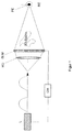
図1は、ホログラフィックダイレクトビューディスプレイの第1の可能な実施形態を、模式的に簡素化して示した図である。レーザの形態の照明手段L、変換レンズの形態の光再構成システムRO、及び画素で構成された光変調器SLMが、光の進行方向に、順に配置されている。3Dシーンの再構成は光変調器SLMと視点位置PEとの間に延びる、円錐形状の再構成空間に描画される。3Dシーンの再構成は、この視点位置PEにおいて観察者により全体を見ることができる。ここで、視点位置PEは、変換レンズの後方焦点面に存在する。照明と、その光が通る光学的経路におけるコンポーネントは、制御手段CMによって制御される。 FIG. 1 is a diagram schematically illustrating a first possible embodiment of a holographic direct view display. An illuminating means L in the form of a laser, an optical reconstruction system RO in the form of a conversion lens, and an optical modulator SLM composed of pixels are sequentially arranged in the light traveling direction. The reconstruction of the 3D scene is drawn in a conical reconstruction space extending between the light modulator SLM and the viewpoint position PE. The reconstruction of the 3D scene can be viewed entirely by the observer at this viewpoint position PE. Here, the viewpoint position PE exists on the rear focal plane of the conversion lens. The illumination and the components in the optical path through which the light passes are controlled by the control means CM.
光変調器LSMとその手前にある変換レンズは、制御手段CMによって外部的に制御されるレーザによって、十分にコヒーレントな光で照明される。光の進行する方向は、矢印で示されている。レーザを高速にオン、オフすることにより、制御手段CMは、ハイペースな、コヒーレントな光パルス列を生成する。ここで、各パルスは複素波面を表し、各光パルスは異なる波長を有する。光パルスは、図1において、矢印線上の多重強度のカーブにより示されている。
個々の、わずかに異なる光パルスの波長は、制御手段CMにおけるそれぞれにプログラムされた命令により、或いは与えられた制限内のランダムな揺らぎ(fluctuation)にさらされることにより、定義された方法で変更することができる。波長の変更は、後続の再構成とそれぞれのスペックルパターンが平均化されるときに大きな違いをもたないように、数ナノメータの範囲で実現されることが好ましい。
高速ペースの光パルスの列は、光変調器SLMにおいて3Dシーンのエンコードされたホログラム値で変調され、光変調器SLMの手前に配置された変換レンズの後方焦点面BEに、高速ペースで、次々と変換されていく。変換レンズは、また、光再構成システムROを表している。光再構成システムROの後方焦点面BEは、視点位置PEが常時位置する再構成空間に存在する。
変調された、複素波面は、再構成空間において同じ場所でわずかに異なるスペックルパターンとともに、高速ペースで、次々と同じ3Dシーンの複数の再構成を生成する。再構成は、視点位置PEから観察者の目により、平均化されたスペックルパターンをもつ単一の3Dシーンの再構成として知覚される。
高速ペースの光パルス列が生成されるが、同じホログラムが一般的なリフレッシュ頻度をもつ光変調器上で表示可能であることが好ましい。したがって、ホログラム計算は、このリフレッシュ頻度で実現できれば良い。
The light modulator LSM and the conversion lens in front of it are illuminated with sufficiently coherent light by a laser externally controlled by the control means CM. The direction of light travel is indicated by an arrow. By turning on and off the laser at high speed, the control means CM generates a high-paced, coherent optical pulse train. Here, each pulse represents a complex wavefront, and each optical pulse has a different wavelength. The light pulse is shown in FIG. 1 by a multi-intensity curve on the arrow line.
The wavelength of an individual, slightly different light pulse is changed in a defined way by each programmed command in the control means CM or by being exposed to random fluctuations within the given limits. be able to. The wavelength change is preferably realized in the range of a few nanometers so that there is no significant difference when the subsequent reconstruction and the respective speckle pattern are averaged.
The train of fast paced light pulses is modulated with the encoded hologram values of the 3D scene in the light modulator SLM, and in turn at a fast pace, on the back focal plane BE of the conversion lens placed in front of the light modulator SLM. And will be converted. The conversion lens also represents the light reconstruction system RO. The rear focal plane BE of the optical reconstruction system RO exists in a reconstruction space where the viewpoint position PE is always located.
The modulated complex wavefront generates multiple reconstructions of the same 3D scene one after another at a fast pace with slightly different speckle patterns at the same location in the reconstruction space. The reconstruction is perceived as a reconstruction of a single 3D scene with an averaged speckle pattern by the observer's eyes from the viewpoint position PE.
Although a fast paced optical pulse train is generated, it is preferred that the same hologram can be displayed on a light modulator with a typical refresh frequency. Therefore, the hologram calculation only needs to be realized at this refresh frequency.
図1による実施形態は、別の大きな利点を有する。すなわち、いかなる付加的なコンポーネントを必要とすることなく、スペックルパターンの発生を減らすために3Dシーンの再構成の数を自由に増やすことができることである。 The embodiment according to FIG. 1 has another great advantage. That is, the number of 3D scene reconstructions can be freely increased to reduce the occurrence of speckle patterns without requiring any additional components.
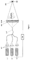
図2は、ホログラフィックダイレクトビューディスプレイの第2の可能な実施形態を模式的にかつ簡素化して示す図である。並列に配置された3つのレーザの形態としての照明手段L1,L2,L3と、隣接して配置された3つの一次元の光学的投影システムAOとしての投影手段AM、変換レンズの形態としての光学的再構成システムROと、画素化された光変調器SLMとが、光の進行方向に従って順に配置されている。本実施形態では、目によって平均化されるべく、3つのわずかに異なるスペックルパターンを有する3つのわずかに異なる再構成を生成可能となっている。より多くの再構成を生成し、平均化によるスペックルの減少をより改善するために、レーザの数とそれぞれの光学的投影システムの数は自由に増加させても良いことはいうまでもない。 FIG. 2 is a schematic and simplified illustration of a second possible embodiment of a holographic direct view display. Illumination means L1, L2, L3 in the form of three lasers arranged in parallel, projection means AM as three one-dimensional optical projection systems AO arranged adjacently, and optics in the form of a conversion lens An optical reconstruction system RO and a pixelated light modulator SLM are sequentially arranged according to the traveling direction of light. In this embodiment, three slightly different reconstructions with three slightly different speckle patterns can be generated to be averaged by the eyes. It goes without saying that the number of lasers and the number of respective optical projection systems may be increased freely in order to generate more reconstructions and to improve the speckle reduction due to averaging.
3Dシーンの再構成は、光変調器SLMと視点位置PEとの間に延びる円錐形状の再構成空間において表現される。3Dシーンの再構成は、変換レンズの後方焦点面に位置する視点位置PEにおける観察者の目から全体が可視となる。照明と、その光が通過する光経路にあるコンポーネントは、制御手段CMによって制御される。 The reconstruction of the 3D scene is expressed in a conical reconstruction space extending between the light modulator SLM and the viewpoint position PE. The reconstruction of the 3D scene is entirely visible from the observer's eyes at the viewpoint position PE located on the rear focal plane of the conversion lens. The illumination and the components in the light path through which the light passes are controlled by the control means CM.
制御手段CMにおけるプログラムによって開始され、わずかに異なる波長を持つ3つのレーザは十分にコヒーレントな光を放出する。放出された光は、例えば、対応する光学投影システムにより光ファイバへと投影される。レーザと光学投影システムAOの両方は、一つの次元内に隣接して配置される。或いは、レーザが多数ある場合には、コンポジットコンポーネントとしてそれらを2次元に配置することも可能である。二次元のコンポジットコンポーネントの二次元投影のために適切な投影手段は、好ましくは、マトリクスレンズアレイとして形成される。
光ファイバの光は、単一の光ファイバLLFにおいて統合され、制御手段CMにおけるプログラムによって制御されて、3つのわずかに異なる波長を持つ光による合成光を変換レンズと光変調器SLMに照射する。変換レンズは異なる波長を持つ光を、その後方焦点面BE、すなわち、視点位置PEに変換する。観察者の目がこの位置におかれると、変換レンズの支援で、同時に3つの3Dシーンの再構成を生成するように、異なる波長を持つ3つの複素波面が同時に提供される。わずかに異なるスペックルパターンを持つ3つの再構成が同時に生成され、再構成空間の同じ位置にオーバーラップされるので、目はこれら再構成を平均化し、減少されたスペックルパターンをもつ単一の3Dシーンの再構成を知覚することになる。
Started by a program in the control means CM, three lasers with slightly different wavelengths emit sufficiently coherent light. The emitted light is projected onto an optical fiber by a corresponding optical projection system, for example. Both the laser and the optical projection system AO are placed adjacent in one dimension. Alternatively, if there are a large number of lasers, they can be arranged two-dimensionally as composite components. Projection means suitable for two-dimensional projection of a two-dimensional composite component are preferably formed as a matrix lens array.
The light of the optical fiber is integrated in a single optical fiber LLF and controlled by a program in the control means CM to irradiate the conversion lens and the light modulator SLM with combined light of light having three slightly different wavelengths. The conversion lens converts light having different wavelengths into its rear focal plane BE, that is, the viewpoint position PE. When the observer's eyes are in this position, three complex wavefronts with different wavelengths are provided simultaneously, with the aid of a conversion lens, to simultaneously generate three 3D scene reconstructions. Since three reconstructions with slightly different speckle patterns are generated simultaneously and overlapped at the same location in the reconstruction space, the eye averages these reconstructions and a single with a reduced speckle pattern You will perceive the reconstruction of the 3D scene.
図2に従った方法に対して、一般的なリフレッシュ頻度を有する光変調器が使用可能である。ホログラム計算は、この周波数で実現されればよい。 For the method according to FIG. 2, an optical modulator with a general refresh frequency can be used. The hologram calculation may be realized at this frequency.
好ましくは、フーリエ変換が本発明の方法において使用される。なぜなら、プログラムにより実施が容易であり、光学システムにおいて非常に精度良く実現できるからである。 Preferably, a Fourier transform is used in the method of the present invention. This is because it can be easily implemented by a program and can be realized in an optical system with very high accuracy.
ホログラムは、3Dシーンの再構成が、スクリーンの前方及び/又は後方において可視となるように、図1と図2において変化させてエンコードされても良い。ここで、光変調器SLMは、同時にスクリーンの機能を満たす。 The hologram may be encoded with variations in FIGS. 1 and 2 such that the reconstruction of the 3D scene is visible in front and / or behind the screen. Here, the light modulator SLM simultaneously fulfills the function of the screen.
図1、図2において、観察者の目の位置情報は、位置検出システム(不図示)により検出され、制御手段CMによって処理される。ここでは詳細な説明は省略する。 1 and 2, the position information of the observer's eyes is detected by a position detection system (not shown) and processed by the control means CM. Detailed description is omitted here.
以上実施形態で説明したように、本発明に従ったホログラフィックダイレクトビューディスプレイにおける3Dシーンの再構成におけるスペックルの低減のための方法は、ホログラフィック投影ディスプレイに適用することができる。 As described above, the method for speckle reduction in 3D scene reconstruction in a holographic direct view display according to the present invention can be applied to a holographic projection display.
Claims (12)
3Dシーンのホログラムがエンコードされた、コントローラブルな光変調器が、十分にコヒーレントな光で照明され、
空間的に変調された光が、再構成空間を通して光再構成システムによって目の位置へ変換され、ここで前記目の位置は前記光再構成システムの後方焦点面に位置しており、前記光再構成システムは再構成空間において3Dシーンを再構成し、
前記照明は制御手段によって制御され、
前記制御手段(CM)は、異なる波長をもつ複数の複素波面が前記光変調器を通過してエンコードされたホログラム値で変調され、変調された複素波面は前記光再構成システム(RO)によって前記目の位置(PE)に変換され、前記再構成空間の同じ位置にわずかに異なるスペックルパターンをもつ3Dシーンの複数の再構成を生成し、前記複数の再構成が前記目の位置(PE)から平均化されてスペックルが減少された単一の前記3Dシーンの再構成(RE)となるように、前記コヒーレント光の少なくとも一つの特性に作用することを特徴とするスペックルを減少する方法。 A method for reducing speckle in a three-dimensional holographic reconstruction generated in a holographic display device comprising:
A controllable light modulator, encoded with a hologram of a 3D scene, is illuminated with sufficiently coherent light,
The spatially modulated light is converted into an eye position by an optical reconstruction system through the reconstruction space, where the eye position is located in the back focal plane of the optical reconstruction system and The composition system reconstructs the 3D scene in the reconstruction space,
The illumination is controlled by control means;
The control means (CM) modulates a plurality of complex wavefronts having different wavelengths with a hologram value encoded through the optical modulator, and the modulated complex wavefront is modulated by the optical reconstruction system (RO). Converted to an eye position (PE) to generate multiple reconstructions of a 3D scene with slightly different speckle patterns at the same position in the reconstruction space, the multiple reconstructions being the eye position (PE) A method for reducing speckle, characterized by acting on at least one characteristic of the coherent light so as to be a reconstruction (RE) of a single said 3D scene averaged to reduce speckle .
前記高速ペースの光のパルス列は前記光変調器(SLM)を通過し、そこで、前記光のパルスの複素波面が前記エンコードされたホログラム値で変調され、
変調された複素波面の高速ペースの列が前記再構成空間の前記目の位置(PE)に変換され、同じ3Dシーンの複数の再構成が、前記再構成空間の同じ位置に高速ペースで次々と生成される、請求項1に記載のスペックルを減少する方法。 The illumination means (L) is controlled by the control means (CM) and is fast paced coherent with slightly different wavelengths to illuminate the optical reconstruction system (RO) and the light modulator (SLM). A pulse train of light,
The fast-paced pulse train of light passes through the light modulator (SLM), where the complex wavefront of the light pulse is modulated with the encoded hologram value;
A fast paced sequence of modulated complex wavefronts is converted to the eye position (PE) in the reconstruction space, and multiple reconstructions of the same 3D scene are successively placed at the same location in the reconstruction space at a fast pace. The method of reducing speckles according to claim 1, wherein the speckles are generated.
わずかに異なる波長をもつ前記複素波面は同時に前記光変調器(SLM)を通過し、ここで、それらは前記エンコードされたホログラム値で変調され、
複数の変調された複素波面は同時に、前記再構成空間における前記目の位置(PE)へ変換され、前記再構成空間における同じ位置に前記同じ3Dシーンの複数の再構成を同時に生成し、オーバーラップさせる、請求項1に記載のスペックルを減少する方法。 A plurality of illumination means acted by said control means (CM) such that a complex wavefront with several slightly different wavelengths simultaneously illuminates the optical reconstruction system (RO) and the light modulator (SLM) (L1,... Ln) simultaneously emits coherent light,
The complex wavefronts with slightly different wavelengths pass through the light modulator (SLM) at the same time, where they are modulated with the encoded hologram values,
Multiple modulated complex wavefronts are simultaneously converted to the eye position (PE) in the reconstruction space to simultaneously generate multiple reconstructions of the same 3D scene at the same position in the reconstruction space. The method of reducing speckles according to claim 1.
光再構成システム(RO)と光変調器(SLM)とを照明するために、わずかに異なる波長をもつコヒーレント光の高速ペースのパルス列を放出する照明手段(L)と、
変調された複素波面の高速ペースの列を再構成空間における目の位置(PE)に変換し、光再構成空間に同じ3Dシーンの複数の再構成を高速ペースで次から次へと生成する光再構成システム(RO)と、
3Dシーンのホログラムがエンコードされている、光変調器(SLM)の形態のエンコーディング手段と、
前記照明手段(L)と、前記エンコーディング手段と、前記光再構成システム(RO)とを制御する制御手段(CM)と、
が光の進行方向に提供されていることを特徴とするホログラフィックディスプレイデバイス。 A holographic display device for performing the method of claim 2, comprising:
Illumination means (L) for emitting a fast paced pulse train of coherent light having slightly different wavelengths to illuminate the optical reconstruction system (RO) and the light modulator (SLM);
Light that transforms a fast-paced sequence of modulated complex wavefronts into eye positions (PE) in reconstruction space and generates multiple reconstructions of the same 3D scene in light reconstruction space from one to the next at a fast pace A reconfiguration system (RO);
Encoding means in the form of a light modulator (SLM) in which a hologram of a 3D scene is encoded;
Control means (CM) for controlling the illumination means (L), the encoding means, and the optical reconstruction system (RO);
Is provided in the direction of light travel, a holographic display device.
わずかに異なる波長のコヒーレント光を同時に放出し、光再構成システム(RO)と光変調器(SLM)とを同時に照明する複数の照明手段(L1、…Ln)と、
複数の変調された複素波面を再構成空間の目の位置(PE)に同時に変換し、再構成空間の同じ位置に前記同じ3Dシーンの複数の再構成を同時に生成しオーバーラップさせる光再構成手段(RO)と、
3Dシーンのホログラムがエンコードされた、光変調器(SLM)の形態のエンコーディング手段と、
少なくとも一つの次元に隣接して配置された複数の光投影系を備え、前記照明手段(L1,…Ln)の前記コヒーレント光を複数の光ファイバへ投影する投影手段(AM)と、
前記照明手段(L1,…Ln)と前記エンコーディング手段と前記光再構成システム(RO)とを制御する制御手段(CM)と、
が光の進行方向に提供されていることを特徴とするホログラフィックディスプレイデバイス。 A holographic display device for performing the method of claim 3, comprising:
A plurality of illumination means (L1,... Ln) that simultaneously emit coherent light of slightly different wavelengths and illuminate the optical reconstruction system (RO) and the light modulator (SLM) simultaneously;
Optical reconstruction means for simultaneously transforming a plurality of modulated complex wavefronts to the eye position (PE) of the reconstruction space and simultaneously generating and overlapping a plurality of reconstructions of the same 3D scene at the same position of the reconstruction space (RO),
Encoding means in the form of a light modulator (SLM) in which a hologram of a 3D scene is encoded;
A plurality of light projection systems arranged adjacent to each other in at least one dimension, and projecting means (AM) for projecting the coherent light of the illumination means (L1,... Ln) onto a plurality of optical fibers;
Control means (CM) for controlling the illumination means (L1,... Ln), the encoding means, and the optical reconstruction system (RO);
Is provided in the direction of light travel, a holographic display device.
Applications Claiming Priority (3)
| Application Number | Priority Date | Filing Date | Title |
|---|---|---|---|
| DE102006062376.2A DE102006062376B4 (en) | 2006-12-19 | 2006-12-19 | Method and display device for reducing speckle |
| DE102006062376.2 | 2006-12-19 | ||
| PCT/EP2007/063246 WO2008074628A1 (en) | 2006-12-19 | 2007-12-04 | Method and device for reducing speckle |
Publications (2)
| Publication Number | Publication Date |
|---|---|
| JP2010513962A true JP2010513962A (en) | 2010-04-30 |
| JP2010513962A5 JP2010513962A5 (en) | 2012-10-25 |
Family
ID=39047042
Family Applications (1)
| Application Number | Title | Priority Date | Filing Date |
|---|---|---|---|
| JP2009541955A Pending JP2010513962A (en) | 2006-12-19 | 2007-12-04 | Method and apparatus for reducing speckle |
Country Status (5)
| Country | Link |
|---|---|
| US (1) | US8355190B2 (en) |
| JP (1) | JP2010513962A (en) |
| DE (1) | DE102006062376B4 (en) |
| TW (1) | TWI396951B (en) |
| WO (1) | WO2008074628A1 (en) |
Cited By (2)
| Publication number | Priority date | Publication date | Assignee | Title |
|---|---|---|---|---|
| WO2012147271A1 (en) * | 2011-04-27 | 2012-11-01 | パナソニック株式会社 | Display device |
| JP2013536451A (en) * | 2010-07-06 | 2013-09-19 | シーリアル テクノロジーズ ソシエテ アノニム | Holographic display |
Families Citing this family (13)
| Publication number | Priority date | Publication date | Assignee | Title |
|---|---|---|---|---|
| DE102007036127A1 (en) * | 2007-07-27 | 2009-01-29 | Seereal Technologies S.A. | Holographic reconstruction device |
| JP5451238B2 (en) * | 2009-08-03 | 2014-03-26 | 浜松ホトニクス株式会社 | Laser processing method |
| EP3404452B1 (en) * | 2010-09-07 | 2020-10-28 | Dai Nippon Printing Co., Ltd. | Projection type image display apparatus and corresponding method |
| GB201201936D0 (en) * | 2012-02-03 | 2012-03-21 | Univ Southampton | Super-oscillatory lens device |
| US9709953B2 (en) | 2012-08-01 | 2017-07-18 | Real View Imaging Ltd. | Despeckling a computer generated hologram |
| JP6150253B2 (en) * | 2013-09-26 | 2017-06-21 | アルプス電気株式会社 | Video display device |
| US9599572B2 (en) | 2014-04-07 | 2017-03-21 | Orbotech Ltd. | Optical inspection system and method |
| CN106873341B (en) * | 2017-04-19 | 2022-11-04 | 京东方科技集团股份有限公司 | Holographic display device, driving method thereof and display cabinet |
| CN111032687A (en) | 2017-05-25 | 2020-04-17 | 普瑞利思生物制品公司 | Three-dimensional printed organs, devices and substrates |
| WO2020028431A1 (en) * | 2018-07-31 | 2020-02-06 | Prellis Biologics, Inc. | Methods and systems for three-dimensional printing |
| KR20200101044A (en) * | 2019-02-19 | 2020-08-27 | 삼성전자주식회사 | Multi-image display apparatus providing holographic image |
| DE102019110587A1 (en) * | 2019-04-24 | 2020-10-29 | HELLA GmbH & Co. KGaA | Device for producing a replica hologram, replica hologram and lighting device for a vehicle |
| CN111176094B (en) * | 2020-01-14 | 2022-02-01 | 四川长虹电器股份有限公司 | Laser holographic projection display method and device |
Citations (4)
| Publication number | Priority date | Publication date | Assignee | Title |
|---|---|---|---|---|
| JPH09508476A (en) * | 1994-01-31 | 1997-08-26 | エス・ディー・エル・インコーポレイテッド | Laser lighting display system |
| JP2001510587A (en) * | 1997-02-07 | 2001-07-31 | ダイムラークライスラー・アクチェンゲゼルシャフト | Holographic screen with integrated speckle reduction |
| JP2006506660A (en) * | 2002-11-13 | 2006-02-23 | シーリアル、テクノロジーズ、ゲーエムベーハー | Image hologram and image hologram reproducing apparatus |
| JP2008541145A (en) * | 2005-05-06 | 2008-11-20 | シーリアル、テクノロジーズ、ゲーエムベーハー | Device for holographic reconstruction of 3D scenes |
Family Cites Families (6)
| Publication number | Priority date | Publication date | Assignee | Title |
|---|---|---|---|---|
| JP3238755B2 (en) * | 1992-08-21 | 2001-12-17 | 富士通株式会社 | Hologram creation and stereoscopic display method and stereoscopic display device |
| DE19541071A1 (en) | 1995-11-03 | 1997-05-07 | Bundesdruckerei Gmbh | Process for the production of counterfeit-proof holograms with authenticity features and reader for checking the authenticity |
| DE10137832B4 (en) | 2001-04-12 | 2006-09-14 | Tesa Scribos Gmbh | Method and device for reading out a hologram stored in a storage medium |
| TW472225B (en) * | 2001-06-08 | 2002-01-11 | Shiu-Hua Huang | Sequential type projection apparatus |
| WO2005045531A1 (en) * | 2003-10-27 | 2005-05-19 | Bauhaus-Universität Weimar | Method and arrangement for combining holograms with computer graphics |
| DE102004063838A1 (en) * | 2004-12-23 | 2006-07-06 | Seereal Technologies Gmbh | Method and apparatus for calculating computer generated video holograms |
-
2006
- 2006-12-19 DE DE102006062376.2A patent/DE102006062376B4/en active Active
-
2007
- 2007-12-04 WO PCT/EP2007/063246 patent/WO2008074628A1/en active Application Filing
- 2007-12-04 JP JP2009541955A patent/JP2010513962A/en active Pending
- 2007-12-04 US US12/520,156 patent/US8355190B2/en active Active
- 2007-12-12 TW TW096147570A patent/TWI396951B/en active
Patent Citations (4)
| Publication number | Priority date | Publication date | Assignee | Title |
|---|---|---|---|---|
| JPH09508476A (en) * | 1994-01-31 | 1997-08-26 | エス・ディー・エル・インコーポレイテッド | Laser lighting display system |
| JP2001510587A (en) * | 1997-02-07 | 2001-07-31 | ダイムラークライスラー・アクチェンゲゼルシャフト | Holographic screen with integrated speckle reduction |
| JP2006506660A (en) * | 2002-11-13 | 2006-02-23 | シーリアル、テクノロジーズ、ゲーエムベーハー | Image hologram and image hologram reproducing apparatus |
| JP2008541145A (en) * | 2005-05-06 | 2008-11-20 | シーリアル、テクノロジーズ、ゲーエムベーハー | Device for holographic reconstruction of 3D scenes |
Cited By (4)
| Publication number | Priority date | Publication date | Assignee | Title |
|---|---|---|---|---|
| JP2013536451A (en) * | 2010-07-06 | 2013-09-19 | シーリアル テクノロジーズ ソシエテ アノニム | Holographic display |
| WO2012147271A1 (en) * | 2011-04-27 | 2012-11-01 | パナソニック株式会社 | Display device |
| US9134700B2 (en) | 2011-04-27 | 2015-09-15 | Panasonic Intellectual Property Management Co., Ltd. | Display device |
| JP5927559B2 (en) * | 2011-04-27 | 2016-06-01 | パナソニックIpマネジメント株式会社 | Display device |
Also Published As
| Publication number | Publication date |
|---|---|
| US8355190B2 (en) | 2013-01-15 |
| TW200846855A (en) | 2008-12-01 |
| TWI396951B (en) | 2013-05-21 |
| DE102006062376B4 (en) | 2018-03-22 |
| US20090296176A1 (en) | 2009-12-03 |
| WO2008074628A1 (en) | 2008-06-26 |
| DE102006062376A1 (en) | 2008-06-26 |
Similar Documents
| Publication | Publication Date | Title |
|---|---|---|
| JP2010513962A (en) | Method and apparatus for reducing speckle | |
| JP5541924B2 (en) | Method and apparatus for reducing speckle | |
| JP5180064B2 (en) | Device for holographic reconstruction of 3D scenes | |
| KR102136143B1 (en) | Holographic projector | |
| JP4988705B2 (en) | Controllable lighting device | |
| JP4695141B2 (en) | Method and apparatus for encoding and reconstructing a computer generated video hologram | |
| CN108055867A (en) | Display system | |
| CA2637751A1 (en) | Projection device for the holographic reconstruction of scenes | |
| CA2375460A1 (en) | Holographic displays | |
| KR20100057832A (en) | Holographic display having improved reconstruction quality | |
| US8441703B2 (en) | Method and device for holographically reconstructing a scene | |
| US9013773B2 (en) | Back light unit providing direction controllable collimated light beam and 3D display using the same | |
| US11567451B2 (en) | Holographic display apparatus and method for providing expanded viewing window | |
| JP2017062373A (en) | Image reproducing apparatus | |
| Rong et al. | A hogel-based holographic recording system and its hologram reconstruction improvement | |
| Kang et al. | Color holographic wave-front printing technique | |
| Utsugi et al. | A new approach for speckle reduction in holographic 3D printer |
Legal Events
| Date | Code | Title | Description |
|---|---|---|---|
| A621 | Written request for application examination |
Free format text: JAPANESE INTERMEDIATE CODE: A621 Effective date: 20101125 |
|
| A521 | Request for written amendment filed |
Free format text: JAPANESE INTERMEDIATE CODE: A523 Effective date: 20120904 |
|
| A977 | Report on retrieval |
Free format text: JAPANESE INTERMEDIATE CODE: A971007 Effective date: 20121220 |
|
| A131 | Notification of reasons for refusal |
Free format text: JAPANESE INTERMEDIATE CODE: A131 Effective date: 20130204 |
|
| A601 | Written request for extension of time |
Free format text: JAPANESE INTERMEDIATE CODE: A601 Effective date: 20130502 |
|
| A602 | Written permission of extension of time |
Free format text: JAPANESE INTERMEDIATE CODE: A602 Effective date: 20130513 |
|
| A02 | Decision of refusal |
Free format text: JAPANESE INTERMEDIATE CODE: A02 Effective date: 20131007 |