JP2010512807A - Coated cannula with protective tip for insertion into a patient - Google Patents
Coated cannula with protective tip for insertion into a patient Download PDFInfo
- Publication number
- JP2010512807A JP2010512807A JP2009540466A JP2009540466A JP2010512807A JP 2010512807 A JP2010512807 A JP 2010512807A JP 2009540466 A JP2009540466 A JP 2009540466A JP 2009540466 A JP2009540466 A JP 2009540466A JP 2010512807 A JP2010512807 A JP 2010512807A
- Authority
- JP
- Japan
- Prior art keywords
- section
- cannula
- shoulder
- outer diameter
- coating
- Prior art date
- Legal status (The legal status is an assumption and is not a legal conclusion. Google has not performed a legal analysis and makes no representation as to the accuracy of the status listed.)
- Pending
Links
Images


Classifications
-
- A—HUMAN NECESSITIES
- A61—MEDICAL OR VETERINARY SCIENCE; HYGIENE
- A61M—DEVICES FOR INTRODUCING MEDIA INTO, OR ONTO, THE BODY; DEVICES FOR TRANSDUCING BODY MEDIA OR FOR TAKING MEDIA FROM THE BODY; DEVICES FOR PRODUCING OR ENDING SLEEP OR STUPOR
- A61M25/00—Catheters; Hollow probes
-
- A—HUMAN NECESSITIES
- A61—MEDICAL OR VETERINARY SCIENCE; HYGIENE
- A61M—DEVICES FOR INTRODUCING MEDIA INTO, OR ONTO, THE BODY; DEVICES FOR TRANSDUCING BODY MEDIA OR FOR TAKING MEDIA FROM THE BODY; DEVICES FOR PRODUCING OR ENDING SLEEP OR STUPOR
- A61M25/00—Catheters; Hollow probes
- A61M25/01—Introducing, guiding, advancing, emplacing or holding catheters
- A61M25/06—Body-piercing guide needles or the like
- A61M25/065—Guide needles
-
- A—HUMAN NECESSITIES
- A61—MEDICAL OR VETERINARY SCIENCE; HYGIENE
- A61M—DEVICES FOR INTRODUCING MEDIA INTO, OR ONTO, THE BODY; DEVICES FOR TRANSDUCING BODY MEDIA OR FOR TAKING MEDIA FROM THE BODY; DEVICES FOR PRODUCING OR ENDING SLEEP OR STUPOR
- A61M25/00—Catheters; Hollow probes
- A61M25/01—Introducing, guiding, advancing, emplacing or holding catheters
- A61M25/06—Body-piercing guide needles or the like
- A61M25/0662—Guide tubes
-
- A—HUMAN NECESSITIES
- A61—MEDICAL OR VETERINARY SCIENCE; HYGIENE
- A61M—DEVICES FOR INTRODUCING MEDIA INTO, OR ONTO, THE BODY; DEVICES FOR TRANSDUCING BODY MEDIA OR FOR TAKING MEDIA FROM THE BODY; DEVICES FOR PRODUCING OR ENDING SLEEP OR STUPOR
- A61M37/00—Other apparatus for introducing media into the body; Percutany, i.e. introducing medicines into the body by diffusion through the skin
-
- A—HUMAN NECESSITIES
- A61—MEDICAL OR VETERINARY SCIENCE; HYGIENE
- A61M—DEVICES FOR INTRODUCING MEDIA INTO, OR ONTO, THE BODY; DEVICES FOR TRANSDUCING BODY MEDIA OR FOR TAKING MEDIA FROM THE BODY; DEVICES FOR PRODUCING OR ENDING SLEEP OR STUPOR
- A61M25/00—Catheters; Hollow probes
- A61M25/01—Introducing, guiding, advancing, emplacing or holding catheters
- A61M25/06—Body-piercing guide needles or the like
- A61M25/065—Guide needles
- A61M2025/0656—Guide needles having a tip larger than the rest of the body
Landscapes
- Health & Medical Sciences (AREA)
- Life Sciences & Earth Sciences (AREA)
- Engineering & Computer Science (AREA)
- Hematology (AREA)
- General Health & Medical Sciences (AREA)
- Anesthesiology (AREA)
- Biomedical Technology (AREA)
- Heart & Thoracic Surgery (AREA)
- Veterinary Medicine (AREA)
- Animal Behavior & Ethology (AREA)
- Public Health (AREA)
- Pulmonology (AREA)
- Biophysics (AREA)
- Dermatology (AREA)
- Medical Informatics (AREA)
- Surgical Instruments (AREA)
- Prostheses (AREA)
- Media Introduction/Drainage Providing Device (AREA)
Abstract
本出願は、患者に挿入するためのカニューレに関する。カニューレは、第1の遠位側区間と第2の近位側区間を含んでおり、それぞれを貫いて中空の内部が伸張している。第1区間は第2区間より遠位側に配置され、より大きな外径を含んでいる。コーティングは第2区間に施されている。コーティングの外径は、第1区間の外径より小さいか又はこれと等しくなっている。この設計は、患者へカニューレを挿入する間に、コーティングが第2区間から剥がれ落ちるのを防止している。1つの実施形態では、カニューレは、コーティングを患者に挿入する際のガイドの役目を果たし、第1区間は、コーティングの先導縁を保護している。
【選択図】図1The present application relates to a cannula for insertion into a patient. The cannula includes a first distal section and a second proximal section with a hollow interior extending therethrough. The first section is located distal to the second section and includes a larger outer diameter. The coating is applied to the second section. The outer diameter of the coating is smaller than or equal to the outer diameter of the first section. This design prevents the coating from coming off the second section during cannulation of the patient. In one embodiment, the cannula serves as a guide as the coating is inserted into the patient, and the first section protects the leading edge of the coating.
[Selection] Figure 1
Description
本発明は、患者へ挿入されるカニューレに、より詳しくは、コーティングの付着を維持するため、保護用先端部を備えている被覆カニューレに関する。 The present invention relates to a coated cannula with a protective tip to maintain adhesion of the coating to a cannula inserted into a patient, and more particularly.
様々な医療処置では、医師が、患者の組織又は骨を検査すること、患者の組織又は骨のサンプルを採取すること、或いは骨髄腔に穿刺して骨、骨髄、又は骨髄液を取り出すことが必要になる。それらの処置では、医師が、組織、又は骨の硬い外側の層を穿刺するのに尖った器具を使用することが必要になる。それらの処置では、器具は、骨の中に挿入している間に曲がったり破損したりするのを防ぐための剛性と、骨及び周辺組織に対する不必要な損傷を防止するために最小寸法であることを含め、複数の属性を兼ね備えていることが求められる。 Various medical procedures require the physician to examine the patient's tissue or bone, take a sample of the patient's tissue or bone, or puncture the bone marrow cavity to remove bone, bone marrow, or bone marrow fluid become. These procedures require the physician to use pointed instruments to puncture the tissue or the hard outer layer of bone. In these procedures, the instrument is minimally sized to prevent bending and breakage during bone insertion and to prevent unnecessary damage to the bone and surrounding tissue during insertion. Including a plurality of attributes.
尖った器具は、外表面に付着させたコーティングを含んでいる場合がある。コーティングは、患者へ挿入し易くするための潤滑性や、器具を電気的処置と組み合わせて使用する場合の電気的絶縁性を含め、様々な理由で必要になることがある。先行技術による装置に伴う問題は、骨の中に挿入している間に器具からコーティングが剥がれるということである。これは、骨の密度が器具に対するコーティングの接着力に勝り、コーティングがむしり取られたり剥ぎ取られたりする事態を引き起こすことによって生じる。処理が、組織及び/又は骨に何度も挿入することを必要とする場合は、コーティングの破損が益々起こり易くなる。 A sharp instrument may include a coating attached to the outer surface. The coating may be necessary for a variety of reasons, including lubricity to facilitate insertion into the patient and electrical insulation when the instrument is used in conjunction with an electrical procedure. A problem with prior art devices is that the coating peels away from the instrument during insertion into the bone. This is caused by the fact that the density of the bone is superior to the adhesion of the coating to the device, causing the coating to be stripped or stripped. If the process requires repeated insertion into the tissue and / or bone, coating failure is more likely to occur.
骨挿入用の尖った器具を使用する処置の一例に、神経統合性のモニタリングがある。神経統合性モニタリングは、プローブを患者の骨の中へ穿刺する術中処置である。プローブを通して電流を流し、神経への近接度、運動神経過敏又は位置が関係した神経障害、及び脊髄運動伝導統合性の様な、外科処置データを判定する。プローブは、前もって骨に挿入されているカニューレを通して骨の中へ挿入される。カニューレは、プローブと周辺組織の間に絶縁バリアを形成する誘電性コーティングを含んでいる。精度の高い結果を得るためには、カニューレに付着させた誘電性コーティングの維持が重要である。 One example of a procedure that uses a pointed instrument for bone insertion is nerve integrity monitoring. Nerve integrity monitoring is an intraoperative procedure in which a probe is punctured into a patient's bone. Current is passed through the probe to determine surgical data such as proximity to nerves, motor hypersensitivity or location related neurological disorders, and spinal motor conduction integration. The probe is inserted into the bone through a cannula that has been previously inserted into the bone. The cannula includes a dielectric coating that forms an insulating barrier between the probe and surrounding tissue. In order to obtain accurate results, it is important to maintain a dielectric coating adhered to the cannula.
本出願は、患者に挿入するためのカニューレに関する。カニューレは、第1区間と第2区間を含んでおり、それぞれを貫いて中空の内部が伸張している。第1区間は第2区間より遠位側に配置され、より大きな外径を含んでいる。コーティングは第2区間に施されることができる。コーティングの外径は、第1区間の外径より小さいか又はこれと等しくてもよい。この設計では、第1区間が、患者へカニューレを挿入する間にコーティングが第2区間から剥がれ落ちるのを防止するようになっている。1つの実施形態では、カニューレは、コーティングを患者に挿入する際のガイドの役目を果たし、第1区間は、コーティングの先導縁を保護している。 The present application relates to a cannula for insertion into a patient. The cannula includes a first section and a second section through which a hollow interior extends. The first section is located distal to the second section and includes a larger outer diameter. The coating can be applied to the second section. The outer diameter of the coating may be smaller than or equal to the outer diameter of the first section. In this design, the first section prevents the coating from peeling off from the second section during insertion of the cannula into the patient. In one embodiment, the cannula serves as a guide as the coating is inserted into the patient, and the first section protects the leading edge of the coating.
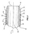
本出願は、患者に挿入するための被覆カニューレに関する。図1及び図2は、第1区間10と近位側の第2区間40の間に肩部20が形成された本体9を含んでいる、1つの実施形態のカニューレ8を示している。コーティング30は第2区間40に施されている。第1区間10の外径はコーティング30の外径よりも大きいか又はこれと等しくなっている。従って、患者へカニューレ8を挿入する間、第1区間10は、保護材として働き、コーティング30を保護して第2区間40から剥がれ落ちるのを防止する。
The present application relates to a coated cannula for insertion into a patient. 1 and 2 show one embodiment of a
本体9は、患者へ挿入している間に曲がったり破損したりしないように剛性のある材料で構成されている。図1及び図2に示している様に、本体9は、遠位端11と近位端41の間を伸張している。本体9は、第1区間10と、肩部20と、第2区間40を含んでいる。本体9は、遠位端11から近位端41までの長さに沿って伸張している中空の内部50を含んでいる。中空の内部50の幅は、本体9の長さに沿って一定であってもよいし変化していてもよい。本体9は、限定するわけではないが、ステンレス鋼、チタン、及びアルミニウムを含め、様々な材料で構成することができる。本体9は、単一要素として構成してもよいし、2つ又はそれ以上の別々の要素を一体に取り付けて構成してもよい。
The body 9 is constructed of a rigid material so that it does not bend or break during insertion into the patient. As shown in FIGS. 1 and 2, the body 9 extends between the
1つの実施形態では、第1部分10と第2部分40のそれぞれは、実質的に円形の断面形状を含んでいる。区間10、40は、楕円形又は多角形の様な他の断面形状を含んでいてもよい。また、第1区間10は、第2区間40とは異なる断面形状を含んでいてもよい。
In one embodiment, each of the
第1区間10は、患者への挿入を容易にするテーパー区間19を含んでいてもよい。テーパー区間19は、縮小した外径を有する第1長手方向位置12と、拡大した外径を有する第2長手方向位置13の間を伸張している。第1長手方向位置12は、図1と図2に示している様に本体9の遠位端11と一致していてもよいし、図3に示している様に遠位端11から近位方向内向きに間隔を空けて設けられていてもよい。
The
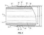
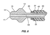
1つの実施形態では、図4に示している様に、第1区間10は、全長がテーパー形状になっている。テーパー形状は、遠位端11の第1長手方向位置12から肩部20の第2長手方向位置13まで伸張している。第1区間10は、更に、1つ又はそれ以上の非テーパー区間15を含んでいてもよい。図3は、遠位端11と第1長手方向位置12の間が第1の非テーパー区間15aになっている或る実施形態を示している。第2長手方向位置13と肩部20の間には、第2の非テーパー区間15bが配置されている。図6は、2つのテーパー区間の間に配置されている非テーパー区間15を示している。非テーパー区間15の長さは、具体的な実施形態に依って変えてもよい。
In one embodiment, as shown in FIG. 4, the
第2区間40は、第1区間10から近位方向に伸張している。図3及び図4に示しているように、第2区間40の外径Xは、第1区間10の近位側区間の外径Yよりも小さくなっている。両外径XとYの差は、図3及び図4に示すように比較的大きくてもよいし、図2に示すように比較的小さくてもよい。「径」という用語は、ここでは、断面形状の中心を通る直線で測った要素の寸法を指すのに使用されている。「径」という用語は、円形だけでなく、他の断面形状も含めて使用されている。
The
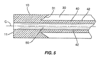
肩部20は、第1区間10と第2区間40の間の接合部に形成されている。肩部20は、第1区間10の外表面と第2区間40の外表面の間を伸張している。肩部20は、本体9の長手方向中心線Cに対して様々な角度位置に配列することができる。図2、図3、及び図4に示している1つの実施形態では、肩部20は、中心線Cに実質的に垂直に配列されている。図5は、肩部20が垂直以外の角度に配列されている或る実施形態を示している。
The
コーティング30は、第2区間40の外表面42に接着されている。カニューレ8には、様々な理由からコーティング30が必要になる場合がある。1つの実施形態では、コーティング30は、内部50の中に置かれた監視用器具と周辺組織及び/又は骨の間での短絡を防止するバリアの役目を果たす誘電性絶縁物である。コーティング30は、切断、焼灼、刺激を与えることを含め、電気外科的用途で他の機能に使用されることもある。コーティング30は、また、カニューレ8の挿入と取り出しを容易にするために、潤滑性又は耐摩擦性を提供することもできる。コーティング30は、更に、限定するわけではないが、耐腐食性、耐熱性、患者の感受性に対する保護性、耐摩擦性、抗菌保護性、対移行性、耐摩耗性、抗反射性、屈曲低減性、本体9を保護しカニューレ8の寿命を延ばす手段として、そしてカラーコード識別標示として、を含め、他にも多くの機能を提供する。
The
コーティング30の厚さは、図3及び図4に示している様に、コーティング30の外径Zが第1区間10の外径Yより小さいか又はこれと等しくなるように制限されている。この寸法に設定することによって、カニューレ8を患者へ挿入する際にコーティング30が保護される。第1区間10は、組織及び/又は骨に、カニューレ8の近位側区画を挿入するための開口部を形成するシールド(shield)の役目を果たす。1つの特定の実施形態では、本体9は、コーティング30を患者へ挿入する際のガイドの役目を果たす。第2区間40は、コーティング30用のホルダになっている。第1区間10は、コーティング30の先導縁31が第2区間40から分離するのを防止している。
The thickness of the
第2区間40には多種多様なコーティング30を施すことができる。コーティング30の例としては、限定するわけではないが、テフロン(TEFLON)、リルサン(RISLAN)を含むナイロン、ポリエーテルエーテルケトン(PEEK)、ポリテトラフルオロエチレン(PTFE)、プラスチック、キシラン、ハーラー(HALAR)、テフゼル(TEFZEL)、フッ素重合体、調整仕上げ剤、フェノール樹脂、エポキシ、ビニール、及びアクリル樹脂が挙げられる。コーティング30は、第2区間40の外部に形成された陽極酸化層又は亜鉛メッキ層であってもよい。コーティング30は、限定するわけではないが、液体散布、粉末コーティング、浸漬コーティング、収縮包装、モールド成形、表面硬化、金属被覆、電気アーク、溶射、プラズマ溶射、高速酸素燃料、及び接着剤を含め、多種多様なやり方で、第2区間40に施すことができる。
A wide variety of
1つの実施形態では、コーティング30の先導縁31(即ち、遠位縁)は、図2、図3、図4、及び図5に示すように、肩部20に接している。図6に示している別の実施形態では、先導縁31は、肩部20から間隔を空けて配置されている。1つの実施形態では、コーティング30との間隔を空けるために肩部20に隣接してスペーサ85が配置されている。
In one embodiment, the leading edge 31 (ie, the distal edge) of the
コーティング30は、第2区間40の或る限定された長さ部分又は全体に施すことができる。図1は、第2区間40の肩部20から長手方向位置38までコーティング30を施した或る実施形態を示している。第2区間の位置38から近位端41までの残りの長さ部分は、コーティングが施されていない。第2区間40は、様々な形状及び寸法を含んでいてもよい。1つの実施形態では、第2区間40は、実質的に一定の外径を含んでいる。図1に示している別の実施形態では、第2区間40は、上で説明した様に、第1区間20に隣接する縮小した外径Xを有する第1近位側長さ部分45を含んでいる。第2近位側長さ部分46は、より大きな外径を含んでいる。
The
中空の内部50は、各種器具を受け入れることのできる大きさに作られている。1つの実施形態では、内部50は、患者の骨又は組織の中へと穿刺するための先の尖った先端又は切削用刃先を含んでいるスタイレットを受け入れることのできる大きさに作られている。スタイレットには、神経統合性モニタリングシステムの一部として電気プローブの働きをさせてもよい。内部50は、幅が、本体9の長さに沿って実質的に同じであってもよいし、変化していてもよい。
The
カニューレ8を使用する状況の1つは脊椎治療時である。カニューレは、頸椎、胸椎、腰椎、及び/又は仙骨部位を含め脊椎の様々な部位に沿った椎骨部材又は脊柱管の中へ挿入される大きさに作られている。更に、カニューレ8は、他の脊椎以外の関係に使用することもできるものと理解頂きたい。
One situation where the
「遠位」という用語は、一般的には、患者の方向に又は装置の使用者から遠くに、と定義される。反対に、「近位」という用語は、一般には、患者から遠くに又は使用者に向かって、という意味である。空間に関係する用語、例えば、「下」、「下方」、「下側」、「上」、「上側」などは、第1要素の第2要素に対する位置を説明する上で記述を分かり易くするために使用している。それらの用語は、図に描かれている向きとは異なる向きの他に、装置の様々な向きを包含するものとする。更に、「第1」、「第2」などの様な用語も、各種要素、部位、区間、その他を記述するために使用されており、同様に、限定を課す意図はない。説明全般を通して、類似の用語は類似の要素を指している。 The term “distal” is generally defined as in the direction of the patient or far from the user of the device. Conversely, the term “proximal” generally means away from the patient or toward the user. Terms related to space, such as “lower”, “lower”, “lower”, “upper”, “upper”, etc. make the description easier to understand in describing the position of the first element relative to the second element. Is used for. These terms are intended to encompass various orientations of the device in addition to orientations different from those depicted in the figures. Furthermore, terms such as “first”, “second”, etc. are used to describe various elements, sites, sections, etc., and are similarly not intended to impose limitations. Throughout the description, similar terms refer to similar elements.
ここで使用する場合、「有している」、「保有している」、「含んでいる」、「備えている」などの用語は、言及した要素又は特徴の存在を表しているが、但し追加の要素又は特徴を排除しない、制約のない用語である。英文不定冠詞及び定冠詞の対訳である「或る」、「一」、及び「当該」は、文脈上明白に他に指定の無い限り、単数形だけでなく複数形も含むものとする。 As used herein, terms such as “having”, “having”, “including”, “having” indicate the presence of the referenced element or feature, provided that An unconstrained term that does not exclude additional elements or features. The parallel translations of English indefinite articles and definite articles "a", "one", and "related" are intended to include the plural as well as the singular, unless the context clearly indicates otherwise.
本発明は、本発明の範囲及び本質的な特徴から逸脱すること無く、ここでこれまでに述べたもの以外の他の特定のやり方で実施してもよい。本実施形態は、従って、あらゆる点で、説明を目的としており、限定を課すものではないと考えられるべきであり、特許請求の範囲に記載の請求項の意味及び等価範囲に入るあらゆる変更は、それに包含されるものとする。 The present invention may be implemented in other specific ways than those hereinbefore described without departing from the scope and essential characteristics of the invention. This embodiment is, therefore, to be considered in all respects as illustrative and not restrictive, and any modifications that fall within the meaning and range of equivalency of the claims set forth in the claims are intended to be It shall be included in it.
8 カニューレ
9 本体
10 第1区間
11 遠位端
12 第1長手方向位置
13 第2長手方向位置
15、15a、15b 非テーパー区間
19 テーパー区間
20 肩部
30 コーティング
31 先導縁
40 第2区間
41 近位端
42 外表面
45 第1近位側長さ部分
46 第2近位側長さ部分
50 中空の内部
85 スペーサ
C 中心線
X、Y、Z 外径
8 Cannula 9
Claims (26)
円筒形外表面を有する遠位側区間と、
前記遠位側区間に隣接し、円筒形外表面を含んでいる第2区間であって、前記遠位側区間よりも小さい外径を含んでいる、第2区間と、
前記遠位側区間と前記第2区間の接合部に形成されている肩部と、
前記第2区間の前記円筒形外表面に付着されたコーティングであって、前記遠位側区間の外径より小さいか又はこれと等しい外径を有するコーティングと、を備えているカニューレ。 A cannula to be inserted into a patient,
A distal section having a cylindrical outer surface;
A second section adjacent to the distal section and including a cylindrical outer surface, the second section including an outer diameter smaller than the distal section;
A shoulder formed at the junction of the distal section and the second section;
A cannula comprising a coating applied to the cylindrical outer surface of the second section and having an outer diameter less than or equal to the outer diameter of the distal section.
縮小した外径を有する先端部から拡大した外径を有する肩部までの間を伸張しているテーパー形状の第1区間と、
前記第1区間に隣接し、該第1区間から近位方向外向きに伸張している第2区間であって、前記肩部の前記拡大した外径より小さい第2区間外径を有している、第2区間と、
前記第2区間の外表面に、前記肩部と接触して付着されたコーティングであって、コーティング外径は、前記肩部の前記拡大した外径より小さいか又はこれと等しい、コーティングと、
前記第1及び第2区間を通って伸張する中空の内部と、を備えているカニューレ。 A cannula to be inserted into a patient,
A tapered first section extending from a tip having a reduced outer diameter to a shoulder having an enlarged outer diameter;
A second section adjacent to the first section and extending outwardly in a proximal direction from the first section, the second section having a second section outer diameter smaller than the enlarged outer diameter of the shoulder; The second leg,
A coating deposited on the outer surface of the second section in contact with the shoulder, the coating outer diameter being less than or equal to the enlarged outer diameter of the shoulder;
A cannula having a hollow interior extending through the first and second sections.
円筒形外表面を有するテーパー形状の遠位側区間と、
前記遠位側区間に隣接し、円筒形外表面を含んでいる第2区間であって、中間区間は、前記遠位側区間より小さい外径を含んでいる、第2区間と、
前記中間区間の前記円筒形外表面に付着されたコーティングであって、前記コーティングの外径は、前記遠位側区間の外径より小さいか又はこれと等しい、コーティングと、を備えているカニューレ。 A cannula to be inserted into a patient,
A tapered distal section having a cylindrical outer surface;
A second section adjacent to the distal section and including a cylindrical outer surface, wherein the intermediate section includes an outer diameter smaller than the distal section;
A cannula comprising a coating applied to the cylindrical outer surface of the intermediate section, wherein the coating has an outer diameter that is less than or equal to the outer diameter of the distal section.
テーパー形状の第1区間と、
前記第1区間から近位方向に伸張している第2区間と、
前記第1区間と前記第2区間の間の接合部に形成された肩部であって、前記第2区間より大きい外径を含んでいる、肩部と、
前記第2区間の外表面に前記肩部と接触して付着されたコーティングであって、コーティング外径は、前記肩部の前記外径より小さいか又はこれと等しい、コーティングと、
前記第1及び第2区間を通って伸張している中空の内部と、を備えているカニューレ。 A cannula to be inserted into a patient,
A tapered first section;
A second section extending proximally from the first section;
A shoulder formed at a joint between the first section and the second section, the shoulder including an outer diameter larger than the second section;
A coating deposited on and in contact with the shoulder on the outer surface of the second section, the coating outer diameter being less than or equal to the outer diameter of the shoulder;
A cannula having a hollow interior extending through the first and second sections.
円筒形のテーパー付き先端部と、
前記先端部に隣接する第2の円筒形区間であって、前記先端部の近位端より小さい外径を含んでいる、第2の円筒形区間と、
前記第2の円筒形区間の外表面に付着されたコーティングであって、該コーティングの外径は、前記先端部の前記近位端の外径より小さいか又はこれと等しい、コーティングと、を備えているカニューレ。 A cannula to be inserted into a patient,
A cylindrical tapered tip; and
A second cylindrical section adjacent to the tip, the second cylindrical section including an outer diameter smaller than the proximal end of the tip;
A coating applied to an outer surface of the second cylindrical section, wherein the coating has an outer diameter that is less than or equal to the outer diameter of the proximal end of the tip. Cannula.
第1のテーパー区間と、隣接する非テーパーの第2区間とを含んでいる中空の円筒形本体であって、前記第1のテーパー区間は前記本体の遠位端に配置されている、中空の円筒形本体と、
前記第1のテーパー区間の近位端に形成された肩部であって、前記第1のテーパー区間の外表面と前記第2区間の外表面の間を伸張している、肩部と、
前記第2区間の前記外表面に付着されたコーティングであって、該コーティングの外径は、前記第1のテーパー区間の前記近位端の外径より小さいか又はこれと等しい、コーティングと、を備えているカニューレ。 A cannula to be inserted into a patient,
A hollow cylindrical body including a first tapered section and an adjacent non-tapered second section, wherein the first tapered section is disposed at a distal end of the body. A cylindrical body;
A shoulder formed at a proximal end of the first tapered section, the shoulder extending between an outer surface of the first tapered section and an outer surface of the second section;
A coating applied to the outer surface of the second section, the outer diameter of the coating being less than or equal to the outer diameter of the proximal end of the first tapered section; Equipped cannula.
Applications Claiming Priority (2)
| Application Number | Priority Date | Filing Date | Title |
|---|---|---|---|
| US11/608,585 US20080140022A1 (en) | 2006-12-08 | 2006-12-08 | Coated Cannula with Protective Tip for Insertion Into a Patient |
| PCT/US2007/086569 WO2008073791A2 (en) | 2006-12-08 | 2007-12-06 | Coated cannula with protective tip for insertion into a patient |
Publications (2)
| Publication Number | Publication Date |
|---|---|
| JP2010512807A true JP2010512807A (en) | 2010-04-30 |
| JP2010512807A5 JP2010512807A5 (en) | 2011-01-27 |
Family
ID=39499107
Family Applications (1)
| Application Number | Title | Priority Date | Filing Date |
|---|---|---|---|
| JP2009540466A Pending JP2010512807A (en) | 2006-12-08 | 2007-12-06 | Coated cannula with protective tip for insertion into a patient |
Country Status (7)
| Country | Link |
|---|---|
| US (1) | US20080140022A1 (en) |
| EP (1) | EP2094344A2 (en) |
| JP (1) | JP2010512807A (en) |
| KR (1) | KR20090095601A (en) |
| CN (1) | CN101553272B (en) |
| AU (1) | AU2007333249B2 (en) |
| WO (1) | WO2008073791A2 (en) |
Families Citing this family (6)
| Publication number | Priority date | Publication date | Assignee | Title |
|---|---|---|---|---|
| AU2012270850B2 (en) | 2011-06-15 | 2016-08-25 | Terumo Kabushiki Kaisha | Sheath for introducer and introducer assembly |
| US10588642B2 (en) * | 2014-05-15 | 2020-03-17 | Gauthier Biomedical, Inc. | Molding process and products formed thereby |
| US10232088B2 (en) * | 2014-07-08 | 2019-03-19 | Becton, Dickinson And Company | Antimicrobial coating forming kink resistant feature on a vascular access device |
| JP6463832B2 (en) * | 2014-07-28 | 2019-02-06 | テレフレックス メディカル インコーポレイテッド | Needle scissor-type end effector and method of use |
| EP3630257A4 (en) | 2017-05-26 | 2021-03-17 | Piper Access, LLC | Catheter delivery devices, systems, and methods |
| US11246637B2 (en) | 2020-05-11 | 2022-02-15 | Alphatec Spine, Inc. | Stimulating targeting needle |
Citations (6)
| Publication number | Priority date | Publication date | Assignee | Title |
|---|---|---|---|---|
| JPS63114616U (en) * | 1987-01-20 | 1988-07-23 | ||
| JPH07241298A (en) * | 1994-03-02 | 1995-09-19 | Terumo Corp | Trocar tube |
| US5730742A (en) * | 1994-08-04 | 1998-03-24 | Alto Development Corporation | Inclined, flared, thermally-insulated, anti-clog tip for electrocautery suction tubes |
| JP2003275323A (en) * | 2002-03-25 | 2003-09-30 | Terumo Corp | Medical long length body |
| JP2004536625A (en) * | 2000-12-11 | 2004-12-09 | インナーダイン インコーポレイテッド | Systems and methods for establishing vascular access |
| JP2006320526A (en) * | 2005-05-19 | 2006-11-30 | Hakko Co Ltd | Epidural needle |
Family Cites Families (58)
| Publication number | Priority date | Publication date | Assignee | Title |
|---|---|---|---|---|
| US3566874A (en) * | 1968-08-13 | 1971-03-02 | Nat Patent Dev Corp | Catheter |
| GB1315796A (en) * | 1972-01-29 | 1973-05-02 | Vinnitsky Med I Im Ni Pirogova | Device for intraosseous injection of liquid substrances |
| US4381008A (en) * | 1978-09-08 | 1983-04-26 | Johnson & Johnson | Methods of improving surface characteristics of extruded thermoplastic tubing and products produced thereby |
| US4596563A (en) * | 1983-06-09 | 1986-06-24 | Cordis Corporation | Thin-walled multi-layered catheter having a fuseless tip |
| US4636346A (en) * | 1984-03-08 | 1987-01-13 | Cordis Corporation | Preparing guiding catheter |
| US4588398A (en) * | 1984-09-12 | 1986-05-13 | Warner-Lambert Company | Catheter tip configuration |
| US4668221A (en) * | 1985-03-28 | 1987-05-26 | Luther Medical Products, Inc. | Assembly of stylet and catheter |
| US4728322A (en) * | 1986-02-05 | 1988-03-01 | Menlo Care, Inc. | Adjustable catheter assembly |
| US4698056A (en) * | 1986-03-21 | 1987-10-06 | Medi-Tech, Inc. | Enteric feeding device |
| IT1215196B (en) * | 1986-10-28 | 1990-01-31 | Michele Labianca | VENOUS CATHETER |
| US4893623A (en) * | 1986-12-09 | 1990-01-16 | Advanced Surgical Intervention, Inc. | Method and apparatus for treating hypertrophy of the prostate gland |
| US4838282A (en) * | 1987-02-26 | 1989-06-13 | Manan Manufacturing Co., Inc. | Bone biopsy needle assembly |
| US4772276A (en) * | 1987-06-18 | 1988-09-20 | Catheter Technology Corp. | Catheter tube coupling assembly and methods |
| US4846812A (en) * | 1988-03-22 | 1989-07-11 | Menlo Care, Inc. | Softening catheter |
| US5292311A (en) * | 1989-01-31 | 1994-03-08 | Cook Incorporated | Recessed dilator-sheath assembly and method |
| US5312356A (en) * | 1989-05-22 | 1994-05-17 | Target Therapeutics | Catheter with low-friction distal segment |
| US5049138A (en) * | 1989-11-13 | 1991-09-17 | Boston Scientific Corporation | Catheter with dissolvable tip |
| US6277136B1 (en) * | 1990-03-02 | 2001-08-21 | General Surgical Innovations, Inc. | Method for developing an anatomic space |
| JPH0564660A (en) * | 1991-05-21 | 1993-03-19 | Sumitomo Bakelite Co Ltd | Medical catheter and making thereof |
| US5334169A (en) * | 1992-05-11 | 1994-08-02 | American Interventional Technologies, Inc. | Reinforced catheter with thin monolithic walls |
| US5314406A (en) * | 1992-10-09 | 1994-05-24 | Symbiosis Corporation | Endoscopic electrosurgical suction-irrigation instrument |
| US5814073A (en) * | 1996-12-13 | 1998-09-29 | Bonutti; Peter M. | Method and apparatus for positioning a suture anchor |
| US5263937A (en) * | 1993-02-11 | 1993-11-23 | Shipp John I | Trocar with profile to reduce insertion force |
| US5431676A (en) * | 1993-03-05 | 1995-07-11 | Innerdyne Medical, Inc. | Trocar system having expandable port |
| WO1994023786A1 (en) * | 1993-04-13 | 1994-10-27 | Boston Scientific Corporation | Prosthesis delivery system |
| US5401257A (en) * | 1993-04-27 | 1995-03-28 | Boston Scientific Corporation | Ureteral stents, drainage tubes and the like |
| US5531715A (en) * | 1993-05-12 | 1996-07-02 | Target Therapeutics, Inc. | Lubricious catheters |
| SE9304261D0 (en) * | 1993-12-22 | 1993-12-22 | Radi Medical Systems | Biopsy sampling device |
| US5476501A (en) * | 1994-05-06 | 1995-12-19 | Medtronic, Inc. | Silicon insulated extendable/retractable screw-in pacing lead with high efficiency torque transfer |
| US5531701A (en) * | 1994-06-06 | 1996-07-02 | Luther Medical Products, Inc. | Over-the-needle catheter |
| DE69504104T2 (en) * | 1995-01-04 | 1999-05-06 | Medtronic Inc | IMPROVED METHOD FOR PRODUCING A SOFT TIP |
| AU5312496A (en) * | 1995-03-16 | 1996-10-02 | Medtronic Ps Medical | Partially disposable surgical imaging assembly |
| US5662622A (en) * | 1995-04-04 | 1997-09-02 | Cordis Corporation | Intravascular catheter |
| US5968022A (en) * | 1995-04-28 | 1999-10-19 | Saito; Yoshikuni | Medical hollow needle and method of production |
| US5807275A (en) * | 1995-07-19 | 1998-09-15 | Medical Biopsy, Inc. | Biopsy needle |
| US5807277A (en) * | 1995-12-15 | 1998-09-15 | Swaim; William R. | Biopsy hand tool for capturing tissue sample |
| US5833628A (en) * | 1996-04-24 | 1998-11-10 | Yuan; Hansen | Graduated bone graft harvester |
| US6042581A (en) * | 1996-11-08 | 2000-03-28 | Thomas J. Fogarty | Transvascular TMR device and method |
| US5868719A (en) * | 1997-01-15 | 1999-02-09 | Boston Scientific Corporation | Drug delivery balloon catheter device |
| US5997517A (en) * | 1997-01-27 | 1999-12-07 | Sts Biopolymers, Inc. | Bonding layers for medical device surface coatings |
| US5792144A (en) * | 1997-03-31 | 1998-08-11 | Cathco, Inc. | Stent delivery catheter system |
| DE29708149U1 (en) * | 1997-05-07 | 1997-09-25 | Binmoeller Kenneth F Dr | Biopsy device |
| US6267760B1 (en) * | 1998-05-05 | 2001-07-31 | Scimed Life Systems, Inc. | Surgical method and apparatus for positioning a diagnostic or therapeutic element within the body and forming an incision in tissue with minimal blood loss |
| US6019776A (en) * | 1997-10-14 | 2000-02-01 | Parallax Medical, Inc. | Precision depth guided instruments for use in vertebroplasty |
| US6007478A (en) * | 1997-11-13 | 1999-12-28 | Impella Cardiotechnik Aktiengesellschaft | Cannula having constant wall thickness with increasing distal flexibility and method of making |
| US6221425B1 (en) * | 1998-01-30 | 2001-04-24 | Advanced Cardiovascular Systems, Inc. | Lubricious hydrophilic coating for an intracorporeal medical device |
| US6540693B2 (en) * | 1998-03-03 | 2003-04-01 | Senorx, Inc. | Methods and apparatus for securing medical instruments to desired locations in a patients body |
| US6063037A (en) * | 1998-08-21 | 2000-05-16 | Manan Medical Products, Inc. | Bone marrow biopsy needle |
| US6186999B1 (en) * | 1998-08-27 | 2001-02-13 | The Cleveland Clinic Foundation | Rigid clampable cannula |
| US6375648B1 (en) * | 1998-10-02 | 2002-04-23 | Misonix Incorporated | Infiltration cannula with teflon coated outer surface |
| US6059769A (en) * | 1998-10-02 | 2000-05-09 | Medtronic, Inc. | Medical catheter with grooved soft distal segment |
| US6015391A (en) * | 1998-10-06 | 2000-01-18 | Medsol, Corp. | Biopsy needle structure |
| WO2000056220A1 (en) * | 1999-03-19 | 2000-09-28 | Paul Cervi | Biopsy needle |
| US6221029B1 (en) * | 1999-05-13 | 2001-04-24 | Stryker Corporation | Universal biopsy system |
| US6730043B2 (en) * | 2000-04-18 | 2004-05-04 | Allegiance Corporation | Bone marrow biopsy needle |
| US6302852B1 (en) * | 2000-04-25 | 2001-10-16 | Manan Medical Products, Inc. | Bone marrow biopsy device |
| US20020188300A1 (en) * | 2001-06-06 | 2002-12-12 | Arramon Yves P. | Cannula system for hard tissue implant delivery |
| EP1406536A4 (en) * | 2001-06-20 | 2005-09-21 | Microvention Inc | Medical devices having full or partial polymer coatings and their methods of manufacture |
-
2006
- 2006-12-08 US US11/608,585 patent/US20080140022A1/en not_active Abandoned
-
2007
- 2007-12-06 JP JP2009540466A patent/JP2010512807A/en active Pending
- 2007-12-06 EP EP07865260A patent/EP2094344A2/en not_active Withdrawn
- 2007-12-06 KR KR1020097013081A patent/KR20090095601A/en not_active Application Discontinuation
- 2007-12-06 AU AU2007333249A patent/AU2007333249B2/en not_active Ceased
- 2007-12-06 WO PCT/US2007/086569 patent/WO2008073791A2/en active Application Filing
- 2007-12-06 CN CN2007800453705A patent/CN101553272B/en active Active
Patent Citations (6)
| Publication number | Priority date | Publication date | Assignee | Title |
|---|---|---|---|---|
| JPS63114616U (en) * | 1987-01-20 | 1988-07-23 | ||
| JPH07241298A (en) * | 1994-03-02 | 1995-09-19 | Terumo Corp | Trocar tube |
| US5730742A (en) * | 1994-08-04 | 1998-03-24 | Alto Development Corporation | Inclined, flared, thermally-insulated, anti-clog tip for electrocautery suction tubes |
| JP2004536625A (en) * | 2000-12-11 | 2004-12-09 | インナーダイン インコーポレイテッド | Systems and methods for establishing vascular access |
| JP2003275323A (en) * | 2002-03-25 | 2003-09-30 | Terumo Corp | Medical long length body |
| JP2006320526A (en) * | 2005-05-19 | 2006-11-30 | Hakko Co Ltd | Epidural needle |
Also Published As
| Publication number | Publication date |
|---|---|
| WO2008073791A3 (en) | 2008-08-21 |
| WO2008073791A2 (en) | 2008-06-19 |
| CN101553272B (en) | 2012-11-14 |
| US20080140022A1 (en) | 2008-06-12 |
| KR20090095601A (en) | 2009-09-09 |
| AU2007333249A1 (en) | 2008-06-19 |
| CN101553272A (en) | 2009-10-07 |
| AU2007333249B2 (en) | 2012-10-25 |
| EP2094344A2 (en) | 2009-09-02 |
Similar Documents
| Publication | Publication Date | Title |
|---|---|---|
| JP2010512807A (en) | Coated cannula with protective tip for insertion into a patient | |
| AU2012315409B2 (en) | Electrosurgical device with offset conductive element | |
| US9883898B2 (en) | Pedicle screw with electro-conductive coating or portion | |
| EP1863558B1 (en) | Electrosurgical cannula | |
| US4565200A (en) | Universal lesion and recording electrode system | |
| US6767349B2 (en) | Bipolar forceps for endoscopes | |
| DE60013495T2 (en) | Molopolar tissue ablation device | |
| US11116562B2 (en) | Electrosurgical system | |
| US6292701B1 (en) | Bipolar electrical stimulus probe with planar electrodes | |
| US7867226B2 (en) | Electrosurgical needle electrode | |
| US9486275B2 (en) | Electrosurgical apparatus having a sensor | |
| US20170050017A1 (en) | Electrosurgical System | |
| US20130184551A1 (en) | Neuromonitoring dilator | |
| WO2001015615A1 (en) | Non-stick electrosurgical forceps | |
| US20070005058A1 (en) | Electrosurgical Instrument With Needle Electrode | |
| US9216053B2 (en) | Elongate member providing a variation in radiopacity | |
| JP6138967B2 (en) | Bipolar sphincterotome | |
| US20150018822A1 (en) | Needle assemblies and systems for use in ablation procedures and related methods | |
| EP3047813B1 (en) | Monopolar electrode with suction ability for cabg surgery | |
| US20050228374A1 (en) | Therapy apparatus for thermal sclerosing of body tissue | |
| US20070213796A1 (en) | Ring electrode | |
| US20220152383A1 (en) | Lead engagement device | |
| JP2024055782A (en) | Ablation probe with internal cooling | |
| JP2021101802A (en) | Electrode for transcranial electric stimulation |
Legal Events
| Date | Code | Title | Description |
|---|---|---|---|
| A521 | Written amendment |
Free format text: JAPANESE INTERMEDIATE CODE: A523 Effective date: 20101202 |
|
| A621 | Written request for application examination |
Free format text: JAPANESE INTERMEDIATE CODE: A621 Effective date: 20101202 |
|
| A131 | Notification of reasons for refusal |
Free format text: JAPANESE INTERMEDIATE CODE: A131 Effective date: 20120625 |
|
| A521 | Written amendment |
Free format text: JAPANESE INTERMEDIATE CODE: A523 Effective date: 20120924 |
|
| A02 | Decision of refusal |
Free format text: JAPANESE INTERMEDIATE CODE: A02 Effective date: 20130312 |