JP2010512231A - Implant, system and method for physically diverting substances in blood to avoid head - Google Patents
Implant, system and method for physically diverting substances in blood to avoid head Download PDFInfo
- Publication number
- JP2010512231A JP2010512231A JP2009541549A JP2009541549A JP2010512231A JP 2010512231 A JP2010512231 A JP 2010512231A JP 2009541549 A JP2009541549 A JP 2009541549A JP 2009541549 A JP2009541549 A JP 2009541549A JP 2010512231 A JP2010512231 A JP 2010512231A
- Authority
- JP
- Japan
- Prior art keywords
- aorta
- arch
- blood flow
- tubular
- vessel
- Prior art date
- Legal status (The legal status is an assumption and is not a legal conclusion. Google has not performed a legal analysis and makes no representation as to the accuracy of the status listed.)
- Pending
Links
Images


Classifications
-
- A—HUMAN NECESSITIES
- A61—MEDICAL OR VETERINARY SCIENCE; HYGIENE
- A61F—FILTERS IMPLANTABLE INTO BLOOD VESSELS; PROSTHESES; DEVICES PROVIDING PATENCY TO, OR PREVENTING COLLAPSING OF, TUBULAR STRUCTURES OF THE BODY, e.g. STENTS; ORTHOPAEDIC, NURSING OR CONTRACEPTIVE DEVICES; FOMENTATION; TREATMENT OR PROTECTION OF EYES OR EARS; BANDAGES, DRESSINGS OR ABSORBENT PADS; FIRST-AID KITS
- A61F2/00—Filters implantable into blood vessels; Prostheses, i.e. artificial substitutes or replacements for parts of the body; Appliances for connecting them with the body; Devices providing patency to, or preventing collapsing of, tubular structures of the body, e.g. stents
- A61F2/02—Prostheses implantable into the body
- A61F2/04—Hollow or tubular parts of organs, e.g. bladders, tracheae, bronchi or bile ducts
- A61F2/06—Blood vessels
- A61F2/07—Stent-grafts
-
- A—HUMAN NECESSITIES
- A61—MEDICAL OR VETERINARY SCIENCE; HYGIENE
- A61F—FILTERS IMPLANTABLE INTO BLOOD VESSELS; PROSTHESES; DEVICES PROVIDING PATENCY TO, OR PREVENTING COLLAPSING OF, TUBULAR STRUCTURES OF THE BODY, e.g. STENTS; ORTHOPAEDIC, NURSING OR CONTRACEPTIVE DEVICES; FOMENTATION; TREATMENT OR PROTECTION OF EYES OR EARS; BANDAGES, DRESSINGS OR ABSORBENT PADS; FIRST-AID KITS
- A61F2/00—Filters implantable into blood vessels; Prostheses, i.e. artificial substitutes or replacements for parts of the body; Appliances for connecting them with the body; Devices providing patency to, or preventing collapsing of, tubular structures of the body, e.g. stents
- A61F2/01—Filters implantable into blood vessels
-
- A—HUMAN NECESSITIES
- A61—MEDICAL OR VETERINARY SCIENCE; HYGIENE
- A61F—FILTERS IMPLANTABLE INTO BLOOD VESSELS; PROSTHESES; DEVICES PROVIDING PATENCY TO, OR PREVENTING COLLAPSING OF, TUBULAR STRUCTURES OF THE BODY, e.g. STENTS; ORTHOPAEDIC, NURSING OR CONTRACEPTIVE DEVICES; FOMENTATION; TREATMENT OR PROTECTION OF EYES OR EARS; BANDAGES, DRESSINGS OR ABSORBENT PADS; FIRST-AID KITS
- A61F2/00—Filters implantable into blood vessels; Prostheses, i.e. artificial substitutes or replacements for parts of the body; Appliances for connecting them with the body; Devices providing patency to, or preventing collapsing of, tubular structures of the body, e.g. stents
- A61F2/82—Devices providing patency to, or preventing collapsing of, tubular structures of the body, e.g. stents
- A61F2/86—Stents in a form characterised by the wire-like elements; Stents in the form characterised by a net-like or mesh-like structure
- A61F2/89—Stents in a form characterised by the wire-like elements; Stents in the form characterised by a net-like or mesh-like structure the wire-like elements comprising two or more adjacent rings flexibly connected by separate members
-
- A—HUMAN NECESSITIES
- A61—MEDICAL OR VETERINARY SCIENCE; HYGIENE
- A61F—FILTERS IMPLANTABLE INTO BLOOD VESSELS; PROSTHESES; DEVICES PROVIDING PATENCY TO, OR PREVENTING COLLAPSING OF, TUBULAR STRUCTURES OF THE BODY, e.g. STENTS; ORTHOPAEDIC, NURSING OR CONTRACEPTIVE DEVICES; FOMENTATION; TREATMENT OR PROTECTION OF EYES OR EARS; BANDAGES, DRESSINGS OR ABSORBENT PADS; FIRST-AID KITS
- A61F2/00—Filters implantable into blood vessels; Prostheses, i.e. artificial substitutes or replacements for parts of the body; Appliances for connecting them with the body; Devices providing patency to, or preventing collapsing of, tubular structures of the body, e.g. stents
- A61F2/82—Devices providing patency to, or preventing collapsing of, tubular structures of the body, e.g. stents
- A61F2/86—Stents in a form characterised by the wire-like elements; Stents in the form characterised by a net-like or mesh-like structure
- A61F2/90—Stents in a form characterised by the wire-like elements; Stents in the form characterised by a net-like or mesh-like structure characterised by a net-like or mesh-like structure
-
- A—HUMAN NECESSITIES
- A61—MEDICAL OR VETERINARY SCIENCE; HYGIENE
- A61F—FILTERS IMPLANTABLE INTO BLOOD VESSELS; PROSTHESES; DEVICES PROVIDING PATENCY TO, OR PREVENTING COLLAPSING OF, TUBULAR STRUCTURES OF THE BODY, e.g. STENTS; ORTHOPAEDIC, NURSING OR CONTRACEPTIVE DEVICES; FOMENTATION; TREATMENT OR PROTECTION OF EYES OR EARS; BANDAGES, DRESSINGS OR ABSORBENT PADS; FIRST-AID KITS
- A61F2/00—Filters implantable into blood vessels; Prostheses, i.e. artificial substitutes or replacements for parts of the body; Appliances for connecting them with the body; Devices providing patency to, or preventing collapsing of, tubular structures of the body, e.g. stents
- A61F2/02—Prostheses implantable into the body
- A61F2/04—Hollow or tubular parts of organs, e.g. bladders, tracheae, bronchi or bile ducts
- A61F2/06—Blood vessels
- A61F2002/061—Blood vessels provided with means for allowing access to secondary lumens
-
- A—HUMAN NECESSITIES
- A61—MEDICAL OR VETERINARY SCIENCE; HYGIENE
- A61F—FILTERS IMPLANTABLE INTO BLOOD VESSELS; PROSTHESES; DEVICES PROVIDING PATENCY TO, OR PREVENTING COLLAPSING OF, TUBULAR STRUCTURES OF THE BODY, e.g. STENTS; ORTHOPAEDIC, NURSING OR CONTRACEPTIVE DEVICES; FOMENTATION; TREATMENT OR PROTECTION OF EYES OR EARS; BANDAGES, DRESSINGS OR ABSORBENT PADS; FIRST-AID KITS
- A61F2/00—Filters implantable into blood vessels; Prostheses, i.e. artificial substitutes or replacements for parts of the body; Appliances for connecting them with the body; Devices providing patency to, or preventing collapsing of, tubular structures of the body, e.g. stents
- A61F2/02—Prostheses implantable into the body
- A61F2/04—Hollow or tubular parts of organs, e.g. bladders, tracheae, bronchi or bile ducts
- A61F2/06—Blood vessels
- A61F2002/065—Y-shaped blood vessels
- A61F2002/067—Y-shaped blood vessels modular
-
- A—HUMAN NECESSITIES
- A61—MEDICAL OR VETERINARY SCIENCE; HYGIENE
- A61F—FILTERS IMPLANTABLE INTO BLOOD VESSELS; PROSTHESES; DEVICES PROVIDING PATENCY TO, OR PREVENTING COLLAPSING OF, TUBULAR STRUCTURES OF THE BODY, e.g. STENTS; ORTHOPAEDIC, NURSING OR CONTRACEPTIVE DEVICES; FOMENTATION; TREATMENT OR PROTECTION OF EYES OR EARS; BANDAGES, DRESSINGS OR ABSORBENT PADS; FIRST-AID KITS
- A61F2/00—Filters implantable into blood vessels; Prostheses, i.e. artificial substitutes or replacements for parts of the body; Appliances for connecting them with the body; Devices providing patency to, or preventing collapsing of, tubular structures of the body, e.g. stents
- A61F2/02—Prostheses implantable into the body
- A61F2/04—Hollow or tubular parts of organs, e.g. bladders, tracheae, bronchi or bile ducts
- A61F2/06—Blood vessels
- A61F2002/068—Modifying the blood flow model, e.g. by diffuser or deflector
-
- A—HUMAN NECESSITIES
- A61—MEDICAL OR VETERINARY SCIENCE; HYGIENE
- A61F—FILTERS IMPLANTABLE INTO BLOOD VESSELS; PROSTHESES; DEVICES PROVIDING PATENCY TO, OR PREVENTING COLLAPSING OF, TUBULAR STRUCTURES OF THE BODY, e.g. STENTS; ORTHOPAEDIC, NURSING OR CONTRACEPTIVE DEVICES; FOMENTATION; TREATMENT OR PROTECTION OF EYES OR EARS; BANDAGES, DRESSINGS OR ABSORBENT PADS; FIRST-AID KITS
- A61F2/00—Filters implantable into blood vessels; Prostheses, i.e. artificial substitutes or replacements for parts of the body; Appliances for connecting them with the body; Devices providing patency to, or preventing collapsing of, tubular structures of the body, e.g. stents
- A61F2/02—Prostheses implantable into the body
- A61F2/04—Hollow or tubular parts of organs, e.g. bladders, tracheae, bronchi or bile ducts
- A61F2/06—Blood vessels
- A61F2/07—Stent-grafts
- A61F2002/075—Stent-grafts the stent being loosely attached to the graft material, e.g. by stitching
Abstract
患者の血流中の塞栓物質による脳卒中を防止する装置(180)であり、患者は上行部分(20a)と下行部分(20c)のある大動脈(20)と前記患者の脳へ血流を流す大動脈(20)と連通する1つあるいは複数の弓血管(22、24、26)を有する。その装置(180)は、患者の大動脈(20)に少なくとも部分的に配置されるようになされる物理偏流要素と、物理偏流要素に連結される取付け構造とを含む。取付け構造は大動脈(20)あるいは大動脈(20)に連通する弓血管(22、24、26)の少なくとも1つと係合するようになされる。物理偏流要素は、血液中の塞栓物質が1つまたは複数の弓血管(22、24、26)を通過して大動脈(20)の下行部分(20c)に流れるように、大動脈(20)中の血流を方向づけるように構成され配列される。
【選択図】図5An apparatus (180) for preventing a stroke due to an embolic substance in a patient's bloodstream, wherein the patient has an aorta (20) having an ascending part (20a) and a descending part (20c), and an aorta for flowing blood to the patient's brain (20) having one or more arch vessels (22, 24, 26) in communication with. The device (180) includes a physical drift element adapted to be at least partially disposed in the patient's aorta (20) and an attachment structure coupled to the physical drift element. The attachment structure is adapted to engage the aorta (20) or at least one of the arch vessels (22, 24, 26) communicating with the aorta (20). The physical drift element is in the aorta (20) so that the embolic material in the blood flows through one or more arch vessels (22, 24, 26) to the descending portion (20c) of the aorta (20). Configured and arranged to direct blood flow.
[Selection] Figure 5
Description
本出願では、2006年12月12日出願の米国仮特許出願番号60/896,610号(継続中)の利益を主張し、その開示は全て参照して本明細書に組み込む。 This application claims the benefit of US Provisional Patent Application No. 60 / 896,610 (ongoing), filed December 12, 2006, the entire disclosure of which is incorporated herein by reference.
[技術分野]
本発明は、一般的に脳卒中予防に関し、より具体的には、粒子や気泡などの物質が患者の頭部へ至る動脈を進行するのを防止する装置と方法に関する。
[Technical field]
The present invention relates generally to stroke prevention, and more specifically to an apparatus and method for preventing substances such as particles and bubbles from traveling through an artery leading to a patient's head.
脳卒中は世界中で死や身体障害に至る主要な要因となっている。2002年には、米国で初めてあるいは再発の脳卒中の患者は700,000人おり、そのうち162,000人が亡くなった。米国単独で脳卒中のために570億ドルの費用が1年間で必要と見積もられる。脳卒中により引き起こされる永続的な身体障害の重度のために、患者やその家族は脳卒中に恐怖心を抱いている。脳卒中のために多くの患者が、動けなくなり、機能できなくなり、および/または、意思疎通できなくなっている。 Stroke is a major cause of death and disability worldwide. In 2002, there were 700,000 first or recurrent stroke patients in the United States, of whom 162,000 died. It is estimated that $ 57 billion will be needed in a year for a stroke in the United States alone. Because of the severity of permanent disability caused by stroke, patients and their families are afraid of stroke. Many patients are unable to move, function, and / or communicate because of a stroke.
脳卒中は、脳への血流の途絶により生ずる。このことは、血管閉塞によりあるいは脳に血液をかん流する重要な血管に留まる塞栓による血管の閉塞で生ずる。塞栓は血液循環中で離れた位置へ進行する物質であり、塞栓の最も普通に見られる始点の一つは心臓である。心房細動は不規則な心臓の鼓動であり、その間に心房が通常の鼓動での心臓と同程度には血液を送り出さない。この状況で、心房に残るかなりよどんだ血液のたまりは凝血塊を形成し、この凝血塊は移動しその後脳へ進行する可能性のある塞栓を起こす。全脳卒中のおよそ3分の1は、心房細動をもつ患者に生ずる塞栓によるものである。 A stroke is caused by disruption of blood flow to the brain. This occurs due to occlusion of blood vessels by vascular occlusion or by emboli that remain in the important blood vessels that perfuse blood to the brain. An embolus is a substance that travels away in the blood circulation, and one of the most common starting points of an embolus is the heart. Atrial fibrillation is an irregular heartbeat, during which the atrium does not pump blood as much as the heart in a normal heartbeat. In this situation, the stagnation of blood that remains in the atria forms a clot that causes an embolus that can migrate and then progress to the brain. Approximately one third of all strokes are due to emboli that occur in patients with atrial fibrillation.
脳に進行する塞栓の原因は多数ある。たとえば、凝血塊や他の物質は心臓のいかなる部分からも進行する。特に心筋梗塞の後で、あるいは、心臓が肥大し心臓の一部が適切に動かなくなったときに、左心室は凝血塊を成長させる。心臓弁もまた脳に進行する凝血塊や感染物質を生じさせる。人工あるいは代替心臓弁もまた、塞栓を起こす凝血塊を成長させる。心房や心室などの心臓壁の欠陥は、凝血塊を下肢静脈から心臓を通って脳へ進行させる(すなわち、奇性塞栓)。塞栓は上行大動脈のアテローム性動脈硬化症から生ずる塞栓のように動脈からも生ずる。 There are many causes of emboli that progress to the brain. For example, clots and other materials can travel from any part of the heart. The left ventricle grows a clot, especially after a myocardial infarction, or when the heart is enlarged and a part of the heart is not moving properly. Heart valves also produce clots and infectious agents that travel to the brain. Artificial or alternative heart valves also grow clots that cause embolization. Defects in the heart wall, such as the atrium and ventricle, cause the clot to progress from the lower limb vein, through the heart, and into the brain (i.e., bizarre embolism). Emboli also arise from arteries like emboli resulting from atherosclerosis of the ascending aorta.
塞栓が3から4時間以上脳内に位置すると、脳へのダメージの多くが永久的になる。脳は血流の減少をほとんど許容できないから、医師にとって脳卒中の発生を防止する治療を施すことは非常に有用である。そのような治療は、たとえば心房細動を経験したり、1回あるいは複数回の脳卒中を以前に経験したような患者を含め、危険の大きな患者に適用されうる。 When the embolus is located in the brain for more than 3 to 4 hours, much of the damage to the brain becomes permanent. Because the brain can hardly tolerate a decrease in blood flow, it is very useful for doctors to provide treatment to prevent the occurrence of stroke. Such treatment may be applied to high-risk patients, including, for example, patients who have experienced atrial fibrillation or have previously experienced one or more strokes.
脳への血液のかん流は大動脈の3つの弓血管から生ずる。これらの弓血管は、心臓の上方の大動脈弓の外側の曲面に生ずる。これは、上行大動脈を下行大動脈につなげる大動脈の曲線部分である。残念なことにこれらの弓血管は大動脈上の最初の大きな分岐であり、大動脈の周の曲がりあるいは曲線の外側に位置するので、血流中の物質は自然とこれらの弓血管へ流れ脳内の分岐に留まる傾向がある。動物に関するこれまでの研究では心臓中に導入された金属ペレットは脳内をかん流する血管に相次いで留まることが示された。 Blood perfusion to the brain arises from the three arch vessels of the aorta. These arch vessels occur on the outer curved surface of the aortic arch above the heart. This is the curved portion of the aorta that connects the ascending aorta to the descending aorta. Unfortunately, these arcuate vessels are the first large branches on the aorta and are located outside the bends or curves around the aorta, so that substances in the blood flow naturally into these arcuate vessels and flow into the brain There is a tendency to stay on the branch. Previous studies on animals have shown that metal pellets introduced into the heart stay in succession in blood vessels that perfuse in the brain.
典型的な未治療の心房細動患者における脳卒中の危険性は1年当たり8%に過ぎないので、治療をするのが簡単で、信頼性があり、患者のライフスタイルを妨害しないものでなければならない。よって、外部電源あるいは再チャージ装置の不要な治療に利点がある。さらに、心臓、上行大動脈、大動脈の弓部あるいは体の部分のどこからでも生ずる塞栓の問題を解決できる治療を提供することが好ましい。 The risk of stroke in a typical untreated atrial fibrillation patient is only 8% per year, so it must be easy to treat, reliable, and not interfere with the patient's lifestyle Don't be. Therefore, there is an advantage in unnecessary treatment of an external power source or a recharging device. In addition, it is desirable to provide a treatment that can solve the problem of embolism arising from anywhere in the heart, ascending aorta, aortic arch or body part.
いろいろな実施の形態において、本発明は一般的に患者の血流中の塞栓物質による脳卒中を防止するための装置に向けられている。その装置は一般的に、患者の大動脈中に少なくとも一部が配置するようになされた物理偏流要素を備える。取付け構造が物理偏流要素に連結され、拡張するように構成されて大動脈あるいは大動脈と連通する弓血管の少なくとも1つと係合する。物理偏流要素は、血流中の塞栓物質を一つあるいは複数の弓血管を通過し大動脈の下行部分に向かわせるように大動脈中の血流を流すように構成され配置される。 In various embodiments, the present invention is generally directed to a device for preventing stroke due to an embolic material in a patient's bloodstream. The device generally comprises a physical drift element that is adapted to be at least partially positioned in the patient's aorta. An attachment structure is coupled to the physical drift element and is configured to expand to engage the aorta or at least one of the arch vessels communicating with the aorta. The physical drift element is constructed and arranged to flow blood in the aorta so that the embolic material in the blood stream passes through one or more arch vessels and toward the descending portion of the aorta.
大動脈中の血流の塞栓物質を物理的に方向付ける方法は、少なくとも部分的に大動脈中の物理偏流要素を取り付けることを含む。その後、物理偏流要素は、第1の部分の血流を弓血管の入口を通過するように向ける。第2の部分の血流は弓血管の入口に向けられる。 A method of physically directing an embolic material for blood flow in the aorta includes attaching at least partially a physical drift element in the aorta. The physical drift element then directs the first portion of blood flow through the arch vessel inlet. The second portion of blood flow is directed to the entrance of the arch vessel.
もう一つの方法では、大動脈の一部を、そこに連結される少なくとも一つのチューブ状弓血管グラフトを有するチューブ状大動脈グラフトで置き換えることを含む。その方法は、大動脈の一部をチューブ状大動脈グラフトで置き換え、チューブ状弓血管グラフトが患者の弓血管とずれるようにする。その後、ずれたチューブ状弓血管片は弓血管と接続される。 Another method involves replacing a portion of the aorta with a tubular aortic graft having at least one tubular arch vascular graft coupled thereto. The method replaces a portion of the aorta with a tubular aortic graft so that the tubular arch vessel graft is offset from the patient's arch vessel. Thereafter, the displaced tubular arch piece is connected to the arch vessel.
種々の実施の形態には、部分的に弓血管中に脳卒中防止チューブ状装置を配置することを含み、その一つあるいは複数の部分が大動脈に延びるようにする。これらは、多くの別の方法で、ステントのような延長する装置として構成される。 Various embodiments include placing a stroke prevention tubular device partially in the arch vessel, such that one or more portions extend into the aorta. These are configured in many other ways as an extension device, such as a stent.
本発明はまた、一般的に脳卒中を防止するシステムも提供する。そのシステムは、物理偏流要素および/または取付け構造を、大動脈および/または弓血管の一つに供給するのに用いられるカテーテル装置を少なくとも含む。 The present invention also generally provides a system for preventing stroke. The system includes at least a catheter device used to deliver a physical drift element and / or attachment structure to one of the aorta and / or arch vessel.
説明用の実施の形態や本書に付随する図面を見ることによって、さらなる特徴や局面が当業者にとって容易に明らかになるであろう。 Additional features and aspects will become readily apparent to those skilled in the art upon reviewing the illustrative embodiments and the accompanying drawings.
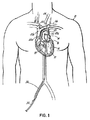
図中で類似の参照番号は同様な要素を表し、簡潔性のためこれらの要素は後の説明では特に記載したり説明したりしないことがある。図1は、患者10の心臓12を断面で示す患者10を図示する。カテーテル30が大腿部や腸骨領域のような鼠径部の動脈36を通り抜けて示され、カテーテル30の遠位端で拡張せず縮んだ状態に示される物理偏流装置50を運搬する。心臓12は、左心房14から僧帽弁16を通って左心室17への血流を受け入れる。その後血液は、大動脈弁18を通って大動脈20へと圧送される。大動脈20は、上行部分20aと弓あるいは曲がった部分20bと下行部分20cとを含む。3つの弓血管22、24、26は、一般的に弓20bで大動脈20から始まる。これらの弓血管22、24、26を通る血流は、酸素を豊富に含んだ血液を患者の脳や上肢に向かわせる。種々の塞栓偏流装置の例が本書で示され、説明され、それぞれの偏流装置は、特定の患者に対し永久的にあるいは仮設的に代替的に用いることができる。たとえば仮設的な使用は、塞栓を偏流することが医学的治療の間だけ必要な状況で好ましく、血液の流れに除去する物質が流れる危険がある治療などのときである。本書で説明される偏流装置(単数あるいは複数)50および他の装置は、患者のいかなる体内でも、動脈の枝管経由であるいは動脈中へ刺すことにより動脈樹中へ、最少の侵襲で導入できることが分かる。本書で説明する偏流装置は、切開手術に代わって、あるいは、より少ない侵襲で、ロボットの方法や最少の侵襲処置やキーホール処置により埋め込むことができる。カテーテルの使用について、いかなるカテーテル導入処置の後に、たとえば代表的なオーバーザワイヤ法のようなカテーテルを配置するのを容易にするガイドワイヤの使用を含んでも、血管内の組織に導入する間は偏流装置50を最初につぶしておいて、それから正しく配置されたら起動し拡張してもよいことは理解されよう。偏流装置は偏流装置50を大動脈内の適切な位置に保持し搭載する適切な構成、たとえばステントやフックやバネのようなバイアス要素を有していてもよい。
In the drawings, like reference numbers indicate like elements, and for the sake of brevity these elements may not be specifically described or described in later descriptions. FIG. 1 illustrates a patient 10 showing the
図2Aは、心臓の上部、大動脈の曲がった領域すなわち弓20bおよび3つの弓血管22、24、26の拡大断面図を示す。図はさらに拡張した偏流装置50を示し、偏流装置50は、心臓12からあるいは心臓12を通る、すなわち大動脈弁18と大動脈20を通過して下方に向かう、すなわち大動脈20の下行部分20cへ向かう塞栓物質を、各弓血管22、24、26の入口22a、24a、26aから下流へ偏流させあるいは導く。図中に示す生体構造は、明確な図解のために単純化していることに注意を要する。図解した生体組織の種々の部分、たとえば弓血管入口22a、24a、26aは実際にはより複雑な様相と詳細とを有する。血流中の物質、たとえば固体や気体の物質は、弓血管22、24、26を経由して脳に入り込む強い傾向を有する。腕頭動脈22(右頸動脈と右鎖骨下動脈へと至る)、左頸動脈24および左鎖骨下動脈26は全て心臓22からの比較的直接的な流路を有し、それゆえ、心臓12からの血流中の物質はこれらの血管を通って脳に入り勝ちである。偏流装置50は血液を弓血管22、24、26を通過するようにするが、血液は、偏流装置50内のチューブ52を通過して、逆行するように弓血管22、24、26に向かって戻るので、血液は依然として脳へ流れる。一方、血流内の塞栓物質は方向を変えることが少なく、体内の下方部分への下方の流路を流れ続けることが多い。脳以外の組織は、塞栓が入ってもより許容する。たとえば、塞栓が脚や肝臓に入っても危険は遥かに少ない。
FIG. 2A shows an enlarged cross-sectional view of the upper part of the heart, the bent region of the aorta, ie the arch 20b and the three
図2Aに示す偏流装置50は、種々の長さで形成され、種々の長さの大動脈20内を覆いまたは延在する。弓血管22、24、26を通って脳に流れる血流は偏流装置50によって制限されることはなく、高い圧力勾配を生じて遠位の大動脈への血流を妨げるほどに偏流チューブ52は細くはない。偏流装置50は、ステント取付けチューブに類似の方法で形成される。ワイヤメッシュタイプの取付け54が示されるが、取付けはワイヤメッシュタイプステントと対照的なコイルでもよく、あるいは、他の適切な代替または追加の取付け特徴を有してもよい。種々のタイプの大動脈ステントグラフトを使用でき、ジグザグ形状のワイヤ、あるいは、他の半固定支持構造などを含む。たとえば、そのような支持構造は、本願の図18、19、20にグラフトとして示される。適切な大動脈ステントグラフトは、ダブリュー・エル・ゴア・アンド・アソシエイツ社(W. L. Gore and Associates, Inc.)やクック・グループ社(Cook Group, Inc.)などの会社から入手可能である。偏流装置50は、プラスチックやステンレスあるいはニチノールなどの金属のような、生体適合性材料から形成される。チューブもまた、ダクロン、テフロン、ゴアテックスなどの布地を含む生体適合性材料、あるいは、ウシ、心膜あるいは組織工学によって作製された材料のような生物由来材料である。選択された材料は、凝固抵抗特性を含み、血流の高い剪断応力あるいは流れの停止の領域を防止する特徴を有する。種々のコーティングや表面処理(表面を粗くするなど)を適宜用いて、その特性からの利点である埋め込み領域で組織が内方成長するようにする。大きくなりすぎた表面では、血液に対して生物由来表面を提供するので、凝固しにくい。凝血塊やたんぱく質の集積等の形成を防止するコーティングを用いてもよい。これには、ヘパリンや他の凝血塊防止剤などの種々の抗凝血剤を含む。
The
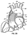
図2Bは、凝血塊や他の塞栓を弓血管22、24、26から離れる方向にする偏流装置70の他の構成を示す。偏流装置70もステントタイプ装置として示され、装置70のワイヤメッシュあるいはコイル74に取り付けられる物理偏流部分すなわち傾斜(ランプ)72を含む。再度、ステントタイプ装置70は、保持の目的のために他の取付け構造で代替されても、それらを含んでもよく、あるいは、作動中はその位置に縫合されてもよい。偏流構造72は、本書で参照される他のタイプの塞栓偏流あるいは方向変換構造と同様に、図18〜20に示される外科的置換グラフトの、特に限定のない例に組み込まれる。また、棘状突起あるいはフックを用いて偏流装置70を大動脈20に固定してもよい。図2Bに示す偏流装置70の一つの利点は、弓血管22、24、26の入口22a,24a,26a上を覆ったり物理的な障害となるものがないということであり、血流の妨害の危険性が低いということである。物理偏流部分72の高さ、角度、長さ、位置およびパターン(直線傾斜、曲線傾斜など)は適切なように変化してよい。この装置70で目的とすることは、血流中の物質が弓血管22、24、26への入口22a,24a,26aを越えて通過するように塞栓76を偏流させることである。事実上、脳への血流のほとんどは最初の2つの弓血管(すなわち、腕頭動脈22と左頸動脈24)から生じ、これらの2つを保護することは最も高い頻度で優先される。偏流装置70は馬蹄形状を有し、弓血管(不図示)の横方向に位置する。卵形でもよく、弓血管は卵形環状形状の中心と連通するようになる。
FIG. 2B shows another configuration of the drift device 70 that directs clots and other emboli away from the
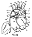
図2Cは物理偏流チューブ92とステントタイプの取り付け部分94を含む別の代替の偏流装置90を示す。チューブ92は、血流を一般的に旋回運動に方向変換させあるいは強制する一般的に螺旋形状要素96を含む。血液が大動脈弁18から出るとき、その流速は弁18の半径方向外側部分および大動脈20より弁18の中心部分で高い。螺旋形状要素96は、チューブ92の入口92aから見ると右巻きすなわち時計方向の螺旋に見えるが、螺旋は逆巻きでもよい。血液が大動脈弁18から出ると血液の流れには自然な螺旋がある。下方から見ると、血液は右手回りを示す。この自然な螺旋流れを増やすことが、この種の塞栓偏流あるいは方向変換を行うのに最も簡単な方法であろう。血液中の物質は螺旋あるいは渦流れの中心を進行する傾向があり、したがって、血液に螺旋流れを与えることが血液中の物質あるいは塞栓を流れの中心に向かわせることになる。よって、螺旋の血流は、物質あるいは破片が弓血管22、24、26に入り込むよりも大動脈20の中心に留まるようにする。曲線のチューブ状部材92の助けと一緒に螺旋形状要素96は、塞栓粒子あるいは物質がチューブ92から出て、大動脈の中心に留まり、塞栓粒子あるいは物質が弓血管22、24、26の入口22a、24a、26aに向かって戻ることを防止することを確実にする。
FIG. 2C shows another
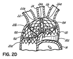
図2Dは、螺旋要素102を含むが、バイパスチューブを使用しない装置100の別の実施の形態を示す。その代わり、一般的に螺旋形状要素102(単数あるいは複数)は、血液を継続的に螺旋状にして、よって、物質や粒子が大動脈20内の血流の中心となるようにし、大動脈20の上側あるいは弓20bで接続する弓血管22、24、26から離れるようにする。ステント状の取付け部材104はオープンメッシュでもよく、専用開口を有して、そこを血流が通って弓血管22、24、26に流れるようにしてもよい。
FIG. 2D shows another embodiment of a
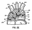
図2Eは、ステント状の構造104に取り付けられた、連続的な偏流部材とは逆に、一組の偏流板102を含む偏流装置110の別の実施の形態を示す。一組の偏流板102は、大動脈20内の曲がり20bを通って粒子や他の塞栓物質が血流の中央に留まるように設計され、これまでの実施の形態と同様に、物質を脳の外に保つ「スピードバンプ」として作用する。
FIG. 2E shows another embodiment of a drift device 110 that includes a set of
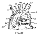
図2Fは、大動脈20の曲がり20bを通る血液の一般的に螺旋状の流れを促進する偏流装置120の別の実施の形態を示す。ここで、多数管腔チューブ122は一般的に螺旋状に形成され、ここでも螺旋が時計方向あるいは半時計方向に曲がりあるいは回転し、所望の一定のあるいは一定でない任意のピッチでよい。他の実施の形態と同様に、この物理偏流部分(たとえば、本実施の形態のチューブ122)は大動脈20中でいかなる所望の方法で取り付けられてもよいが、ステント状の拡張メッシュ要素124が説明のために再度示されている。螺旋は粒子あるいは物質を、上方向に戻って弓血管22、24、26を通って脳に進行するよりも、大動脈20中の曲がり20bを通って下方に移動するように保つ。この特徴は、血流の危険性の高い部分(すなわち、粒子や他の塞栓をより含みがちな血流の中央)を取り扱う原理をも示し、その部分を弓血管22、24、26の入口22a、24a、26aの入口の下流の遠位の下行大動脈20Cにそらす。
FIG. 2F illustrates another embodiment of a
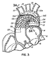
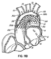
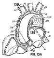
図3は、ステント内のあるいは他の取付け構造に接続されるチューブの使用を含まない物理偏流装置130の別の実施の形態を示す。その代わり、遮蔽部材132が取付け部材134に取り付けられ、取付け部材134はこの図示の例でもステント状部材であるが、他の適切な取付け構造でよい。遮蔽部材132は、図3の断面図で最もよく示されているが、弓血管22、24、26の入口22a、24a、26aのそれぞれと連通する開口上部部分132aを有する部分的チューブ構造をしており、その部分的チューブ構造は開口入口132bを有し矢印136で示される血液の逆流を受け入れる。粒子や他の塞栓は入口132bに逆戻りし弓血管22、24、26へと上方には流れにくい。さらに、粒子や他の塞栓138がこの逆戻りをしたとすると、左鎖骨下動脈26に最も入りやすく、結果として脳の損傷を引き起こしにくい。遮蔽部材132は大動脈20を流れる血流を曲がり20bの周囲で遠位の下行大動脈20cに向けて維持するが、十分な血流が弓血管22、24、26を経由して脳へ流れるように、構成される。遮蔽部材132の前方すなわち上流端132cは、第1弓血管22の起点すなわち入口22aの上流でほとんどシールされあるいは大動脈20の壁に合わせられ、この位置で流れる血液が、塞栓を運搬している可能性を有して遮蔽部材の下部を通って流れ脳に到達することがないようにする。たとえば、フランジ型の縁および/またはガスケットとしての生体適合性材料が使われて、遮蔽部材132の少なくともこの位置132cでシールを提供する。図3Aは、図3の断面であり、チューブ状構造を示すが、他のいかなる形状、たとえば、かなり平らな形状、あるいは、図3Aに示す連続的な曲面とは逆に直線状の壁を有する形状などを用いてもよい。さらに、チューブ状構造132は、図示のように、弓血管22、24、26の入口22a、24a、26aに隣接してわずかな縁だけを覆うのとは逆に、大動脈20の内壁の広い表面積と接触しあるいは覆ってもよい。チューブ状構造132の縁全体が大動脈組織と接触しないならば、少なくとも位置132cでシールをすることが好ましい。このことは、チューブ状構造132と大動脈20の間の密着を維持すること、および、組織の入り込みを促進する、多孔性グラフト材料、あるいはステント構造、あるいは折り畳まれた金属構造(たとえば、心房中隔欠損閉塞材)を用いることにより容易にされる、組織を内方成長させることにより達成できる。
FIG. 3 illustrates another embodiment of a
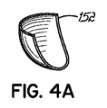
図4と図4Aは、弓血管22、24、26へのより多くの血流を確実にする物理偏流装置150の実施の形態を示す。特に図4は、各血管22、24、26への入口22a、24a、26aの上に隣接して配置される一組の偏流要素152を示す。これらの偏流要素152は単一の「スピードバンプ」偏流板よりも低い形状をし、順番に「ハンド・オバー・ハンド」の一組の偏流板でよりよく保護して、物質を脳の外に保つ。偏流要素152はステント状装置154に取り付けられるが、本書で説明された他の実施の形態についてと同様に、他の方法で取り付けられてもよい。図4および図4Aは一つの可能な形状を示すが、多くの別の形状を偏流装置150に用いてもよい。埋め込み後にこれら偏流要素152が位置を変えても、このことは血流をあまり妨害したり邪魔したりせず、偏流要素152は弓血管22、24、26と整列する必要はない。たとえば、偏流要素152は弓血管22、24、26への1つあるいは複数の入口22a、24a、26aを、その入口をさえぎることなく、またいで位置してもよい
4 and 4A illustrate an embodiment of a
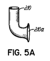
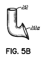
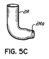
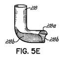
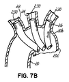
図5、図5A〜E、図6、図7Aおよび図7Bはそれぞれ、弓血管22、24、26へのそれぞれの入口22a、24a、26aの各々に挿入され取り付けられる個々のチューブ状偏流要素の種々の実施の形態を示す。チューブ状要素の各々は、血流入口と血流出口端とを備える。各チューブ(チューブ状偏流要素)の出口端はそれぞれの弓血管22、24、26へ延在するが、入口端は大動脈20内に延在する。チューブの曲がりは大動脈中の入口端の適切なあるいは所望の距離下流に位置し、粒子はチューブ状部材により偏流され、向きを変えてチューブの1つの入口に入るのとは反対に血流の中にあり続ける傾向がある。図示の実施の形態では、弓血管22、24、26のそれぞれは別々の1つのチューブで保護されるが、弓血管22、24、26の1つ以上が、別のチューブで保護されてもよい。別々のチューブ180は図5に示すように個々に取り付けられてもよいし、チューブ190が図6に示すステント状装置のような共通の取付け構造194に取り付けられてもよいし、あるいはチューブ200と取付け構造204を示す図7Aに示すように取り付けられてもよい。それらの図面に示されるように、チューブは弓血管のそれぞれから所望の長さだけ大動脈中へ延びてもよい。さらに、チューブの入口端は種々の形状をしていてよく、たとえばこれらの図面で例として示される形状や、他の形状でよい。たとえば、チューブの入口端は平らでも、トランペット形でも、角を有していても、種々の他の特徴や形状を含んでもよい。溝を表面に加えて、血流を好ましいように方向付けてもよい。図5Aはトランペット形入口210aを有するチューブ210を示す。図5Bは、入口端212aが上方にカーブしすなわち角度を有するチューブ212を示すが、カーブした端部は下向きでもよく、あるいは上向きと下向きの両方でもよい。図5cは、たとえば図5を参照して前に説明したように弓血管と接続するために弓血管内に挿入できるチューブ214の別の実施の形態を示すが、注入口すなわち血液の入口214にテーパが付いている、すなわち、チューブ214の隣接する部分に比べて直径が減少している入口214を有する。図5Dは別のチューブ216の上面図であり、血液偏流要素あるいはバッフル構造216bを有する血液入口端216aを有し、たとえば図5の関係で前に説明したように、チューブ216が弓血管と結合されているときに、血液がチューブ216を通過するときに血液を入口端216aから離れるように偏流させる。図5Eは、図5に示されるのと類似のチューブ218の別の実施の形態を示すが、例示するへこんだ窪み218b付きのたて溝付き構造を有する血液注入端218aを備える。これらのたて溝あるいは窪み218bを用いて血液を偏流させ、あるいは、血液が入口端218aを通過するときに、利点のある血流特性を与え、塞栓物質が入口218aに流れ込んで弓血管の一つに入り込むことがないことをさらに確かにする。図7Bのチューブ230で示すように、1つあるいは複数のチューブを下行大動脈により深く延在させてもよい。この構成では、血液が下行大動脈20cから頂部へ逆流する必要があり、粒子や他の塞栓は弓血管22、24、26へ入るのに180°曲がらなければならない。図7Cは、各弓血管22、24、26内の複数のチューブ部分240a、240b、240cが単一チューブ242に一緒に接続することを示し、単一チューブ242は、逆流が必要な入口端242aを有する。図示はしないが、血流に面する各チューブの先頭すなわち上流端は、縁や表面に角度をつけたりボートの舳先のように曲面形状にしたり、より空力学的あるいは流体力学的に形成される。この先頭縁は、血液が平面や粗い面と衝突することにより生ずる血球破壊のように傷つくことなしに流れ過ぎるように、溝付であったり他の特徴を有していてもよい。そのような構成は、粒子や他の塞栓がチューブの側を流れ過ぎ、下行大動脈20cへと流れ続けるようにもする。各弓血管22、24、26内の一組のチューブは、特定の状態に応じてあるいは必要とされるように、それぞれ異なった形状とサイズでもよい。チューブ用に選定された材料もまた、金属、非金属、金属と非金属との組合せ、生物学的あるいは人工的材料など、いかなる生体適合材料でもよい。本書で説明した全ての実施の形態と同様に、繊維状内方成長を促進する材料を使い、異物(たとえば、チューブや他の偏流部材)が患者の自然な組織の一部になるのが好ましい。
5, 5A-E, 6, 7A and 7B respectively show individual tubular drift elements inserted and attached to each of the
本書で示し説明した種々のチューブは多くの別の形態で構成されてもよい。たとえば、収縮した状態と拡張した状態の間を動き、予め形成されあるいはステントを拡張する動作の間に形成される曲がりあるいはベンドを有するステント構造として形成されてもよい。ステントは、大動脈中で覆われて弓血管内で開口しているように構成されてもよい。すなわち、ステント構造は、大動脈内に位置する部分の代表的な覆う材料を有し、弓血管内に置かれる、メッシュや他のワイヤケージ型構成のような、開口構造を有する。血液の収縮流により大動脈内でチューブ(単数あるいは複数)が崩壊しないように、ステントは、大動脈内にある剛性の高い長い部分と、弓血管の一つにあるより柔軟な部分(たとえば、オープンメッシュやワイヤゲージ)を含むように構成されてもよい。より一般的に言うと、ステントはその長さ方向に変化する強度あるいは剛性を有するように構成される。このことは異なる機械的構成を用いることによって達成され、たとえば、長さ方向の一部分に他の長さ方向の部分と比べて異なったワイヤ支持構成とし、および/または、長さ方向の一部分に他の長さ方向の部分と比べて異なった材料組成としたりする。チューブが大動脈内で崩壊しないようにする別の方法として、チューブの外壁と大動脈の内壁との間に延在する支持部材を用いることもできる。チューブは、大動脈自身によって上手く支持されるような別の方法で構成することもできる。たとえば、チューブは、以下に図8A〜8C、図9A、9B、あるいは図10A、10Bとの関連で説明するものと類似の支持特性を有する。別の可能性のある改変では、大動脈中にあるようになされるチューブの部分が、大動脈の内壁に隣接するフランジ、あるいは、大動脈壁と係合しチューブに全体的な強度を付加するための亜鈴形またはチューブの長さ方向に局所的に広がった円周部分と類似に形成されたチューブの広い部分を有する。支持を付加するために個々のチューブを連結してもよい。血行動態的な形状とされた前面あるいは上流端あるいは側面を用いて、血液がチューブに向かって流れるときの衝撃力を弱めてもよい。大動脈内の複数のチューブが互いに衝突するのを防ぐために、チューブが大動脈に配置されるときに互いに離れるようにベンドあるいは曲がりを有してチューブを形成してもよい。 The various tubes shown and described herein may be configured in many different forms. For example, it may be formed as a stent structure that has a bend or bend that moves between a contracted state and an expanded state and is preformed or formed during an operation of expanding the stent. The stent may be configured to be covered in the aorta and open in the arch vessel. That is, the stent structure has an open structure, such as a mesh or other wire cage type configuration, that has a typical covering material for the portion located within the aorta and is placed within the arch vessel. To prevent the tube (s) from collapsing in the aorta due to the contractile flow of blood, the stent can be a long, rigid part in the aorta and a more flexible part in one of the arch vessels (eg open mesh). Or a wire gauge). More generally, a stent is configured to have strength or stiffness that varies along its length. This is accomplished by using a different mechanical configuration, for example, having a different wire support configuration in one lengthwise portion compared to other lengthwise portions and / or other portions in the lengthwise direction. The material composition may be different from that of the portion in the length direction. Another way to prevent the tube from collapsing in the aorta is to use a support member that extends between the outer wall of the tube and the inner wall of the aorta. The tube can also be constructed in other ways that are well supported by the aorta itself. For example, the tube has support characteristics similar to those described below in connection with FIGS. 8A-8C, 9A, 9B, or 10A, 10B. In another possible modification, the portion of the tube made to be in the aorta is a flange adjacent to the inner wall of the aorta, or a dumbbell to engage the aortic wall and add overall strength to the tube It has a wide portion of the tube that is formed similar to a circumferential portion that extends locally in the shape or length of the tube. Individual tubes may be connected to add support. The front or upstream end or side of the hemodynamic shape may be used to reduce the impact force when blood flows toward the tube. To prevent multiple tubes in the aorta from colliding with each other, the tubes may be formed with bends or bends so that they separate from each other when placed in the aorta.
図8Aと図8Bは、取付け構造274に接続された偏流要素272を含む装置270の別の実施の形態を示す。この実施の形態では、取付け構造274はまたステント状であり、大動脈の内壁に係合し、装置を図8Aに示す位置に固定する。再度、他の全ての実施の形態と同様に、代わりにいかなる取付け構造も使用でき、棘状突起、フック、接着剤あるいは装置を十分に大動脈20内に固定する他の構造や特性などを使用できる。偏流要素272は、1つあるいは複数の弓血管22、24、26の入口とほぼ一致する張り出し(オーバーハング)を提供し、血流とその中の粒子あるいは他の塞栓を物理的にそらせる。偏流要素272は、血流を物理的にそらせて、大動脈20の曲がり20bを通る下向きの流れを促進し、それによって血流中の粒子や他の塞栓が弓血管22、24、26を通過するまで血流中の粒子や他の塞栓の下向きの流れを促進する。
8A and 8B show another embodiment of a
図8Cはステント状取付け構造274あるいは他の取付け構造を図8Bに示すのとは逆の方法で偏流要素272に接続することを示す。すなわち、図8Bでは偏流要素の内面にステント状構造すなわち要素274が接続されるように示されるが、ステント状構造274は偏流要素272の外面に接続するものとして示される。たとえばステント状構造274を偏流要素272の層の間に挟むことを含め、代わりに他の接続方法を用いることができることは理解されるであろう。ステント状要素274は大動脈20の組織と接触しておかれてもよく、ステント状構造は、組織がその中に成長するにつれ大動脈壁に基本的に埋め込まれる。
FIG. 8C shows connecting a stent-
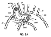
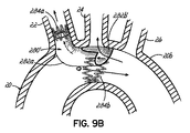
図9Aは、偏流装置280の別の代替の実施の形態を示す。この実施の形態は、弓血管22に収容されたパイプあるいはチューブ部分282aと、第1の弓血管22と次の2本の弓血管24、26に保護を与える大動脈20内に位置する張り出し282bとの合成を示す。多くの可能な代替の1つとして、図9Aに示す張り出し部分282b’は、図3Aに示したものに類似の閉じた空間を基本的に形成するように再構成してもよく、図9Bの装置280’に示される。これは、第2の弓血管22への上向きの開口を作るが、チューブ状部分282aを通って第1の弓血管22への血流も依然として残る。ステント状取付け構造284a、284bあるいは他の構造などの取付けは、弓血管22内および大動脈20内、あるいは弓血管22または大動脈20のいずれか内で用いられる。図9Aおよび図9Bに示す実施の形態には種々の利点があり、たとえば、大動脈20の内側への異物を減らし、物質上の凝血塊形成の危険性が少なく、装置280の移動やずれの危険性が少なく、埋め込みが簡単である。この最後の利点に関して、オペレータは弓血管22、24、26の一つへ入り、その後たとえば適当なカテーテルあるいは他の配備装置あるいは外科手術具から装置280を配備しなければならないだけであろう。
FIG. 9A shows another alternative embodiment of the
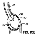
図10Aと図10Bは、ステント294で取り付けられ、弓血管22、24、26の1つあるいは複数を血流から隔離する偏流装置290の別の実施の形態を示す。すると、血流は遠位の大動脈弓あるいは下行大動脈20cから流入チューブ292へと供給される。流入チューブは、血液を弓血管22、24、26に流すための空間を作る隔離要素あるいは遮蔽296と連結あるいは連通する。塞栓は流入チューブ292に入るように流れ方向を逆にするのとは反対に大動脈20を下方に進行し続ける傾向があるので、流入チューブ292に入る血液が1つあるいは複数の粒子や他の塞栓を含む可能性はかなり少ない。この装置290は、切開外科手術手順用には別の構成とされてもよい。たとえば、弓血管22、24、26へは、流入グラフトにより塞栓物質が入り込む危険性の少ない大動脈20の一部からかん流されてもよい。これは、グラフトが弓20bへと戻るように導く下行大動脈20cにおいてでもよく、あるいは大動脈の横から、およびより具体的には弓20bの内側または上行大動脈20aの下方部分、おそらく大動脈のとても下の冠状動脈(不図示)でもよい。たとえば、グラフトの外側の曲がりから弓血管の分岐が始まるところで、弓血管22、24、26の代わりにグラフトがある。
FIGS. 10A and 10B show another embodiment of a
図11Aと図11Bは、ここでもステント状構造の形だが、取付け構造304に接続された遮蔽302を含む装置300の別の実施の形態を示す。再度、ステント状構造を他の適当な外科手術あるいはカテーテル配備取付け構造と置き換えてもよく、構造を大動脈20などの血管に固定するグラフトあるいは他の方法を含む。この実施の形態では、遮蔽部材302は、少なくとも片方の端部に流入口を有して用いられる。たとえば、図11Aでは単一の流入端部開口302aが上行大動脈20aの血流の外側あるいは周辺に示され、そこでは塞栓が流れに含まれている可能性は少ない。図11Bは、遮蔽302の対向両端部に流入開口302a、302bを示し、逆流の血流を弓血管のそれぞれと連通する空間302cに流す。下行大動脈20cと連通する開口302bは、塞栓の危険性の少ない追加の血流を可能にし、鼠径部から弓血管22、24、26および遮蔽302へのカテーテル手順を可能にするのに好適でありあるいは重要である。別の改変(不図示)では、大動脈基部からの流入を含み、注入流路の血液を空間302cに向け、弓血管22、24、26に、あるいは弓血管22、24、26と連通する1つあるいは複数の別の流出に導く。流入は、完全円構造あるいは部分的に輪状または円形構造でもよく、大動脈基部の全てあるいは一部を取り囲み、塞栓を含む危険性の低い位置からかん流する血液を直接引き込む。
11A and 11B illustrate another embodiment of a
図12は、上行大動脈20aの下部、大動脈基部に比較的近いが、大動脈弁の動作を邪魔しないところに位置する、流入端あるいは部分322aを有する遮蔽部材322を組み込んだ偏流装置320を示す。上記のように、大動脈20のこの位置は、大動脈20中の血流の流速特性のために、塞栓を含む可能性が少ない。たとえば、冠状動脈(不図示)がこの領域で大動脈20から始まり、弓血管より塞栓を受け入れる発生率は遥かに低い。装置320の遠位端322bは閉じて示されるが、遠位端322bは開口し、血液が弓血管22、24、26の入口22a、24a、26aへ後ろへあるいは逆流するように流れるようにし、また、鼠径部から血管造影法の研究を可能にする。装置320はステントタイプの取付け構造324と一緒に示される。
FIG. 12 shows a
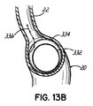
図13に示す改変は、大動脈20中の血流により少ない抵抗を示すチューブ状流路付き遮蔽332を有する装置330である。この図は、図12で示すよりも大きな流路あるいはチューブ状構造を示し、開口した遠位端332aを備える。大動脈弁18を通過した中央の血流は、流路332を通って、下行大動脈20cへと下がり、患者体内の低い部分へと進行する。周辺の血流は矢印336の方向に流路332の外側を弓血管22、24、26へと進行する。装置330はここでも、例としてステント状の取付け構造334と一緒に示される。
The modification shown in FIG. 13 is a
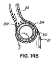
図14Aと図14Bは、大動脈20のより中央に位置し、大動脈20の曲がり20bを通るチューブ状流路構造352を有する偏流装置350の別の実施の形態を示す。この装置350は、塞栓をより多く含んでいるであろう中央の血流をチューブ352に流し下行大動脈20cに流出させ、一方、チューブ352周りの十分な血流を、チューブ352を大動脈20内のほぼ中央に取り付ける適当な取付け構造354を通過し、弓血管22、24、26へと流す。再度、取付け構造がチューブ状構造352の周囲の血流を弓血管22、24、26へ流し、一方、粒子や他の塞栓を、下行大動脈20cへと下方に運び弓血管22、24、26の入口22a、24a、26aを通過するのが確かな血流にそらす限り、いかなる適切な取付け構造を用いてもよい。
14A and 14B show another embodiment of a
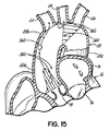
図15は、上行大動脈20aの下部と大動脈弓20bの曲がりで一般的に示された理論的血流流速特性を有する血流中の塞栓360の可能な経路を模式的に図解する模式図である。この点について、上行大動脈20aの下部の高速な中央の流れの塞栓は大動脈の外側、上部の壁に向けて上方に向かい、弓血管22、24、26の1つに直接入り込む。
FIG. 15 is a schematic diagram that schematically illustrates possible paths of an
図16は、図15に類似した図だが、大動脈20を通り弓血管22、24、26へ入る高速血流の可能性の高い領域を示す色が濃い領域を表示する。
FIG. 16 is a view similar to FIG. 15, but displays a dark-colored region indicating a region with a high possibility of high-speed blood flow that passes through the
図17は、3つの別々の弓血管22、24、26用の3本の分岐402、404、406を有するグラフト400を示す。図17〜20、21A、21Bは、支持ステント構造と一緒に用いあるいは用いられない種々の形のグラフトを示す。図17は、大動脈弓を形成する部分と弓血管22、24、26に接続するそれぞれのチューブ状部分402、404、406を有する従来型のグラフト400を示す。図18は、下行大動脈20cからの反転したあるいは逆流血流をチューブ412を経由して弓血管に向けるグラフト装置410を示し、チューブ412は、それぞれ弓血管(不図示)に接続する3本の分かれたチューブ上部分412a、412b、412cへ分岐する。装置410は従来型のジグザグ型ワイヤ支持構造410aと一緒に示されるが、本書で開示するように外科手術グラフトの実施の形態ではそのような支持の必要はない。再度、ワイヤ構造のような支持構造付きあるいはなしの動脈ステントグラフトを開示されたあるいは本開示により違ったように包含されたどの実施の形態で取付け構造として用いてもよい。
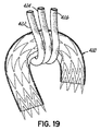
FIG. 17 shows a
図19は、グラフト装置420の別の実施の形態を示し、この装置では注入が大動脈弓の内側から取られる。大動脈弓の内側では、血流中に塞栓が含まれる機会は少ない。この実施の形態では、3つの弓血管(不図示)に別々に接続する3つの別々のチューブ422、424、426を図示する。単一のチューブが大動脈弓の内側の位置に接続し、それからそれぞれの弓血管に接続する3本のチューブ状部分に分岐してもよいことは理解されよう。
FIG. 19 shows another embodiment of a graft device 420 in which injection is taken from the inside of the aortic arch. Inside the aortic arch, there is less chance of embolization in the bloodstream. In this embodiment, three
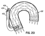
図20は、図19に類似の装置430の実施の形態を示すが、注入チューブ432、434、436が上行大動脈の下部位置に通ずる。この領域は、冠状動脈の起点に近く、塞栓の危険性が低いと思われる。
FIG. 20 shows an embodiment of a
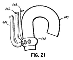
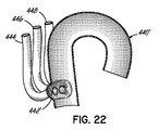
図21は、自然なバルサルバ洞、すなわち大動脈弁の弁尖の後ろの領域をシミュレートする膨らみ部442を有する大動脈グラフトを示す装置440の別の実施の形態を示す。図21は完全に環状の膨らみ部442を示すが、図22に示す別の代替の装置440’は、膨らみ部442’は完全な環状である必要はないことを示す。再度、図21と図22の実施の形態は、血液中の塞栓の危険性の低い大動脈弁の弁尖の近傍の大動脈20の下部からチューブ444、446、448への血液注入を取る。チューブ444、446、448は、弓血管(不図示)に接続する。
FIG. 21 shows another embodiment of a
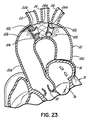
図23は、自然な大動脈弁18から下流の位置に1つあるいは複数のバルブ構造472を追加することを含む装置470の別の実施の形態を示す。このことは、自然の大動脈弁18に付随する流れの動力学に利点を有するが、弓血管の入口22a、24a、26aの近くの位置においてである。バルブ構造472は、自然の大動脈弁18に類似に見えるように模式的に図示されており、一方向チェッキバルブと類似の方法で作動する1つあるいは複数の可動フラップのような、1つあるいは複数の可動バルブ要素を含んでもよい。バルブ構造472が自然の大動脈弁18と類似の方法で作動、すなわち開閉するように構成されるならば、自然の大動脈弁18により生ずる特性と類似の血流流速特性が、少なくとも入口22a、24a、26aの1つの近傍の1つあるいは複数の位置で、形成される。高速の中央の流れは塞栓を含む可能性が高く、したがって、塞栓は弓血管22、24、26の入口22a、24a、26aから離れて通り過ぎるように向けられ、一方、バルブ構造472の半径方向の外側あるいは周辺位置の低速の血流は弓血管22、24、26への血流を提供する。よって、図23に模式的に示される1つあるいは複数のバルブ構造472は大動脈20の弓20bに置かれてもよく、高速の流れを弓20bの半径方向の中心に向けて、大動脈20の周辺の流路をたどって弓血管22、24、26に入り込む可能性があるのとは反対に、塞栓が大動脈20の曲がりすなわち弓20bを通る半径方向の中心の血流流路をたどり下行大動脈20c中へ下がるようにする。この種のバルブ構造472にとって、自然の大動脈弁18が閉じるように、完全に閉じることは必要ではない。逆流の血流が生じるようにすることは、このことが一般的に冠血流がどのように生ずるかであるので、有用である。完全に閉じるバルブは、冠状動脈への血液流を制限するであろう。1つあるいは複数のバルブ472は、大動脈弓20bの領域のどこに用いてもよく、図23に示すステント状構造474あるいは他の構造や特性など、どのような方法で取り付けてもよい。
FIG. 23 illustrates another embodiment of a
図24は図23に類似の装置490の別の実施の形態を示すが、中央導管すなわちチューブ状構造492を追加して、塞栓を下行大動脈20cへとさらに向かわせ弓血管22、24、26を通過させる。再度、ステント状の取付け構造494が説明の目的で示される。この装置では、バルブ472を装置490の入口で使って、塞栓を含む可能性の高い高速周辺流を中央にする。塞栓を含む可能性の低い低速流は、矢印496で示されるようにチューブ状構造492の周囲を流れ弓血管22、24、26へと流れ込む。装置490の近位端および/または遠位端に開口が設けられ、この周辺の低速血流をチューブ状構造492の周囲に、そして弓血管22、24、26へと流れるようにする。導管は下部でバルブ472に接近して配置され、導管492の周囲の流れが、粒子や他の塞栓は追随するのが難しい一般的にS字型経路の少なくとも2回の曲りをするようにする。導管すなわちチューブ状構造492の外側の血流は、したがって、粒子や他の塞栓498をより含まなくなる。この装置490は経皮的に導入され大動脈弓20bの近くに配置され導管に取り付けられ、あるいはこれも他の実施の形態と同様に、他の方法の外科手術で埋め込まれてもよい。
FIG. 24 shows another embodiment of a
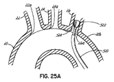
図25Aと図25Bは、装置を配置する間に塞栓を防止するのに重要な手続き方法に加え、どのようにカテーテルを用いてこれらの装置を挿入するのかを説明する。カテーテル520はステント522(少なくとも大動脈20の本体内に位置する部分において塞栓の通過をさせない)を供給しているものとして示される。図示のステント522は、自己拡張性(頸動脈治療で用いられるステントと同様)であるが、代わりにたとえばバルーン拡張してもよい。アテローム性動脈硬化物質524が、大動脈20から上がる時にオリフィスあるいは弓血管22、24、26の入口22a、24a、26aの周りにたまるのはごく普通のことである。その物質は大動脈から血管の起点の周辺の周りにあることが多いが、血管内に広がることもまた多い。この領域の操作は破片を取り外し、その破片は次に脳へと移る。脳へ供給する血管にステント522を、この疾患となる可能性が高い領域を越えて、供給することにより、ステント522は最初は疾患の領域を避ける。次にステント522は、脳への流れを「塞ぐ」(少なくとも一時的に)ように、部分的に配置される。ステントがより手前に配置されると、プラークから取り除かれた破片は、ステント522で押しつぶされるので、頭部へは移動しない。すると解放された物質は体の下部へと遠位に移動し、脳への移動は回避される。装置(たとえば、チューブあるいはステント522)の適用の順番は塞栓の危険性を最小にしなければならない。可能な限り、装置をより近位の血管に加える前に、より遠位の(すなわち、血流方向に関して下流)の血管に装置を置くのが好ましい。図25Bでは、鎖骨下血管24を最初に処理し、次により近位の左頸動脈血管26が2番目に処理される。真ん中の弓血管24を扱っている時に破片が取り除かれても、左頸動脈血管26に入り込みにくい。
FIGS. 25A and 25B illustrate how to insert these devices using a catheter in addition to the procedural methods important to prevent embolization during device placement.
図26は、弓血管22に挿入された塞栓予防装置554の使用を説明する。前に説明したように、弓血管22の起点すなわち入口22aの周囲の領域はかなりの疾患を有することが多い。より遠位の血管の前に上流側の血管を処置しなければならないと、あるいは、遠位の塞栓をそらすことがより近位の装置の挿入をより難しくするならば、解放された破片がより遠位の弓血管に入らないようにすることをアドバイスする。図26では、そらせ装置すなわち偏流要素あるいは装置550が腕頭動脈22に配置されるところである。破片の一部552が除去され、血液の流れでより遠位へ運ばれていることが示される。物質552が脳へ移動するのを防ぐために、塞栓予防装置554が次の2つの弓血管24、26を覆って置かれる。塞栓予防装置554はカテーテル556から供給されるところで示される。塞栓予防装置554は破片552を通過させない。それは完全に血液を通さない(この場合脳への流れは一時的に塞がれる)、あるいは、装置554は血液は通すが大きな物質は通さない。脳は、永久的なダメージを受けることなく短時間の血流減少には耐え、塞栓予防装置554は、重大な結果を伴わずに完全にあるいは部分的に血流を減少することができる。保護カテーテル556は、手続きが完了した後に取り除かれる。
FIG. 26 illustrates the use of the
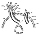
脳血管の分岐のパターンには多くの正常な変形がある。大部分で、大動脈弓は、本書で説明するように3本の血管22、24、26へと立ち上がる。一つの適度に一般的な変形が図27に示され、大動脈20からは2本だけの血管22’、26が立ち上がる(たとえば、ウシで見られるパターンで、よって、ウシ大動脈パターンとよばれることが多い)。この状況では、左頸動脈24’は、起点すなわち入口22a’を越えた腕頭動脈22’からその起点をとる。前記の塞栓予防装置はこの左頸動脈分岐24’への流れを妨害した。よって、偏流装置560は、装置560の開口部分562を通る向きの矢印で示されるように、この側部分岐24’へ流れが可能であると示される。一般的に、本書で説明する偏流要素は大動脈20の部分で通さないようにする必要があるだけである(すなわち、目標の弓血管の内側では通さないようにする必要はない)。この目的を達成するには多くの方法がある。ステントが覆われることもできるし、ステントがその製造により血液を通さないようにすることもできるし、ステントが、ステントの間の空間を閉じるプラスチックや他の物質を有することもできる。
There are many normal variations in the pattern of cerebrovascular bifurcation. For the most part, the aortic arch rises to three
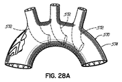
ある患者では、大動脈全体がかなり疾患しており、脳塞栓の進行の危険性がある。実際に、重度に疾患した大動脈は、年長者で精神作用の衰退に関連している。このような患者では塞栓の繰り返しの発現が、精神的衰退を引き起こす再発性の脳損傷という結果を生ずることは大いにありうる。図28Aと図28Bに示す装置570は、塞栓偏流装置(ここではチューブ572として示されるが、前記した装置のように他のいかなる適切な構成で代替することができる)と、大動脈全体に新たに裏張りするチューブグラフト574とを組み合わせる。このことにより、大動脈を装置570に覆われる流れから除外する。よって、この領域からの物質は、グラフト574の下に捕らえられるので、塞栓を起こすことがない。他の源からの塞栓はそらされる。
In some patients, the entire aorta is quite ill and there is a risk of progression of cerebral embolism. Indeed, a severely diseased aorta is associated with a decline in mental effects in older people. In such patients, repeated embolism can most likely result in recurrent brain injury that causes mental decline. The
図28Bは、この装置570が挿入のためにどのようにカテーテル580に収められるかを示す。この装置はその後に動脈系に移され大動脈の弓の近くに進められ、そして配置される。装置の分岐が弓血管に適切に入ることを確実にするために、ガイドワイヤを塞栓予防装置570の各分岐すなわちチューブ527に通し、それらを適切な目的血管に方向づけることは有用である。それらのガイドワイヤはその後装置570の各部すなわち肢を適切な分岐血管に方向づける。代わりに、装置570の各分岐572は、個々のシースあるいはカテーテルで供給されてもよい。別の有用な変形は、弓血管内に置かれる装置50の分岐572を大動脈グラフトの中で渦巻き状にすることである。主要な大動脈を覆う要素は、最初に所定の位置に挿入される。装置570の分岐572は主要なチューブ部分の内側に最初に位置し、それから弓血管の内側の最終的な位置に外側に反転しあるいは拡張する。これが、挿入を簡単にする。
FIG. 28B shows how this
配置用に分岐血管内に位置する要素の一部で、大動脈内に位置する偏流装置570の一部を渦巻き状にすることもできる。それから、大動脈成分は裏返しされて、大動脈の内側に位置することができる。これらは、別々に行われてもよいし(たとえば、チューブ状偏流装置がこのように個々に置かれてもよい)、図28に示すように装置570と一緒に行われてもよい。別のオプションは、その場で装置570を作ることである。弓グラフトは、予め形成された穴付きで、あるいは、その場で穴を形成して、大動脈に運ばれる。それから塞栓予防成分が、脳保護要素を運ぶことにより、追加される。
A part of the
同様の作用の結果は、弓血管のそれぞれに最初に個々のチューブを配置することにより、得ることができる(図25などに示すように)。それから、覆いのグラフトは上行大動脈と大動脈弓におかれる。チューブは、大動脈ステントが塞がれないように十分に長くなければならない。これは、基本的にこのアイデアと図28Aに示すチューブとを組み合わせたもので、1つの流路に2つのステントを有するクラッシュテクニック(crush technique)と呼ばれる。 Similar effects can be obtained by first placing individual tubes in each of the arch vessels (as shown in FIG. 25, etc.). The covering graft is then placed in the ascending aorta and aortic arch. The tube must be long enough so that the aortic stent is not blocked. This is basically a combination of this idea and the tube shown in FIG. 28A, and is called a crush technique with two stents in one channel.
本発明は種々の好適な実施の形態により説明されたが、また、これらの実施の形態はある程度詳細に説明されたが、添付の特許請求の範囲をそれらの詳細に制限したり、いかなるようにも限定したりすることは出願人の意図ではない。さらなる利点や改変は、当業者にとっては容易に分かるであろう。本発明の種々の特徴は、使用者の要求や希望により、単独であるいは組み合わせて用いることができる。これは、現在分かっているように本発明を実施する好ましい方法にしたがって、本発明を説明したものである。しかし、発明そのものは、添付の特許請求の範囲によってのみ定義される。 Although the present invention has been described in terms of various preferred embodiments, and these embodiments have been described in some detail, the appended claims are limited to such details or in any manner. It is not the applicant's intention to limit the content. Additional advantages and modifications will be readily apparent to those skilled in the art. Various features of the present invention can be used alone or in combination depending on the needs and desires of the user. This is a description of the present invention according to the preferred method of practicing the present invention as currently known. However, the invention itself is defined only by the appended claims.
Claims (45)
前記患者の前記大動脈に少なくとも部分的に配置されるようになされる物理偏流要素と;
前記物理偏流要素に連結される取付け構造であって、前記大動脈あるいは前記大動脈に連通する弓血管の少なくとも一つと係合するようになされる取付け構造とを備え;
前記物理偏流要素は、血流中の塞栓物質が前記1つまたは複数の弓血管を通過して前記大動脈の前記下行部分に流れるように、前記大動脈中の血流を方向づけるように構成され配列される;
装置。 An apparatus for preventing a stroke due to an embolic material in a patient's bloodstream, wherein the patient has an aorta having an ascending portion and a descending portion and one or more arch vessels communicating with the aorta that flows blood to the patient's brain. Has:
A physical drift element adapted to be at least partially disposed in the aorta of the patient;
An attachment structure coupled to the physical drift element, wherein the attachment structure is adapted to engage at least one of the aorta or an arch vessel communicating with the aorta;
The physical drift element is configured and arranged to direct blood flow in the aorta so that embolic material in the blood flow passes through the one or more arch vessels and flows to the descending portion of the aorta. ;
apparatus.
請求項1の装置。 The physical drift element further comprises at least one tube member;
The apparatus of claim 1.
請求項2の装置。 The tube member bends substantially along the aortic arch;
The apparatus of claim 2.
請求項2の装置。 The tube member is adapted to be mounted in one of the arch vessels communicating with the aorta, a portion of the tube member extending into the aorta;
The apparatus of claim 2.
請求項2の装置。 The tube member further comprises a plurality of tubular portions;
The apparatus of claim 2.
請求項2の装置。 The tube member comprises at least one non-tubular portion;
The apparatus of claim 2.
請求項1の装置。 The physical drift element further comprises a shielding member configured and arranged to shield an entrance to at least one arch vessel and redirecting blood flow away from the entrance;
The apparatus of claim 1.
請求項7の装置。 A tubular member coupled to the shielding member, the tubular member allowing blood flow back to the entrance of the arch vessel;
The apparatus of claim 7.
請求項1の装置。 The physical drift element further comprises an inclined member;
The apparatus of claim 1.
請求項1の装置。 The physical drift element further comprises at least one element that produces a generally spiral or spiral blood flow in the aorta;
The apparatus of claim 1.
請求項1の装置。 The physical drift element further comprises a plurality of shielding elements;
The apparatus of claim 1.
請求項1の装置。 The physical drift element further comprises a flow restricting element;
The apparatus of claim 1.
請求項12の装置。 A tubular member connected to the flow restricting element;
The apparatus of claim 12.
請求項13の装置。 The tubular member further comprises a blood flow inlet and a blood flow outlet, the flow restricting element being attached closer to the blood flow inlet than the blood flow outlet;
The apparatus of claim 13.
請求項1の装置。 The attachment structure further comprises a stent-like structure that engages the inner wall of the aorta or the inner wall of the arch vessel, or engages both the inner wall of the aorta and the inner wall of the arch vessel;
The apparatus of claim 1.
請求項1の装置。 The attachment structure further comprises at least one of a stent-like structure, a hook, a spinous process, a spring element, an adhesive, a suture, a fabric or an aortic graft;
The apparatus of claim 1.
請求項1の装置。 The physical drift element can be collapsed to be delivered through the patient's arterial system and can be expanded to be at least partially placed in the aorta;
The apparatus of claim 1.
請求項1の装置。 The physical drift element further comprises a tubular aortic graft configured and arranged to replace a portion of the aorta;
The apparatus of claim 1.
請求項18の装置。 Further comprising at least one tubular arch graft graft coupled to the aortic graft and configured to provide blood flow to at least one arch vessel of the patient;
The apparatus of claim 18.
前記患者の前記大動脈に配置されるようになされるチューブ状物理偏流要素であって、前記大動脈の上行部分から血流を受け入れる入口と前記大動脈の下行部分に血流を向ける出口とを有する前記チューブ状物理偏流要素と;
前記チューブ状物理偏流要素に連結される取付け構造であって、前記大動脈および/または前記大動脈に連通する弓血管と係合するようになされる取付け構造と;
前記チューブ状物理偏流要素に取り付けられ、前記血流の第1の部分を前記入口を通るように、前記血流の第2の部分を前記チューブ状物理偏流要素の周りから前記1つあるいは複数の弓血管に方向づける流れ制限要素とを備える;
装置。 An apparatus for preventing a stroke due to an embolic material in a patient's bloodstream, wherein the patient has an aorta having an ascending portion and a descending portion and one or more arch vessels communicating with the aorta for directing blood flow to the patient's brain. Has:
A tubular physical drift element adapted to be placed in the aorta of the patient, the tube having an inlet for receiving blood flow from the ascending portion of the aorta and an outlet for directing blood flow to the descending portion of the aorta A physical drift element;
An attachment structure coupled to the tubular physical drift element, the attachment structure adapted to engage the aorta and / or an arch vessel communicating with the aorta;
A second portion of the blood flow is attached to the tubular physical drift element from the periphery of the tubular physical drift element so that the first portion of the blood flow passes through the inlet. A flow restricting element directing to the arch vessel;
apparatus.
請求項20の装置。 The tubular physical drift element bends substantially along the aortic arch between the ascending portion and the descending portion;
21. The apparatus of claim 20.
請求項21の装置。 The attachment structure further comprises at least one of a stent-like structure, a hook, a spinous process, a spring element, an adhesive, a suture, a fabric or an aortic graft;
The apparatus of claim 21.
物理偏流要素を少なくとも部分的に前記大動脈中に取り付けることと;
前記弓血管の入口を通過するように前記血流の第1の部分を向けるのに前記物理偏流要素を用いることと;
前記弓血管の入口に前記血流の第2の部分を向けることとを備える;
方法。 A method of directing blood flow embolic material in the aorta away from the arch vessels communicating with the aorta:
Attaching a physical drift element at least partially into the aorta;
Using the physical drift element to direct the first portion of the blood flow through the portal of the arch vessel;
Directing a second portion of the blood flow to the entrance of the arch vessel;
Method.
請求項23の方法。 Directing the second portion of the blood flow further includes directing the second portion of the blood flow at least partially in reverse flow;
24. The method of claim 23.
請求項23の方法。 Using the physical drift element to direct the first portion of the blood flow further includes directing the first portion of the blood flow through a tubular member;
24. The method of claim 23.
請求項23の方法。 Using the physical drift element to direct the first portion of the blood flow further includes directing the first portion of the blood flow to an inclined member;
24. The method of claim 23.
請求項23の方法。 Using the physical drift element to direct the first portion of the blood flow further includes directing the first portion of the blood flow generally spirally through the aorta;
24. The method of claim 23.
請求項23の方法。 Using the physical drift element to direct the first portion of the blood flow further includes directing the first portion of the blood flow to a plurality of shielding members;
24. The method of claim 23.
請求項23の方法。 Using the physical drift element to direct the first portion of the blood flow shields the entrance of the arch vessel so that the arch vessel does not receive the first portion of the blood flow. Including further;
24. The method of claim 23.
請求項29の方法。 Directing the second portion of the blood flow further includes directing the second portion of the blood flow in a tubular manner in the aorta in a reverse flow;
30. The method of claim 29.
請求項23の方法。 Using the physical drift element to direct the first portion of the blood flow further comprises attaching a tubular member within the arch vessel such that a portion of the tubular member extends into the aorta. Including;
24. The method of claim 23.
前記血流の第1の部分を向けるのに前記物理偏流要素を用いることは、前記入口端が心臓の大動脈弁にほぼ近接する前記大動脈の上行部分で前記血流の周辺部分と連通するように前記チューブ状部材を取り付け;
前記血流の第2の部分を入口端に向ける;
請求項23の方法。 The physical drift element further comprises a tubular member having an inlet end;
Using the physical drift element to direct the first portion of the blood flow is such that the inlet end communicates with the peripheral portion of the blood flow at the ascending portion of the aorta that is substantially proximate to the aortic valve of the heart. Attaching the tubular member;
Directing the second part of the blood flow to the inlet end;
24. The method of claim 23.
前記血流の第1の部分を向けるのに前記物理偏流要素を用いることは、前記入口端が心臓の大動脈弁にほぼ近接する前記大動脈の上行部分で前記血流の中央部分と連通するように前記チューブ状部材を取り付け;
前記血流の第1の部分を入口端に向ける;
請求項23の方法。 The physical drift element further comprises a tubular member having an inlet end;
Using the physical drift element to direct the first portion of the blood flow is such that the inlet end communicates with the central portion of the blood flow at the ascending portion of the aorta that is substantially proximate to the aortic valve of the heart. Attaching the tubular member;
Directing the first portion of the blood flow toward the inlet end;
24. The method of claim 23.
前記大動脈の一部を前記チューブ状大動脈グラフトと取り換え、前記チューブ状弓血管グラフトが患者の弓血管とずれているようにすることと;
前記ずれているチューブ状弓血管グラフトを弓血管と接続することを備える;
方法。 A method of replacing a portion of a patient's aorta with a tubular aortic graft having at least one tubular arch graft and connected thereto, wherein the method comprises an embolic material that flows into the patient's brain Reduces the incidence of stroke due to:
Replacing a portion of the aorta with the tubular aortic graft such that the tubular arch graft is offset from the patient's arch;
Connecting the displaced tubular arch vessel graft with an arch vessel;
Method.
請求項34の方法。 The tubular aortic graft includes an ascending portion and a descending portion, and an arch portion between the ascending portion and the descending portion, the arch portion having an outer large radius bend portion and an inner small radius bend portion. The displaced tubular arch graft graft connects to the inner small radius bend;
35. The method of claim 34.
請求項34の方法。 The tubular aortic graft includes an ascending portion and a descending portion, and an arch portion between the ascending portion and the descending portion, and the displaced tubular arch vascular graft is located on the ascending portion adjacent to the aortic valve of the heart. Connecting;
35. The method of claim 34.
請求項34の方法。 The tubular aortic graft includes an ascending portion and a descending portion, and an arch portion between the ascending portion and the descending portion, and the displaced tubular arch vascular graft is adjacent to a small radius bend portion inside the arch Connect to the descending part
35. The method of claim 34.
患者の大動脈弁の下流の前記大動脈内に流れを制限する要素を取り付けることと;
前記血流の第1の部分を前記流れを制限する要素を通り前記弓血管の入口を過ぎて流すことと;
前記血流の第2の部分を前記弓血管の前記入口に向けて流すこととを備える;
方法。 A method of physically directing blood flow embolic material within the aorta away from the arch vessels communicating with the aorta:
Installing a flow restricting element in the aorta downstream of the patient's aortic valve;
Flowing a first portion of the blood flow through the flow restricting element past the arch vessel inlet;
Flowing a second portion of the blood flow toward the entrance of the arch vessel;
Method.
請求項38の方法。 The first portion of the blood flow flows faster than the second portion of the blood flow;
40. The method of claim 38.
前記血流の前記第1の部分を前記チューブ状部材を通じて流すこと;
前記血流の前記第2の部分を前記チューブ状部材の外側周りを流すことをさらに備える;
請求項38の方法。 Attaching the flow restricting element to a tubular member;
Flowing the first portion of the blood flow through the tubular member;
Further comprising flowing the second portion of the blood flow around the outside of the tubular member;
40. The method of claim 38.
前記大動脈内から弓血管内につぶした偏流要素を部分的に挿入することと;
前記つぶした偏流要素を前記弓血管の内壁に対し拡張して、前記拡張した偏流要素の第1の部分が前記弓血管の内部にあり、前記拡張した偏流要素の第2の部分が前記大動脈の内部にあるようにすることを備える;
方法。 A method of physically directing blood flow embolic material within the aorta away from the arch vessels communicating with the aorta:
Partially inserting a collapsed drift element from within the aorta into the arch;
The collapsed drift element is expanded relative to the inner wall of the arch vessel such that a first portion of the expanded drift element is within the arch vessel and a second portion of the expanded drift element is the aorta. Prepare to be inside;
Method.
請求項41の方法。 Biasing the embolic material away from another arch vessel using a shielding member downstream of the arch vessel within the aorta during at least one of the insertion and dilation steps;
42. The method of claim 41.
請求項41の方法。 Further comprising performing the insertion step and the expansion step percutaneously using one or more catheter devices;
42. The method of claim 41.
前記血流用開口を、前記弓血管に連通する別の血管の入口とほぼ整列することをさらに備える;
請求項41の方法。 The first portion of the expanded diverting element comprises at least one blood flow opening;
Further comprising aligning the blood flow opening substantially with an inlet of another blood vessel communicating with the arch vessel;
42. The method of claim 41.
少なくとも1つのカテーテル装置と;
前記患者の前記大動脈に少なくとも部分的に配置されるようになされる物理偏流要素と;
前記物理偏流要素に連結される取付け構造であって、前記取付け構造は前記大動脈あるいは前記大動脈に連通する弓血管の少なくとも一つと係合するようになされる取付け構造とを備え;
前記物理偏流要素は、血液中の塞栓物質が前記1つまたは複数の弓血管を通過して前記大動脈の前記下行部分に流れるように、前記大動脈中の血流を方向づけるように構成され配列され;
前記カテーテル装置は、前記物理偏流要素および/または前記取付け構造を前記大動脈および/または前記血管に供給するのに用いられる;
システム。 A system for preventing a stroke caused by an embolic material in a patient's bloodstream, wherein the patient has an aorta with an ascending portion and a descending portion and one or more arch vessels communicating with the aorta that flows blood to the patient's brain. Has:
At least one catheter device;
A physical drift element adapted to be at least partially disposed in the aorta of the patient;
An attachment structure coupled to the physical drift element, the attachment structure comprising an attachment structure adapted to engage at least one of the aorta or an arch vessel communicating with the aorta;
The physical drift element is configured and arranged to direct blood flow in the aorta such that embolic material in the blood flows through the one or more arch vessels and into the descending portion of the aorta;
The catheter device is used to supply the physical drift element and / or the attachment structure to the aorta and / or the blood vessel;
system.
Applications Claiming Priority (2)
| Application Number | Priority Date | Filing Date | Title |
|---|---|---|---|
| US86961006P | 2006-12-12 | 2006-12-12 | |
| PCT/US2007/087207 WO2008073964A2 (en) | 2006-12-12 | 2007-12-12 | Implant, systems and methods for physically diverting material in blood flow away form the head |
Publications (2)
| Publication Number | Publication Date |
|---|---|
| JP2010512231A true JP2010512231A (en) | 2010-04-22 |
| JP2010512231A5 JP2010512231A5 (en) | 2011-01-06 |
Family
ID=39512459
Family Applications (1)
| Application Number | Title | Priority Date | Filing Date |
|---|---|---|---|
| JP2009541549A Pending JP2010512231A (en) | 2006-12-12 | 2007-12-12 | Implant, system and method for physically diverting substances in blood to avoid head |
Country Status (4)
| Country | Link |
|---|---|
| US (1) | US20080140110A1 (en) |
| EP (1) | EP2094189A2 (en) |
| JP (1) | JP2010512231A (en) |
| WO (1) | WO2008073964A2 (en) |
Cited By (1)
| Publication number | Priority date | Publication date | Assignee | Title |
|---|---|---|---|---|
| WO2013129445A1 (en) * | 2012-02-27 | 2013-09-06 | 国立大学法人広島大学 | Stent graft |
Families Citing this family (53)
| Publication number | Priority date | Publication date | Assignee | Title |
|---|---|---|---|---|
| ES2399091T3 (en) | 2001-12-05 | 2013-03-25 | Keystone Heart Ltd. | Endovascular device for entrapment of particulate matter and method of use |
| US20080255603A1 (en) * | 2005-06-10 | 2008-10-16 | Sagax, Inc. | Implant Device Particularly Useful For Implantation In the Intravascular System For Diverting Emboli |
| US9339367B2 (en) | 2006-09-11 | 2016-05-17 | Edwards Lifesciences Ag | Embolic deflection device |
| US20100179583A1 (en) * | 2006-09-11 | 2010-07-15 | Carpenter Judith T | Methods of deploying and retrieving an embolic diversion device |
| US9480548B2 (en) * | 2006-09-11 | 2016-11-01 | Edwards Lifesciences Ag | Embolic protection device and method of use |
| US8460335B2 (en) * | 2006-09-11 | 2013-06-11 | Embrella Cardiovascular, Inc. | Method of deflecting emboli from the cerebral circulation |
| US20100179647A1 (en) * | 2006-09-11 | 2010-07-15 | Carpenter Judith T | Methods of reducing embolism to cerebral circulation as a consequence of an index cardiac procedure |
| EP3610833A1 (en) | 2009-02-24 | 2020-02-19 | Cook Medical Technologies LLC | Low profile support frame and related intraluminal medical devices |
| US20120041544A1 (en) * | 2009-04-02 | 2012-02-16 | The Medical Research, Infrastructure and Health Services Fund of the Tel Aviv Medical Center | Stent graft fenestration |
| US9681967B2 (en) | 2009-04-16 | 2017-06-20 | Cvdevices, Llc | Linked deflection devices, systems and methods for the prevention of stroke |
| US9517148B2 (en) | 2009-04-16 | 2016-12-13 | Cvdevices, Llc | Devices, systems, and methods for the prevention of stroke |
| US9636204B2 (en) | 2009-04-16 | 2017-05-02 | Cvdevices, Llc | Deflection devices, systems and methods for the prevention of stroke |
| GB0911665D0 (en) * | 2009-07-06 | 2009-08-12 | Foin Nicolas | Vascular device |
| US8945205B2 (en) | 2011-04-28 | 2015-02-03 | The Cleveland Clinic Foundation | Branch vessel prostheses |
| EP2522307B1 (en) * | 2011-05-08 | 2020-09-30 | ITSO Medical AB | Device for delivery of medical devices to a cardiac valve |
| US8968354B2 (en) * | 2011-10-26 | 2015-03-03 | Boston Scientific Scimed, Inc. | Extended protection embolic filter |
| US20140303667A1 (en) * | 2011-12-02 | 2014-10-09 | Inceptus Medical, Llc | Embolic protection device and methods of use |
| US10940167B2 (en) | 2012-02-10 | 2021-03-09 | Cvdevices, Llc | Methods and uses of biological tissues for various stent and other medical applications |
| US9861464B2 (en) * | 2012-04-13 | 2018-01-09 | Regents Of The University Of Minnesota | Cardio-embolic stroke prevention |
| US9888994B2 (en) | 2012-05-15 | 2018-02-13 | Transverse Medical, Inc. | Catheter-based apparatuses and methods |
| EP4011325A1 (en) * | 2012-08-10 | 2022-06-15 | Abiomed, Inc. | Graft anchor device |
| US20140172006A1 (en) * | 2012-08-24 | 2014-06-19 | Synecor Llc | System for facilitating transcatheter aortic valve procedures using femoral access |
| US9414752B2 (en) | 2012-11-09 | 2016-08-16 | Elwha Llc | Embolism deflector |
| AU2014214700B2 (en) | 2013-02-11 | 2018-01-18 | Cook Medical Technologies Llc | Expandable support frame and medical device |
| US10973618B2 (en) * | 2013-03-01 | 2021-04-13 | St. Jude Medical, Cardiology Division, Inc. | Embolic protection device |
| US9888993B2 (en) | 2013-03-01 | 2018-02-13 | St. Jude Medical, Cardiology Division, Inc. | Embolic protection device |
| US9968433B2 (en) | 2013-03-01 | 2018-05-15 | St. Jude Medical, Cardiology Division, Inc. | Embolic protection pass through tube |
| CA2912886C (en) | 2013-05-14 | 2022-05-17 | Transverse Medical, Inc. | Catheter-based apparatuses and methods |
| GB2519932B (en) * | 2013-08-13 | 2015-10-21 | Cook Medical Technologies Llc | Implantable flow adjuster |
| EP2848232A1 (en) * | 2013-09-17 | 2015-03-18 | Cortronik GmbH | Stent with flow directing elements |
| WO2015081175A1 (en) * | 2013-11-26 | 2015-06-04 | Children's Medical Center Corporation | Expandable stent valve |
| EP3142598B1 (en) | 2014-05-16 | 2020-07-08 | Veosource SA | Implantable self-cleaning blood filters |
| US9662203B2 (en) * | 2014-06-11 | 2017-05-30 | Medtronic Vascular, Inc. | Prosthetic valve with vortice-inducing baffle |
| US10111749B2 (en) * | 2014-06-11 | 2018-10-30 | Medtronic Vascular, Inc. | Prosthetic valve with flow director |
| US20160007997A1 (en) * | 2014-07-14 | 2016-01-14 | Chengxiong Gu | Bridge vessels-proximal anastomosis supporting device for coronary artery bypass grafting and manufacturing method thereof |
| IL250181B2 (en) * | 2014-07-20 | 2024-04-01 | Bruckheimer Elchanan | Pulmonary artery implant apparatus |
| US10143544B2 (en) | 2014-08-29 | 2018-12-04 | Cook Medical Technologies Llc | Low profile intraluminal medical devices |
| US10010399B2 (en) | 2014-08-29 | 2018-07-03 | Cook Medical Technologies Llc | Low profile intraluminal filters |
| US9987117B2 (en) * | 2014-11-06 | 2018-06-05 | Furqan Tejani | Thromboembolic protection device |
| JP6436572B2 (en) * | 2015-03-13 | 2018-12-12 | テルモ株式会社 | Medical device |
| US10022252B2 (en) * | 2015-06-10 | 2018-07-17 | Cook Medical Technologies Llc | Spiral blood flow device with diameter independent helix angle |
| WO2016205826A1 (en) * | 2015-06-18 | 2016-12-22 | Aortic Innovations, Llc | Branched aortic graft and method of using the same |
| US10849627B2 (en) * | 2015-08-28 | 2020-12-01 | University Of Cincinnati | Arteriovenous fistula implant effective for inducing laminar blood flow |
| WO2017120404A1 (en) * | 2016-01-07 | 2017-07-13 | Medtronic Vascular Inc. | Prosthetic valve with flow director |
| US11771434B2 (en) | 2016-09-28 | 2023-10-03 | Restore Medical Ltd. | Artery medical apparatus and methods of use thereof |
| US9994980B2 (en) | 2016-10-14 | 2018-06-12 | Inceptus Medical, Llc | Braiding machine and methods of use |
| WO2018112118A1 (en) * | 2016-12-14 | 2018-06-21 | The Regents Of The University Of California | Cerebral blood flow reorganization |
| WO2018156962A1 (en) | 2017-02-24 | 2018-08-30 | Inceptus Medical LLC | Vascular occlusion devices and methods |
| CN106963515B (en) * | 2017-02-24 | 2018-12-18 | 上海长海医院 | A kind of aorta tectorial membrane stent |
| JP7429187B2 (en) | 2017-10-14 | 2024-02-07 | インセプタス メディカル リミテッド ライアビリティ カンパニー | Braiding machine and usage |
| US11707351B2 (en) | 2019-08-19 | 2023-07-25 | Encompass Technologies, Inc. | Embolic protection and access system |
| CN110604639B (en) * | 2019-08-19 | 2024-03-15 | 敖国昆 | Intravascular flow restrictor for treating esophageal and gastric fundus varices and ruptured bleeding thereof and manufacturing method thereof |
| WO2023239784A1 (en) * | 2022-06-07 | 2023-12-14 | Edwards Lifesciences Corporation | Cardiovascular implant devices with flow conditioners to minimize disruption to and enhance cardiovascular hemodynamics |
Family Cites Families (28)
| Publication number | Priority date | Publication date | Assignee | Title |
|---|---|---|---|---|
| US4577631A (en) * | 1984-11-16 | 1986-03-25 | Kreamer Jeffry W | Aneurysm repair apparatus and method |
| US5904697A (en) * | 1995-02-24 | 1999-05-18 | Heartport, Inc. | Devices and methods for performing a vascular anastomosis |
| US6048331A (en) * | 1996-05-14 | 2000-04-11 | Embol-X, Inc. | Cardioplegia occluder |
| US6217548B1 (en) * | 1996-05-14 | 2001-04-17 | Embol-X, Inc. | Cardioplegia balloon cannula |
| WO1998047447A1 (en) * | 1997-04-23 | 1998-10-29 | Dubrul William R | Bifurcated stent and distal protection system |
| US6258120B1 (en) * | 1997-12-23 | 2001-07-10 | Embol-X, Inc. | Implantable cerebral protection device and methods of use |
| US6371935B1 (en) * | 1999-01-22 | 2002-04-16 | Cardeon Corporation | Aortic catheter with flow divider and methods for preventing cerebral embolization |
| US6395014B1 (en) * | 1997-09-26 | 2002-05-28 | John A. Macoviak | Cerebral embolic protection assembly and associated methods |
| US6695864B2 (en) * | 1997-12-15 | 2004-02-24 | Cardeon Corporation | Method and apparatus for cerebral embolic protection |
| DE69818302D1 (en) * | 1997-12-15 | 2003-10-23 | Cardeon Corp | Perfusionsverbindungsvorrichtung |
| US6645234B2 (en) * | 1998-04-21 | 2003-11-11 | Alsius Corporation | Cardiovascular guiding catheter with heat exchange properties and methods of use |
| US6673089B1 (en) * | 1999-03-11 | 2004-01-06 | Mindguard Ltd. | Implantable stroke treating device |
| IL128938A0 (en) * | 1999-03-11 | 2000-02-17 | Mind Guard Ltd | Implantable stroke treating device |
| US6652547B2 (en) * | 1999-10-05 | 2003-11-25 | Omnisonics Medical Technologies, Inc. | Apparatus and method of removing occlusions using ultrasonic medical device operating in a transverse mode |
| WO2001041655A1 (en) * | 1999-12-06 | 2001-06-14 | Simcha Milo | Ultrasonic medical device |
| US6312463B1 (en) * | 2000-02-01 | 2001-11-06 | Endotex Interventional Systems, Inc. | Micro-porous mesh stent with hybrid structure |
| EP1455684A2 (en) * | 2001-11-23 | 2004-09-15 | Mindguard Ltd | Implantable intraluminal protector device and method of using same for stabilizing atheromas |
| ES2399091T3 (en) * | 2001-12-05 | 2013-03-25 | Keystone Heart Ltd. | Endovascular device for entrapment of particulate matter and method of use |
| US7604650B2 (en) * | 2003-10-06 | 2009-10-20 | 3F Therapeutics, Inc. | Method and assembly for distal embolic protection |
| US20050080444A1 (en) * | 2003-10-14 | 2005-04-14 | Kraemer Stefan J.M. | Transesophageal gastric reduction device, system and method |
| US9974674B2 (en) * | 2003-11-08 | 2018-05-22 | Cook Medical Technologies Llc | Branch vessel prothesis with positional indicator system and method |
| US20050267516A1 (en) * | 2004-06-01 | 2005-12-01 | Farzad Soleimani | Embolic protection device for the prevention of stroke |
| WO2006055052A2 (en) * | 2004-07-19 | 2006-05-26 | Michael Gertner | Methods and devices for chronic embolic protection |
| US8308794B2 (en) * | 2004-11-15 | 2012-11-13 | IZEK Technologies, Inc. | Instrumented implantable stents, vascular grafts and other medical devices |
| US20080255603A1 (en) * | 2005-06-10 | 2008-10-16 | Sagax, Inc. | Implant Device Particularly Useful For Implantation In the Intravascular System For Diverting Emboli |
| US8062324B2 (en) * | 2006-05-08 | 2011-11-22 | S.M.T. Research And Development Ltd. | Device and method for vascular filter |
| US9480548B2 (en) * | 2006-09-11 | 2016-11-01 | Edwards Lifesciences Ag | Embolic protection device and method of use |
| US8460335B2 (en) * | 2006-09-11 | 2013-06-11 | Embrella Cardiovascular, Inc. | Method of deflecting emboli from the cerebral circulation |
-
2007
- 2007-12-12 JP JP2009541549A patent/JP2010512231A/en active Pending
- 2007-12-12 US US11/954,438 patent/US20080140110A1/en not_active Abandoned
- 2007-12-12 WO PCT/US2007/087207 patent/WO2008073964A2/en active Application Filing
- 2007-12-12 EP EP07871697A patent/EP2094189A2/en not_active Withdrawn
Cited By (3)
| Publication number | Priority date | Publication date | Assignee | Title |
|---|---|---|---|---|
| WO2013129445A1 (en) * | 2012-02-27 | 2013-09-06 | 国立大学法人広島大学 | Stent graft |
| CN104135966A (en) * | 2012-02-27 | 2014-11-05 | 国立大学法人广岛大学 | Stent graft |
| US10828144B2 (en) | 2012-02-27 | 2020-11-10 | Hiroshima University | Stent graft |
Also Published As
| Publication number | Publication date |
|---|---|
| WO2008073964A2 (en) | 2008-06-19 |
| EP2094189A2 (en) | 2009-09-02 |
| US20080140110A1 (en) | 2008-06-12 |
| WO2008073964A3 (en) | 2008-09-12 |
Similar Documents
| Publication | Publication Date | Title |
|---|---|---|
| JP2010512231A (en) | Implant, system and method for physically diverting substances in blood to avoid head | |
| US11607304B2 (en) | Endoluminal prosthesis having multiple branches or fenestrations and methods of deployment | |
| US10624732B2 (en) | Endovascular device for entrapment of participate matter and method for use | |
| JP5574123B2 (en) | Thoracic aortic stent graft with access region | |
| JP5789867B2 (en) | Movable external coupling with internal sealing cuff for branch vessel coupling | |
| US9056000B2 (en) | Flexible stent-graft | |
| JP6131441B2 (en) | Movable external coupling for branch vessel connection | |
| JP6499186B2 (en) | Pararenal and thoracic arch stent grafts and methods of use thereof | |
| JP5651183B2 (en) | Paraplegia preventive stent graft | |
| JP5220329B2 (en) | Stent graft device | |
| US20140303667A1 (en) | Embolic protection device and methods of use | |
| EP1637177A1 (en) | Temporarily indwelled stent and stent graft | |
| JP6363292B2 (en) | Frame structure | |
| KR20110138350A (en) | System and method for deploying an endoluminal prosthesis at a surgical site | |
| KR20080067953A (en) | Intravascular deliverable stent for reinforcement of vascular abnormalities | |
| AU2006284540A1 (en) | Devices and methods for perfusing an organ | |
| JP6282898B2 (en) | Endovascular graft for treating iliac arteries and method for delivery and deployment of endovascular graft |
Legal Events
| Date | Code | Title | Description |
|---|---|---|---|
| A521 | Written amendment |
Free format text: JAPANESE INTERMEDIATE CODE: A523 Effective date: 20101112 |
|
| A621 | Written request for application examination |
Free format text: JAPANESE INTERMEDIATE CODE: A621 Effective date: 20101112 |
|
| A977 | Report on retrieval |
Free format text: JAPANESE INTERMEDIATE CODE: A971007 Effective date: 20120824 |
|
| A131 | Notification of reasons for refusal |
Free format text: JAPANESE INTERMEDIATE CODE: A131 Effective date: 20120911 |
|
| A02 | Decision of refusal |
Free format text: JAPANESE INTERMEDIATE CODE: A02 Effective date: 20130226 |