JP2010512228A - Rear functional dynamic stabilization system - Google Patents
Rear functional dynamic stabilization system Download PDFInfo
- Publication number
- JP2010512228A JP2010512228A JP2009541493A JP2009541493A JP2010512228A JP 2010512228 A JP2010512228 A JP 2010512228A JP 2009541493 A JP2009541493 A JP 2009541493A JP 2009541493 A JP2009541493 A JP 2009541493A JP 2010512228 A JP2010512228 A JP 2010512228A
- Authority
- JP
- Japan
- Prior art keywords
- connector
- elastic
- rigid
- arm
- resilient
- Prior art date
- Legal status (The legal status is an assumption and is not a legal conclusion. Google has not performed a legal analysis and makes no representation as to the accuracy of the status listed.)
- Pending
Links
Images


Classifications
-
- A—HUMAN NECESSITIES
- A61—MEDICAL OR VETERINARY SCIENCE; HYGIENE
- A61B—DIAGNOSIS; SURGERY; IDENTIFICATION
- A61B17/00—Surgical instruments, devices or methods, e.g. tourniquets
- A61B17/56—Surgical instruments or methods for treatment of bones or joints; Devices specially adapted therefor
- A61B17/58—Surgical instruments or methods for treatment of bones or joints; Devices specially adapted therefor for osteosynthesis, e.g. bone plates, screws, setting implements or the like
- A61B17/68—Internal fixation devices, including fasteners and spinal fixators, even if a part thereof projects from the skin
- A61B17/70—Spinal positioners or stabilisers ; Bone stabilisers comprising fluid filler in an implant
- A61B17/7001—Screws or hooks combined with longitudinal elements which do not contact vertebrae
- A61B17/7002—Longitudinal elements, e.g. rods
- A61B17/7019—Longitudinal elements having flexible parts, or parts connected together, such that after implantation the elements can move relative to each other
- A61B17/7026—Longitudinal elements having flexible parts, or parts connected together, such that after implantation the elements can move relative to each other with a part that is flexible due to its form
- A61B17/7029—Longitudinal elements having flexible parts, or parts connected together, such that after implantation the elements can move relative to each other with a part that is flexible due to its form the entire longitudinal element being flexible
-
- A—HUMAN NECESSITIES
- A61—MEDICAL OR VETERINARY SCIENCE; HYGIENE
- A61B—DIAGNOSIS; SURGERY; IDENTIFICATION
- A61B17/00—Surgical instruments, devices or methods, e.g. tourniquets
- A61B17/16—Bone cutting, breaking or removal means other than saws, e.g. Osteoclasts; Drills or chisels for bones; Trepans
- A61B17/17—Guides or aligning means for drills, mills, pins or wires
- A61B17/1739—Guides or aligning means for drills, mills, pins or wires specially adapted for particular parts of the body
- A61B17/1757—Guides or aligning means for drills, mills, pins or wires specially adapted for particular parts of the body for the spine
-
- A—HUMAN NECESSITIES
- A61—MEDICAL OR VETERINARY SCIENCE; HYGIENE
- A61B—DIAGNOSIS; SURGERY; IDENTIFICATION
- A61B17/00—Surgical instruments, devices or methods, e.g. tourniquets
- A61B17/56—Surgical instruments or methods for treatment of bones or joints; Devices specially adapted therefor
- A61B17/58—Surgical instruments or methods for treatment of bones or joints; Devices specially adapted therefor for osteosynthesis, e.g. bone plates, screws, setting implements or the like
- A61B17/68—Internal fixation devices, including fasteners and spinal fixators, even if a part thereof projects from the skin
- A61B17/70—Spinal positioners or stabilisers ; Bone stabilisers comprising fluid filler in an implant
- A61B17/7001—Screws or hooks combined with longitudinal elements which do not contact vertebrae
- A61B17/7002—Longitudinal elements, e.g. rods
- A61B17/7004—Longitudinal elements, e.g. rods with a cross-section which varies along its length
- A61B17/7007—Parts of the longitudinal elements, e.g. their ends, being specially adapted to fit around the screw or hook heads
-
- A—HUMAN NECESSITIES
- A61—MEDICAL OR VETERINARY SCIENCE; HYGIENE
- A61B—DIAGNOSIS; SURGERY; IDENTIFICATION
- A61B17/00—Surgical instruments, devices or methods, e.g. tourniquets
- A61B17/56—Surgical instruments or methods for treatment of bones or joints; Devices specially adapted therefor
- A61B17/58—Surgical instruments or methods for treatment of bones or joints; Devices specially adapted therefor for osteosynthesis, e.g. bone plates, screws, setting implements or the like
- A61B17/68—Internal fixation devices, including fasteners and spinal fixators, even if a part thereof projects from the skin
- A61B17/70—Spinal positioners or stabilisers ; Bone stabilisers comprising fluid filler in an implant
- A61B17/7001—Screws or hooks combined with longitudinal elements which do not contact vertebrae
- A61B17/7002—Longitudinal elements, e.g. rods
- A61B17/701—Longitudinal elements with a non-circular, e.g. rectangular, cross-section
-
- A—HUMAN NECESSITIES
- A61—MEDICAL OR VETERINARY SCIENCE; HYGIENE
- A61B—DIAGNOSIS; SURGERY; IDENTIFICATION
- A61B17/00—Surgical instruments, devices or methods, e.g. tourniquets
- A61B17/56—Surgical instruments or methods for treatment of bones or joints; Devices specially adapted therefor
- A61B17/58—Surgical instruments or methods for treatment of bones or joints; Devices specially adapted therefor for osteosynthesis, e.g. bone plates, screws, setting implements or the like
- A61B17/68—Internal fixation devices, including fasteners and spinal fixators, even if a part thereof projects from the skin
- A61B17/70—Spinal positioners or stabilisers ; Bone stabilisers comprising fluid filler in an implant
- A61B17/7001—Screws or hooks combined with longitudinal elements which do not contact vertebrae
- A61B17/7002—Longitudinal elements, e.g. rods
- A61B17/7019—Longitudinal elements having flexible parts, or parts connected together, such that after implantation the elements can move relative to each other
- A61B17/7023—Longitudinal elements having flexible parts, or parts connected together, such that after implantation the elements can move relative to each other with a pivot joint
-
- A—HUMAN NECESSITIES
- A61—MEDICAL OR VETERINARY SCIENCE; HYGIENE
- A61B—DIAGNOSIS; SURGERY; IDENTIFICATION
- A61B17/00—Surgical instruments, devices or methods, e.g. tourniquets
- A61B17/56—Surgical instruments or methods for treatment of bones or joints; Devices specially adapted therefor
- A61B17/58—Surgical instruments or methods for treatment of bones or joints; Devices specially adapted therefor for osteosynthesis, e.g. bone plates, screws, setting implements or the like
- A61B17/68—Internal fixation devices, including fasteners and spinal fixators, even if a part thereof projects from the skin
- A61B17/70—Spinal positioners or stabilisers ; Bone stabilisers comprising fluid filler in an implant
- A61B17/7001—Screws or hooks combined with longitudinal elements which do not contact vertebrae
- A61B17/7002—Longitudinal elements, e.g. rods
- A61B17/7019—Longitudinal elements having flexible parts, or parts connected together, such that after implantation the elements can move relative to each other
- A61B17/7025—Longitudinal elements having flexible parts, or parts connected together, such that after implantation the elements can move relative to each other with a sliding joint
-
- A—HUMAN NECESSITIES
- A61—MEDICAL OR VETERINARY SCIENCE; HYGIENE
- A61B—DIAGNOSIS; SURGERY; IDENTIFICATION
- A61B17/00—Surgical instruments, devices or methods, e.g. tourniquets
- A61B17/56—Surgical instruments or methods for treatment of bones or joints; Devices specially adapted therefor
- A61B17/58—Surgical instruments or methods for treatment of bones or joints; Devices specially adapted therefor for osteosynthesis, e.g. bone plates, screws, setting implements or the like
- A61B17/68—Internal fixation devices, including fasteners and spinal fixators, even if a part thereof projects from the skin
- A61B17/70—Spinal positioners or stabilisers ; Bone stabilisers comprising fluid filler in an implant
- A61B17/7001—Screws or hooks combined with longitudinal elements which do not contact vertebrae
- A61B17/7002—Longitudinal elements, e.g. rods
- A61B17/7019—Longitudinal elements having flexible parts, or parts connected together, such that after implantation the elements can move relative to each other
- A61B17/7026—Longitudinal elements having flexible parts, or parts connected together, such that after implantation the elements can move relative to each other with a part that is flexible due to its form
- A61B17/7028—Longitudinal elements having flexible parts, or parts connected together, such that after implantation the elements can move relative to each other with a part that is flexible due to its form the flexible part being a coil spring
-
- A—HUMAN NECESSITIES
- A61—MEDICAL OR VETERINARY SCIENCE; HYGIENE
- A61B—DIAGNOSIS; SURGERY; IDENTIFICATION
- A61B17/00—Surgical instruments, devices or methods, e.g. tourniquets
- A61B17/56—Surgical instruments or methods for treatment of bones or joints; Devices specially adapted therefor
- A61B17/58—Surgical instruments or methods for treatment of bones or joints; Devices specially adapted therefor for osteosynthesis, e.g. bone plates, screws, setting implements or the like
- A61B17/68—Internal fixation devices, including fasteners and spinal fixators, even if a part thereof projects from the skin
- A61B17/70—Spinal positioners or stabilisers ; Bone stabilisers comprising fluid filler in an implant
- A61B17/7074—Tools specially adapted for spinal fixation operations other than for bone removal or filler handling
- A61B17/7076—Tools specially adapted for spinal fixation operations other than for bone removal or filler handling for driving, positioning or assembling spinal clamps or bone anchors specially adapted for spinal fixation
- A61B17/7077—Tools specially adapted for spinal fixation operations other than for bone removal or filler handling for driving, positioning or assembling spinal clamps or bone anchors specially adapted for spinal fixation for moving bone anchors attached to vertebrae, thereby displacing the vertebrae
- A61B17/708—Tools specially adapted for spinal fixation operations other than for bone removal or filler handling for driving, positioning or assembling spinal clamps or bone anchors specially adapted for spinal fixation for moving bone anchors attached to vertebrae, thereby displacing the vertebrae with tubular extensions coaxially mounted on the bone anchors
-
- A—HUMAN NECESSITIES
- A61—MEDICAL OR VETERINARY SCIENCE; HYGIENE
- A61B—DIAGNOSIS; SURGERY; IDENTIFICATION
- A61B17/00—Surgical instruments, devices or methods, e.g. tourniquets
- A61B17/56—Surgical instruments or methods for treatment of bones or joints; Devices specially adapted therefor
- A61B17/58—Surgical instruments or methods for treatment of bones or joints; Devices specially adapted therefor for osteosynthesis, e.g. bone plates, screws, setting implements or the like
- A61B17/88—Osteosynthesis instruments; Methods or means for implanting or extracting internal or external fixation devices
- A61B17/8863—Apparatus for shaping or cutting osteosynthesis equipment by medical personnel
-
- A—HUMAN NECESSITIES
- A61—MEDICAL OR VETERINARY SCIENCE; HYGIENE
- A61B—DIAGNOSIS; SURGERY; IDENTIFICATION
- A61B17/00—Surgical instruments, devices or methods, e.g. tourniquets
- A61B17/56—Surgical instruments or methods for treatment of bones or joints; Devices specially adapted therefor
- A61B17/58—Surgical instruments or methods for treatment of bones or joints; Devices specially adapted therefor for osteosynthesis, e.g. bone plates, screws, setting implements or the like
- A61B17/88—Osteosynthesis instruments; Methods or means for implanting or extracting internal or external fixation devices
- A61B17/8897—Guide wires or guide pins
-
- A—HUMAN NECESSITIES
- A61—MEDICAL OR VETERINARY SCIENCE; HYGIENE
- A61B—DIAGNOSIS; SURGERY; IDENTIFICATION
- A61B17/00—Surgical instruments, devices or methods, e.g. tourniquets
- A61B17/56—Surgical instruments or methods for treatment of bones or joints; Devices specially adapted therefor
- A61B17/58—Surgical instruments or methods for treatment of bones or joints; Devices specially adapted therefor for osteosynthesis, e.g. bone plates, screws, setting implements or the like
- A61B17/68—Internal fixation devices, including fasteners and spinal fixators, even if a part thereof projects from the skin
- A61B2017/681—Alignment, compression, or distraction mechanisms
-
- A—HUMAN NECESSITIES
- A61—MEDICAL OR VETERINARY SCIENCE; HYGIENE
- A61B—DIAGNOSIS; SURGERY; IDENTIFICATION
- A61B90/00—Instruments, implements or accessories specially adapted for surgery or diagnosis and not covered by any of the groups A61B1/00 - A61B50/00, e.g. for luxation treatment or for protecting wound edges
- A61B90/03—Automatic limiting or abutting means, e.g. for safety
- A61B2090/037—Automatic limiting or abutting means, e.g. for safety with a frangible part, e.g. by reduced diameter
-
- A—HUMAN NECESSITIES
- A61—MEDICAL OR VETERINARY SCIENCE; HYGIENE
- A61B—DIAGNOSIS; SURGERY; IDENTIFICATION
- A61B90/00—Instruments, implements or accessories specially adapted for surgery or diagnosis and not covered by any of the groups A61B1/00 - A61B50/00, e.g. for luxation treatment or for protecting wound edges
- A61B90/06—Measuring instruments not otherwise provided for
- A61B2090/061—Measuring instruments not otherwise provided for for measuring dimensions, e.g. length
Landscapes
- Health & Medical Sciences (AREA)
- Orthopedic Medicine & Surgery (AREA)
- Surgery (AREA)
- Life Sciences & Earth Sciences (AREA)
- Neurology (AREA)
- Medical Informatics (AREA)
- Public Health (AREA)
- Heart & Thoracic Surgery (AREA)
- Engineering & Computer Science (AREA)
- Molecular Biology (AREA)
- Animal Behavior & Ethology (AREA)
- General Health & Medical Sciences (AREA)
- Biomedical Technology (AREA)
- Veterinary Medicine (AREA)
- Nuclear Medicine, Radiotherapy & Molecular Imaging (AREA)
- Dentistry (AREA)
- Oral & Maxillofacial Surgery (AREA)
- Prostheses (AREA)
- Surgical Instruments (AREA)
Abstract
本発明は、機能的動的安定化システム10と脊椎の不安定性を治療するシステムとを提供する。各ユニット及び集合的なシステムは、疾患のある不安定な椎骨領域の固定、伸長及び平行移動を制御するように構成され、通常の機能を回復させることにより、椎骨分節を安定化する。これは、横方向の曲げ、軸方向の圧縮、回転、前側分節の高さの調整、分節後部の高さの調整を可能にするユニット及びシステムを提供することにより実現される。このユニット及びシステムは、十分な分節剛性を生じさせる一方、運動範囲を制限又は制御し(すなわち、中立ゾーン又は活動ゾーンにおける十分な剛性が生じる一方、活動ゾーンの外側の移動を制限又は防止する)、椎骨分節を安定化する。使用時には、システムは、正常な脊椎の自然な運動と同様の運動を生じさせる。さらに、システムは、隣り合う椎骨レベルで使用するように構成された剛性のある癒合連結具20を備えている。 The present invention provides a functional dynamic stabilization system 10 and a system for treating spinal instability. Each unit and collective system is configured to control the fixation, extension and translation of the diseased and unstable vertebral region and stabilizes the vertebral segment by restoring normal function. This is accomplished by providing a unit and system that allows lateral bending, axial compression, rotation, front segment height adjustment, and segment rear height adjustment. This unit and system provides sufficient segmental stiffness while limiting or controlling the range of motion (ie, limiting or preventing movement outside the active zone while providing sufficient stiffness in the neutral or active zone) Stabilize the vertebral segment. In use, the system produces a movement similar to the natural movement of the normal spine. In addition, the system includes a rigid fusion connector 20 configured for use at the adjacent vertebral level.
Description
本願は、2006年12月10日に出願された米国仮特許出願第60/869,342号に係る優先権と、2007年4月27日に出願された米国仮特許出願第60/914,360号に係る優先権とを主張するものであり、これら両仮出願の内容は全面的に、参照により本明細書に組み入れられている。 This application claims priority to US Provisional Patent Application No. 60 / 869,342, filed December 10, 2006, and US Provisional Patent Application No. 60 / 914,360, filed April 27, 2007. The contents of both provisional applications are hereby incorporated by reference in their entirety.
本発明は、脊椎の疾患を治療するための装置及び方法に関するものであり、とくに椎骨間の相対的な移動を制御又は制限するための脊椎安定化システムに関するものである。 The present invention relates to devices and methods for treating spinal disorders, and in particular to spinal stabilization systems for controlling or limiting relative movement between vertebrae.
脊椎は、運動分節ユニット(motion segment units)として知られている直列に連結された一連の結合節(joints)を有している。各運動分節ユニットは、脊椎全体の運動学的な挙動特性(kinematic behavior characteristic)を示す脊椎の最小の構成単位である。運動分節ユニットは、湾曲(flexion)、伸長(expansion)、横曲げ(lateral bending)及び平行移動(translation)の各運動を行うことができる。各運動分節ユニットの構成要素(components)としては、隣り合う2つの椎骨と、これらに対応する骨端関節(apophyseal joints)と、椎間板と、結合靱帯組織(connecting ligamentous tissue)とが挙げられる。そして、運動分節ユニットの各構成要素は、関節の機械的な安定化に寄与する。例えば、隣り合う椎骨を分離している椎間板は、湾曲、伸長、軸回りの回転及び横曲げの各運動に際して、椎骨の相対的な運動の抑制を助勢する剛性(stiffness)を生じさせる。 The spine has a series of joints connected in series known as motion segment units. Each motion segment unit is the smallest constituent unit of the spine that exhibits the kinematic behavior characteristic of the entire spine. The motion segment unit can perform flexion, expansion, lateral bending, and translation motions. The components of each motion segment unit include two adjacent vertebrae, their corresponding apophyseal joints, intervertebral discs, and connecting ligamentous tissue. Each component of the motion segment unit contributes to mechanical stabilization of the joint. For example, an intervertebral disc separating adjacent vertebrae creates stiffness that helps restrain the relative motion of the vertebrae during bending, stretching, pivoting and lateral bending movements.
運動分節ユニットの構成要素は、外傷(trauma)、機械的負傷(mechanical injury)又は疾病により正規の位置からずれ、又は損傷を受けたときには、激痛を生じさせ、さらには脊椎の他の構成要素を不安定にして損傷を生じさせるおそれがある。変性円板疾患(DDD)の患者では、損傷を受けた円板は、不適切な剛性を生じさせ、脊椎に負荷がかかっているときに過度の相対的な運動を生じさせ、このため痛みと円板に対するさらなる損傷とを生じさせる。生じる構造変化の重症度に応じて、癒合(fusion)、椎間板切除(discectomy)及び/又は椎弓切除(laminectomy)などといった治療が行われる。 The components of the motor segmentation unit cause severe pain when it is displaced or damaged from trauma, mechanical injury or disease, and even other components of the spine May cause instability and damage. In patients with degenerative disc disease (DDD), a damaged disc can cause inadequate stiffness and excessive relative movement when the spine is loaded, thus causing pain and Cause further damage to the disc. Depending on the severity of the structural change that occurs, treatments such as fusion, discectomy and / or laminectomy are performed.
現在の外科的治療においては、しばしば、隣接する組織の除去を伴う不安定な運動分節ユニットの癒合が行われる。多くの理由により、癒合は治療の好ましい選択肢とはいえないであろう。例えば、癒合は、癒合が行われる椎骨レベルにおける運動の範囲の回復不能な喪失を伴う永久的かつ堅固な固定を生じさせる結果となる。さらに、癒合が行われる椎骨レベルにおける運動性の喪失は、隣り合う他の運動分節に波及する応力を生じさせ、これらの他の運動分節の変性を生じさせ又は進行させるであろう。さらに、癒合によっても、大抵は痛みを全く緩和することができないか、又は部分的にしか緩和することができない。 Current surgical treatment often involves the fusion of unstable motor segment units with the removal of adjacent tissue. For many reasons, fusion may not be the preferred treatment option. For example, fusion results in permanent and rigid fixation with irreversible loss of range of motion at the vertebral level where the fusion takes place. Furthermore, the loss of motility at the vertebral level at which the fusion takes place will cause stress to spill over to other adjacent motion segments and cause or advance the degeneration of these other motion segments. In addition, healing can often relieve pain at all or only partially.
このため、治療される脊椎の負荷の分布特性を管理する(manage)ために十分に機能的かつ動的な(sufficiently functionally dynamic)脊椎安定化システムを提供することが求められている。さらに、正常に近い運動(close-to-normal motion)を可能にし、健全な(healthy)運動分節の生理的な応答(physiological response)を示すとともに痛みを除去することができるシステムを提供することが求められている。 Thus, there is a need to provide a spine stabilization system that is sufficiently functionally dynamic to manage the distribution characteristics of the load on the spine being treated. Furthermore, it is possible to provide a system that enables close-to-normal motion, shows the physiological response of healthy motion segments, and eliminates pain It has been demanded.
本発明は、例えば負傷(injury)、外傷(trauma)又は変性円板疾患(DDD)に起因する脊椎の不安定性(instability)を治療するための機能的動的安定化ユニット(functionally dynamic stabilization unit)及び機能的動的安定化システムを提供する。各ユニット及びこれらの集合であるシステムは、疾患のある椎骨の湾曲(flexion)、伸長(extension)及び平行移動(translation)を制御するように構成され、正常な機能を回復させることにより椎骨分節(vertebral segments)を安定化する(stabilize)。これは、横曲げ(lateral bending)、軸方向圧縮(axial compression)、回転(rotation)、分節前部の高さ調整(anterior segmental height adjustment)及び分節後部の高さ調整(posterior segmental height adjustment)を可能にするユニット及びシステムを提供することにより実現される。該ユニット及びシステムは、運動範囲(range of motion)を制御しつつ、十分な分節剛性(segmental stiffness)を生じさせ、椎骨分節を安定化する。使用時には、該システムは、正常な脊椎の自然な運動と同様の運動を生じさせる(mimic)。さらに、該システムは、長期間にわたる調整(adjustment over time)、癒合(fusion)などの矯正手術(revision surgery)及び経皮的な植え込み(percutaneous implantation)を可能にするように構成されている。 The present invention relates to a functionally dynamic stabilization unit for treating spinal instability resulting from, for example, injury, trauma or degenerative disc disease (DDD). And a functional dynamic stabilization system. Each unit and the system that is a collection of these is configured to control the flexion, extension, and translation of the diseased vertebra, and by restoring normal function, the vertebral segment ( vertebral segments). This includes lateral bending, axial compression, rotation, anterior segmental height adjustment, and posterior segmental height adjustment. This is realized by providing a unit and a system that enable this. The unit and system produce sufficient segmental stiffness and stabilize the vertebral segments while controlling the range of motion. In use, the system mimics the natural movement of the normal spine. Furthermore, the system is configured to allow for revision surgery such as adjustment over time, fusion, and percutaneous implantation.
本発明は、その1つの典型的な実施態様によれば、機能的動的脊椎安定化システム(functionally dynamic spinal stabilization system)を提供する。該システムは、弾性のある連結具(flexible coupler)を備えていてもよく、また円筒形の本体部(cylindrical body portion)を備えていてもよい。この本体部は、該本体部の壁に形成された1つ又は複数のスロット(slot)を有していてもよい。さらに、該システムは、骨アンカー(bone anchor)への取り付けのための1対の保持アーム(gripping arms)を備えている。これらの保持アームは、弾性のある連結具の互いに背向する端部に配置されている。弾性のある連結具は、曲げ(bending)、圧縮(compression)及び伸長(tension)に際して該弾性のある連結具の運動を制限するように構成された内部運動範囲制限機構(internal range-of-motion limiting mechanism)を備えていてもよい。さらに、該システムは、骨組織への取り付けのために保持アームと協働する(cooperate)ように構成された1対の骨アンカーを備えていてもよい。 The present invention, according to one exemplary embodiment thereof, provides a functionally dynamic spinal stabilization system. The system may comprise a flexible coupler and may comprise a cylindrical body portion. The body may have one or more slots formed in the wall of the body. In addition, the system includes a pair of gripping arms for attachment to a bone anchor. These holding arms are arranged at opposite ends of the elastic coupling tool. The elastic coupler is an internal range-of-motion that is configured to limit the movement of the elastic coupler during bending, compression, and tension. You may have a limiting mechanism. In addition, the system may include a pair of bone anchors configured to cooperate with a retention arm for attachment to bone tissue.
本発明の他の1つの典型的な実施態様によれば、該システムは、さらに骨アンカーへの取り付けのための1対の保持アームを有する剛性のある連結具(rigid coupler)を備えている。弾性のある連結具と同様に、この保持アームは、連結具の互いに背向する端部に配置することができる。しかしながら、弾性のある連結具とは異なり、この連結具では、伸長又は圧縮は可能ではない。むしろ、この連結具はこの分節(segment)における運動(motion)を防止することにより癒合(fusion)を促進する。 According to another exemplary embodiment of the present invention, the system further comprises a rigid coupler having a pair of retaining arms for attachment to a bone anchor. Similar to the resilient connector, this holding arm can be arranged at the opposite ends of the connector. However, unlike an elastic connector, this connector cannot be stretched or compressed. Rather, the connector promotes fusion by preventing motion in this segment.
本発明は、脊椎を治療する方法も提供する。この方法は、第1の骨アンカーを椎骨に取り付ける過程と、第2の骨アンカーを隣り合う椎骨に取り付ける過程とを有していてもよい。この後、弾性のある連結具を、第1及び第2の骨アンカーに取り付けることができる。弾性のある連結具は、円筒形の本体部を備えていてもよく、この本体部は該本体部の壁に形成された1つ又は複数のスロットを有していてもよい。弾性のある連結具は、曲げ、圧縮及び伸長に際して該弾性のある連結具の運動を制限するように構成された内部運動範囲制限機構を備えていてもよい。 The present invention also provides a method of treating the spine. The method may include attaching a first bone anchor to a vertebra and attaching a second bone anchor to an adjacent vertebra. After this, an elastic connector can be attached to the first and second bone anchors. The resilient connector may comprise a cylindrical body portion, which may have one or more slots formed in the wall of the body portion. The resilient coupler may include an internal motion range limiting mechanism configured to limit movement of the resilient coupler during bending, compression, and extension.
本発明は、上記システムを経皮的に植え込む(percutaneous implantation)方法及び該方法を実施するための装置も提供する。上記方法は、組織の損傷を最小限にするともに、挿入を容易化することができる。上記方法は、治療すべき少なくとも2つの隣り合う椎骨に、少なくとも1つの切開部(incision)を形成する過程と、少なくとも2つのワイヤ(wire)を、各ワイヤが上記少なくとも2つの椎骨のうちの1つの茎(pedicle)に個別に当接するように配置する過程とを有していてもよい。そして、各椎骨にねじを締結ないしは固定してもよい。また、2つの隣り合う椎骨間に挿入されたねじ間の距離を測定してもよい。ねじに取り付けるべき弾性のある連結具が選択され、この弾性のある連結具の長さが、上記の測定された距離に基づいて調整される。 The present invention also provides a method for percutaneous implantation of the system and an apparatus for performing the method. The method can facilitate insertion while minimizing tissue damage. The method includes the steps of forming at least one incision in at least two adjacent vertebrae to be treated, and at least two wires, each wire being one of the at least two vertebrae. And a step of placing the stems so as to abut against the two pedicles individually. Then, a screw may be fastened or fixed to each vertebra. Alternatively, the distance between screws inserted between two adjacent vertebrae may be measured. A resilient coupling to be attached to the screw is selected and the length of this resilient coupling is adjusted based on the measured distance.
本明細書における前記の概括的な説明及び後記の詳細な説明は、いずれも単なる典型的な例示あるいは単なる注釈であって、権利保護を求めている本発明を限定するものではないということを理解すべきである。 It is understood that both the foregoing general description and the following detailed description in this specification are merely exemplary illustrations or merely annotations, and are not intended to limit the present invention as it seeks protection. Should.
添付の図面は、本明細書に組み込まれ本明細書の一部を構成するものであり、本明細書と相まって本発明のいくつかの実施形態ないしは実施例を示すとともに、本発明に係る理論の説明に役立つものである。 The accompanying drawings, which are incorporated in and constitute a part of this specification, illustrate some embodiments or examples of the present invention in conjunction with this specification, and illustrate the theory of the present invention. It is useful for explanation.
本発明のさらなる目的及び利点は、本明細書の以下の部分に記載され、あるいは本発明を実施することにより理解することができるであろう。本発明の目的及び利点は、特許請求の範囲にとくに記載された構成要素及びその組み合わせにより理解し、実現することができるであろう。 Additional objects and advantages of the invention will be set forth in the remainder of the specification or may be understood by practice of the invention. The objects and advantages of the invention will be realized and attained by means of the elements and combinations particularly pointed out in the appended claims.
本発明は、機能的動的安定化ユニットと、該機能的動的安定化ユニットを組み込んでいる脊椎の不安定性を治療するためのシステムとを提供する。さらに、本発明は、脊椎安定化システムを植え込むための侵襲性が最小限である(minimally-invasive)方法と、このような方法の実施を助勢するための装置を提供する。 The present invention provides a functional dynamic stabilization unit and a system for treating spinal instability incorporating the functional dynamic stabilization unit. In addition, the present invention provides a minimally-invasive method for implanting a spinal stabilization system and a device to assist in performing such a method.
本発明に係るユニット、システム及び方法は、例えば負傷、外傷又は変性円板疾患(DDD)によって惹起される脊椎の病変(pathologies)を治療するのに用いることができる。安定化ユニット及びこのような安定化ユニットを備えている安定化システムは、疾患により不安定となった椎骨領域の湾曲、伸長及び平行移動を制御するように構成され、椎骨分節を安定させて正常な機能を回復させる。これは、脊椎の横曲げ、軸方向圧縮、回転、分節前部の高さの調整及び分節後部の高さの調整を可能するユニット及びシステムにより実現される。該ユニット及びシステムは、患者の中立ゾーン(neutral zone)又は活動ゾーン(active zone)内に十分な分節剛性を生じさせる一方、所望のゾーンの外側での運動の範囲を制限又は制御する。該システムは、使用時には、正常な脊椎の自然な運動と同様の運動を生じさせる。さらに、該システムは、長期間にわたる調整、矯正手術及び経皮的な配設(delivery)又は植え込み(implantation)を可能にするように構成されている。 The units, systems and methods according to the present invention can be used to treat spinal pathologies caused by, for example, injury, trauma or degenerative disc disease (DDD). A stabilization unit and a stabilization system comprising such a stabilization unit is configured to control the curvature, extension and translation of a vertebral region that has become unstable due to disease, and stabilizes the vertebral segment to normal To restore proper functions. This is accomplished by units and systems that allow lateral bending of the spine, axial compression, rotation, adjustment of the height of the anterior segment and adjustment of the height of the posterior segment. The unit and system provide sufficient segmental stiffness within the patient's neutral or active zone while limiting or controlling the range of motion outside the desired zone. In use, the system produces a movement similar to the natural movement of the normal spine. In addition, the system is configured to allow long term adjustment, corrective surgery and percutaneous delivery or implantation.
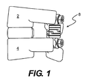
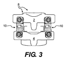
以下、図面を参照しつつ本発明を説明する。図1は、本発明の実施形態に係る、隣り合う椎骨2、4間に植え込まれた(implanted)機能的動的安定化システム8を示している。図2は、植え込まれた機能的動的安定化システムの上面図である。図3は、図1及び図2に示すシステム8の後面図である。図1〜図3に示すように、システム8は、脊椎の後部(posterior portion)に植え込まれて疾患のある椎骨2、4を安定化する1つ又は複数の弾性のある安定化ユニット10を備えている。
The present invention will be described below with reference to the drawings. FIG. 1 shows a functional
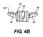
図4Aに示すように、各機能的動的安定化ユニット10は、茎ねじ(pedicle screw)または骨ねじ(bone screw)などといった少なくとも1つの骨アンカー50に連結された弾性のある連結具20を備えていてもよい。弾性のある連結具20は、スロット24及び開口部26を有する弾性のある本体部22を備えていてもよい。図4B及び図4Cに示すように、弾性のある本体部22は、その一端に骨アンカー50を挿入するための開口部32を有する保持アーム30(gripping arm)を備える一方、反対側の端部に骨アンカー50を受け入れるための開口部33を有する第2の保持アーム40を備えていてもよい。両保持アーム30、40は、本体部22と一体形成されていてもよく、また本体部22に取り外し可能に連結されていてもよい。例えば、図6に示すように、保持アーム40の一端は、例えば弾性のある本体部22のスリーブ90を介して、弾性のある本体部22に接続されるためのねじが形成されていてもよい。
As shown in FIG. 4A, each functional
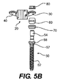
図5A、図5B及び図6に示すように、弾性のある連結具20の各保持アーム30、40は、その一方の側部に、半球状の(semi-spherical)ボールベアリング60に対して着座するように構成された凹状の空洞部34、44(concavely-shaped cavity)を備えていてもよい。ボールベアリング60は、骨アンカー50をはめる(fit)ことを可能にする貫通穴を備えていてもよい。ある実施形態では、骨アンカー50は、ねじが形成された細長い軸部52を有している。この軸部52は、ボールベアリング60が配置された頭部54(head portion)に連結されたフランジ56内に伸びていてもよい。さらに、フランジ56は、骨組織への固定(anchorage)を促進するとともに、長期間にわたるアンカー50の弛緩(loosening)を低減するための鋸歯状の縁部57(serration)を備えていてもよい。骨アンカー50は、例えば茎ねじであってもよい。骨アンカー50は、ユニット10又はシステム8を経皮的に配設することを可能にするために、カニューレで挿入することができるようになっているのが好ましい。凹状の空洞部34、44は、保持アーム30、40がボールベアリング60に対して摺動又は回転することを可能にし、これにより保持アーム30、40が骨アンカー50に対して相対的に移動することを可能にする。弾性のある本体部22を骨アンカー50に連結する一方、両者間の相対的な移動を可能するために、その他の適切な構造物(structures)を用いてもよい。
As shown in FIGS. 5A, 5B and 6, each holding
さらに図5A、図5B及び図10に示すように、フランジ56又はナット80に対向するようにしてねじ50にワッシャ70(washer)を配置してもよい。ワッシャ70は、ボールベアリング60に対向して位置するように形成及び構成されていてもよい。図4A及び図5Aに示すように、組み付けられた機能的動的安定化ユニット10は、さらに部品を互いに固定するために、ねじ50の頭部54にねじ留めされるナット80を備えている。
Furthermore, as shown in FIGS. 5A, 5B, and 10, a washer 70 (washer) may be disposed on the
各機能的動的安定化ユニット10は、1.5mmないし3.0mmの範囲の運動(motion)又は変位(displacement)を可能にするように構成されている。ここで、変位は、第1の保持アーム30に連結された第1の茎ねじの中心から、第2の保持アーム40に連結された第2の茎ねじの中心まで測定してもよい。この変位又は運動の範囲は、例えば回転、伸長又は平行移動により実現してもよい。
Each functional
図6は、図4A〜図4Cに示す弾性のある連結具の分解斜視図である。図6に示すように、いくつかの実施形態では、保持アーム40の1つは、弾性のある連結具20に取り外し可能に取り付けられている。ある実施形態では、弾性のある連結具20は、第2の保持アーム40及びその他の部品を連結具20に固定するためのねじが形成された開口部28を備えている。弾性のある連結具20内には、連結具の本体部22にねじ留めにより連結するために、その一端に開口部92を有するとともに開口部92の周囲にねじが形成されたリム94(rim)を有するスリーブ90が配置されていてもよい。スリーブ90は、連結具の本体部22内に配置されるとともに、ピン100(pin)を受け入れて該ピン100と協働するように構成されていてもよい。ピン100は、ねじが形成された端部を有する細長部102(elongate body)を備えていてもよい。この細長部102は、半球状の頭部領域104(head region)内に伸びるとともに、スカート部(skirt)又は肩部領域106(shoulder region)を備えていてもよい。スリーブ90とピン100とは相まって、連結具の本体部22内に伸長及び圧縮の係止部(stop)を形成し、患者の中立ゾーン又は活動ゾーンに対する弾性のある連結具20の移動範囲を制限する機能を有する。
FIG. 6 is an exploded perspective view of the elastic connector shown in FIGS. 4A to 4C. As shown in FIG. 6, in some embodiments, one of the retaining
スリーブ90のリム92には、取り外し可能な第2の保持アーム40のねじが形成された端部46と係合するためにねじが形成されていてもよい。連結具20の全体の長さは、スリーブ90内への第2の保持アーム40のねじ込み量を変えることにより(すなわち、スリーブ90内でアーム40を回転させる数を変えることにより)調整することができる。図6に示すように、取り外し可能な第2の保持アーム40のねじが形成された端部46は、複数の圧縮可能な指状突起43(finger projections)内に伸びている。各指状突起43は、フランジ付き縁部47(flanged lip)で終端している。フランジ付き縁部47は、ロック機構(locking mechanism)として機能し、第2の保持アーム40が組み付け後にスリーブ90へのねじ留めが弛む(unscrewed)のを防止する。図8Cに示すように、ねじが形成された端部46は、弾性プラグ110(elastomeric plug)を受け入れるための井戸部48(well)を備えていてもよい。弾性プラグ110は、例えばシリコーン、ポリエチレン又はポリエチルエーテルケトン(PEEK:polyethyletherketone)などといった柔軟で変形しやすい(compliant)プラスチック材料で形成することができる。取り外し可能な第2の保持アーム40がスリーブ90にねじ留めされているので、弾性プラグ110は、ねじが形成された開口部92と作用を及ぼし合い(interact)、保持アーム40とスリーブ90との間の弛み又は遊びを低減する。弾性のある本体部の長さを調整することができる一方、弾性のある本体部の圧縮量及び伸長量を制御することができるその他の適切な構造物を用いてもよい。例えば、保持アームを、摩擦係合(friction fit)もしくははめ込み連結(telescoping connection)で取り付け、あるいは歯止め機構(ratchet connection)を用いてもよい。
The
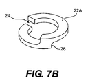
図7A及び図7Bに詳細に示すように、ある典型的な実施形態では、連結具の本体部22は、一連のコイルユニット22Aを備えた円筒体を備えている。一連のコイルユニット22は、互いに連結されたときに、段階的な(stepwise)一連のスロット24を形成し、これにより各スロット24は、弾性のある本体部22の開口部26で終端する(terminate)。いくつかの実施形態では、一連のコイルユニット22Aは、該コイルユニット22Aが互いに一体的に連結されるような態様で、単一片の材料で形成することができる。例えば、ある実施形態では、コイルユニット22Aは、管状の単一片の材料を切断し又は食刻する(etch)ことにより製作される。他の実施形態では、1つ又は複数のコイルユニット22Aは、個々に製作され互いに積層される。積層されたコイルユニット22Aは、例えば溶接により又は機械的な連結により互いに連結することができる。
As shown in detail in FIGS. 7A and 7B, in one exemplary embodiment, the
連結具の本体部22の剛性の度合いは、該連結具の本体部22を形成しているユニット22Aの数と、隣り合う2つのスロット24の角度、距離、幅又は高さに応じて変化するということが分かるであろう。また、1つ又は複数のユニット22Aは、本体部22の機械的な特性が変わるように、異なる材料で形成することができる。さらに、ユニット22A、スロット24及び開口部26の寸法は、単一の本体部22内で変えることができる。
The degree of rigidity of the
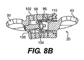
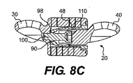
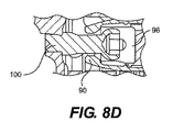
図8A〜図8Dは、安息状態(resting state)において完全に組み付けられた弾性のある連結具20(図8A及び図8D)、完全に伸長され又は乱れた(distracted)状態における弾性のある連結具20(図8B)、及び、完全に圧縮された状態にある弾性のある連結具20(図8C)の具体例を示している。図8Aに示す安息状態及び図8Dに示す伸長された状態においては、ピン100及びスリーブ90は、係合していない(すなわち、抵抗力又は運動制限要素(encumbrances)が存在しない)。完全に伸長され又は乱れた状態(図8B)においては、狭められた開口部98の幅よりも大きい寸法を有するピンの頭部104が、スリーブ90の狭められた開口部98に当接し、弾性のある本体部22が過度に伸長するのを防止する。完全に圧縮された状態(図8C)においては、図8Cに示すように、狭められた開口部98を伴ったスリーブ90の端部が第1の保持アーム30の内側縁部(inner edge)に当接する。連結具の本体部22の内側でスリーブ90とピン100とが協働して、移動可能な運動範囲を制御又は制限するための混乱(distraction)・圧縮停止機構を形成する。これにより、疾患のある椎骨分節だけでなく、機能的動的安定化システム自体についての損傷(injury)又は損壊(damage)を防止することができる。連結具の本体部22の運動範囲を制御又は制限するために、例えばはめ込み部材(telescoping element)又は内部ピストンなどといったその他の型式の協働要素を用いてもよい。
8A-8D show the
前記のとおり、機能的動的安定化ユニット10は、1対の椎骨分節を安定化するために単独で用いることができる。さらに、必要があれば、図9A及び図9Bに示すように、複数のユニット10を組み合わせて用い、複数の椎骨レベルの機能的動的安定化システム12を形成してもよい。複数の椎骨レベルの機能的動的安定化システム12は、互いに連結された2つ又はこれより多いユニット10を備えていてもよい。
As described above, the functional
図10は、図9A及び図9Bに示すシステムの側面図である。図10に示すように、システム12は、配列された1対の弾性のある連結具20を備えている。両連結具20は、各連結具20の第1の保持アーム30が、これらの組立体を互いに固定するナット80及び骨アンカー50を有し、1つのボールベアリング60の周囲に配置されている。2つより多い連結具20をこのように連結することが可能であり、どの1つの連結具についても第1の保持アーム30又は第2の保持アーム40のいずれかを、骨アンカー50の上の他の連結具20の第1の保持アーム30又は第2の保持アーム40のいずれかに組み合わせることが可能であるということが理解されるであろう。患者の脊椎の一方の側に沿って、又は両側に沿って任意の数の連結具20を植え込むことができる。さらに、ユニット10は、患者の病状(pathology)及び組織(anatomy)に応じて、異なる機械的特性のものを用いることができる。
FIG. 10 is a side view of the system shown in FIGS. 9A and 9B. As shown in FIG. 10, the
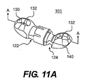
いくつかの実施形態では、本発明に係る安定化システムは、1つ又は複数の椎骨運動分節(vertebral motion segments)が、他の運動分節(motion segments)の機能的動的安定化と癒合(fusion)を行うことを可能にする。この目的を達するために、安定化システムは、図11Aにその1つが示されているように、剛性のある癒合促進連結具101(rigid fusion promoting coupler)を備えていてもよい。剛性のある連結具101は、前記の骨アンカー50、ボールベアリング60及びワッシャ70とともに用いることができるように構成してもよい。図11Aに示すように、剛性のある連結具101は、2つの部品122、124を備えている。各部品122、124は、それぞれ、前記の弾性のある連結具20の場合と同様の態様で、保持アーム130、140まで伸びている。各アーム130、140は、弾性のある連結具20に関して説明した態様と同様の態様で、骨アンカー50に取り付けるための開口部132を備えている。
In some embodiments, the stabilization system according to the present invention is such that one or more vertebral motion segments are combined with functional dynamic stabilization and fusion of other motion segments. ). To achieve this goal, the stabilization system may comprise a rigid
さらに、図11Bに示すように、2つの部品122、124は、互いに連結され、剛性のある連結具101の長さを調整することができるようになっている。例えば、部品122、124は、ねじが形成された表面を有し、剛性のある連結具101の長さは、弾性のある連結具20の長さを調整するための前記の手法と同様に、一方の部品122を他方の部品124に対してねじれさせることにより調整することができる。各保持アーム130、140は、それぞれその下側に、半球状のボールベアリング60に対して着座するように構成された凹状空洞部134、144を備えている。ここで、骨アンカー50に対する剛性のある連結具101の植え込み手法は、前記の弾性のある連結具20の場合と同様である。
Further, as shown in FIG. 11B, the two
図11Cに示すように、代替的な実施形態では、剛性のある癒合促進連結具201が設けられる。剛性のある癒合促進連結具201は、該連結具201の長さを調整するための部品のねじが形成された表面を利用しないことを除けば、剛性のある連結具101と同様である。剛性のある連結具201は、前記の骨アンカー50、ボールベアリング60及びワッシャ70とともに用いるように構成されている。図11Cに示すように、剛性のある連結具201は2つの部品222、224を備えている。そして、各部品222、224は、それぞれ、前記の弾性のある連結具20の場合と同様の態様で、保持アーム230、240まで伸びている。各保持アーム230、240は、弾性のある連結具20に関して説明した態様と同様の態様で、骨アンカー50に取り付けるための開口部(図示せず)を備えている。各保持アーム230、240は、それぞれその下側に、半球状のボールベアリング60に対して着座するように構成された凹状空洞部234、244を備えている。
As shown in FIG. 11C, in an alternative embodiment, a rigid
第1の部品222及び第2の部品224は、連結具201の長さの調整を促進するために互いに相対的に移動することができる。第1の部品222は、ねじが形成された表面に代えて、該第1の部品222を第2の部品224に対して相対的に固定するための固定部材230(fastening member)を受け入れるように構成された空洞部226(cavity)を備えていてもよい。第1及び第2の部品222、224はねじが形成された表面を備えていないので、両部品222、224は、これらをねじれさせるのではなく摺動させることにより互いに相対的に移動させることができる。このような実施形態では、外科医は、必要に応じて治療現場で、剛性のある連結具201の長さを調整することができる。
The
固定部材230は、ねじ又はナットなどといった適切な固定部材であればどのようなものであってもよい。例えば、固定部材230は、第1の部分と第2の部分とを有し、第1の部分が第1の部品222の位置を第2の部品224に対して相対的に固定するために第1の部品222の部分226と固定的に係合するように構成され、第2の部分が第1の部分を剛性のある連結具に締め付けるための挿入具と係合するように構成された脱離ナット(break-away nut)を備えていてもよい。脱離ナットの第2の部分は、低降伏力材料(lower yield-strength material)からなる領域又は薄い壁を有し、十分なトルクが加えられたときに(すなわち、ナット230が十分に締め付けられたとき)破損するように構成された脱離部(break-away portion)であってもよい。空洞部226の内表面と固定部材230の外表面とには、空洞部226と固定部材230の係合を促進するためのねじが設けられている。
The fixing
前記のとおり、安定化システムは弾性のある機能的動的連結具20及び剛性のある機能的動的連結具101の両方を有し、これによりモジュール式のシステムが、患者の脊椎の個々の分節における癒合(fusion)と移動の予防(preservation)の組合せを可能にする。システムにおける剛性のある連結具101と弾性のある連結具20との互換性(interchangeability)を確保することにより、外科医は、患者の特別な要請に対処する(address)ためのより大きな融通性(flexibility)を有するであろう。それゆえ、1つの椎骨分節(spinal segment)は、機能的動的安定性(すなわち、非癒合性)を有する一方、隣り合う分節は剛性のある分節固定性(すなわち、癒合性)を有する。
As described above, the stabilization system has both an elastic functional
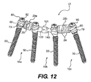
図12は、弾性のある連結具20a、20bと剛性のある連結具101とを用いた3つの個別の安定化ユニット10a、10b、10cを備えている多分節システム12(multi-segmental system)を示している。ユニット10a、10cの弾性のある連結具20a、20bは、疾患のある運動分節の分節剛性を増加させるとともに、湾曲、伸長、横曲げ及び回転における運動範囲を制限する一方、運動を予防する(preserve)。適切な寸法の連結具20a、20bを選択することにより、分節後部の高さ(posterior segmental height)を首尾良く調整することができる。さらに、ユニット10bの癒合を促進する剛性のある連結具101は、剛性のある分節の固定を実現し、これにより癒合を促進する一方、同一の型式の骨アンカー50及び器具(instrument)を用いることを可能にする。
FIG. 12 shows a
モジュール式のシステム12には多くの利点がある。第1に、前記のとおり、植え込まれたシステムは、骨アンカー50により椎骨に連結された弾性のある機能的動的連結具20のみを備えるだけでよい。しかしながら、その後に、疾患の進行、持続する痛み、その他の症状又は患者の症状のその他の変化に応じて、1つ又は複数の予め治療された椎骨レベルを癒合させる(fuse)のが望ましい。それゆえ、その後の外科処置においては、外科医は、同一の骨アンカーを使用しつつ、それ以前に植え込まれた弾性のある連結具を、単純に剛性のある連結具101と取り換えることができる。
The
前記のとおり、本発明に係るユニット及びシステムは、最小限の侵襲性(minimally-invasive)と筋肉温存性(muscle-sparing)とを実現しつつ植え込むことができる。このような手法は、組織の損傷を最小限にする一連の切開部(incisions)又は経皮的方法を用いている。 As described above, the unit and system according to the present invention can be implanted while achieving minimally-invasive and muscle-sparing. Such techniques use a series of incisions or percutaneous methods that minimize tissue damage.
図13〜図19は、典型的な実施形態に係る、個別に設けられ又はシステムを構成する集合として設けられる挿入器具(insertion instrument)を示している。本発明に係るシステムの典型的な使用方法においては、患者の脊椎の茎(pedicle)内に、一連のKワイヤ(キルシュナー鋼線)200が挿入される。Kワイヤ200は、患者の背中の一連の小さい切開部を経由して挿入される。さらに、図13に示すように、外科医によるKワイヤ200及び切開部の配置を助けるためにワイヤ型板202(wire template)を設けてもよい。図13に示すように、ワイヤ型板202は、患者の脊椎の茎に沿って配列された予め設けられた開口部204を備えていてもよい。開口部204は、治療すべき椎骨の両茎と一列となるように左右相称に(bilaterally)配置してもよい。型板は、茎の間隔(pedicle spacing)にばらつき(variation)がある患者に順応させるために種々の寸法に形成してもよい。
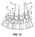
FIGS. 13-19 illustrate an insertion instrument that is provided separately or as a collection that constitutes a system, according to an exemplary embodiment. In a typical use of the system according to the invention, a series of K-wires (Kirschner steel wires) 200 are inserted into the pedicle of the patient's spine. K-
Kワイヤ200の挿入の後、カニューレに挿入された骨アンカー50をKワイヤ200に外挿し、そして図14Aに示すような一連の延長ロッド220a、220b、220c(extension rod)を用いて、骨アンカーを選択された椎骨内に植え込むことができる。図14Bに示すように、延長ロッドを骨アンカー50の頭部54に取り付け、骨アンカー50の操作を可能にする。さらに、図示していない拡張スリーブ(dilatation sleeve)を設け、延長ロッドを、拡張スリーブを通り抜けさせて、植え込み部位(implantation site)に接近させる(access)ことができる。骨アンカー50の植え込み時又は植え込みの後に、延長ロッド220を骨アンカー50と取り付けられた椎骨とを操作するのに用いて、負荷がかかるとともに静止した状態で十分な移動範囲を確実に確保する(ascertain)ことができる。このような情報は、外科医が、この椎骨分節(spine segment)にとって望ましい矯正移動(corrective motion)の可能範囲を予測するのに役立つであろう。
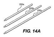
After insertion of the K-
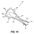
図15に示すように、測径器240(caliper)には、機器の組物(instrument set)が設けられていてもよい。測計器240は、1対の旋回アーム242、244(pivoting arm)を備えている。各旋回アームは、それぞれ指係合穴246、248(finger engaging opening)まで伸び、それぞれ反対側の端部で保持端250、252に終端している(terminate)。旋回アーム242、244は、板ばね254(leaf spring)を介して互いに連結されている。図15に示すように、旋回アーム242、244の端部は、背板256上の指標マーク258を用いて、隣り合う1対の骨アンカー50間の距離を読みとり又は測定することができるように構成されている。保持端250、252は、各骨アンカー50のボールベアリング60の一部分を保持するように構成してもよい。これにより、骨アンカー50が互いに平行でないとき又は特定の角度(unique angle)で配置されているときでも、測計器240はその機能を発揮することができる。
As shown in FIG. 15, the diameter measuring device 240 (caliper) may be provided with an instrument set. The
図16は、ボールベアリング60、ワッシャ70又はナット80などといった骨アンカーの他の部品に連結されるように構成された種々の延長ロッド260(rod extension)を示している。各延長ロッド260は、各部品を最小限の侵襲性で又は経皮的に操作することを可能にする。
FIG. 16 shows
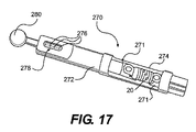
骨アンカー50が所定の位置に配置され、隣り合う1対の骨アンカー50間の距離が決定された後、外科医は、骨アンカー50間に配置するための適切な寸法をもつ弾性のある機能的動的連結具20又は剛性のある癒合促進連結具101を選択することができる。図17に示すものと同様の連結具の長さ調整器270を設け、連結具の長さがその挿入の前に矯正されることを確実にしてもよい。図17に示すように、長さ調整器270は、その間に連結具20、101を保持することができる1対の握り部271(grip)を有する本体部272(body)を備えていてもよい。1対の握り部271は、連結具のための挿入領域274を形成する。本体部272内に、1つの握り部271に対して付勢力(biased force)を作用させるばね負荷機構(spring-loaded mechanism)が設けられている。ばね負荷機構は、ノブ280(knob)を回転させることにより制御することができ、これにより連結具20、101をねじれさせ、その結果その長さを調整することができる。さらに、本体部272は窓部278(window)を備えていてもよい。この窓部内には、連結具の長さを示す指標276(indicia)が表示される。図17では弾性のある連結具20が記載されているが、長さ調整器270は剛性のある連結具10にも用いることができるということが理解される。
After the
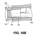
次に、適切に寸法が設定された連結具20、101が、Kワイヤに沿って下向きに、骨アンカー50のボールベアリング60の上まで摺動させられる。この後、連結具20、101を所定の位置に配置するためにナット80を用いてもよい。いくつかの実施形態では、ナット80は、過大な又は過小な締め付けを防止するといった特性を有していてもよい。例えば、図18Aは、典型的な実施形態に係る、骨アンカーと係合している下部186を上部184に連結する、脱離部182(break-away portion)を有する適切なナット180を示している。低降伏力材料からなる領域又は薄壁を有している脱離部182は、十分なトルクがかけられたとき(すなわち、ナット80が十分に締め付けられたとき)には破損するように構成されている。
Next, appropriately dimensioned
ナット180は、骨アンカー50及び連結具20、101を植え込むために用いられる侵襲性が最小限である手法(minimally-invasive approach)により挿入することができる。例えば、図19は、ナット180の挿入に有用な典型的な挿入具290を示している。この挿入具290は、ハンドル部294から、反対側の端部に位置するナット連結端296まで伸びている細長部材292を備えている。ナット連結端296は、図18Bに示すように、上部184でナットに堅固に取り付けられるように構成されている。そして、ナットが連結された細長部材292は、前記の接近部位(access site)に挿入して、ナット180を骨アンカー50に固定することができるように構成されている。十分な締め付けでもって、脱離部184でナット180を破損させ、骨アンカーに下部186を残留させつつ、上部184を離脱させることを可能にする。
The
外科医は、患者の脊椎におけるすべての疾患のある椎骨レベルを治療するまで、隣り合う椎骨レベルで上記処置を繰り返すことができる。すべての処置は、経皮的に、及び/又は、周囲の組織への傷害(disruption)を最小限にしつつ実施することができる。 The surgeon can repeat the procedure at adjacent vertebral levels until he has treated all diseased vertebral levels in the patient's spine. All procedures can be performed percutaneously and / or with minimal disruption to surrounding tissue.
当業者であれば、本明細書の記載と本明細書に開示された発明の実用的意義とを考察することにより、本発明には他の種々の実施形態がありうることが分かるであろう。本明細書及びこれに記載された実施形態は単なる例示に過ぎず、本発明の技術範囲及び技術思想は、特許請求の範囲によって解釈されるべきである。 Those skilled in the art will recognize that the present invention may have various other embodiments by considering the description herein and the practical significance of the invention disclosed herein. . The present specification and the embodiments described therein are merely examples, and the technical scope and spirit of the present invention should be construed by the claims.
2 椎骨、4 椎骨、8 機能的動的安定化システム、10 弾性のある安定化ユニット、20 連結具、30 保持アーム、40 保持アーム、50 骨アンカー、60 ボールベアリング、70 ワッシャ、80 ナット、90 スリーブ。 2 vertebrae, 4 vertebrae, 8 functional dynamic stabilization system, 10 elastic stabilization unit, 20 coupler, 30 retention arm, 40 retention arm, 50 bone anchor, 60 ball bearing, 70 washer, 80 nut, 90 sleeve.
Claims (56)
上記弾性のある連結具の1対のアームと協働して該連結具を骨に取り付けるように構成されている複数の骨アンカーを有する骨固定システムとを備えていることを特徴とする脊椎安定化ユニット。 An elastic coupling device having a main body and a pair of arms, wherein the pair of arms are arranged at opposite ends of the coupling device, and the movement range limiting mechanism is bent and deformed by the coupling device. A connector configured to control the amount, the amount of compression, and the amount of expansion;
A spinal stabilization system comprising a bone anchoring system having a plurality of bone anchors configured to cooperate with a pair of arms of the resilient connector to attach the connector to bone. Unit.
上記連結具の第1端部から上記連結具の第2端部に向かって連結具内部を伸びるとともに、狭められた遠位開口部を有するスリーブと、
上記連結具の上記第2端部から上記連結具の上記第1端部に向かって連結具内部を伸びるとともに、上記スリーブ内に配置され拡大された端部を有する細長部とを備えていて、
上記細長部の寸法が、上記連結具が伸長され又は曲げられたときには上記の拡大された端部が上記の狭められた遠位開口部の壁に隣接し、上記連結具が圧縮されたときには上記スリーブが上記連結部の上記第2端部に隣接するように設定されていることを特徴とする、請求項1に記載のユニット。 The movement range limiting mechanism is
A sleeve extending from the first end of the connector toward the second end of the connector and having a narrowed distal opening;
The inside of the connector extends from the second end of the connector toward the first end of the connector, and has an elongated portion disposed in the sleeve and having an enlarged end,
The elongated portion is sized such that when the connector is extended or bent, the enlarged end is adjacent to the wall of the narrowed distal opening and when the connector is compressed, The unit according to claim 1, wherein a sleeve is set so as to be adjacent to the second end portion of the connecting portion.
第1要素と、
上記第1要素内に移動可能に配置されるとともに、上記第1要素と協働する第2要素とを有し、
上記第2要素に対する上記第1要素の第1方向の移動が、上記連結具の伸長する範囲を決定し、上記第2要素に対する上記第1要素の、上記第1方向とは反対向きの第2方向の移動が、上記連結具の圧縮する範囲を決定することを特徴とする、請求項1に記載のユニット。 The movement range limiting mechanism is
A first element;
A second element movably disposed within the first element and cooperating with the first element;
The movement of the first element in the first direction relative to the second element determines the extent to which the coupler extends, and the second element of the first element relative to the second element is in a second direction opposite to the first direction. 2. A unit as claimed in claim 1, characterized in that the movement in direction determines the extent to which the coupling is compressed.
上記骨固定システムが、さらに各骨アンカーのための半球状のボールベアリングを備えていることを特徴とする、請求項5に記載のユニット。 Each arm has a recess with an opening,
The unit according to claim 5, characterized in that the bone anchoring system further comprises a hemispherical ball bearing for each bone anchor.
各ナットは、該ナットに十分なトルクが作用したときに破損するように構成された狭められた脱離部を有していることを特徴とする、請求項1に記載のユニット。 The bone fixation system further comprises a plurality of nuts,
The unit according to claim 1, wherein each nut has a narrowed detachment configured to break when a sufficient torque is applied to the nut.
1対のアームを有する剛性のある連結具であって、上記アームが該剛性のある連結具の互いに対向する端部に配置されている連結具と、
上記弾性のある連結具のアーム及び上記剛性のある連結具のアームと協働して該連結具を骨に取り付けるように構成されている複数の骨アンカーを有する骨固定システムとを備えていることを特徴とするモジュール式の脊椎安定化システム。 An elastic coupling device having a pair of arms, wherein the arms are arranged on opposite ends of the elastic coupling device, and a range-of-motion limiting mechanism is a bending deformation amount of the elastic coupling device. And a connector configured to control the amount of compression and the amount of expansion;
A rigid connector having a pair of arms, wherein the arms are disposed at opposite ends of the rigid connector;
A bone fixation system having a plurality of bone anchors configured to cooperate with the resilient coupling arm and the rigid coupling arm to attach the coupling to the bone. A modular spinal stabilization system.
上記円筒体の壁に、1つ又は複数の細長い穴が形成されていることを特徴とする、請求項17に記載のシステム。 The elastic connector has a cylindrical body,
The system of claim 17, wherein one or more elongated holes are formed in the wall of the cylindrical body.
第1要素と、
上記第1要素内に移動可能に配置されるとともに、上記第1要素と協働する第2要素とを有し、
上記第2要素に対する上記第1要素の第1方向の移動が、上記弾性のある連結具の伸長する範囲を決定し、上記第2要素に対する上記第1要素の、上記第1方向とは反対向きの第2方向の移動が、上記弾性のある連結具の圧縮する範囲を決定することを特徴とする、請求項17に記載のシステム。 The movement range limiting mechanism is
A first element;
A second element movably disposed within the first element and cooperating with the first element;
Movement of the first element in the first direction relative to the second element determines the extent of extension of the elastic coupling, and the first element relative to the second element is opposite to the first direction. 18. A system according to claim 17, characterized in that the movement in the second direction determines the extent to which the elastic coupling is compressed.
上記弾性のある連結具の第1端部から上記弾性のある連結具の第2端部に向かって連結具内部を伸びるとともに、狭められた遠位開口部を有するスリーブと、
上記弾性のある連結具の上記第2端部から上記弾性のある連結具の上記第1端部に向かって連結具内部を伸びるとともに、上記スリーブ内に配置され拡大された端部を有する細長部とを備えていて、
上記細長部の寸法が、上記弾性のある連結具が伸長され又は曲げられたときには上記の拡大された端部が上記の狭められた遠位開口部の壁に隣接し、上記弾性のある連結具が圧縮されたときには上記スリーブが上記弾性のある連結部の上記第2端部に隣接するように設定されていることを特徴とする、請求項17に記載のシステム。 The movement range limiting mechanism is
A sleeve extending from the first end of the elastic connector toward the second end of the elastic connector and having a narrowed distal opening;
An elongated portion extending from the second end of the elastic connector toward the first end of the elastic connector toward the first end and having an enlarged end disposed within the sleeve With
The elongated connector is such that when the elastic connector is extended or bent, the enlarged end is adjacent to the wall of the narrowed distal opening, and the elastic connector 18. The system of claim 17, wherein the sleeve is set adjacent to the second end of the resilient coupling when the is compressed.
上記弾性のある連結具の上記アーム及び上記剛性のある連結具のアームが、それぞれ、半球状のボールベアリングと係合するように構成された開口部を有する凹部を備えていることを特徴とする、請求項17に記載のシステム。 The bone fixation system further comprises a plurality of hemispherical ball bearings;
The arm of the elastic connector and the arm of the rigid connector each include a recess having an opening configured to engage with a hemispherical ball bearing. The system of claim 17.
各ナットは、該ナットに十分なトルクが作用したときに破損するように構成された狭められた脱離部を有していることを特徴とする、請求項17に記載のシステム。 The bone fixation system further comprises a plurality of nuts for fixing the rigid connector or the elastic connector to each bone anchor;
18. A system according to claim 17, wherein each nut has a narrowed detachment configured to break when sufficient torque is applied to the nut.
第2の骨アンカーを、上記第1の椎骨と隣り合う第2の椎骨に取り付ける過程と、
本体部と、1対のアームと、連結具曲げ変形量と連結具圧縮量と連結具伸長量とを制御するように構成された運動範囲制限機構とを有する弾性のある連結具の第1及び第2のアームを、それぞれ、上記第1及び第2の骨アンカーに連結する過程とを有することを特徴とする脊椎を治療する方法。 Attaching the first bone anchor to the first vertebra;
Attaching a second bone anchor to a second vertebra adjacent to the first vertebra;
A first and a resilient coupler having a body portion, a pair of arms, and a movement range limiting mechanism configured to control the amount of bending deformation of the coupler, the amount of compression of the coupler, and the amount of extension of the coupler. Connecting a second arm to the first and second bone anchors, respectively, for treating the spine.
剛性のある連結具を、上記第1のアンカー及び上記第2のアンカーのうちの一方のアンカーと上記第3の骨アンカーとに取り付ける過程とを有していて、
上記剛性のある連結具が、2つの椎骨間の移動を防止するように構成されていることを特徴とする、請求項38に記載の方法。 And a process of attaching a third bone anchor to the third vertebra,
Attaching a rigid connector to one of the first anchor and the second anchor and to the third bone anchor;
40. The method of claim 38, wherein the rigid connector is configured to prevent movement between two vertebrae.
上記弾性のある連結具を剛性のある連結具と取り換える過程とを有することを特徴とする、請求項38に記載の方法。 And removing the elastic connector from the first and second bone anchors attached to the first and second vertebrae;
39. The method of claim 38, including the step of replacing the resilient connector with a rigid connector.
上記曲げ変形量及び伸長量を制御する過程で、上記弾性のある連結具の第1端部から上記弾性のある連結具の第2端部に向かって連結具内を伸長し、狭められた遠位開口部を有するスリーブを設けるとともに、
拡大された遠位端を有し上記第2の弾性のある連結具から伸長する細長い本体を、上記弾性のある連結具が伸長され又は曲げられたときに上記拡大された遠位端が上記狭められた開口部の壁に隣接するように配置することを特徴とする、請求項46に記載の方法。 Furthermore, it has a process of controlling the amount of bending deformation and extension of the elastic connector,
In the process of controlling the amount of bending deformation and the amount of extension, the distance between the first end of the elastic connector and the second end of the elastic connector is extended and narrowed. Providing a sleeve having a lateral opening;
An elongated body having an enlarged distal end and extending from the second elastic connector narrows the elongated body when the elastic connector is extended or bent. 47. The method of claim 46, wherein the method is disposed adjacent to a wall of the formed opening.
上記圧縮量を制御する過程で、上記弾性のある連結具の第1端部から上記弾性のある連結具の第2端部に向かって連結具内を伸長し、狭められた遠位開口部を有するスリーブを設けるとともに、
拡大された遠位端を有し上記第2の弾性のある連結具から伸長する細長い本体を、上記弾性のある連結具が圧縮されたときに上記スリーブが上記弾性のある連結具の第2の端部に隣接するように配置することを特徴とする、請求項46に記載の方法。 Furthermore, it has a process of controlling the amount of compression of the elastic connector,
In the process of controlling the amount of compression, the inner end of the connector is extended from the first end of the elastic connector toward the second end of the elastic connector. Providing a sleeve having,
An elongated body having an enlarged distal end and extending from the second resilient connector, the sleeve being a second of the resilient connector when the resilient connector is compressed. The method according to claim 46, wherein the method is arranged adjacent to the end.
治療すべき少なくとも2つの隣り合う椎骨に、少なくとも1つの切開部を生成する過程と、
少なくとも2つのワイヤを、各ワイヤが上記少なくとも2つの椎骨のうちの1つの茎に個別に当接するように配置する過程と、
治療すべき第1及び第2の隣り合う椎骨にねじを締結する過程と、
弾性のある連結具を、上記第1及び第2の隣り合う椎骨の上記2つのねじに取り付ける過程とを有することを特徴とする方法。 A method of implanting a spinal stabilization unit,
Creating at least one incision in at least two adjacent vertebrae to be treated;
Placing at least two wires such that each wire individually abuts a stem of one of the at least two vertebrae;
Fastening a screw to the first and second adjacent vertebrae to be treated;
Attaching a resilient connector to the two screws of the first and second adjacent vertebrae.
少なくとも1つのワイヤを、上記第3の椎骨の茎に個別に当接するように配置する過程と、
治療すべき第3の椎骨にねじを締結する過程と、
剛性のある連結具を、上記第3のねじと、上記第1及び第2のねじのうちの1つのねじとに取り付ける過程とを有することを特徴とする、請求項49に記載の方法。 Further, generating at least one incision in the third vertebra to be treated;
Placing at least one wire in separate contact with the third vertebral stem;
Fastening a screw to the third vertebra to be treated;
50. The method of claim 49, comprising attaching a rigid connector to the third screw and one of the first and second screws.
Applications Claiming Priority (3)
| Application Number | Priority Date | Filing Date | Title |
|---|---|---|---|
| US86934206P | 2006-12-10 | 2006-12-10 | |
| US91436007P | 2007-04-27 | 2007-04-27 | |
| PCT/US2007/086800 WO2008073830A1 (en) | 2006-12-10 | 2007-12-07 | Posterior functionally dynamic stabilization system |
Publications (2)
| Publication Number | Publication Date |
|---|---|
| JP2010512228A true JP2010512228A (en) | 2010-04-22 |
| JP2010512228A5 JP2010512228A5 (en) | 2011-02-03 |
Family
ID=39323009
Family Applications (1)
| Application Number | Title | Priority Date | Filing Date |
|---|---|---|---|
| JP2009541493A Pending JP2010512228A (en) | 2006-12-10 | 2007-12-07 | Rear functional dynamic stabilization system |
Country Status (14)
| Country | Link |
|---|---|
| US (3) | US8920473B2 (en) |
| EP (2) | EP2120748B1 (en) |
| JP (1) | JP2010512228A (en) |
| KR (1) | KR20090097909A (en) |
| CN (1) | CN102525623B (en) |
| AR (1) | AR064204A1 (en) |
| AU (1) | AU2007333199B2 (en) |
| CA (1) | CA2671868A1 (en) |
| ES (1) | ES2601355T3 (en) |
| HK (3) | HK1138168A1 (en) |
| IL (1) | IL198962A0 (en) |
| MX (1) | MX2009005843A (en) |
| TW (1) | TW200843691A (en) |
| WO (1) | WO2008073830A1 (en) |
Families Citing this family (73)
| Publication number | Priority date | Publication date | Assignee | Title |
|---|---|---|---|---|
| US10729469B2 (en) | 2006-01-09 | 2020-08-04 | Roger P. Jackson | Flexible spinal stabilization assembly with spacer having off-axis core member |
| US20160242816A9 (en) | 2001-05-09 | 2016-08-25 | Roger P. Jackson | Dynamic spinal stabilization assembly with elastic bumpers and locking limited travel closure mechanisms |
| US7862587B2 (en) | 2004-02-27 | 2011-01-04 | Jackson Roger P | Dynamic stabilization assemblies, tool set and method |
| US10258382B2 (en) | 2007-01-18 | 2019-04-16 | Roger P. Jackson | Rod-cord dynamic connection assemblies with slidable bone anchor attachment members along the cord |
| DE10320417A1 (en) * | 2003-05-07 | 2004-12-02 | Biedermann Motech Gmbh | Dynamic anchoring device and dynamic stabilization device for bones, in particular for vertebrae, with such an anchoring device |
| US9492203B2 (en) * | 2004-02-17 | 2016-11-15 | Globus Medical, Inc. | Facet joint replacement instruments and methods |
| US11241261B2 (en) | 2005-09-30 | 2022-02-08 | Roger P Jackson | Apparatus and method for soft spinal stabilization using a tensionable cord and releasable end structure |
| US8523904B2 (en) | 2004-03-09 | 2013-09-03 | The Board Of Trustees Of The Leland Stanford Junior University | Methods and systems for constraint of spinous processes with attachment |
| US7458981B2 (en) | 2004-03-09 | 2008-12-02 | The Board Of Trustees Of The Leland Stanford Junior University | Spinal implant and method for restricting spinal flexion |
| US9216041B2 (en) * | 2009-06-15 | 2015-12-22 | Roger P. Jackson | Spinal connecting members with tensioned cords and rigid sleeves for engaging compression inserts |
| US7901437B2 (en) | 2007-01-26 | 2011-03-08 | Jackson Roger P | Dynamic stabilization member with molded connection |
| US8187307B2 (en) | 2006-10-19 | 2012-05-29 | Simpirica Spine, Inc. | Structures and methods for constraining spinal processes with single connector |
| US8029541B2 (en) | 2006-10-19 | 2011-10-04 | Simpirica Spine, Inc. | Methods and systems for laterally stabilized constraint of spinous processes |
| US8162982B2 (en) | 2006-10-19 | 2012-04-24 | Simpirica Spine, Inc. | Methods and systems for constraint of multiple spine segments |
| US9867640B2 (en) | 2006-12-07 | 2018-01-16 | Nexus Spine, LLC | Press-on pedicle screw assembly |
| US8366745B2 (en) | 2007-05-01 | 2013-02-05 | Jackson Roger P | Dynamic stabilization assembly having pre-compressed spacers with differential displacements |
| US11224463B2 (en) | 2007-01-18 | 2022-01-18 | Roger P. Jackson | Dynamic stabilization connecting member with pre-tensioned flexible core member |
| US8475498B2 (en) | 2007-01-18 | 2013-07-02 | Roger P. Jackson | Dynamic stabilization connecting member with cord connection |
| US10383660B2 (en) | 2007-05-01 | 2019-08-20 | Roger P. Jackson | Soft stabilization assemblies with pretensioned cords |
| US8021396B2 (en) | 2007-06-05 | 2011-09-20 | Spartek Medical, Inc. | Configurable dynamic spinal rod and method for dynamic stabilization of the spine |
| US8092501B2 (en) | 2007-06-05 | 2012-01-10 | Spartek Medical, Inc. | Dynamic spinal rod and method for dynamic stabilization of the spine |
| US8114134B2 (en) | 2007-06-05 | 2012-02-14 | Spartek Medical, Inc. | Spinal prosthesis having a three bar linkage for motion preservation and dynamic stabilization of the spine |
| US8105356B2 (en) | 2007-06-05 | 2012-01-31 | Spartek Medical, Inc. | Bone anchor with a curved mounting element for a dynamic stabilization and motion preservation spinal implantation system and method |
| WO2008151091A1 (en) | 2007-06-05 | 2008-12-11 | Spartek Medical, Inc. | A deflection rod system for a dynamic stabilization and motion preservation spinal implantation system and method |
| US8048115B2 (en) | 2007-06-05 | 2011-11-01 | Spartek Medical, Inc. | Surgical tool and method for implantation of a dynamic bone anchor |
| US8083772B2 (en) | 2007-06-05 | 2011-12-27 | Spartek Medical, Inc. | Dynamic spinal rod assembly and method for dynamic stabilization of the spine |
| US20100036424A1 (en) * | 2007-06-22 | 2010-02-11 | Simpirica Spine, Inc. | Methods and systems for increasing the bending stiffness and constraining the spreading of a spinal segment |
| US8403961B2 (en) | 2007-06-22 | 2013-03-26 | Simpirica Spine, Inc. | Methods and devices for controlled flexion restriction of spinal segments |
| US20110172708A1 (en) * | 2007-06-22 | 2011-07-14 | Simpirica Spine, Inc. | Methods and systems for increasing the bending stiffness of a spinal segment with elongation limit |
| ES2374577T3 (en) * | 2007-10-11 | 2012-02-20 | Biedermann Motech Gmbh | MODULAR VARILLA SYSTEM FOR THE STABILIZATION OF THE VERTEBRAL COLUMN. |
| US8894687B2 (en) | 2011-04-25 | 2014-11-25 | Nexus Spine, L.L.C. | Coupling system for surgical construct |
| US8083775B2 (en) | 2008-02-26 | 2011-12-27 | Spartek Medical, Inc. | Load-sharing bone anchor having a natural center of rotation and method for dynamic stabilization of the spine |
| US20100030224A1 (en) | 2008-02-26 | 2010-02-04 | Spartek Medical, Inc. | Surgical tool and method for connecting a dynamic bone anchor and dynamic vertical rod |
| US8097024B2 (en) | 2008-02-26 | 2012-01-17 | Spartek Medical, Inc. | Load-sharing bone anchor having a deflectable post and method for stabilization of the spine |
| US8337536B2 (en) | 2008-02-26 | 2012-12-25 | Spartek Medical, Inc. | Load-sharing bone anchor having a deflectable post with a compliant ring and method for stabilization of the spine |
| US8057517B2 (en) | 2008-02-26 | 2011-11-15 | Spartek Medical, Inc. | Load-sharing component having a deflectable post and centering spring and method for dynamic stabilization of the spine |
| US8048125B2 (en) | 2008-02-26 | 2011-11-01 | Spartek Medical, Inc. | Versatile offset polyaxial connector and method for dynamic stabilization of the spine |
| US8333792B2 (en) | 2008-02-26 | 2012-12-18 | Spartek Medical, Inc. | Load-sharing bone anchor having a deflectable post and method for dynamic stabilization of the spine |
| US8267979B2 (en) | 2008-02-26 | 2012-09-18 | Spartek Medical, Inc. | Load-sharing bone anchor having a deflectable post and axial spring and method for dynamic stabilization of the spine |
| US8211155B2 (en) | 2008-02-26 | 2012-07-03 | Spartek Medical, Inc. | Load-sharing bone anchor having a durable compliant member and method for dynamic stabilization of the spine |
| WO2009149399A1 (en) * | 2008-06-06 | 2009-12-10 | Simpirica Spine, Inc. | Methods and apparatus for deploying spinous process constraints |
| US8308771B2 (en) | 2008-06-06 | 2012-11-13 | Simpirica Spine, Inc. | Methods and apparatus for locking a band |
| JP2012529969A (en) | 2008-08-01 | 2012-11-29 | ロジャー・ピー・ジャクソン | Longitudinal connecting member with tensioning cord with sleeve |
| CA2743721A1 (en) | 2009-02-19 | 2010-08-26 | Anton E. Bowden | Compliant dynamic spinal implant |
| WO2010096829A2 (en) * | 2009-02-23 | 2010-08-26 | Crocker Spinal, L.L.C. | Press-on link for surgical screws |
| US8529606B2 (en) | 2009-03-10 | 2013-09-10 | Simpirica Spine, Inc. | Surgical tether apparatus and methods of use |
| WO2010104975A1 (en) * | 2009-03-10 | 2010-09-16 | Simpirica Spine, Inc. | Surgical tether apparatus and methods of use |
| JP5681122B2 (en) | 2009-03-10 | 2015-03-04 | シンピライカ スパイン, インコーポレイテッド | Surgical tether device and method of use |
| WO2010108010A2 (en) | 2009-03-19 | 2010-09-23 | Halverson Peter A | Spinal implant |
| US8668719B2 (en) * | 2009-03-30 | 2014-03-11 | Simpirica Spine, Inc. | Methods and apparatus for improving shear loading capacity of a spinal segment |
| US8292927B2 (en) * | 2009-04-24 | 2012-10-23 | Warsaw Orthopedic, Inc. | Flexible articulating spinal rod |
| US8105360B1 (en) | 2009-07-16 | 2012-01-31 | Orthonex LLC | Device for dynamic stabilization of the spine |
| US9157497B1 (en) | 2009-10-30 | 2015-10-13 | Brigham Young University | Lamina emergent torsional joint and related methods |
| EP2506785A4 (en) | 2009-12-02 | 2014-10-15 | Spartek Medical Inc | Low profile spinal prosthesis incorporating a bone anchor having a deflectable post and a compound spinal rod |
| DE102010000339A1 (en) | 2010-02-08 | 2011-08-11 | Aesculap AG, 78532 | Connecting element for a spine stabilization system and spine stabilization system |
| US8518085B2 (en) | 2010-06-10 | 2013-08-27 | Spartek Medical, Inc. | Adaptive spinal rod and methods for stabilization of the spine |
| JP2013540468A (en) | 2010-09-08 | 2013-11-07 | ロジャー・ピー・ジャクソン | Dynamic fixing member having an elastic part and an inelastic part |
| DE102010060101A1 (en) | 2010-09-20 | 2012-03-22 | Aesculap Ag | Spinal stabilization system and surgical device for temporarily stiffening a flexible intermediate portion of a spinal stabilization system connector |
| US8721566B2 (en) | 2010-11-12 | 2014-05-13 | Robert A. Connor | Spinal motion measurement device |
| US9095332B2 (en) | 2011-02-09 | 2015-08-04 | Redyns Medical Llc | Method and apparatus for attaching an elongated object to bone |
| EP2717807A2 (en) * | 2011-06-07 | 2014-04-16 | Brigham Young University | Serpentine spinal stability device and associated methods |
| US8430916B1 (en) | 2012-02-07 | 2013-04-30 | Spartek Medical, Inc. | Spinal rod connectors, methods of use, and spinal prosthesis incorporating spinal rod connectors |
| DE102012202750A1 (en) | 2012-02-22 | 2013-08-22 | Aces Gmbh | Dynamic stabilization device for treating degenerative diseases of spinal column, has support- and mating surfaces formed for clamping by load of spring element, and retaining elements movably mounted against each other in direction |
| US9402673B2 (en) | 2012-09-28 | 2016-08-02 | DePuy Synthes Products, Inc. | Devices and methods for breaking and retaining surgical reduction tabs |
| DE102013110173A1 (en) | 2013-09-16 | 2015-03-19 | Aesculap Ag | Connecting element and spine stabilization system |
| US10603091B2 (en) | 2014-02-24 | 2020-03-31 | Curtin University Of Technology | Fastener |
| FR3018678B1 (en) * | 2014-03-20 | 2016-03-11 | Spineway | SURGICAL ASSEMBLY, BONE ANCHORING SCREW AND DEVICE FOR EXTENSION OF SUCH SCREWS FORMING PART OF SAID SURGICAL ASSEMBLY |
| US9642651B2 (en) | 2014-06-12 | 2017-05-09 | Brigham Young University | Inverted serpentine spinal stability device and associated methods |
| JP2018532492A (en) * | 2015-10-13 | 2018-11-08 | プロビデンス メディカル テクノロジー インコーポレイテッド | Spinal joint implant delivery apparatus and system |
| CN108778152B (en) | 2016-03-18 | 2022-05-10 | 科廷大学 | Expandable fasteners for orthopedic applications |
| FR3080759A1 (en) * | 2018-05-02 | 2019-11-08 | Abdollah Yassine Moufid | MEDICAL DEVICE FOR MEASURING ANGULATION OF SPINAL ARTHRODESIS ROD, ANGULATION OF PEDICULAR ARTHRODESE SPINAL SEGMENT OR IN SITU OSTEOTOMY ANGULATION IN PEROPERATIVE DURING SPINAL SURGERY |
| EP3897414A4 (en) | 2018-12-21 | 2022-09-28 | Paradigm Spine, LLC. | Modular spine stabilization system and associated instruments |
| US11723691B2 (en) * | 2019-12-25 | 2023-08-15 | Apifix Ltd | Biasing device for spinal device |
Citations (2)
| Publication number | Priority date | Publication date | Assignee | Title |
|---|---|---|---|---|
| US6241730B1 (en) * | 1997-11-26 | 2001-06-05 | Scient'x (Societe A Responsabilite Limitee) | Intervertebral link device capable of axial and angular displacement |
| JP2005511133A (en) * | 2001-12-07 | 2005-04-28 | マシーズ メディツィナルテヒニク アクチエンゲゼルシャフト | Damping element and device for stabilizing adjacent vertebral bodies |
Family Cites Families (83)
| Publication number | Priority date | Publication date | Assignee | Title |
|---|---|---|---|---|
| CA252694A (en) | 1923-06-25 | 1925-08-18 | Dacar Frank | Wire stretcher |
| FR2545350B1 (en) | 1983-05-04 | 1985-08-23 | Cotrel Yves | DEVICE FOR SHRINKAGE OF THE RACHIS |
| US4570618A (en) | 1983-11-23 | 1986-02-18 | Henry Ford Hospital | Intervertebral body wire stabilization |
| US4604995A (en) | 1984-03-30 | 1986-08-12 | Stephens David C | Spinal stabilizer |
| US4743260A (en) | 1985-06-10 | 1988-05-10 | Burton Charles V | Method for a flexible stabilization system for a vertebral column |
| US4653481A (en) | 1985-07-24 | 1987-03-31 | Howland Robert S | Advanced spine fixation system and method |
| USRE36221E (en) | 1989-02-03 | 1999-06-01 | Breard; Francis Henri | Flexible inter-vertebral stabilizer as well as process and apparatus for determining or verifying its tension before installation on the spinal column |
| US5030220A (en) | 1990-03-29 | 1991-07-09 | Advanced Spine Fixation Systems Incorporated | Spine fixation system |
| FR2676911B1 (en) | 1991-05-30 | 1998-03-06 | Psi Ste Civile Particuliere | INTERVERTEBRAL STABILIZATION DEVICE WITH SHOCK ABSORBERS. |
| FR2692952B1 (en) | 1992-06-25 | 1996-04-05 | Psi | IMPROVED SHOCK ABSORBER WITH MOVEMENT LIMIT. |
| JP2604957B2 (en) | 1992-09-02 | 1997-04-30 | アドバンスト スパイン フィクセイション システムス,インコーポレイティド | Low profile screw fastening assembly for spinal fixation devices |
| FR2709247B1 (en) | 1993-08-27 | 1995-09-29 | Martin Jean Raymond | Device for anchoring spinal instrumentation on a vertebra. |
| FR2709246B1 (en) | 1993-08-27 | 1995-09-29 | Martin Jean Raymond | Dynamic implanted spinal orthosis. |
| EP0677277A3 (en) | 1994-03-18 | 1996-02-28 | Patrice Moreau | Spinal prosthetic assembly. |
| US5545166A (en) | 1994-07-14 | 1996-08-13 | Advanced Spine Fixation Systems, Incorporated | Spinal segmental reduction derotational fixation system |
| US6273914B1 (en) | 1995-09-28 | 2001-08-14 | Sparta, Inc. | Spinal implant |
| US5693053A (en) | 1995-10-19 | 1997-12-02 | Sdgi Holdings, Inc. | Variable angle and transitional linking member |
| US6835207B2 (en) | 1996-07-22 | 2004-12-28 | Fred Zacouto | Skeletal implant |
| FR2751864B1 (en) | 1996-08-01 | 1999-04-30 | Graf Henry | DEVICE FOR MECHANICALLY CONNECTING AND ASSISTING VERTEBRES BETWEEN THEM |
| FR2755844B1 (en) | 1996-11-15 | 1999-01-29 | Stryker France Sa | OSTEOSYNTHESIS SYSTEM WITH ELASTIC DEFORMATION FOR SPINE |
| US6296644B1 (en) | 1998-08-26 | 2001-10-02 | Jean Saurat | Spinal instrumentation system with articulated modules |
| JP3855528B2 (en) | 1999-03-30 | 2006-12-13 | 株式会社デンソー | Car air conditioner mounting structure and air conditioner |
| US6299613B1 (en) | 1999-04-23 | 2001-10-09 | Sdgi Holdings, Inc. | Method for the correction of spinal deformities through vertebral body tethering without fusion |
| FR2796828B1 (en) | 1999-07-27 | 2001-10-19 | Dev Sed Soc Et | IMPLANTABLE INTERVERTEBRAL CONNECTION DEVICE |
| ATE336952T1 (en) | 1999-12-01 | 2006-09-15 | Henry Graf | DEVICE FOR INTERVERBEL STABILIZATION |
| PT1239785E (en) | 1999-12-20 | 2005-01-31 | Synthes Ag | DEVICE FOR THE STABILIZATION OF TWO ADDITIONAL VERTEBRAL BODIES OF THE VERTEBRAL COLUMN |
| DE10004712C1 (en) | 2000-02-03 | 2001-08-09 | Aesculap Ag & Co Kg | Bone plate for bone fracture or fixing adjacent vertebrae has intermediate section between plate-shaped regions secured to fracture sections or vertebrae provided with transverse slits |
| US6248106B1 (en) | 2000-02-25 | 2001-06-19 | Bret Ferree | Cross-coupled vertebral stabilizers |
| US20020133155A1 (en) | 2000-02-25 | 2002-09-19 | Ferree Bret A. | Cross-coupled vertebral stabilizers incorporating spinal motion restriction |
| CN1176935C (en) | 2000-06-20 | 2004-11-24 | 王新华 | Preparation of clamycin 2'-monopropionate dodecylsulfate and its medicinal application |
| US6875212B2 (en) | 2000-06-23 | 2005-04-05 | Vertelink Corporation | Curable media for implantable medical device |
| US6964667B2 (en) | 2000-06-23 | 2005-11-15 | Sdgi Holdings, Inc. | Formed in place fixation system with thermal acceleration |
| EP1292239B1 (en) | 2000-06-23 | 2013-02-13 | University Of Southern California | Percutaneous vertebral fusion system |
| US6899713B2 (en) | 2000-06-23 | 2005-05-31 | Vertelink Corporation | Formable orthopedic fixation system |
| FR2812185B1 (en) | 2000-07-25 | 2003-02-28 | Spine Next Sa | SEMI-RIGID CONNECTION PIECE FOR RACHIS STABILIZATION |
| FR2812186B1 (en) | 2000-07-25 | 2003-02-28 | Spine Next Sa | FLEXIBLE CONNECTION PIECE FOR SPINAL STABILIZATION |
| HU222694B1 (en) | 2000-11-22 | 2003-09-29 | Sanatmetal Ortopédiai és Traumatológiai Eszközöket Gyártó Kft. | Surgical device-set for spine-fixture |
| FR2817461B1 (en) | 2000-12-01 | 2003-08-15 | Henry Graf | INTERVERTEBRAL STABILIZATION DEVICE |
| AU2002248223A1 (en) | 2000-12-29 | 2002-07-24 | James Thomas | Vertebral alignment system |
| FR2819711B1 (en) | 2001-01-23 | 2003-08-01 | Stryker Spine Sa | POSITION ADJUSTMENT SYSTEM FOR A SPINAL SURGERY INSTRUMENT |
| US7229441B2 (en) | 2001-02-28 | 2007-06-12 | Warsaw Orthopedic, Inc. | Flexible systems for spinal stabilization and fixation |
| US6706044B2 (en) | 2001-04-19 | 2004-03-16 | Spineology, Inc. | Stacked intermedular rods for spinal fixation |
| US7314467B2 (en) | 2002-04-24 | 2008-01-01 | Medical Device Advisory Development Group, Llc. | Multi selective axis spinal fixation system |
| GB0114783D0 (en) | 2001-06-16 | 2001-08-08 | Sengupta Dilip K | A assembly for the stabilisation of vertebral bodies of the spine |
| FR2827498B1 (en) | 2001-07-18 | 2004-05-14 | Frederic Fortin | FLEXIBLE VERTEBRAL CONNECTION DEVICE CONSISTING OF PALLIANT ELEMENTS OF THE RACHIS |
| US6783527B2 (en) | 2001-10-30 | 2004-08-31 | Sdgi Holdings, Inc. | Flexible spinal stabilization system and method |
| US6966910B2 (en) | 2002-04-05 | 2005-11-22 | Stephen Ritland | Dynamic fixation device and method of use |
| US7682375B2 (en) | 2002-05-08 | 2010-03-23 | Stephen Ritland | Dynamic fixation device and method of use |
| ATE299671T1 (en) | 2002-05-21 | 2005-08-15 | Spinelab Gmbh | ELASTIC STABILIZATION SYSTEM FOR SPINES |
| US20030220643A1 (en) | 2002-05-24 | 2003-11-27 | Ferree Bret A. | Devices to prevent spinal extension |
| DE10236691B4 (en) | 2002-08-09 | 2005-12-01 | Biedermann Motech Gmbh | Dynamic stabilization device for bones, in particular for vertebrae |
| FR2844180B1 (en) | 2002-09-11 | 2005-08-05 | Spinevision | CONNECTING ELEMENT FOR THE DYNAMIC STABILIZATION OF A SPINAL FIXING SYSTEM AND SPINAL FASTENING SYSTEM COMPRISING SUCH A MEMBER |
| AU2002368445B2 (en) | 2002-12-06 | 2006-10-05 | Synthes Gmbh | Device for stabilising bones |
| US7104992B2 (en) | 2003-01-14 | 2006-09-12 | Ebi, L.P. | Spinal fixation system |
| US7473267B2 (en) | 2003-04-25 | 2009-01-06 | Warsaw Orthopedic, Inc. | System and method for minimally invasive posterior fixation |
| US20050182401A1 (en) | 2003-05-02 | 2005-08-18 | Timm Jens P. | Systems and methods for spine stabilization including a dynamic junction |
| US8652175B2 (en) | 2003-05-02 | 2014-02-18 | Rachiotek, Llc | Surgical implant devices and systems including a sheath member |
| EP1622526B1 (en) | 2003-05-02 | 2011-03-02 | Yale University | Dynamic spine stabilizer |
| US20050177164A1 (en) | 2003-05-02 | 2005-08-11 | Carmen Walters | Pedicle screw devices, systems and methods having a preloaded set screw |
| US20050182400A1 (en) | 2003-05-02 | 2005-08-18 | Jeffrey White | Spine stabilization systems, devices and methods |
| US7615068B2 (en) | 2003-05-02 | 2009-11-10 | Applied Spine Technologies, Inc. | Mounting mechanisms for pedicle screws and related assemblies |
| US20050171543A1 (en) | 2003-05-02 | 2005-08-04 | Timm Jens P. | Spine stabilization systems and associated devices, assemblies and methods |
| US6986771B2 (en) | 2003-05-23 | 2006-01-17 | Globus Medical, Inc. | Spine stabilization system |
| DE10327358A1 (en) | 2003-06-16 | 2005-01-05 | Ulrich Gmbh & Co. Kg | Implant for correction and stabilization of the spine |
| US7763052B2 (en) | 2003-12-05 | 2010-07-27 | N Spine, Inc. | Method and apparatus for flexible fixation of a spine |
| US20050203513A1 (en) | 2003-09-24 | 2005-09-15 | Tae-Ahn Jahng | Spinal stabilization device |
| US7815665B2 (en) | 2003-09-24 | 2010-10-19 | N Spine, Inc. | Adjustable spinal stabilization system |
| US20050065516A1 (en) | 2003-09-24 | 2005-03-24 | Tae-Ahn Jahng | Method and apparatus for flexible fixation of a spine |
| DE10348329B3 (en) | 2003-10-17 | 2005-02-17 | Biedermann Motech Gmbh | Rod-shaped element used in spinal column and accident surgery for connecting two bone-anchoring elements comprises a rigid section and an elastic section that are made in one piece |
| US8632570B2 (en) | 2003-11-07 | 2014-01-21 | Biedermann Technologies Gmbh & Co. Kg | Stabilization device for bones comprising a spring element and manufacturing method for said spring element |
| US7862586B2 (en) | 2003-11-25 | 2011-01-04 | Life Spine, Inc. | Spinal stabilization systems |
| US20050131407A1 (en) | 2003-12-16 | 2005-06-16 | Sicvol Christopher W. | Flexible spinal fixation elements |
| US20050143737A1 (en) | 2003-12-31 | 2005-06-30 | John Pafford | Dynamic spinal stabilization system |
| DE102004010844A1 (en) | 2004-03-05 | 2005-10-06 | Biedermann Motech Gmbh | Stabilizing device for the dynamic stabilization of vertebrae or bones and rod-shaped element for such a stabilization device |
| DE102004011685A1 (en) * | 2004-03-09 | 2005-09-29 | Biedermann Motech Gmbh | Spine supporting element, comprising spiraled grooves at outer surface and three plain areas |
| US20050228380A1 (en) | 2004-04-09 | 2005-10-13 | Depuy Spine Inc. | Instruments and methods for minimally invasive spine surgery |
| US7648520B2 (en) | 2004-04-16 | 2010-01-19 | Kyphon Sarl | Pedicle screw assembly |
| US7854752B2 (en) * | 2004-08-09 | 2010-12-21 | Theken Spine, Llc | System and method for dynamic skeletal stabilization |
| US8162985B2 (en) * | 2004-10-20 | 2012-04-24 | The Board Of Trustees Of The Leland Stanford Junior University | Systems and methods for posterior dynamic stabilization of the spine |
| US7604654B2 (en) * | 2005-02-22 | 2009-10-20 | Stryker Spine | Apparatus and method for dynamic vertebral stabilization |
| US7811309B2 (en) * | 2005-07-26 | 2010-10-12 | Applied Spine Technologies, Inc. | Dynamic spine stabilization device with travel-limiting functionality |
| US7942905B2 (en) * | 2006-04-20 | 2011-05-17 | Warsaw Orthopedic, Inc. | Vertebral stabilizer |
| EP2174610B1 (en) * | 2008-10-08 | 2012-09-05 | Biedermann Technologies GmbH & Co. KG | Elongated implant device and vertebral stabilization device |
-
2007
- 2007-12-07 AR ARP070105504A patent/AR064204A1/en unknown
- 2007-12-07 CN CN201110438899.1A patent/CN102525623B/en not_active Expired - Fee Related
- 2007-12-07 KR KR1020097014142A patent/KR20090097909A/en not_active Application Discontinuation
- 2007-12-07 CA CA002671868A patent/CA2671868A1/en not_active Abandoned
- 2007-12-07 EP EP07865393.8A patent/EP2120748B1/en active Active
- 2007-12-07 TW TW096146803A patent/TW200843691A/en unknown
- 2007-12-07 US US11/952,575 patent/US8920473B2/en active Active
- 2007-12-07 ES ES07865393.8T patent/ES2601355T3/en active Active
- 2007-12-07 EP EP16184594.6A patent/EP3216407B1/en active Active
- 2007-12-07 MX MX2009005843A patent/MX2009005843A/en not_active Application Discontinuation
- 2007-12-07 WO PCT/US2007/086800 patent/WO2008073830A1/en active Application Filing
- 2007-12-07 AU AU2007333199A patent/AU2007333199B2/en active Active
- 2007-12-07 JP JP2009541493A patent/JP2010512228A/en active Pending
-
2009
- 2009-05-26 IL IL198962A patent/IL198962A0/en unknown
-
2010
- 2010-04-30 HK HK10104299.8A patent/HK1138168A1/en not_active IP Right Cessation
-
2012
- 2012-11-01 HK HK12110986.1A patent/HK1170141A1/en not_active IP Right Cessation
-
2014
- 2014-12-29 US US14/585,097 patent/US9522018B2/en active Active
-
2016
- 2016-12-19 US US15/383,536 patent/US10092329B2/en active Active
-
2018
- 2018-03-12 HK HK18103391.9A patent/HK1244416B/en unknown
Patent Citations (2)
| Publication number | Priority date | Publication date | Assignee | Title |
|---|---|---|---|---|
| US6241730B1 (en) * | 1997-11-26 | 2001-06-05 | Scient'x (Societe A Responsabilite Limitee) | Intervertebral link device capable of axial and angular displacement |
| JP2005511133A (en) * | 2001-12-07 | 2005-04-28 | マシーズ メディツィナルテヒニク アクチエンゲゼルシャフト | Damping element and device for stabilizing adjacent vertebral bodies |
Also Published As
| Publication number | Publication date |
|---|---|
| US20080312693A1 (en) | 2008-12-18 |
| KR20090097909A (en) | 2009-09-16 |
| HK1170141A1 (en) | 2013-02-22 |
| US9522018B2 (en) | 2016-12-20 |
| US10092329B2 (en) | 2018-10-09 |
| US20170095274A1 (en) | 2017-04-06 |
| TW200843691A (en) | 2008-11-16 |
| EP2120748B1 (en) | 2016-08-24 |
| EP3216407A2 (en) | 2017-09-13 |
| EP3216407B1 (en) | 2019-07-10 |
| EP2120748A1 (en) | 2009-11-25 |
| AR064204A1 (en) | 2009-03-18 |
| AU2007333199B2 (en) | 2014-04-17 |
| ES2601355T3 (en) | 2017-02-14 |
| US20150216567A1 (en) | 2015-08-06 |
| WO2008073830A9 (en) | 2009-01-15 |
| US8920473B2 (en) | 2014-12-30 |
| CN102525623A (en) | 2012-07-04 |
| AU2007333199A1 (en) | 2008-06-19 |
| WO2008073830A1 (en) | 2008-06-19 |
| EP3216407A3 (en) | 2017-10-11 |
| HK1138168A1 (en) | 2010-08-20 |
| IL198962A0 (en) | 2010-02-17 |
| MX2009005843A (en) | 2009-06-16 |
| CA2671868A1 (en) | 2008-06-19 |
| CN102525623B (en) | 2015-04-29 |
| HK1244416B (en) | 2020-03-20 |
Similar Documents
| Publication | Publication Date | Title |
|---|---|---|
| US10092329B2 (en) | Posterior functionally dynamic stabilization system | |
| US8137384B2 (en) | Modular pedicle screw system | |
| US8016832B2 (en) | Installation systems for spinal stabilization system and related methods | |
| US7578822B2 (en) | Instrument for compression or distraction | |
| US20070270874A1 (en) | Surgical distraction device and procedure | |
| US20070049936A1 (en) | Alignment instrument for dynamic spinal stabilization systems | |
| US20120221053A1 (en) | Spine Fixation System | |
| EP3179941B1 (en) | Articulating rod inserter | |
| KR101111666B1 (en) | A apparatus of spinal surgical operation for Minimally Invasive Surgery | |
| US20230200857A1 (en) | Modular spine stabilization system and associated instruments | |
| US11419595B2 (en) | Interspinous, interlaminar space expander and measurement instrument | |
| KR100507615B1 (en) | Pedicle screw and pedicle screw assembly having the same | |
| JP7242939B2 (en) | bi-directional drill point screw |
Legal Events
| Date | Code | Title | Description |
|---|---|---|---|
| A521 | Request for written amendment filed |
Free format text: JAPANESE INTERMEDIATE CODE: A523 Effective date: 20101207 |
|
| A621 | Written request for application examination |
Free format text: JAPANESE INTERMEDIATE CODE: A621 Effective date: 20101207 |
|
| A131 | Notification of reasons for refusal |
Free format text: JAPANESE INTERMEDIATE CODE: A131 Effective date: 20120814 |
|
| A601 | Written request for extension of time |
Free format text: JAPANESE INTERMEDIATE CODE: A601 Effective date: 20121113 |
|
| A601 | Written request for extension of time |
Free format text: JAPANESE INTERMEDIATE CODE: A601 Effective date: 20121114 |
|
| A602 | Written permission of extension of time |
Free format text: JAPANESE INTERMEDIATE CODE: A602 Effective date: 20121120 |
|
| A602 | Written permission of extension of time |
Free format text: JAPANESE INTERMEDIATE CODE: A602 Effective date: 20121121 |
|
| A601 | Written request for extension of time |
Free format text: JAPANESE INTERMEDIATE CODE: A601 Effective date: 20130111 |
|
| A602 | Written permission of extension of time |
Free format text: JAPANESE INTERMEDIATE CODE: A602 Effective date: 20130121 |
|
| A521 | Request for written amendment filed |
Free format text: JAPANESE INTERMEDIATE CODE: A523 Effective date: 20130214 |
|
| A131 | Notification of reasons for refusal |
Free format text: JAPANESE INTERMEDIATE CODE: A131 Effective date: 20130618 |
|
| A601 | Written request for extension of time |
Free format text: JAPANESE INTERMEDIATE CODE: A601 Effective date: 20130918 |
|
| A601 | Written request for extension of time |
Free format text: JAPANESE INTERMEDIATE CODE: A601 Effective date: 20131018 |
|
| A602 | Written permission of extension of time |
Free format text: JAPANESE INTERMEDIATE CODE: A602 Effective date: 20130927 |
|
| A601 | Written request for extension of time |
Free format text: JAPANESE INTERMEDIATE CODE: A601 Effective date: 20131101 |
|
| A602 | Written permission of extension of time |
Free format text: JAPANESE INTERMEDIATE CODE: A602 Effective date: 20131111 Free format text: JAPANESE INTERMEDIATE CODE: A602 Effective date: 20131025 |
|
| A02 | Decision of refusal |
Free format text: JAPANESE INTERMEDIATE CODE: A02 Effective date: 20140212 |