JP2010507105A - System and method for canceling acoustic echo in an audio conference communication system - Google Patents
System and method for canceling acoustic echo in an audio conference communication system Download PDFInfo
- Publication number
- JP2010507105A JP2010507105A JP2009532431A JP2009532431A JP2010507105A JP 2010507105 A JP2010507105 A JP 2010507105A JP 2009532431 A JP2009532431 A JP 2009532431A JP 2009532431 A JP2009532431 A JP 2009532431A JP 2010507105 A JP2010507105 A JP 2010507105A
- Authority
- JP
- Japan
- Prior art keywords
- frequency domain
- location
- signal
- encoder
- audio signal
- Prior art date
- Legal status (The legal status is an assumption and is not a legal conclusion. Google has not performed a legal analysis and makes no representation as to the accuracy of the status listed.)
- Withdrawn
Links
Images


Classifications
-
- G—PHYSICS
- G10—MUSICAL INSTRUMENTS; ACOUSTICS
- G10L—SPEECH ANALYSIS OR SYNTHESIS; SPEECH RECOGNITION; SPEECH OR VOICE PROCESSING; SPEECH OR AUDIO CODING OR DECODING
- G10L19/00—Speech or audio signals analysis-synthesis techniques for redundancy reduction, e.g. in vocoders; Coding or decoding of speech or audio signals, using source filter models or psychoacoustic analysis
- G10L19/02—Speech or audio signals analysis-synthesis techniques for redundancy reduction, e.g. in vocoders; Coding or decoding of speech or audio signals, using source filter models or psychoacoustic analysis using spectral analysis, e.g. transform vocoders or subband vocoders
- G10L19/0204—Speech or audio signals analysis-synthesis techniques for redundancy reduction, e.g. in vocoders; Coding or decoding of speech or audio signals, using source filter models or psychoacoustic analysis using spectral analysis, e.g. transform vocoders or subband vocoders using subband decomposition
- G10L19/0208—Subband vocoders
-
- G—PHYSICS
- G10—MUSICAL INSTRUMENTS; ACOUSTICS
- G10L—SPEECH ANALYSIS OR SYNTHESIS; SPEECH RECOGNITION; SPEECH OR VOICE PROCESSING; SPEECH OR AUDIO CODING OR DECODING
- G10L21/00—Processing of the speech or voice signal to produce another audible or non-audible signal, e.g. visual or tactile, in order to modify its quality or its intelligibility
- G10L21/02—Speech enhancement, e.g. noise reduction or echo cancellation
- G10L21/0208—Noise filtering
- G10L2021/02082—Noise filtering the noise being echo, reverberation of the speech
Abstract
本発明の種々の実施の形態は、音響エコーキャンセレーション機能を含む音声会議通信システムのための周波数領域符号器/復号器802に関する。本発明の一実施の形態では、音響エコーキャンセラ812は、周波数領域符号器/復号器802に組み込まれ、周波数領域に変換されており、且つ周波数領域符号器/復号器802によって部分帯域に分割されている音声信号からの音響エコーを緩和するか、又はその音響エコーを除去する。 Various embodiments of the invention relate to a frequency domain encoder / decoder 802 for an audio conferencing communication system that includes acoustic echo cancellation capabilities. In one embodiment of the present invention, the acoustic echo canceller 812 is incorporated into the frequency domain encoder / decoder 802, converted to the frequency domain, and divided into partial bands by the frequency domain encoder / decoder 802. Mitigate or eliminate acoustic echoes from the incoming speech signal.
Description
本発明は音響エコーキャンセレーションに関し、詳細には、音声会議通信システムにおいて音響エコーをキャンセルするためのシステム及び方法に関する。 The present invention relates to acoustic echo cancellation, and in particular, to a system and method for canceling acoustic echo in an audio conference communication system.
一般のインターネット、電子プレゼンテーション、ボイスメール及び音声会議通信システムのような通信媒体が、さらに良好な音声及び通信技術の需要を拡大している。現在、効率及び生産性を高めると同時に、コストを削減し、構成を簡単にするために、数多くの個人及び企業がこれらの通信媒体を使用する。音声会議通信システムによって、第1の場所にいる1人又は複数の人が、ヘッドセットを装着することなく、又は携帯通信デバイスを用いることなく、全二重通信線を通じて、他の場所にいる1人又は複数の人と同時に会話することができるようになる。典型的には、音声会議通信システムは、各場所に、複数のマイクロフォン及びラウドスピーカを備える。これらのマイクロフォン及びラウドスピーカは、他の場所との間で音声信号を送受信するために、多数の人によって使用される。音声信号を伝送するためにデジタル通信システムが用いられるとき、伝送前に音声信号を圧縮し、伝送後に音声信号を解凍するために、多くの場合に、音声会議通信システムの中に符号器/復号器が組み込まれる。 Communication media such as the general Internet, electronic presentations, voicemail and voice conferencing communication systems are expanding the demand for better voice and communication technologies. Currently, many individuals and businesses use these communication media to increase efficiency and productivity while reducing costs and simplifying configuration. With an audio conferencing communication system, one or more people in a first location are at other locations through full-duplex communication lines without wearing a headset or using a portable communication device. You will be able to talk to a person or people at the same time. Typically, an audio conferencing communication system includes a plurality of microphones and loudspeakers at each location. These microphones and loudspeakers are used by many people to send and receive audio signals to and from other locations. When a digital communication system is used to transmit an audio signal, an encoder / decode is often included in the audio conference communication system to compress the audio signal before transmission and decompress the audio signal after transmission. A vessel is incorporated.
最新の音声会議通信システムは、聞き取れるほどの歪み、背景雑音及び他の望ましくない音声アーティファクトがない、音声信号の明瞭な伝送の提供を試みている。1つの一般的なタイプの望ましくない音声アーティファクトは音響エコーである。マイクロフォンとスピーカとの結合に起因して、送信された音声信号が電話会議通信システムを通じて戻されるときに、音響エコーが生じることがある。たとえば、音声信号が、第1の場所にあるマイクロフォンから第2の場所にあるラウドスピーカまで伝送されるとき、その音声信号が、第2の場所において結合されるマイクロフォンに伝達されることがあり、その後、第1の場所にあるラウドスピーカに戻されることがある。そのような場合に、第1の場所においてマイクロフォンに向かって話をしている人は、もともと自分が送信した音声信号の遅延したエコーを聞くことがある。信号増幅又は利得、及び各場所におけるマイクロフォンのスピーカへの接近に応じて、第1の場所においてマイクロフォンに向かって話をしている人は、うるさいほどのハウリング音を聞く可能性さえある。 Modern audio conferencing communication systems attempt to provide a clear transmission of audio signals without audible distortion, background noise and other undesirable audio artifacts. One common type of undesirable speech artifact is acoustic echo. Due to the coupling between the microphone and the speaker, acoustic echo may occur when the transmitted audio signal is returned through the teleconference communication system. For example, when an audio signal is transmitted from a microphone at a first location to a loudspeaker at a second location, the audio signal may be transmitted to a microphone coupled at the second location; It may then be returned to the loudspeaker at the first location. In such a case, a person speaking into the microphone at the first location may hear a delayed echo of the audio signal that he originally transmitted. Depending on the signal amplification or gain and the proximity of the microphone to the speaker at each location, a person speaking into the microphone at the first location may even hear a loud howling sound.
音声会議通信システムの設計者は、種々の方法で音響エコーの補償を試みてきた。1つの補償技法は、エコーをキャンセルするために、「音響エコーキャンセラ」と呼ばれるフィルタリングシステムを使用する。音響エコーキャンセラは、元の音声信号の送り手に音響エコーが達する前に、音響エコーをキャンセルしようと試みる。典型的には、音響エコーキャンセラは適応フィルタを使用し、適応フィルタは、音響エコーの特性に影響を及ぼすことがある音声信号受信場所の条件変化に適応する。 Voice conferencing communication system designers have attempted to compensate for acoustic echo in a variety of ways. One compensation technique uses a filtering system called an “acoustic echo canceller” to cancel the echo. The acoustic echo canceller attempts to cancel the acoustic echo before it reaches the sender of the original audio signal. Typically, an acoustic echo canceller uses an adaptive filter, which adapts to changing conditions of the location where the audio signal is received, which can affect the characteristics of the acoustic echo.
しかしながら、適応フィルタは一般的に、大量の計算を実行してフィルタ性能を調整するので、多くの場合に、条件変化に合わせるのに時間がかかる。それゆえ、電話会議通信システムの設計者、製造者及び使用者は、音声信号受信場所の条件変化にさらに迅速に適応し、電話会議通信システム内の望ましくないエコーを効率的に相殺することができる音響エコーキャンセラが必要であることを認識している。 However, adaptive filters typically perform a large amount of computation to adjust the filter performance and in many cases take time to adapt to changing conditions. Therefore, teleconferencing communication system designers, manufacturers and users can more quickly adapt to changing conditions of the voice signal receiving location and effectively cancel out unwanted echoes in the teleconferencing communication system. We recognize the need for an acoustic echo canceller.
本発明の種々の実施の形態は、音響エコーキャンセレーション機能を含む音声会議通信システムのための周波数領域符号器/復号器に関する。本発明の一実施の形態では、音響エコーキャンセラは、周波数領域符号器/復号器に組み込まれ、音声信号からの音響エコーを緩和するか又はその音響エコーを除去し、その音声信号は、周波数領域に変換されており、且つ周波数領域符号器/復号器によって部分帯域に分割されている。 Various embodiments of the present invention relate to a frequency domain encoder / decoder for an audio conferencing communication system that includes acoustic echo cancellation capabilities. In one embodiment of the present invention, an acoustic echo canceller is incorporated into a frequency domain encoder / decoder to mitigate or remove acoustic echoes from the speech signal, where the speech signal is frequency domain And is divided into partial bands by a frequency domain encoder / decoder.
本発明の一実施形態は、周波数領域符号器/復号器内に組み込まれ、音声会議通信システム内に含まれる音響エコーキャンセラに関する。音響エコーキャンセラは、音声信号受信場所において、1つ又は複数のラウドスピーカが1つ又は複数のマイクロフォンに結合されるときに引き起こされる音響エコーをキャンセルする。音声信号受信場所の条件変化によって、音声信号受信場所において結合したラウドスピーカとマイクロフォンとの間のインパルス応答に変化が生じ、それにより、音響エコーの特性に変化が生じる。音響エコーキャンセラ内の適応フィルタは、音声信号受信場所のインパルス応答を追跡し、インパルス応答推定値を生成する。そのインパルス応答推定値を用いて、音響エコーキャンセラにおいてエコー信号推定値が生成される。その後、エコー信号推定値は、音声信号受信場所にあるマイクロフォンから伝搬する信号から減算され、結果として生成される誤差信号が出力され、音声信号送信場所に戻される。 One embodiment of the present invention relates to an acoustic echo canceller that is incorporated into a frequency domain encoder / decoder and included in a voice conference communication system. The acoustic echo canceller cancels the acoustic echo caused when one or more loudspeakers are coupled to one or more microphones at the audio signal receiving location. A change in the condition of the audio signal receiving location causes a change in the impulse response between the loudspeaker and the microphone coupled at the audio signal receiving location, thereby changing the characteristics of the acoustic echo. An adaptive filter in the acoustic echo canceller tracks the impulse response at the voice signal reception location and generates an impulse response estimate. An echo signal estimate is generated in the acoustic echo canceller using the impulse response estimate. The echo signal estimate is then subtracted from the signal propagating from the microphone at the audio signal reception location, and the resulting error signal is output and returned to the audio signal transmission location.
適応フィルタは、音声信号を圧縮するために、音声信号の符号化及び復号化を実施するために用いられるものと同じ周波数解析及び合成演算を用いることによって、周波数領域において実施される。適応フィルタは、周波数領域符号器/復号器内で一連の相対的に平坦なスペクトルの部分帯域に分割された周波数領域音声信号を入力及び出力する。部分帯域信号は、全帯域音声信号の場合に典型的に用いられるサンプリングレートよりもはるかに低いサンプリングレートにおいてサンプリングされる。さらに、本発明の代替的な実施形態では、音響エコーキャンセラは、音響エコーキャンセラ内の周波数領域符号器/復号器の既存の雑音低減構成要素及び知覚符号化構成要素を組み込み、それにより、エコーキャンセリング性能を向上させることができる。 The adaptive filter is implemented in the frequency domain by using the same frequency analysis and synthesis operations that are used to perform the encoding and decoding of the audio signal to compress the audio signal. The adaptive filter inputs and outputs a frequency domain speech signal divided into a series of relatively flat spectral subbands within the frequency domain encoder / decoder. The partial band signal is sampled at a much lower sampling rate than that typically used for full band audio signals. Further, in an alternative embodiment of the present invention, the acoustic echo canceller incorporates the existing noise reduction and perceptual coding components of the frequency domain encoder / decoder within the acoustic echo canceller, thereby providing echo cancellation. Ring performance can be improved.
本発明は、次の3つのサブセクション、すなわち(1)音響エコーキャンセレーションの概説、(2)音声信号圧縮の概説、及び(3)本発明の周波数領域音響エコーキャンセラ実施形態において以下に説明される。 The present invention is described below in the following three subsections: (1) an overview of acoustic echo cancellation, (2) an overview of speech signal compression, and (3) a frequency domain acoustic echo canceller embodiment of the present invention. The
[音響エコーキャンセレーションの概説]
1つ又は複数の場所において、1つ又は複数のマイクロフォンと1つ又は複数のラウドスピーカとの間に結合が生じるために、音声会議通信システムにおいて音響エコーが生じる。図1Aは、1つの例示的な2地点音声会議通信システムの概略図を示す。音声会議通信システム100は、2つの場所、すなわち部屋1の102及び部屋2の104を含む。通信媒体106及び108によって、部屋1の102と部屋2の104との間で音声信号が伝送される。音声信号は、マイクロフォン110及び112によって通信媒体に入力され、音声信号は、ラウドスピーカ114及び116において通信媒体から出力される。
[Outline of acoustic echo cancellation]
Acoustic coupling occurs in the audio conference communication system due to coupling between one or more microphones and one or more loudspeakers at one or more locations. FIG. 1A shows a schematic diagram of one exemplary two-point audio conference communication system. The audio
図1Aでは、部屋2の104内の音声信号源118が音声信号sout(t)120を生成する。下付き文字「out」は、本出願全体を通して種々の図面において、その信号が通信媒体の外部で伝送されていることを表すために、いくつかの異なる信号を参照する際に用いられ、一方、下付き文字「in」は、通信媒体内部で伝送される信号を参照する際に用いられる。表記「(t)」は、本出願全体を通して種々の図面において、その信号が時間の関数であることを表すために、いくつかの異なる信号を参照する際に用いられる。部屋1の102及び部屋2の104内で生じる音響信号を検討するときに、「(t)」は連続した(アナログ)時間を表す。デジタル伝送及びデジタル信号処理の場合に用いられるように、サンプリングされた信号を検討するときには、「(t)」はサンプリング周期Ts=1/fsの間隔(又は倍数)だけ離れて位置する離散した時点を表す。
In FIG. 1A, an
音声信号sout(t)120は、部屋2の104内で多数の経路をとる。経路のうちのいくつかは、直接経路によって、又は部屋2の104内の物体からの反射によって、マイクロフォン110によって受信される。音声信号sout(t)120が音声信号源118からマイクロフォン110の出力までに辿る種々の経路は、まとめて、部屋2の104のインパルス応答と呼ばれる。図1Aにおいて、部屋2の104のインパルス応答、gRoom2(t)122は、音声信号源118からマイクロフォン110までを指している点線によって表される。インパルス応答gRoom2(t)122は、部屋2の104内部の条件が変化するのに応じて変化することがある。変化の例は、人の移動、ドアの開閉、及び部屋2の104内の家具の位置変更を含む。例示を簡単にするために、インパルス応答gRoom2(t)122は、一本の線として示されるが、一般的には、数多くの異なる方向を有する数多くの異なる音波経路の複雑な重ね合わせである。
The audio signal s out (t) 120 takes a number of paths within the
標準的な条件下において、室内の音波伝送は、線形システムとして十分にモデル化することができる。線形システムは数学的に畳み込み演算によって記述されることがよく知られている。したがって、音声信号xin(t)124、すなわちマイクロフォン110の出力は、以下に記述される音声信号sout(t)120とインパルス応答gRoom2(t)122との間の畳み込みの結果である。図1Aにおいて、音声信号xin(t)124は、以下のように表すことができる。
Under standard conditions, acoustic wave transmission in the room can be well modeled as a linear system. It is well known that linear systems are mathematically described by convolution operations. Thus, the audio signal x in (t) 124, ie the output of the

ただし、sout(t)120は音声信号源118によって出力される音声信号であり、gRoom2(t)122は部屋2の104のインパルス応答であり、xin(t)124は通信媒体106に入力される信号であり、「*」は連続時間畳み込みを表す。上記の例では、gRoom2(t)122は、線形であると仮定されるマイクロフォン応答と、部屋2 104のマルチパル伝送とを含む。
However, s out (t) 120 is an audio signal output from the
部屋2の104内の音声信号xin(t)124は、マイクロフォン110から、通信媒体106を経由して、部屋1の102内のラウドスピーカ114に送られる。音声信号xin(t)124は、ラウドスピーカ114を通り(図1Aにおいて、部屋1の102内の音声信号「xout(t)」として示される)、その後、部屋1の102を通って、マイクロフォン112まで進む。音声信号xin(t)124がラウドスピーカ114からマイクロフォン112の出力yin(t)126までに辿る一連の経路はまとめて、部屋1 102のインパルス応答と呼ばれる。図1Aにおいて、部屋1の102のインパルス応答、すなわちhRoom1(t)128は、ラウドスピーカ114からマイクロフォン112まで指している点線によって表される。例示を簡単にするために、インパルス応答hRoom1(t)128は、一本の線として示されるが、一般的には、数多くの異なる方向及び反射を有する数多くの異なる音波経路の複雑な重ね合わせである。ラウドスピーカ及びマイクロフォンはいずれも線形システムであり、その応答特性は、部屋2の102のマルチパスインパルス応答と線形結合することができるものと仮定されることに留意されたい。マイクロフォン112から出力される音声信号は、エコー信号yin(t)126であり、音声信号xin(t)124とインパルス応答hRoom1(t)128との間の畳み込みの結果である。誰かが部屋1の102において話をしているときなどのように、部屋1の102において音声信号が生じるとき、その音声信号もマイクロフォン112によって拾われることに留意されたい。マイクロフォン112が、部屋2の104からの音声信号及び部屋1の102からの音声信号の両方から伝送している音を拾っているとき、この条件は「ダブルトーク」として知られている。ダブルトーク状態は一般的に、音響エコーキャンセラによって検出され、エコーキャンセレーションが一時中止される。数多くのダブルトーク検出アルゴリズムが、音響エコーキャンセラの技術分野において知られており、本発明のための制御機構の一部として適用することができる。
The audio signal x in (t) 124 in the
部屋1の102において、マイクロフォン112によって拾われている音声信号が生じていないものと仮定するとき、エコー信号yin(t)126は、以下の式によって表すことができる。
Assuming that no audio signal is being picked up by
ただし、xin(t)124はラウドスピーカ114に入力される音声信号であり、hRoom1(t)128は部屋1の102のインパルス応答であり、yin(t)126は通信媒体108に入力される信号であり、「*」は連続時間畳み込みを表す。
However, x in (t) 124 is an audio signal input to the
エコー信号yin(t)126は、マイクロフォン112から、通信媒体108を経由して、部屋2の104内のラウドスピーカ116に送られる。ラウドスピーカ116が、エコー信号yout(t)130を出力する。音声信号源118が話をしている人であるとき、その人は、自分が依然として話をしている間に、自分の声の時間遅れのエコーを聞くことがある。遅延時間は、部屋1の102と部屋2の104とを隔てている距離、場所間のデジタル伝送の前後に音声信号を処理するために電話会議通信システム100によって使用される周波数領域符号器/復号器(図1Aには示されない)のような、付加的な信号処理によって必要とされる時間の長さなどの複数の要因によって異なることがある。マイクロフォンによる音声信号の増幅、及びラウドスピーカとマイクロフォンとの間の距離にもよるが、マイクロフォン110に向かって話をしている人は、自分の声の遅延したエコーを聞くことがあり、ループ利得が十分に高いときには、うるさいほどのハウリング音を聞くこともある。音声信号yout(t)130は、マイクロフォン110によって受信されることがあり、それにより、音響エコーを除去するために何もなされなければ、音声会議通信システム100の中で音響エコーが無限に繰り返されることがある。
The echo signal y in (t) 126 is sent from the
図1Bは、2つの場所のうちの一方において音響エコーキャンセラを使用する1つの例示的な2地点音声会議通信システムの概略図を示す。図1Bにおいて破線の長方形によって表される音響エコーキャンセラ134が、通信媒体106と相互接続される通信媒体136を経由して、サンプリングされた音声信号xin(t)124を受信する。図1Bにおいて、音響エコーキャンセラは、アナログシステムとして現れる。しかしながら、電話会議通信システムのための適応フィルタは、通常、有限インパルス応答デジタルフィルタである。有限応答デジタルシステムの場合、音声信号は一般的にサンプリングされ、畳み込みは一般的に数値計算によって実行される。サンプリング及び数値計算は、たとえば、部屋1の102内のアナログ/デジタルコンバータを用いて、yin(t)126をサンプリングし、離散時間バージョンを生成することによって果たすことができる。同様に、部屋2の104内のアナログ/デジタルコンバータを用いて、離散時間バージョンの信号xin(t)124を生成することができる。図1Bにおいて、デジタル/アナログコンバータを用いて、xin(t)124をアナログ信号に変換し、ラウドスピーカ114に入力することができる。アナログ/デジタルコンバータ及びデジタル/アナログコンバータは図1Bには示されないが、上記の説明において、図1B内の信号は、適切なサンプリングレートにおいてサンプリングされること、部屋1の102と部屋2の104との間でデジタル伝送が用いられること、並びにエコーキャンセレーションを実施するために、デジタルフィルタリングが用いられることが仮定される。
FIG. 1B shows a schematic diagram of one exemplary two-point audio conferencing communication system that uses an acoustic echo canceller in one of two locations. The
音響エコーキャンセラ134は、適応フィルタ138と、加算接合部140とを備える。適応フィルタ138は、2つの入力を介して、信号を受信する。第1の入力は、通信媒体136を介して、音声信号xin(t)124を受信し、第2の入力は、通信媒体142を介して、フィードバック信号、すなわち音響エコーキャンセラ134から出力される信号を受信する。適応フィルタ138は、2つの入力信号に含まれる情報を用いて、インパルス応答推定値
The
144を生成し、部屋1の102内の条件変化に応じてインパルス応答hRoom1(t)128が変化するときに、そのインパルス応答推定値は、インパルス応答hRoom1(t)128を追跡するために調整される。音声信号xin(t)124が、音響エコーキャンセラ134によって、インパルス応答推定値
144, and when the impulse response h Room1 (t) 128 changes in response to a condition change in the
142と畳み込まれ、離散畳み込み 142 convolved, discrete convolution
によって、エコー信号推定値 By the echo signal estimate
146が生成される。エコー信号推定値 146 is generated. Echo signal estimate
146は、通信媒体148を経由して、加算接合部140に送られ、加算接合部140には、通信線150を介して、マイクロフォン112から、エコー信号yin(t)126も入力される。加算接合部140は、エコー信号yin(t)126から、エコー信号推定値
146 is sent to the
146を減算し、誤差音声信号ein(t)152、すなわち部屋2の104に伝送されることになる信号
146 is subtracted, and the error audio signal e in (t) 152, that is, the signal to be transmitted to the 104 in the
を生成する。誤差音声信号ein(t)152は、通信線154を介して、ラウドスピーカ116に送られ、部屋2の104に誤差音声信号eout(t)156として出力される。インパルス応答推定値
Is generated. The error audio signal e in (t) 152 is sent to the
144がインパルス応答hRoom1(t)128に十分に近いとき、誤差音声信号ein(t)152の大きさは小さく、部屋2の104内に音響エコーはほとんど伝送されない。ダブルトークの状況中には、線形性によって、誤差信号は部屋1の102内の人の発話信号(図1Bには示されない)も含み、これが適応フィルタ138の発散を引き起こすことがあるので、適応フィルタ138の適応を一時中止する必要があることに留意されたい。音響エコーキャンセラ134は、最新の導出された
When 144 is sufficiently close to the impulse response h Room1 (t) 128, the magnitude of the error audio signal e in (t) 152 is small, and almost no acoustic echo is transmitted in the
144を用いて、部屋2の104内の音声信号源118によって生成された音響エコーのキャンセルを試み続けることができるが、システムは全二重動作を利用するので、部屋1 102内の人の発話(図1Bには示されない)はそれでも、部屋2の104に伝送される。
144 can continue to attempt to cancel the acoustic echo generated by
フィルタ係数値 Filter coefficient value
144(ただし、t=0、1、2、...、M)は、離散時間フィルタの特性を決定する。適応フィルタの場合、それらの係数は時間と共に調整される。フィルタ係数は、最小平均二乗アルゴリズム(「LSM」)又はアフィン投影のような、当該技術分野においてよく知られている技法を用いて導出される。そのようなアルゴリズムを用いて、適応フィルタ138のフィルタ係数を絶えず適応させて、インパルス応答推定値
144 (where t = 0, 1, 2,..., M) determines the characteristics of the discrete time filter. For adaptive filters, these coefficients are adjusted over time. The filter coefficients are derived using techniques well known in the art, such as a least mean square algorithm (“LSM”) or affine projection. Using such an algorithm, the filter coefficients of the
144を部屋1 102のインパルス応答hRoom1(t)128に近づけることができる。図1Bを参照しながら先に説明されたように、通信媒体142によって、適応フィルタ138にフィードバックが与えられ、通信媒体142は通信媒体154と接続し、誤差音声信号ein(t)152のための最新値を適応フィルタ138に戻す。
144 can be approximated to the impulse response h Room1 (t) 128 of the room 1102 . As described above with reference to FIG. 1B,
図1Bを参照しながら説明された音響エコーキャンセラは、部屋2の104から生じる音声信号から導出される音響エコーをキャンセルようにだけ動作することに留意されたい。大部分の双方向の会話では、音声信号は、それぞれの場所において送信され、受信される。部屋1の102から生じる音響エコーをキャンセルするために、一般的には、部屋2の104において、第2の音響エコーキャンセラが使用される。
It should be noted that the acoustic echo canceller described with reference to FIG. 1B operates only to cancel acoustic echoes derived from the audio signal originating from
[音声信号圧縮の概説]
音声会議通信システムを含む、デジタル電気通信技術の主な要素は、データを記憶すること及び場所間でデータを転送することである。データの記憶及び伝送は費用がかかり、時間を要することがあるので、記憶又は伝送前にデータを圧縮することによって、データをより効率的に格納し、伝送するために、種々の技法が生み出されてきた。圧縮されたデータの個々のユニットは一般的に、直にアクセスすることはできない。圧縮されたデータの伝送及び記憶は、より効率的であるが、データの個々のユニットにアクセスするには、圧縮されたデータが解凍される必要がある。
[Outline of audio signal compression]
The main elements of digital telecommunications technology, including voice conferencing communication systems, are storing data and transferring data between locations. Since storing and transmitting data can be expensive and time consuming, various techniques have been created to store and transmit data more efficiently by compressing the data before storing or transmitting. I came. Individual units of compressed data are generally not directly accessible. Transmission and storage of compressed data is more efficient, but to access individual units of data, the compressed data needs to be decompressed.
圧縮技法は一般的に、非可逆圧縮及び可逆圧縮に分けられる。非可逆圧縮は、可逆圧縮によって達成される圧縮比よりも高い圧縮比を達成するが、非可逆圧縮は、後に解凍する結果として、情報が失われる。音声信号の場合、圧縮/解凍される音声信号が聞き取れるほど劣化するのを避けるために、非可逆圧縮/解凍サイクルから生じるデータ損失は巧みに処理される必要がある。人の聴覚系の固有の限界を使用することによって、音質を犠牲にすることなく、音声信号を圧縮及び解凍することができる。知覚現象は多くの場合に、周波数領域において最もよく理解され、表現されるので、高品質音声符号化システムの大部分は、周波数解析を伴う。 Compression techniques are generally divided into lossy compression and lossless compression. Lossy compression achieves a higher compression ratio than that achieved by lossless compression, but lossy compression loses information as a result of later decompression. In the case of an audio signal, data loss resulting from a lossy compression / decompression cycle needs to be handled skillfully to avoid audible degradation of the compressed / decompressed audio signal. By using the inherent limitations of the human auditory system, the audio signal can be compressed and decompressed without sacrificing sound quality. Since perceptual phenomena are often best understood and expressed in the frequency domain, most high quality speech coding systems involve frequency analysis.
図2は、周波数領域音声符号器の全体的な構造を示すブロック図を示す。ブロック図200は、単一のサンプリングされた時間波形x(t)202を、時間及び周波数の両方の関数であるデジタルデータストリームに符号化するための過程を示す。そのような音声符号化システムのいくつかの例は、MPEG−2及びAACを含む。図2では、時間波形x(t)202は、「周波数解析」を付されるブロック204に入力されるように示される。周波数解析ブロック204は、入力時間波形x(t)202の時間と共に変化する周波数解析を得る。時間シフトブロック変換又はフィルタバンクを用いて、時間と共に変化する周波数解析を実行することができる。たとえば、フィルタバンクが利用されるとき、フィルタバンクは、各時刻tにおいてベクトル時間信号Xsub(ωk,t)206(ただし、k=0、1、2、...、N−1)を形成する集合的な1組N個の出力を出力する。下付き文字「sub」は、図2及び後続の図面においていくつかの異なる信号を参照する際に、その信号が部分帯域を集めたものであることを表すために用いられる。図2において、ベクトル信号Xsub(ωk,t)206は、太い矢印として表される。図2及び後続の図面において、時間及び周波数の両方の関数である信号は、太い矢印として示される。
FIG. 2 shows a block diagram illustrating the overall structure of a frequency domain speech encoder. Block diagram 200 illustrates a process for encoding a single sampled time waveform x (t) 202 into a digital data stream that is a function of both time and frequency. Some examples of such audio coding systems include MPEG-2 and AAC. In FIG. 2, the time waveform x (t) 202 is shown as being input to a
ベクトル信号Xsub(ωk,t)206は、「Q」を付されたブロック208に入力され、そのブロックにおいて、ベクトル信号Xsub(ωk,t)206は、量子化及び符号化されて、信号Xin(ωk,t)210として出力される。特定の周波数の音が、近傍周波数の大きな音によって聞き取れなくなることがあること、すなわち「マスクされる」ことがあることが、信号処理の分野において十分に確立されている。図2において、時間波形x(t)202が、「知覚モデル」を付されるブロック212に入力され、ブロック212は、補助的なきめの細かいスペクトル解析を用いて、マスク効果を計算し、周波数解析の量子化を導く。この音声知覚のモデルを用いて、知覚することができない周波数成分は、数ビット又は0ビットを与えられ、一方、最も知覚することができる周波数成分は、最大のビットを与えられる。
The vector signal X sub (ω k , t) 206 is input to a
図3は、図2に示される周波数領域音声符号器において音声信号の周波数解析を実行するのに適しているフィルタバンクシステムを示す。図3において、時間波形x(t)202が示されており、フィルタバンク300に入力され、ベクトル時間信号Xsub(ωk,t)206(ただし、k=0、1、2、...、N−1)を形成する集合的な1組N個の出力として出力される。フィルタバンク300は、N個のバンドパスフィルタGk304を含み、その中心周波数はωkであり、その通過帯域は、表現されるべき音声周波数の所望の帯域を含む。図3は、N=4の場合を示すが、典型的な値は一般的にN=32以上である。バンドパスフィルタ304の出力xk(t)306は、サンプル/秒の合計数が一定のままであるように、N分の1にダウンサンプリングされている(308)時間信号である。
FIG. 3 shows a filter bank system suitable for performing frequency analysis of speech signals in the frequency domain speech encoder shown in FIG. 3, a time waveform x (t) 202 is shown and input to the
一般的に、2つのタイプのマスキング、すなわち(1)空間的マスキング及び(2)時間的マスキングが考えられる。空間的マスキングでは、低い強度の音が、同時に生じている高い強度の音によってマスクされる。2つの音の周波数が近いほど、低い強度の音をマスクするのに要する音の強度の差が小さくなる。時間的マスキングは、低い強度の音が、高い強度の音の伝送直前又は直後に伝送されるときに、低い強度の音が高い強度の音によってマスクされる。2つ音の時間が近いほど、低い強度の音をマスクするのに要する音の強度の差が小さくなる。 In general, two types of masking are considered: (1) spatial masking and (2) temporal masking. In spatial masking, low intensity sounds are masked by simultaneously occurring high intensity sounds. The closer the frequency of the two sounds, the smaller the difference in sound intensity required to mask the low intensity sound. Temporal masking masks low-intensity sounds with high-intensity sounds when low-intensity sounds are transmitted just before or immediately after transmission of high-intensity sounds. The closer the two sounds are, the smaller the difference in sound intensity required to mask the low intensity sound.
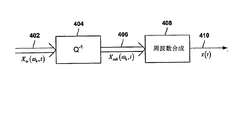
通常、周波数領域符号化システムは、対応する周波数領域復号化システムを有する。図4は、図2において示される周波数領域音声符号器と共に用いるのに適している周波数領域音声復号器の全体的な構造を示すブロック図を示す。図4において、信号Xin(ωk,t)402が、「Q-1」を付されたブロック404に入力され、ブロック404は、符号化されたデジタル信号を取り込み、そのデータを変換して、周波数合成のための1組の適切な入力に戻す。図4において、周波数領域符号化信号Xsub(ωk,t)406(ただし、k=0、1、2、...、N−1)が、Q-1ブロック404から出力され、「周波数合成」を付されたブロック406に入力され、そのブロック406において、信号Xsub(ωk,t)406(ただし、k=0、1、2、...、N−1)は、サンプリングされた音声時間波形x(t)410に再構成される。
Usually, the frequency domain coding system has a corresponding frequency domain decoding system. FIG. 4 shows a block diagram illustrating the overall structure of a frequency domain speech decoder suitable for use with the frequency domain speech encoder shown in FIG. In FIG. 4, a signal X in (ω k , t) 402 is input to a
図5は、図4に示される周波数領域音声復号器において音声信号の周波数合成を実行するのに適しているフィルタバンクシステムを示す。集合的な1組の信号Xsub(ωk,t)406(ただし、k=0、1、2、...、N−1)がアップサンプリングされ(502)、N個のバンドパスフィルタGk504を通じて送られ、その中心周波数はωkであり、その通過帯域は、表現されるべき音声周波数の所望の帯域を含む。その出力xk(t)506は合算され(508)、サンプリングされた音声時間波形x(t)410が再構成される。バンドパスフィルタ504を適切に設計し、元の周波数解析データを細かく量子化することによって、サンプリングされた音声時間波形x(t)410は、ごくわずかな量の誤差しか含むことなく、再構成することができる。
FIG. 5 shows a filter bank system suitable for performing frequency synthesis of speech signals in the frequency domain speech decoder shown in FIG. A collective set of signals X sub (ω k , t) 406 (where k = 0, 1, 2,..., N−1) is upsampled (502) and N bandpass filters G sent through k 504, its center frequency is ω k , and its passband includes the desired band of the audio frequency to be represented. The outputs x k (t) 506 are summed (508) to reconstruct the sampled audio time waveform x (t) 410. By properly designing the
[本発明の周波数領域音響エコーキャンセラ実施形態]
デジタル伝送を使用する音声会議通信システムでは、MPEG2及びAACに基づく周波数領域符号器/復号器のような、周波数領域符号器/復号器を用いることによって音声信号を圧縮することにより、高品質の音声伝送のために必要とされるビットレートを低減するのが一般的である。伝送前に、音声信号は最初に周波数領域符号器を通じて送られ、その後、受信時に、周波数領域復号器を通じて送られる。周波数領域符号器は、音声信号を送信する前に、送出される音声信号を圧縮されたデジタル音声信号に変換し、周波数領域復号器は、圧縮されている受信デジタル音声信号を解凍して、ラウドスピーカに送ることができるアナログ音声信号を復元する。
[Frequency Domain Acoustic Echo Canceller Embodiment of the Present Invention]
In audio conferencing communication systems using digital transmission, high quality audio is obtained by compressing the audio signal by using a frequency domain encoder / decoder, such as a frequency domain encoder / decoder based on MPEG2 and AAC. It is common to reduce the bit rate required for transmission. Prior to transmission, the speech signal is first sent through a frequency domain encoder and then upon reception through a frequency domain decoder. The frequency domain encoder converts the transmitted audio signal into a compressed digital audio signal before transmitting the audio signal, and the frequency domain decoder decompresses the compressed received digital audio signal to produce a loudspeaker. Restore the analog audio signal that can be sent to the speaker.
図6は、音響エコーキャンセラ及び周波数領域符号器/復号器を使用する、図1A及び図1Bに示される例示的な2地点電話会議通信システムの概略図である。部屋2の104内の周波数領域符号器602は、音声信号源118から生じる音声信号をデジタル化及び圧縮し、圧縮されたデジタル音声信号を、部屋1の102内の周波数領域復号器604に送信する。周波数領域復号器604は、圧縮されている受信デジタル音声信号を解凍することによって、アナログ音声信号を復元し、復元された音声信号は、離散時間形式において、適応フィルタ138に送られ、ラウドスピーカ114に送る前に、アナログ形式に変換される。エコー推定値信号
FIG. 6 is a schematic diagram of the exemplary two point teleconferencing communication system shown in FIGS. 1A and 1B using an acoustic echo canceller and a frequency domain encoder / decoder. The
146がエコー信号yin(t)126から減算され、結果として生成された誤差音声信号ein(t)152が、部屋1 102内の周波数領域符号器606に送られる。誤差音声信号ein(t)152は、デジタル化及び圧縮され、部屋2の104内の周波数領域復号器608に送信され、そこで、誤差音声信号ein(t)152は、離散時間信号に復元され、アナログ形式に変換され、ラウドスピーカ116に送られる。
146 is subtracted from the echo signal y in (t) 126 and the resulting error speech signal e in (t) 152 is sent to the
図7は、図6に示される、周波数領域符号器/復号器に基づく例示的な2地点音声会議通信システムの部屋1のさらに詳細な概略図を示す。部屋1の102において点線の長方形として示される周波数領域符号器/復号器700は、周波数領域符号器702と、周波数領域復号器704とを備える。周波数領域符号器702は、音声信号が部屋2に送信される前に、音声信号をデジタル化及び圧縮し、周波数領域復号器704は、圧縮されている受信デジタル音声信号を解凍することによって、部屋2から受信される音声信号を復元する。
FIG. 7 shows a more detailed schematic diagram of
図2において先に示されたように、図7に示される周波数領域符号器702は、周波数解析ステージ706及び量子化器708を備えており、量子化器は知覚モデル(図7には示されない)によって制御される。周波数解析ステージ706は、バンドパスフィルタのアレイ、すなわち図3に示されるフィルタバンクに類似のフィルタバンクを使用することによって、入力音声信号を周波数領域に変換し、入力音声信号を、太い矢印としてまとめて示される、複数の類似の帯域制限された信号710、すなわち部分帯域に分離する。各部分帯域は、入力音声信号の周波数範囲全体の周波数サブセットを含む。各部分帯域710内の分離された周波数成分は量子化器708に送られ、そこで、部分帯域は量子化及び符号化される。部分帯域は、量子化誤差が強い音声信号成分によってマスクされるように量子化される。図2に示されるように、音声信号内の情報ビットを捨てるために、知覚符号化が用いられており、知覚符号化は、信号が単一の音声波形に再構成されるときに、聞き取られる歪みを増大させることなく、音声信号のデータ速度を低減するように設計される。図7に示される概略図を簡単にするために、知覚モデル計算を省略した。しかしながら、量子化器を制御するために、通常知覚モデル計算が用いられる。可変ビット割当てを用いて信号が符号化され、一般的に、人の聴覚が最も敏感である中央の周波数範囲において、サンプル当たり、より多くのビットが用いられ、中央の周波数範囲において、より細かい分解能が与えられている。
As previously indicated in FIG. 2, the
その後、圧縮されたデジタル音声信号は、部屋2内の周波数領域復号器に送信され、そこで、圧縮された音声信号は復元されることができる。部屋1の102では、復号器704が部屋2からの圧縮された入力音声信号に関して逆演算を実行する。復号器704は、逆量子化器712を備えており、逆量子化器において、量子化されている受信音声信号が逆量子化され、適切な共通振幅スケールにおいて、まとめて太い矢印として示される部分帯域716が生成される。部分帯域は周波数合成ステージ714に送られ、そこで、部分帯域は、たとえば、図5に示されるように、元の周波数帯域の場所にアップサンプリングすることによって周波数シフトされ、フィルタバンクを通じて送られ、単一の音声波形に合算され、変換されて、時間領域に戻される。解析及び合成フィルタバンク、並びに周波数領域符号器/復号器によって実行される圧縮及び解凍ルーチンは、電話会議通信システムの中に遅延をもたらすことに留意されたい。
The compressed digital audio signal is then sent to a frequency domain decoder in
本発明の種々の実施形態は、音響エコーキャンセラ機能を含む音声会議通信システムのための周波数領域符号器/復号器に向けられる。音声会議通信システムに組み込まれる周波数領域符号器/復号器において一連の部分帯域に分割されるときに、音響エコーがキャンセルされる。畳み込みは線形演算であり、周波数解析及び周波数合成ステージも線形演算を利用するので、音響エコーキャンセレーションは、周波数領域において実行することができる。音響エコーキャンセレーションを周波数領域符号器/復号器に組み込むことによって、音響エコーキャンセレーションを周波数領域において実行することができ、その際に、音響エコーキャンセラのための冗長な音声信号変換装置を設ける必要はない。 Various embodiments of the present invention are directed to a frequency domain encoder / decoder for an audio conferencing communication system that includes an acoustic echo canceller function. Acoustic echo is canceled when divided into a series of sub-bands in a frequency domain encoder / decoder incorporated in an audio conference communication system. Since convolution is a linear operation and the frequency analysis and frequency synthesis stages also use linear operation, acoustic echo cancellation can be performed in the frequency domain. By incorporating acoustic echo cancellation into the frequency domain encoder / decoder, acoustic echo cancellation can be performed in the frequency domain, with the need to provide a redundant audio signal converter for the acoustic echo canceller. There is no.
本発明では、音響エコーキャンセラは、部分帯域が音声会議通信システム内の周波数領域復号器内にある間に、一連の部分帯域に分割される音声信号を受信する。音響エコーキャンセラは、音声会議通信システム内の周波数領域符号器に一連の部分帯域を出力する。図8は、1つの例示的な2地点電話会議通信システムの部屋1内の周波数領域符号器/復号器に組み込まれ、本発明の一実施形態を表す音響エコーキャンセラの概略図を示す。部屋1の800は、点線の長方形として表される周波数領域符号器/復号器802と、ラウドスピーカ804と、マイクロフォン806とを備える。周波数領域符号器/復号器802は、周波数領域符号器808と、周波数領域復号器810と、破線の長方形によって表される音響エコーキャンセラ812とを備える。部屋2から入ってくる圧縮されたデジタル音声信号Xin(ωk,t)814が、周波数復号器810に入力される。デジタル音声信号Xin(ωk,t)814、すなわち周波数領域の音声信号は圧縮され、逆量子化器816によって受信され、部分帯域信号Xsub(ωk,t)818として図8において示される、一連の部分帯域信号に変換される。
In the present invention, the acoustic echo canceller receives an audio signal that is divided into a series of subbands while the subbands are in a frequency domain decoder within the audio conference communication system. The acoustic echo canceller outputs a series of partial bands to a frequency domain encoder in the audio conference communication system. FIG. 8 shows a schematic diagram of an acoustic echo canceller incorporated in a frequency domain encoder / decoder in
音声信号Xsub(ωk,t)818は2つの場所、すなわち周波数合成ステージ820及び音響エコーキャンセラ812に出力される。周波数合成ステージ820は、音声信号Xsub(ωk,t)818を音声信号xin(t)822に変換する。音声信号Xsub(ωk,t)818は、再構成された1組のバンドパスフィルタ出力であり、音声信号xin(t)822は、単一の離散時間領域信号であることに留意されたい。音声信号xin(t)822は、周波数領域復号器810から出力され、デジタル/音声変換器(図8には示されない)を通じて送られ、その後、ラウドスピーカ804に送られ、部屋1の700の中に音響信号xout(t)823として送出される。マイクロフォン806の出力はエコー信号yin(t)826であり、これは、音声信号xin(t)822とインパルス応答hRoom1(t)824との畳み込みである。エコー信号yin(t)826は、周波数領域符号器808に入力され、周波数解析ステージ828によって変換され、一連の部分帯域、すなわちエコー信号Ysub(ωk,t)830に分割され、そしてN個の部分帯域信号のベクトル減算を表す加算接合部832に送られる。
The audio signal X sub (ω k , t) 818 is output to two locations, namely the
音響エコーキャンセラ812は、音声信号Xsub(ωk,t)818を受信し、部分帯域信号に1組のフィルタを適用する。1組のフィルタは、図8において、フィルタリング行列
The
を付されたブロック834によって表される。フィルタリング行列
It is represented by a
834は、図1Bを参照しながら先に説明された 834 was previously described with reference to FIG. 1B
の演算に等価である。フィルタリング行列 Is equivalent to Filtering matrix
834によって表されるフィルタは、音声信号Xsub(ωk,t)818に適用されて、エコー信号推定値 The filter represented by 834 is applied to the audio signal X sub (ω k , t) 818 to provide an echo signal estimate.
838が生成され、これはフィルタリング行列 838 is generated, which is the filtering matrix
834から出力され、ベクトル加算接合部832によって受信される。エコー信号推定値
834 and received by the
838がエコー信号Ysub(ωk,t)830から減算され、誤差音声信号Esub(ωk,t)840が生成され、これが、フィードバックを与えるために適応フィルタ834に戻され、また量子化器842にも送られ、ここで、誤差音声信号Esub(ωk,t)840は量子化され、その結果が、Ein(ωk,t)844として表される。誤差音声信号Ein(ωk,t)844は、周波数領域符号器808から出力され、部屋2に伝送される。
838 is subtracted from the echo signal Y sub (ω k , t) 830 to produce an error speech signal E sub (ω k , t) 840 that is returned to the
誤差信号の量子化は知覚モデルによって導かれる。部屋2からの信号が存在しない場合に、信号yin(t)826はまさに、部屋2に送られることになる所望の信号であるので、知覚モデルは一般的に、信号yin(t)826から計算される高分解能スペクトルによって制御される。したがって、信号yin(t)826は、正確に量子化され、符号化される必要がある。部屋1において誰も話をしていない場合には、信号Esub(ωk,t)840はキャンセルされることが望ましいエコーを表すので、信号Esub(ωk,t)840を正確に量子化することは重要ではなくなる。この場合、誤差信号Esub(ωk,t)840は、信号yin(t)826を減衰させて、フィルタリングしたものであるので、それでも、信号yin(t)826に基づく知覚モデルを使用することは妥当である。図8に示される量子化演算は、音声会議信号の品質を高めるためのさらに別の機会をもたらす。部分帯域信号に関する音響エコーキャンセレーションの技術分野において、量子化過程の一部としてよく知られている非線形エコー抑圧技法を実施することによって、残留音響エコーのさらなるマスキングを組み込むことができる。
The quantization of the error signal is guided by a perceptual model. In the absence of a signal from
線形フィルタリングの前後いずれかにおいて、周波数解析を実行することができる。図9Aは、線形フィルタリングと、それに続く周波数解析の概略図を示す。図9Aでは、周波数解析は、畳み込み Frequency analysis can be performed either before or after linear filtering. FIG. 9A shows a schematic diagram of linear filtering followed by frequency analysis. In FIG. 9A, frequency analysis is convolution.
の後に実行され、部分帯域信号 Subband signal that is executed after
が得られる。図9Bは、図9A及び図9Bの出力が等価になるように、周波数解析の後に部分帯域信号の線形フィルタリングを実施する概略図を示す。C. A. Lanciani及びR. W. Schafer著「Psychoacoustically-based processing of MPEG-I layer 1-2 signals」(IEEE First Workshop on Multimedia Signal Processing, June 1997, pp 53-58)、並びにC. A. Lanciani及びR. W. Schafer著「Subband-domain filtering of MPEG audio signals」(Proc. IEEE ICASSP '99, vol. 2, March 1999, pp 917-920)において、Lanciani及びSchaferは、周波数解析が線形フィルタリング前に実行されるときに、部分帯域信号に適用することができる1組のバンドパスフィルタを見つけることができることを示した。フィルタリング行列 Is obtained. FIG. 9B shows a schematic diagram of performing linear filtering of the subband signal after frequency analysis so that the outputs of FIGS. 9A and 9B are equivalent. "Psychoacoustically-based processing of MPEG-I layer 1-2 signals" by CA Lanciani and RW Schafer (IEEE First Workshop on Multimedia Signal Processing, June 1997, pp 53-58) and "Subband-domain by CA Lanciani and RW Schafer" In "Filtering of MPEG audio signals" (Proc. IEEE ICASSP '99, vol. 2, March 1999, pp 917-920), Lanciani and Schafer are able to generate subband signals when frequency analysis is performed before linear filtering. It has been shown that a set of bandpass filters can be found that can be applied. Filtering matrix
によって表される、この1組の線形フィルタを求めることは、図9Bにおいて示される線形フィルタを実現するのに重要である。フィルタリング行列 Determining this set of linear filters represented by is important for implementing the linear filter shown in FIG. 9B. Filtering matrix
にXsub(ωk,t)が入力されるとき、図9Bにおいて得られる Is obtained in FIG. 9B when X sub (ω k , t) is input to
が図9Aにおいて示される結果と等価になるように、フィルタリング行列 Is equivalent to the result shown in FIG. 9A
を調整することができる。 Can be adjusted.
一般的に、図9Bの出力信号が図9Aの出力信号に等価になる場合、 In general, if the output signal of FIG. 9B is equivalent to the output signal of FIG. 9A,
の各個別の部分帯域は、解析/合成フィルタバンクシステムのエイリアスキャンセレーション特性を保持するために、Xsub(ωk,t)の全ての部分帯域に依存する。しかしながら、C. A. Lanciani及びR. W. Schafer著「Subband-domain filtering of MPEG audio signals」(Proc. IEEE ICASSP '99, vol. 2, March 1999, pp 917-920)において、Lanciani及びSchaferは、音声符号器において用いられるタイプのフィルタバンクの場合、隣接する部分帯域の影響しか含む必要がないことを示した。フィルタリング行列 Each individual sub- band depends on all sub-bands of X sub (ω k , t) to preserve the alias cancellation characteristics of the analysis / synthesis filter bank system. However, according to CA Lanciani and RW Schafer's “Subband-domain filtering of MPEG audio signals” (Proc. IEEE ICASSP '99, vol. 2, March 1999, pp 917-920), Lanciani and Schafer are used in speech encoders. For certain types of filter banks, it has been shown that only the effects of adjacent subbands need be included. Filtering matrix
を含むインパルス応答は、音響エコーキャンセレーションの技術分野においてよく知られている技法を用いて適応させることができ、バンドパスフィルタが音声信号のサンプリングレートの1/N倍であるサンプリングレートにおいて動作するという利点、及び部分帯域信号が、その制限された周波数帯域にわたって比較的平坦なスペクトルを有するという利点がある。 Can be adapted using techniques well known in the art of acoustic echo cancellation, and the bandpass filter operates at a sampling rate that is 1 / N times the sampling rate of the audio signal. And the advantage that the subband signal has a relatively flat spectrum over its limited frequency band.
電話会議通信システム内の周波数領域符号器/復号器によって実行される音声信号処理を用いて、音声信号が異なる場所に伝送される前に、音声信号内の可聴背景雑音の量を低減することもできる。1つの手法は、ウィーナタイプのフィルタリングを用いることである。ウィーナフィルタは、各信号の周波数スペクトルに基づいて信号を分離する。ウィーナフィルタは、主に音声信号を含む周波数を通し、主に雑音を含む周波数を遮断する。さらに、各周波数におけるウィーナフィルタの利得は、各周波数における音声信号及び雑音の相対的な量によって決定される。ウィーナフィルタは、音声信号と共に、信号対雑音比を最大にする。ウィーナタイプのフィルタリングを使用するために、信号は周波数領域内にある必要があり、且つ現在の場所内の雑音スペクトルがわかっている必要があり、それにより、ウィーナフィルタの周波数応答を計算することができる。本発明の現在の実施形態では、音響エコーキャンセラの適応フィルタを使用して、周波数領域符号器/復号器が配置される場所における雑音スペクトルを推定することによって、音声信号においてウィーナタイプのフィルタリングを実行し、音声信号が別の場所に伝送される前に、雑音を低減することができる。 Audio signal processing performed by a frequency domain encoder / decoder in a teleconference communication system can also be used to reduce the amount of audible background noise in the audio signal before it is transmitted to different locations. it can. One approach is to use Wiener type filtering. A Wiener filter separates signals based on the frequency spectrum of each signal. The Wiener filter passes frequencies that mainly contain audio signals and blocks frequencies that mainly contain noise. Furthermore, the gain of the Wiener filter at each frequency is determined by the relative amount of speech signal and noise at each frequency. The Wiener filter, along with the audio signal, maximizes the signal-to-noise ratio. In order to use Wiener-type filtering, the signal must be in the frequency domain and the noise spectrum in the current location must be known, thereby calculating the frequency response of the Wiener filter. it can. In the current embodiment of the present invention, an acoustic echo canceller adaptive filter is used to perform Wiener-type filtering on the speech signal by estimating the noise spectrum where the frequency domain encoder / decoder is located. However, noise can be reduced before the audio signal is transmitted to another location.
本発明は、特定の実施形態に関して説明されてきたが、本発明がこの実施形態に限定されることを意図していない。本発明の精神の中にある変更が、当業者には明らかになるであろう。たとえば、電話会議通信システム内の場所の数は、2つよりも多くの数にすることができる。例示を明確にするために、上記の説明における例の多くにおいて、2つの場所が説明される。各場所において用いられるマイクロフォン及びラウドスピーカの数も変更することができる。例示を明確にするために、上記の説明における例の多くにおいて、1つのマイクロフォン及び1つのラウドスピーカが用いられる。各場所において、多数のマイクロフォン及び/又は多数のラウドスピーカを用いることができる。多数のマイクロフォン及び多数のラウドスピーカを有する場所の場合のインパルス応答はさらに複雑になることがあり、それに応じて、フィルタリング係数を調整して、音声信号受信場所のインパルス応答の変化に適応フィルタを適応させるために、さらに多くの計算が実行される必要があることに留意されたい。 Although the present invention has been described in terms of a particular embodiment, it is not intended that the invention be limited to this embodiment. Modifications within the spirit of the invention will be apparent to those skilled in the art. For example, the number of locations in the conference call communication system can be more than two. For clarity of illustration, two locations are described in many of the examples in the above description. The number of microphones and loudspeakers used at each location can also be varied. For clarity of illustration, one microphone and one loudspeaker are used in many of the examples in the above description. Multiple microphones and / or multiple loudspeakers can be used at each location. The impulse response for locations with a large number of microphones and a large number of loudspeakers can be even more complex, and the filtering coefficients can be adjusted accordingly to adapt the adaptive filter to changes in the impulse response at the location where the audio signal is received. Note that more calculations need to be performed in order to do so.
これまでの詳細な説明は、本発明を完全に理解してもらうために、例示するのを目的として、特有の用語を使用した。しかしながら、本発明を実施するのに、具体的な細部が不要であることは当業者には明らかであろう。したがって、本発明の具体的な実施形態のこれまでの説明は、例示し、説明するために提示される。それらの実施形態は、本発明を余す所なく述べることや、本発明を開示されるのと全く同じ形態に限定することは意図していない。上記の教示に鑑みて、数多くの変更及び変形が可能であることは明らかである。それらの実施形態は、本発明の原理及びその実用的な用途を最もわかりやすく説明し、それにより、当業者が、意図している特定の用途に相応しいように、本発明及び種々の実施形態に種々の変更を加えて最大限に利用することができるようにするために選択され、説明された。 In the preceding detailed description, specific terminology has been used for the purpose of illustration in order to provide a thorough understanding of the present invention. However, it will be apparent to one skilled in the art that the specific details are not required in order to practice the invention. Thus, the foregoing descriptions of specific embodiments of the present invention are presented for purposes of illustration and description. These embodiments are not intended to be exhaustive or to limit the invention to the precise form disclosed. Obviously, many modifications and variations are possible in view of the above teachings. These embodiments most clearly describe the principles of the invention and its practical application, so that those skilled in the art will recognize the invention and various embodiments as appropriate for the particular application intended. Various changes have been selected and described to enable maximum utilization.
Claims (10)
第2の場所(104)から受信される量子化された周波数領域音声信号(814)を1組の第2の場所の部分帯域信号(818)に変換する復号器(810)と、
前記第1の場所(800)から受信される時間領域エコー音声信号(826)を1組の第1の場所の周波数領域エコー部分帯域信号(830)に変換する符号器(808)と、
前記1組の第2の場所の部分帯域信号(818)及び前記1組の第1の場所の周波数領域エコー部分帯域信号(830)に基づいて1組の周波数領域誤差音声部分帯域信号(840)を生成し、前記生成された1組の周波数領域誤差音声部分帯域信号(840)に基づいて、第1の場所のインパルス応答(824)を追跡する音響エコーキャンセラ(812)と、
前記第2の場所(104)に、量子化された周波数領域誤差音声部分帯域信号(844)を出力する音声信号出力とを備えることを特徴とする周波数領域符号器/復号器構成要素。 A frequency domain encoder / decoder component (802) of an audio conferencing communication system at a first location (800), the frequency domain encoder / decoder component (802) comprising:
A decoder (810) that converts the quantized frequency domain audio signal (814) received from the second location (104) into a set of second location subband signals (818);
An encoder (808) for converting a time domain echo audio signal (826) received from the first location (800) into a set of frequency domain echo subband signals (830) of the first location;
A set of frequency domain error speech subband signals (840) based on the set of second location subband signals (818) and the set of first location frequency domain echo subband signals (830). An acoustic echo canceller (812) that tracks a first location impulse response (824) based on the generated set of frequency domain error speech subband signals (840);
A frequency domain encoder / decoder component comprising a speech signal output for outputting a quantized frequency domain error speech subband signal (844) at the second location (104).
前記復号器(810)は、
前記第2の場所(104)から受信される前記量子化された周波数領域音声信号(814)を前記1組の第2の場所の部分帯域信号(818)に変換するための逆量子化器(816)と、
前記第2の場所の部分帯域信号(818)を単一のサンプリングされた音声時間領域波形(822)に変換するための周波数合成ステージ(820)とを備えることを特徴とする、請求項1に記載の周波数領域符号器/復号器構成要素。 A frequency domain encoder / decoder component (802), comprising:
The decoder (810)
An inverse quantizer for converting the quantized frequency domain speech signal (814) received from the second location (104) into the set of second location subband signals (818); 816),
The frequency synthesis stage (820) for converting the second location sub-band signal (818) into a single sampled speech time domain waveform (822). A frequency domain encoder / decoder component as described.
前記符号器(808)は、
前記第1の場所(800)から受信される前記時間領域エコー音声信号(826)を、前記音響エコーキャンセラ(812)に入力される、前記1組の第1の場所の周波数領域エコー部分帯域信号(830)に変換するための周波数解析ステージ(828)と、
前記音響エコーキャンセラ(812)によって生成される前記1組の周波数領域誤差音声部分帯域信号(840)を、前記第2の場所(104)に出力される前記量子化された周波数領域誤差音声部分帯域信号(844)に変換するための量子化器(842)とを備えることを特徴とする請求項1に記載の周波数領域符号器/復号器構成要素。 A frequency domain encoder / decoder component (802), comprising:
The encoder (808)
The set of first location frequency domain echo sub-band signals, wherein the time domain echo audio signal (826) received from the first location (800) is input to the acoustic echo canceller (812). A frequency analysis stage (828) for conversion to (830);
The set of frequency domain error speech subband signals (840) generated by the acoustic echo canceller (812) is output to the second location (104) as the quantized frequency domain error speech subband. The frequency domain encoder / decoder component of claim 1, comprising a quantizer (842) for converting to a signal (844).
前記1組の量子化された周波数領域誤差音声部分帯域信号(840)が前記第2の場所(104)に出力される前に、前記1組の周波数領域誤差音声部分帯域信号(840)に関して、
知覚符号化、
雑音低減、及び
ウィーナタイプフィルタリングのうちの1つ又は複数が実施されることを特徴とする請求項1に記載の周波数領域符号器/復号器構成要素。 A frequency domain encoder / decoder component (802), comprising:
Before the set of quantized frequency domain error speech subband signals (840) is output to the second location (104), with respect to the set of frequency domain error speech subband signals (840),
Perceptual coding,
The frequency domain encoder / decoder component of claim 1, wherein one or more of noise reduction and Wiener type filtering is implemented.
前記音響エコーキャンセラ(812)は、
前記生成された1組の周波数領域誤差音声部分帯域信号(840)に基づいて前記第1の場所のインパルス応答(824)を追跡し、1組の第1の場所のエコー部分帯域信号推定値(838)を出力する適応フィルタ(834)と、
前記受信された1組の第1の場所の周波数領域エコー部分帯域信号(830)から前記受信された1組の第1の場所のエコー部分帯域信号推定値(838)を減算し、前記1組の周波数領域誤差音声部分帯域信号(840)を出力する加算接合部(832)とをさらに備えることを特徴とする請求項1に記載の周波数領域符号器/復号器構成要素。 A frequency domain encoder / decoder component (802), comprising:
The acoustic echo canceller (812)
Based on the generated set of frequency domain error speech subband signals (840), the impulse response (824) of the first location is tracked and an echo subband signal estimate of the set of first locations ( An adaptive filter (834) for outputting 838);
Subtracting the received set of first location echo subband signal estimates (838) from the received set of first location frequency domain echo subband signals (830); The frequency domain encoder / decoder component of claim 1, further comprising a summing junction (832) for outputting a frequency domain error speech subband signal (840) of
復号器(810)と、符号器(808)と、音響エコーキャンセラ(812)とを備える周波数領域符号器/復号器(802)を第1の場所(800)に設け、
第2の場所(104)から前記復号器(810)に、量子化された周波数領域音声信号(814)を送信し、前記量子化された周波数領域音声信号(814)を1組の第2の場所の部分帯域信号(818)に変換し、
前記第1の場所(800)から前記符号器(808)に、時間領域エコー音声信号(826)を送信し、前記時間領域エコー音声信号(826)を1組の第1の場所の周波数領域エコー部分帯域信号(830)に変換し、
前記音響エコーキャンセラ(812)によって、前記1組の第2の場所の部分帯域信号(818)及び前記1組の第1の場所の周波数領域エコー部分帯域信号(830)に基づいて1組の周波数領域誤差音声部分帯域信号(840)を生成し、前記生成された1組の周波数領域誤差部分帯域信号(840)に基づいて、第1の場所のインパルス応答(824)を追跡し、
前記第2の場所(104)に、量子化された周波数領域誤差音声部分帯域信号(844)を出力することを含むことを特徴とする方法。 A method for canceling acoustic echo in an audio conference communication system, comprising:
A frequency domain encoder / decoder (802) comprising a decoder (810), an encoder (808), and an acoustic echo canceller (812) is provided at a first location (800);
A quantized frequency domain audio signal (814) is transmitted from a second location (104) to the decoder (810), and the quantized frequency domain audio signal (814) is transmitted to a set of second Converted to a partial band signal (818) of the place,
A time domain echo audio signal (826) is transmitted from the first location (800) to the encoder (808), and the time domain echo audio signal (826) is transmitted to the set of frequency domain echoes of the first location. Convert to partial band signal (830)
A set of frequencies based on the set of second location subband signals (818) and the set of first location frequency domain echo subband signals (830) by the acoustic echo canceller (812). Generating a domain error speech subband signal (840), and tracking a first location impulse response (824) based on the generated set of frequency domain error subband signals (840);
Outputting the quantized frequency domain error speech subband signal (844) to the second location (104).
前記第2の場所(104)から受信される前記量子化された周波数領域音声信号(814)を前記1組の第2の場所の部分帯域信号(818)に変換するための逆量子化器(816)と、
前記第2の場所の部分帯域信号(818)を単一のサンプリングされた音声時間領域波形(822)に変換するための周波数合成ステージ(820)とを備えることを特徴とする、請求項6に記載の方法。 The decoder (810)
An inverse quantizer for converting the quantized frequency domain speech signal (814) received from the second location (104) into the set of second location subband signals (818); 816),
A frequency synthesis stage (820) for converting the second location sub-band signal (818) into a single sampled speech time domain waveform (822). The method described.
前記第1の場所(800)から受信される前記時間領域エコー音声信号(826)を、前記音響エコーキャンセラ(812)に入力される、前記1組の第1の場所の周波数領域エコー部分帯域信号(830)に変換するための周波数解析ステージ(828)と、
前記音響エコーキャンセラ(812)によって生成される前記1組の周波数領域誤差音声部分帯域信号(840)を、前記第2の場所に出力される前記量子化された周波数領域誤差音声部分帯域信号(844)に変換するための量子化器(842)とを備えることを特徴とする請求項6に記載の方法。 The encoder (808)
The set of first location frequency domain echo sub-band signals, wherein the time domain echo audio signal (826) received from the first location (800) is input to the acoustic echo canceller (812). A frequency analysis stage (828) for conversion to (830);
The set of frequency domain error speech subband signals (840) generated by the acoustic echo canceller (812) is output to the second location the quantized frequency domain error speech subband signal (844). And a quantizer (842) for converting to a method.
知覚符号化、
雑音低減、及び
ウィーナタイプフィルタリングのうちの1つ又は複数が実施されることを特徴とする請求項6に記載の方法。 Before the set of quantized frequency domain error speech subband signals (840) is output to the second location (104), with respect to the set of frequency domain error speech subband signals (840),
Perceptual coding,
The method of claim 6, wherein one or more of noise reduction and Wiener type filtering is performed.
前記生成された1組の周波数領域誤差音声部分帯域信号(840)に基づいて前記第1の場所のインパルス応答(824)を追跡し、1組の第1の場所のエコー部分帯域信号推定値(838)を出力する適応フィルタ(834)と、
前記受信された1組の第1の場所の周波数領域エコー部分帯域信号(830)から前記受信された1組の第1の場所のエコー部分帯域信号推定値(838)を減算し、前記1組の周波数領域誤差音声部分帯域信号(840)を出力する加算接合部(832)とをさらに備えることを特徴とする請求項6に記載の方法。 The acoustic echo canceller (812)
Based on the generated set of frequency domain error speech subband signals (840), the impulse response (824) of the first location is tracked and an echo subband signal estimate of the set of first locations ( An adaptive filter (834) for outputting 838);
Subtracting the received set of first location echo subband signal estimates (838) from the received set of first location frequency domain echo subband signals (830); The method of claim 6, further comprising: a summing junction (832) for outputting a frequency domain error speech subband signal (840).
Applications Claiming Priority (2)
| Application Number | Priority Date | Filing Date | Title |
|---|---|---|---|
| US11/546,680 US20080091415A1 (en) | 2006-10-12 | 2006-10-12 | System and method for canceling acoustic echoes in audio-conference communication systems |
| PCT/US2007/021814 WO2008045537A2 (en) | 2006-10-12 | 2007-10-12 | System and method for canceling acoustic echoes in audio-conference communication systems |
Publications (1)
| Publication Number | Publication Date |
|---|---|
| JP2010507105A true JP2010507105A (en) | 2010-03-04 |
Family
ID=39283470
Family Applications (1)
| Application Number | Title | Priority Date | Filing Date |
|---|---|---|---|
| JP2009532431A Withdrawn JP2010507105A (en) | 2006-10-12 | 2007-10-12 | System and method for canceling acoustic echo in an audio conference communication system |
Country Status (4)
| Country | Link |
|---|---|
| US (1) | US20080091415A1 (en) |
| EP (1) | EP2097896A2 (en) |
| JP (1) | JP2010507105A (en) |
| WO (1) | WO2008045537A2 (en) |
Cited By (1)
| Publication number | Priority date | Publication date | Assignee | Title |
|---|---|---|---|---|
| JP2016535850A (en) * | 2013-11-11 | 2016-11-17 | アスティックス ゲーエムベーハー | Measuring device for identifying distances in conductive structures |
Families Citing this family (18)
| Publication number | Priority date | Publication date | Assignee | Title |
|---|---|---|---|---|
| US8982744B2 (en) * | 2007-06-06 | 2015-03-17 | Broadcom Corporation | Method and system for a subband acoustic echo canceller with integrated voice activity detection |
| US8559611B2 (en) * | 2008-04-07 | 2013-10-15 | Polycom, Inc. | Audio signal routing |
| US8208649B2 (en) * | 2009-04-28 | 2012-06-26 | Hewlett-Packard Development Company, L.P. | Methods and systems for robust approximations of impulse responses in multichannel audio-communication systems |
| WO2010146711A1 (en) * | 2009-06-19 | 2010-12-23 | 富士通株式会社 | Audio signal processing device and audio signal processing method |
| US8762158B2 (en) * | 2010-08-06 | 2014-06-24 | Samsung Electronics Co., Ltd. | Decoding method and decoding apparatus therefor |
| US9008302B2 (en) | 2010-10-08 | 2015-04-14 | Optical Fusion, Inc. | Audio acoustic echo cancellation for video conferencing |
| US9749673B2 (en) * | 2011-06-03 | 2017-08-29 | Amg Ip, Llc | Systems and methods for providing multiple audio streams in a venue |
| US9473865B2 (en) * | 2012-03-01 | 2016-10-18 | Conexant Systems, Inc. | Integrated motion detection using changes in acoustic echo path |
| KR20140017338A (en) * | 2012-07-31 | 2014-02-11 | 인텔렉추얼디스커버리 주식회사 | Apparatus and method for audio signal processing |
| US9391724B2 (en) * | 2013-08-16 | 2016-07-12 | Arris Enterprises, Inc. | Frequency sub-band coding of digital signals |
| US9691378B1 (en) * | 2015-11-05 | 2017-06-27 | Amazon Technologies, Inc. | Methods and devices for selectively ignoring captured audio data |
| GB2545263B (en) * | 2015-12-11 | 2019-05-15 | Acano Uk Ltd | Joint acoustic echo control and adaptive array processing |
| CN111149370B (en) * | 2017-09-29 | 2021-10-01 | 杜比实验室特许公司 | Howling detection in a conferencing system |
| CN111263252B (en) * | 2018-11-30 | 2021-11-30 | 上海哔哩哔哩科技有限公司 | Live broadcast wheat-connecting silencing method and system and storage medium |
| US11017790B2 (en) * | 2018-11-30 | 2021-05-25 | International Business Machines Corporation | Avoiding speech collisions among participants during teleconferences |
| US11626093B2 (en) * | 2019-07-25 | 2023-04-11 | Unify Patente Gmbh & Co. Kg | Method and system for avoiding howling disturbance on conferences |
| CN113113035A (en) * | 2020-01-10 | 2021-07-13 | 阿里巴巴集团控股有限公司 | Audio signal processing method, device and system and electronic equipment |
| CN116612778B (en) * | 2023-07-18 | 2023-11-14 | 腾讯科技(深圳)有限公司 | Echo and noise suppression method, related device and medium |
Family Cites Families (10)
| Publication number | Priority date | Publication date | Assignee | Title |
|---|---|---|---|---|
| US4644108A (en) * | 1982-10-27 | 1987-02-17 | International Business Machines Corporation | Adaptive sub-band echo suppressor |
| US5477534A (en) * | 1993-07-30 | 1995-12-19 | Kyocera Corporation | Acoustic echo canceller |
| JP3199155B2 (en) * | 1995-10-18 | 2001-08-13 | 日本電信電話株式会社 | Echo canceller |
| US5970154A (en) * | 1997-06-16 | 1999-10-19 | Industrial Technology Research Institute | Apparatus and method for echo cancellation |
| US5857167A (en) * | 1997-07-10 | 1999-01-05 | Coherant Communications Systems Corp. | Combined speech coder and echo canceler |
| US6718036B1 (en) * | 1999-12-15 | 2004-04-06 | Nortel Networks Limited | Linear predictive coding based acoustic echo cancellation |
| US6434235B1 (en) * | 2000-08-01 | 2002-08-13 | Lucent Technologies Inc. | Acoustic echo canceler |
| US7062040B2 (en) * | 2002-09-20 | 2006-06-13 | Agere Systems Inc. | Suppression of echo signals and the like |
| US7471788B2 (en) * | 2002-11-25 | 2008-12-30 | Intel Corporation | Echo cancellers for sparse channels |
| US7454010B1 (en) * | 2004-11-03 | 2008-11-18 | Acoustic Technologies, Inc. | Noise reduction and comfort noise gain control using bark band weiner filter and linear attenuation |
-
2006
- 2006-10-12 US US11/546,680 patent/US20080091415A1/en not_active Abandoned
-
2007
- 2007-10-12 EP EP07852698A patent/EP2097896A2/en not_active Withdrawn
- 2007-10-12 JP JP2009532431A patent/JP2010507105A/en not_active Withdrawn
- 2007-10-12 WO PCT/US2007/021814 patent/WO2008045537A2/en active Application Filing
Cited By (4)
| Publication number | Priority date | Publication date | Assignee | Title |
|---|---|---|---|---|
| JP2016535850A (en) * | 2013-11-11 | 2016-11-17 | アスティックス ゲーエムベーハー | Measuring device for identifying distances in conductive structures |
| US10436889B2 (en) | 2013-11-11 | 2019-10-08 | Astyx Gmbh | Measuring device for determining a distance in a conducting structure |
| US11275167B2 (en) | 2013-11-11 | 2022-03-15 | Astyx MPS GmbH | Measuring device for determining a distance in a conducting structure |
| US11644558B2 (en) | 2013-11-11 | 2023-05-09 | Astyx MPS GmbH | Measuring device for determining a distance in a conducting structure |
Also Published As
| Publication number | Publication date |
|---|---|
| EP2097896A2 (en) | 2009-09-09 |
| US20080091415A1 (en) | 2008-04-17 |
| WO2008045537A3 (en) | 2008-07-17 |
| WO2008045537A2 (en) | 2008-04-17 |
Similar Documents
| Publication | Publication Date | Title |
|---|---|---|
| JP2010507105A (en) | System and method for canceling acoustic echo in an audio conference communication system | |
| US8977545B2 (en) | System and method for multi-channel noise suppression | |
| US7010119B2 (en) | Echo canceller with reduced requirement for processing power | |
| CN1719516B (en) | Adaptive filter device and adaptive filtering method | |
| JP4611423B2 (en) | Method and system for low delay echo cancellation operation | |
| EP1208689B1 (en) | Acoustical echo cancellation device | |
| JP5671147B2 (en) | Echo suppression including modeling of late reverberation components | |
| US8676571B2 (en) | Audio signal processing system and audio signal processing method | |
| US6628781B1 (en) | Methods and apparatus for improved sub-band adaptive filtering in echo cancellation systems | |
| KR20130108063A (en) | Multi-microphone robust noise suppression | |
| CN104052526A (en) | Clipping Based On Cepstral Distance For Acoustic Echo Canceller | |
| EP1638079B1 (en) | Method and system for active noise cancellation | |
| US7062039B1 (en) | Methods and apparatus for improving adaptive filter performance by inclusion of inaudible information | |
| KR20060042492A (en) | Method and apparatus for eliminating acoustic echo in mobile terminal | |
| Yang | Multilayer adaptation based complex echo cancellation and voice enhancement | |
| US8194850B2 (en) | Method and apparatus for voice communication | |
| US8879721B2 (en) | Audio communication system | |
| JP2000134138A (en) | Non-delay system to cancel subband echo | |
| Eneroth | Stereophonic acoustic echo cancellation: Theory and implementation | |
| JP2007151038A (en) | Sound processing apparatus | |
| EP2568619B1 (en) | Echo cancelling-codec | |
| WO2008086920A1 (en) | Disturbance reduction in digital signal processing | |
| Wang et al. | A subband adaptive learning algorithm for microphone array based speech enhancement | |
| CN117542342A (en) | Echo cancellation method based on self-adaptive filtering and neural network | |
| CN117351971A (en) | Audio coding and decoding system with built-in DSP and audio algorithm and audio coder and decoder |
Legal Events
| Date | Code | Title | Description |
|---|---|---|---|
| A761 | Written withdrawal of application |
Free format text: JAPANESE INTERMEDIATE CODE: A761 Effective date: 20100212 |