JP2010506560A - Method and apparatus for assembling a rotor of a permanent magnet motor - Google Patents
Method and apparatus for assembling a rotor of a permanent magnet motor Download PDFInfo
- Publication number
- JP2010506560A JP2010506560A JP2009532531A JP2009532531A JP2010506560A JP 2010506560 A JP2010506560 A JP 2010506560A JP 2009532531 A JP2009532531 A JP 2009532531A JP 2009532531 A JP2009532531 A JP 2009532531A JP 2010506560 A JP2010506560 A JP 2010506560A
- Authority
- JP
- Japan
- Prior art keywords
- rotor
- stack
- fixture
- type stack
- compression ring
- Prior art date
- Legal status (The legal status is an assumption and is not a legal conclusion. Google has not performed a legal analysis and makes no representation as to the accuracy of the status listed.)
- Withdrawn
Links
- 238000000034 method Methods 0.000 title claims abstract description 7
- 230000006835 compression Effects 0.000 claims abstract description 22
- 238000007906 compression Methods 0.000 claims abstract description 22
- 239000000463 material Substances 0.000 description 5
- 230000004323 axial length Effects 0.000 description 4
- 239000000969 carrier Substances 0.000 description 3
- 229910000531 Co alloy Inorganic materials 0.000 description 1
- 229910000831 Steel Inorganic materials 0.000 description 1
- 239000004809 Teflon Substances 0.000 description 1
- 229920006362 Teflon® Polymers 0.000 description 1
- RTAQQCXQSZGOHL-UHFFFAOYSA-N Titanium Chemical compound [Ti] RTAQQCXQSZGOHL-UHFFFAOYSA-N 0.000 description 1
- QXZUUHYBWMWJHK-UHFFFAOYSA-N [Co].[Ni] Chemical compound [Co].[Ni] QXZUUHYBWMWJHK-UHFFFAOYSA-N 0.000 description 1
- 238000007790 scraping Methods 0.000 description 1
- 239000007779 soft material Substances 0.000 description 1
- 239000010935 stainless steel Substances 0.000 description 1
- 229910001220 stainless steel Inorganic materials 0.000 description 1
- 239000010959 steel Substances 0.000 description 1
- 239000010936 titanium Substances 0.000 description 1
- 229910052719 titanium Inorganic materials 0.000 description 1
Images


Classifications
-
- H—ELECTRICITY
- H02—GENERATION; CONVERSION OR DISTRIBUTION OF ELECTRIC POWER
- H02K—DYNAMO-ELECTRIC MACHINES
- H02K1/00—Details of the magnetic circuit
- H02K1/06—Details of the magnetic circuit characterised by the shape, form or construction
- H02K1/22—Rotating parts of the magnetic circuit
- H02K1/27—Rotor cores with permanent magnets
- H02K1/2706—Inner rotors
- H02K1/272—Inner rotors the magnetisation axis of the magnets being perpendicular to the rotor axis
- H02K1/274—Inner rotors the magnetisation axis of the magnets being perpendicular to the rotor axis the rotor consisting of two or more circumferentially positioned magnets
- H02K1/2753—Inner rotors the magnetisation axis of the magnets being perpendicular to the rotor axis the rotor consisting of two or more circumferentially positioned magnets the rotor consisting of magnets or groups of magnets arranged with alternating polarity
- H02K1/276—Magnets embedded in the magnetic core, e.g. interior permanent magnets [IPM]
- H02K1/2766—Magnets embedded in the magnetic core, e.g. interior permanent magnets [IPM] having a flux concentration effect
- H02K1/2773—Magnets embedded in the magnetic core, e.g. interior permanent magnets [IPM] having a flux concentration effect consisting of tangentially magnetized radial magnets
-
- H—ELECTRICITY
- H02—GENERATION; CONVERSION OR DISTRIBUTION OF ELECTRIC POWER
- H02K—DYNAMO-ELECTRIC MACHINES
- H02K1/00—Details of the magnetic circuit
- H02K1/06—Details of the magnetic circuit characterised by the shape, form or construction
- H02K1/22—Rotating parts of the magnetic circuit
- H02K1/28—Means for mounting or fastening rotating magnetic parts on to, or to, the rotor structures
-
- Y—GENERAL TAGGING OF NEW TECHNOLOGICAL DEVELOPMENTS; GENERAL TAGGING OF CROSS-SECTIONAL TECHNOLOGIES SPANNING OVER SEVERAL SECTIONS OF THE IPC; TECHNICAL SUBJECTS COVERED BY FORMER USPC CROSS-REFERENCE ART COLLECTIONS [XRACs] AND DIGESTS
- Y10—TECHNICAL SUBJECTS COVERED BY FORMER USPC
- Y10T—TECHNICAL SUBJECTS COVERED BY FORMER US CLASSIFICATION
- Y10T29/00—Metal working
- Y10T29/49—Method of mechanical manufacture
- Y10T29/49002—Electrical device making
- Y10T29/49009—Dynamoelectric machine
- Y10T29/49012—Rotor
-
- Y—GENERAL TAGGING OF NEW TECHNOLOGICAL DEVELOPMENTS; GENERAL TAGGING OF CROSS-SECTIONAL TECHNOLOGIES SPANNING OVER SEVERAL SECTIONS OF THE IPC; TECHNICAL SUBJECTS COVERED BY FORMER USPC CROSS-REFERENCE ART COLLECTIONS [XRACs] AND DIGESTS
- Y10—TECHNICAL SUBJECTS COVERED BY FORMER USPC
- Y10T—TECHNICAL SUBJECTS COVERED BY FORMER US CLASSIFICATION
- Y10T29/00—Metal working
- Y10T29/53—Means to assemble or disassemble
- Y10T29/5313—Means to assemble electrical device
- Y10T29/53143—Motor or generator
Abstract
永久磁石ロータを組み立てるための装置及び方法は、ロータの小径ベアリング部を越えて滑るように構成され、ロータの中央軸部の一端部に接近するロータ固定具と、ロータ固定具上に組み付けられる分割圧縮リングとを含む。
【選択図】図2An apparatus and method for assembling a permanent magnet rotor includes a rotor fixture configured to slide over a small diameter bearing portion of the rotor and approaching one end of a central shaft portion of the rotor, and a split assembled on the rotor fixture Including a compression ring.
[Selection] Figure 2
Description
この発明は、永久磁石モータのロータのアセンブリに関する。 The present invention relates to a rotor assembly for a permanent magnet motor.
ロータは、複数の凹状部及びオーバーハングスロットを有する。永久磁石キャリア及びC形状の積層スタックが、凹状部及びオーバーハングスロットに相互適合するリング形状のユニット内に組み込まれる。 The rotor has a plurality of concave portions and overhang slots. A permanent magnet carrier and a C-shaped stack are incorporated into a ring-shaped unit that fits into the recess and overhang slot.
この発明は、米国特許第6933645号に一般に記載される永久磁石モータのロータのアセンブリに関する。 This invention relates to a permanent magnet motor rotor assembly generally described in US Pat. No. 6,933,645.
永久磁石ロータを組み立てることにおける試みの1つは、安全に、且つ確実にロータ要素をシャフトに組み込むことである。 One attempt at assembling a permanent magnet rotor is to safely and reliably incorporate the rotor element into the shaft.
簡潔に、この発明によれば、永久磁石ロータを組み込むための装置が備えられる。このロータは、大径の中央軸部と小径のベアリング部とを有する非磁性円筒シャフトを含む。この中央部は、偶数のリブとオーバーハングスロットを定める偶数の凹状部とを有する。装置は、ロータの小径ベアリング部を越えて滑り、そして、中央部の一端部に近接するように構成される一時的なロータ固定具を含む。中央部に近接する固定具の軸端は、リブ及びオーバーハングスロットを含む中央部に適合する構成を有し、それによって磁石キャリア内の磁石と、C型積層スタックとがロータ固定具のリブを越えて組み付けられ得る。この装置は、C型積層スタックの外径を乗り越えるような大きさとされる内径を有する分割圧縮リングを含む。固定具(ファスナ)は、C型積層スタックとオーバーハングスロットとの間のライディングクリアランスを与えるべく、C型積層スタックを十分に圧縮する分割圧縮リングを接合するために備えられる。 Briefly, according to the present invention, an apparatus for incorporating a permanent magnet rotor is provided. The rotor includes a non-magnetic cylindrical shaft having a large-diameter central shaft portion and a small-diameter bearing portion. The central portion has an even number of ribs and an even number of recesses defining an overhang slot. The apparatus includes a temporary rotor fixture configured to slide over the small diameter bearing portion of the rotor and to be proximate to one end of the central portion. The shaft end of the fixture proximate to the center has a configuration that fits in the center including the ribs and overhang slots so that the magnets in the magnet carrier and the C-type stack stacks the ribs of the rotor fixture. Can be assembled beyond. The apparatus includes a split compression ring having an inner diameter sized to overcome the outer diameter of the C-type stack. A fastener is provided to join a split compression ring that sufficiently compresses the C-type stack to provide a riding clearance between the C-type stack and the overhang slot.
簡潔に、この発明によれば、永久磁石ロータを組み立てるための方法がここに与えられる。ロータは、大径中央軸部及び2つの小径ベアリング部を有する非磁性円筒シャフトを含み、中央部は、オーバーハングスロットを伴う偶数のリブを定める偶数の凹状部を有する。この方法は、固定具を、ロータの小径ベアリング部を越えて配置し、中央部の一端部に接近させることを含む。中央部に近接する固定具の軸端は、リブとオーバーハングスロットを含む中央部に適合する構成を有する。次に、磁石キャリア内の磁石とC型積層スタックとが固定部のリブを越えて滑る。次に、リブに組み付けられるC型積層スタックの外径を乗り越えるような大きさとされる内径を有する分割圧縮リングが、組み付けられる磁石の列及びC型積層スタックを覆って配置され、C型積層スタックとオーバーハングスロットとの間のライディングクリアランスを与えるべく、C型積層スタックを十分に圧縮するように接合される。次に、組み付けられる磁石の列及びC型積層スタックは、ロータ上を滑る。最後に、圧縮リングは、磁石キャリア内の、組み付けられた磁石の列と、C型積層スタックをロータの所定位置に残して、取り除かれる。 Briefly, according to the present invention, a method for assembling a permanent magnet rotor is provided herein. The rotor includes a non-magnetic cylindrical shaft having a large diameter central shaft portion and two small diameter bearing portions, the central portion having an even number of concave portions defining an even number of ribs with overhang slots. The method includes positioning the fixture beyond the small diameter bearing portion of the rotor and approaching one end of the central portion. The shaft end of the fixture proximate to the central portion has a configuration that fits the central portion including the ribs and overhang slots. Next, the magnet in the magnet carrier and the C-type stack stack slide over the ribs of the fixed part. Next, a split compression ring having an inner diameter sized to overcome the outer diameter of the C-type stack stacked on the rib is disposed over the row of magnets to be assembled and the C-type stack. The C-type stack is joined to provide sufficient compression to provide a riding clearance between the overhang slot. The row of magnets to be assembled and the C-type stack then slides over the rotor. Finally, the compression ring is removed leaving the assembled magnet row and C-type stack in place in the rotor in the magnet carrier.
図7を参照すると、米国特許第6933645号により、組み立てられた永久磁石ロータシャフトが示される。参照により、ここで組み込まれる詳細な磁石キャリア及びC型積層スタックが、その特許に説明される。永久磁石ロータを組み立てることにおける試みの1つは、安全に、且つ確実にロータ要素をシャフトに組み込むことである。ロータは、厳しい許容誤差及びクリアランスで設計される。大きなリスクの1つは、滑る部品が所定の位置のときに、シャフトを削ることである。 Referring to FIG. 7, US Pat. No. 6,933,645 shows an assembled permanent magnet rotor shaft. By reference, the detailed magnet carrier and C-type stacks incorporated herein are described in that patent. One attempt at assembling a permanent magnet rotor is to safely and reliably incorporate the rotor element into the shaft. The rotor is designed with tight tolerances and clearances. One major risk is scraping the shaft when the sliding part is in place.
図7を参照すると、シャフト10は、永久磁石ロータの土台を構成する。シャフト10は、ニッケルコバルト合金のような非磁性高強度材料で形成される。シャフト10は、ロータの回転軸に対して定められる断続的な円筒状の表面を有する。シャフトの各端部で、ベアリング12のための用意がなされる。ベアリング12は、ロータの回転軸を定める。シャフト10は、実質的に同一な偶数の凹状のスロット13を有する。スロット13は、スロットに近接する、オーバーハングした蟻継ぎ表面15を伴う、実質的に同一な略T型のリブ11を定める。磁石19は、クレードル又はキャリア18に保持されるスロット内に配置される。
Referring to FIG. 7, the
電炉鋼のような、磁性、高透磁性材料を含む複数の略C型の積層スタック17は、図7に明示されるT型リブ11を囲む。スタックは、シャフトの回転軸に直角に配置される個別のシートで構成される。シートは、リブの、オーバーハングした蟻継ぎの表面に隣接する縁部を有する。このようにして、C型積層スタックは、シャフトが回転するときに、遠心力に抵抗するように機械的に固定される。
A plurality of substantially C-type stacked
複数の非磁性クレードル18が、各スロットにおいて、永久磁石を所定位置で保持する。各クレードル18は、積層永久磁石19を運ぶ。各クレードルは、上壁及び下壁を有する。これらの壁部は、通常、クレードルがロータのスロット内に入れられたときに、軸方向及び周方向に沿って位置する。上壁は、磁石に近接し、かつ、ロータが回転するときに、磁石を投げ出そうとする遠心力に抵抗する。クレードルは、軽量の、チタニウムのような非磁性構造材料で形成される。クレードルは、上壁及び下壁に接合される軸方向端壁部を有する。下壁は、高い回転速度で上壁が半径方向外方に押圧されたとき、軸方向端壁部が磁石上で潰れないように、軸方向端壁部を固定する。軸方向端壁部は、リブのオーバーハングした蟻継ぎの表面15に近接するように構成される縁部を有する。クレードルの軸方向端壁部間の空間は、磁石の軸方向長さ及び積層スタックの軸方向長さに亘って延びるのに十分大きい。好ましくは、磁石の軸方向長さ及び積層スタックの軸方向長さは同一である。クレードルは、クレードル及びオーバーハングしたリブの蟻継ぎの表面の係合によって、遠心力に抗して固定される。クレードルによって及ぼされる遠心力が、リブに直接的に作用するということに留意されることが重要である。
A plurality of
図7に示すアセンブリロータは、軸方向に滑る多重ステージ(磁石の円周方向の列及びC型積層スタックがリング状のユニットを構成している)を有する。既述のように、ロータアセンブリは、回転軸及び略円筒状の表面を有する、非磁性の円筒シャフト10を含む。偶数の凹状のスロットは、偶数のリブを定める。リブは、オーバーハングした構造を有する。磁石キャリア及びC型積層スタックの後のオーバーハングした表面は、磁石キャリア及びC型積層スタックが、ロータの回転中にロータの軸から半径方向外方に移動することを防止する。
The assembly rotor shown in FIG. 7 has multiple stages that slide in the axial direction (circumferential rows of magnets and C-type stacks constitute a ring-shaped unit). As previously described, the rotor assembly includes a non-magnetic
一旦組み立てられると、永久磁石は、C型積層スタックを半径方向内方に引っ張ろうとする。これは、列の要素を、永久磁石によってつくられる力に対する反作用として半径方向外方に押すということを引き起こす。これは、同様に、オーバーハングした表面15と交差する力をもたらす。これらの条件下で、シャフトに沿う軸方向に力を作用させることは、リブを傷つけ、リブを削るということを引き起こす。
Once assembled, the permanent magnet attempts to pull the C-type stack stack radially inward. This causes the elements of the row to be pushed radially outward as a reaction to the force created by the permanent magnet. This likewise results in a force that intersects the overhanging
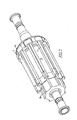
この問題を克服するために、ステージは、1つの軸端がロータと実質的に同一な構成を有する一時的なロータ固定具30に最初に組み付けられる。一時的なロータ固定具は、ロータ10の軸端でベアリング12を越えて滑り、リブの端部に近接する。ロータ固定具は、ロータ固定具上のリブ31がリブ11とともにロータ上で整列するように回転される。
To overcome this problem, the stage is first assembled to a
磁石キャリア18は、ロータ固定具上を滑り、かつ、ロータ固定具上のリブの突出部分に係合する各磁石キャリアの1つの縁部とともに軸方向に配置される。C型積層スタック17は、その後、磁石キャリアに保持されるC型積層スタックに接触して配置される。図1は、ロータ固定具上で組み込まれた列を示す。
The
分割圧縮リング40は、その後、図2及び図6に示すように、組み立てられた列を覆って固定される。ねじ41は、その後、ステージを圧縮するように回転させられ、そして、ロータ固定具上のリブのオーバーハングした表面から圧力を取り除く。全体のステージは、その後、図3に示すように、ロータを覆って軸方向の所定位置に移動する。
The
分割圧縮リング40は、クランプを構成する。クランプは、リブのオーバーハングした表面から離れて、ステージの要素を押すような圧力を及ぼすように作られる。要素のクリアランスは、要素がシャフトの中心に向かって内方に押されたときに、要素がシャフトに沿って滑るための許容可能なクリアランスを有するように配置される。
The
ステージが所定位置にきた後、分割圧縮リング40は、列の要素が最終の組み込み位置に広がることを許容するように取り除かれる。このプロセスは、その後、追加の列をロータ上の所定位置に配置するために繰り返される。
After the stage is in place, the
図4を参照すると、ロータ固定具は、より詳細に示される。1つの軸端で、固定具は、ロータのリブに対応するリブを有する。ロータ固定具は、非磁性材料で構成される。 Referring to FIG. 4, the rotor fixture is shown in more detail. At one shaft end, the fixture has ribs that correspond to the ribs of the rotor. The rotor fixture is made of a nonmagnetic material.
図5を参照すると、分割圧縮リング40は、300番代のステンレス鋼のような非磁性材料で構成される。調節ねじ41は、所定位置できつく締められたときに内径に従うように、圧縮リングの内径に近い端部で、スイベルヘッドを有する。それ故、圧力は、ステージの各要素に個別に作用する。これは、各要素に放射状に配列される調整ねじによって達成される。望ましくは、分割圧縮リング又はクランプがステージの要素を傷つけないように、テフロンのような軟質材料のスリーブがクランプとロータ要素との間に備えられる。
Referring to FIG. 5, the
特許法によって求められる特異性ともに詳細に既述された本発明について、特許証によって保護されるべきものが、特許請求の範囲において説明される。 What is to be protected by a patent certificate for the present invention, which has been described in detail in terms of the specificity required by the patent law, is set forth in the appended claims.
Claims (2)
a)固定具を、ロータの小径ベアリング部を越えて配置し、中央部の一端部に接近させること、中央部に近接する固定具の軸端がリブとオーバーハングスロットを含む中央部に適合する構成を有すること、
b)一列に組み立てるために、磁石キャリア内の磁石とC型積層スタックとを、固定具のリブを越えて滑らせること、
c)分割圧縮リングを、リブに組み付けられるC型積層スタックの外径を覆って配置すること、及び、C型積層スタックとオーバーハングスロットとの間にライディングクリアランスを与えるべく、C型積層スタックを十分に圧縮するように分割圧縮リングを接合すること、
d)圧縮リングと、磁石キャリア内の、組み立てられた磁石の列と、C型積層スタックとをロータ上で滑らせること、
e)ロータ上の所定位置で、磁石キャリア内の磁石の列とC型積層スタックとを残して圧縮リングを取り除くこと、
をさらに含む永久磁石を組み立てる方法。 A method of assembling a permanent magnet rotor, wherein the rotor includes a cylindrical shaft having a large diameter central shaft portion and two small diameter bearing portions, the central portion defining an even number of ribs with overhang slots. Part
a) The fixing tool is disposed beyond the small-diameter bearing portion of the rotor and is brought close to one end portion of the central portion. Having a configuration,
b) sliding the magnets in the magnet carrier and the C-type stack over the ribs of the fixture for assembly in a row;
c) The split compression ring is placed over the outer diameter of the C stack stacked on the rib, and the C stack is provided to provide a riding clearance between the C stack and the overhang slot. Joining the split compression ring to compress sufficiently,
d) sliding the compression ring, the assembled row of magnets in the magnet carrier, and the C-type stack on the rotor;
e) removing the compression ring in place on the rotor, leaving the row of magnets in the magnet carrier and the C-type stack;
A method of assembling a permanent magnet further comprising:
Applications Claiming Priority (2)
| Application Number | Priority Date | Filing Date | Title |
|---|---|---|---|
| US11/545,320 US7661185B2 (en) | 2006-10-10 | 2006-10-10 | Method for assembling rotor of permanent magnet motor |
| PCT/US2007/080790 WO2008045862A1 (en) | 2006-10-10 | 2007-10-09 | Method and apparatus for assembling rotor of permanent magnet motor |
Publications (2)
| Publication Number | Publication Date |
|---|---|
| JP2010506560A true JP2010506560A (en) | 2010-02-25 |
| JP2010506560A5 JP2010506560A5 (en) | 2010-10-14 |
Family
ID=38980935
Family Applications (1)
| Application Number | Title | Priority Date | Filing Date |
|---|---|---|---|
| JP2009532531A Withdrawn JP2010506560A (en) | 2006-10-10 | 2007-10-09 | Method and apparatus for assembling a rotor of a permanent magnet motor |
Country Status (5)
| Country | Link |
|---|---|
| US (2) | US7661185B2 (en) |
| EP (1) | EP2074688A1 (en) |
| JP (1) | JP2010506560A (en) |
| CA (1) | CA2664945A1 (en) |
| WO (1) | WO2008045862A1 (en) |
Cited By (1)
| Publication number | Priority date | Publication date | Assignee | Title |
|---|---|---|---|---|
| US9667111B2 (en) | 2013-06-20 | 2017-05-30 | Samsung Electronics Co., Ltd. | Rotor of electric motor and motor using the same |
Families Citing this family (10)
| Publication number | Priority date | Publication date | Assignee | Title |
|---|---|---|---|---|
| JP5362399B2 (en) * | 2009-03-13 | 2013-12-11 | 本田技研工業株式会社 | Rotating electric machine and method of manufacturing rotating electric machine |
| US8018110B2 (en) * | 2009-04-30 | 2011-09-13 | General Electric Company | High speed internal permanent magnet machine and method of manufacturing the same |
| US20130249345A1 (en) * | 2012-03-22 | 2013-09-26 | GM Global Technology Operations LLC | Segmented rotor in a rotor assembly |
| CN104953780A (en) | 2012-08-03 | 2015-09-30 | 埃塞克科技有限公司 | Modular rotatable transverse flux electrical machine |
| CA2827657A1 (en) | 2012-09-24 | 2014-03-24 | Eocycle Technologies Inc. | Modular transverse flux electrical machine |
| CA2829812A1 (en) | 2012-10-17 | 2014-04-17 | Eocycle Technologies Inc. | Transverse flux electrical machine rotor |
| CN105099027B (en) * | 2014-05-22 | 2018-02-09 | 台达电子工业股份有限公司 | Motor rotor and its locating ring |
| CN107370310A (en) * | 2017-09-18 | 2017-11-21 | 陈海兴 | A kind of rotor fills magnet apparatus |
| CN108336839B (en) | 2018-01-26 | 2019-08-02 | 北京金风科创风电设备有限公司 | Rotor, motor, reinforcing ring tool and mounting method thereof |
| CN110556984B (en) * | 2018-05-30 | 2021-07-02 | 上海电气集团上海电机厂有限公司 | Assembling method of magnetic steel with dovetail structure |
Family Cites Families (19)
| Publication number | Priority date | Publication date | Assignee | Title |
|---|---|---|---|---|
| US3818586A (en) | 1971-09-16 | 1974-06-25 | Briggs & Stratton Corp | Method of making an assembly of alternator magnet blocks with engine flywheel |
| US4117360A (en) * | 1977-04-15 | 1978-09-26 | General Electric Company | Self-supporting amortisseur cage for high-speed synchronous machine solid rotor |
| JPS5941294B2 (en) * | 1981-12-21 | 1984-10-05 | 住友特殊金属株式会社 | Magnetization assembly method of magnetic circuit |
| US5563463A (en) * | 1988-06-08 | 1996-10-08 | General Electric Company | Permanent magnet rotor |
| US5040286A (en) * | 1988-06-08 | 1991-08-20 | General Electric Company | Method for making permanent magnet rotor |
| JPH04185246A (en) * | 1990-11-20 | 1992-07-02 | Aisin Aw Co Ltd | Rotor for revolving-field type motor |
| JP2695332B2 (en) * | 1991-11-26 | 1997-12-24 | 三菱電機株式会社 | Permanent magnet field type rotor |
| FR2685571A1 (en) * | 1991-12-20 | 1993-06-25 | Valeo Systemes Dessuyage | ROTOR WITH PERMANENT MAGNETS, AND MAGNETO-DYNAMIC MACHINE, LIKE AN ENGINE WITHOUT MANIFOLD, EQUIPPED WITH SUCH A ROTOR. |
| US5881448A (en) * | 1992-04-06 | 1999-03-16 | General Electric Company | Method for making permanent magnet rotor |
| US6348752B1 (en) * | 1992-04-06 | 2002-02-19 | General Electric Company | Integral motor and control |
| DE4401241C2 (en) * | 1994-01-18 | 1997-09-25 | Richter Chemie Technik Gmbh | Magnetic attachment in magnetic couplings |
| US5687471A (en) * | 1994-06-14 | 1997-11-18 | Honda Giken Kogyo Kabushiki Kaisha | Method of and apparatus for covering rotor magnets |
| CA2203055C (en) * | 1996-04-19 | 1999-12-14 | Kenji Morii | Method of and apparatus for covering permanent magnets on motor rotor with cylindrical sleeve |
| US7205695B2 (en) | 1998-04-21 | 2007-04-17 | Drs Power & Control Technologies, Inc. | High speed rotor |
| US6552459B2 (en) * | 2001-03-20 | 2003-04-22 | Emerson Electric Co. | Permanent magnet rotor design |
| JP2004270544A (en) * | 2003-03-07 | 2004-09-30 | Matsushita Electric Ind Co Ltd | Magnetization jig, electric compressor, assembling method of rotor, and assembling method of electric compressor |
| DE112004000178B4 (en) * | 2003-09-04 | 2017-08-10 | Mitsubishi Denki K.K. | Permanent magnet synchronous motor and method for its production |
| US6933645B1 (en) * | 2004-04-05 | 2005-08-23 | Elliott Company | Permanent magnet rotor and magnet cradle |
| DE102004047311A1 (en) * | 2004-09-29 | 2006-04-13 | Minebea Co., Ltd. | Rotor body for a rotor of an electric machine and method for producing a rotor body |
-
2006
- 2006-10-10 US US11/545,320 patent/US7661185B2/en active Active
-
2007
- 2007-10-09 CA CA002664945A patent/CA2664945A1/en not_active Abandoned
- 2007-10-09 JP JP2009532531A patent/JP2010506560A/en not_active Withdrawn
- 2007-10-09 EP EP07853860A patent/EP2074688A1/en not_active Withdrawn
- 2007-10-09 WO PCT/US2007/080790 patent/WO2008045862A1/en active Application Filing
-
2009
- 2009-12-28 US US12/647,970 patent/US7854059B2/en active Active
Cited By (1)
| Publication number | Priority date | Publication date | Assignee | Title |
|---|---|---|---|---|
| US9667111B2 (en) | 2013-06-20 | 2017-05-30 | Samsung Electronics Co., Ltd. | Rotor of electric motor and motor using the same |
Also Published As
| Publication number | Publication date |
|---|---|
| US20080083112A1 (en) | 2008-04-10 |
| CA2664945A1 (en) | 2008-04-17 |
| US20100101080A1 (en) | 2010-04-29 |
| US7661185B2 (en) | 2010-02-16 |
| WO2008045862A1 (en) | 2008-04-17 |
| EP2074688A1 (en) | 2009-07-01 |
| US7854059B2 (en) | 2010-12-21 |
Similar Documents
| Publication | Publication Date | Title |
|---|---|---|
| JP2010506560A (en) | Method and apparatus for assembling a rotor of a permanent magnet motor | |
| US10355544B2 (en) | Rotor member fixed to rotary shaft of electrical rotating machine, rotor, rotary electric machine and method for disassembling rotor | |
| US4918802A (en) | Method and apparatus for making permanent magnet rotors | |
| AU2006264181B2 (en) | Transverse flux electrical machine with segmented core stator | |
| US20130207507A1 (en) | Rotor assembly for motor and manufacturing method thereof | |
| EP0718959A2 (en) | Rotor assembly for hybrid alternator | |
| JP2003088017A5 (en) | ||
| JP4209627B2 (en) | Permanent magnet electric machine | |
| JP2009148035A (en) | Rotor attaching apparatus | |
| US7812495B2 (en) | Sleeve in end rings for permanent magnet rotor | |
| JP2010506560A5 (en) | ||
| US11791682B2 (en) | Radial multi piece rotor for electric machine | |
| JP2008289329A (en) | End plate of motor | |
| US20110304233A1 (en) | Electric machine having a rotor | |
| EP2267868A2 (en) | Rotor for permanent magnet electric machine | |
| CN108696019B (en) | End plate for rotor of switched reluctance motor | |
| EP3793065A1 (en) | Rotor for an axial-flux electric machine, and axial-flux electric machine provided with said rotor | |
| JP2005312153A (en) | Permanent magnet type rotor and its manufacturing method | |
| US20180287443A1 (en) | Rotating electric machine | |
| JP6593881B2 (en) | Manufacturing method of axial gap type rotating electrical machine | |
| JPH01274653A (en) | Inrevolvable rotor | |
| WO2018100728A1 (en) | Outer rotor-type dynamo-electric machine and elevator hoist | |
| EP1630932A1 (en) | Spacers for axial spacing enclosure rings and shields for rotor of an electrical machine | |
| JP2004215445A (en) | Method and apparatus for manufacturing stator | |
| JP6361242B2 (en) | Rotor and rotor manufacturing method |
Legal Events
| Date | Code | Title | Description |
|---|---|---|---|
| A521 | Request for written amendment filed |
Free format text: JAPANESE INTERMEDIATE CODE: A523 Effective date: 20100825 |
|
| A621 | Written request for application examination |
Free format text: JAPANESE INTERMEDIATE CODE: A621 Effective date: 20100825 |
|
| A761 | Written withdrawal of application |
Free format text: JAPANESE INTERMEDIATE CODE: A761 Effective date: 20111207 |
|
| A521 | Request for written amendment filed |
Free format text: JAPANESE INTERMEDIATE CODE: A821 Effective date: 20111207 |