JP2010504820A - Apparatus and method for repairing a thoracic aortic aneurysm - Google Patents
Apparatus and method for repairing a thoracic aortic aneurysm Download PDFInfo
- Publication number
- JP2010504820A JP2010504820A JP2009530428A JP2009530428A JP2010504820A JP 2010504820 A JP2010504820 A JP 2010504820A JP 2009530428 A JP2009530428 A JP 2009530428A JP 2009530428 A JP2009530428 A JP 2009530428A JP 2010504820 A JP2010504820 A JP 2010504820A
- Authority
- JP
- Japan
- Prior art keywords
- stent
- graft
- support
- sheath
- delivery
- Prior art date
- Legal status (The legal status is an assumption and is not a legal conclusion. Google has not performed a legal analysis and makes no representation as to the accuracy of the status listed.)
- Pending
Links
Images


Classifications
-
- A—HUMAN NECESSITIES
- A61—MEDICAL OR VETERINARY SCIENCE; HYGIENE
- A61F—FILTERS IMPLANTABLE INTO BLOOD VESSELS; PROSTHESES; DEVICES PROVIDING PATENCY TO, OR PREVENTING COLLAPSING OF, TUBULAR STRUCTURES OF THE BODY, e.g. STENTS; ORTHOPAEDIC, NURSING OR CONTRACEPTIVE DEVICES; FOMENTATION; TREATMENT OR PROTECTION OF EYES OR EARS; BANDAGES, DRESSINGS OR ABSORBENT PADS; FIRST-AID KITS
- A61F2/00—Filters implantable into blood vessels; Prostheses, i.e. artificial substitutes or replacements for parts of the body; Appliances for connecting them with the body; Devices providing patency to, or preventing collapsing of, tubular structures of the body, e.g. stents
- A61F2/02—Prostheses implantable into the body
- A61F2/04—Hollow or tubular parts of organs, e.g. bladders, tracheae, bronchi or bile ducts
- A61F2/06—Blood vessels
- A61F2/07—Stent-grafts
-
- A—HUMAN NECESSITIES
- A61—MEDICAL OR VETERINARY SCIENCE; HYGIENE
- A61F—FILTERS IMPLANTABLE INTO BLOOD VESSELS; PROSTHESES; DEVICES PROVIDING PATENCY TO, OR PREVENTING COLLAPSING OF, TUBULAR STRUCTURES OF THE BODY, e.g. STENTS; ORTHOPAEDIC, NURSING OR CONTRACEPTIVE DEVICES; FOMENTATION; TREATMENT OR PROTECTION OF EYES OR EARS; BANDAGES, DRESSINGS OR ABSORBENT PADS; FIRST-AID KITS
- A61F2/00—Filters implantable into blood vessels; Prostheses, i.e. artificial substitutes or replacements for parts of the body; Appliances for connecting them with the body; Devices providing patency to, or preventing collapsing of, tubular structures of the body, e.g. stents
- A61F2/95—Instruments specially adapted for placement or removal of stents or stent-grafts
- A61F2/9517—Instruments specially adapted for placement or removal of stents or stent-grafts handle assemblies therefor
-
- A—HUMAN NECESSITIES
- A61—MEDICAL OR VETERINARY SCIENCE; HYGIENE
- A61F—FILTERS IMPLANTABLE INTO BLOOD VESSELS; PROSTHESES; DEVICES PROVIDING PATENCY TO, OR PREVENTING COLLAPSING OF, TUBULAR STRUCTURES OF THE BODY, e.g. STENTS; ORTHOPAEDIC, NURSING OR CONTRACEPTIVE DEVICES; FOMENTATION; TREATMENT OR PROTECTION OF EYES OR EARS; BANDAGES, DRESSINGS OR ABSORBENT PADS; FIRST-AID KITS
- A61F2/00—Filters implantable into blood vessels; Prostheses, i.e. artificial substitutes or replacements for parts of the body; Appliances for connecting them with the body; Devices providing patency to, or preventing collapsing of, tubular structures of the body, e.g. stents
- A61F2/82—Devices providing patency to, or preventing collapsing of, tubular structures of the body, e.g. stents
- A61F2/86—Stents in a form characterised by the wire-like elements; Stents in the form characterised by a net-like or mesh-like structure
- A61F2/89—Stents in a form characterised by the wire-like elements; Stents in the form characterised by a net-like or mesh-like structure the wire-like elements comprising two or more adjacent rings flexibly connected by separate members
-
- A—HUMAN NECESSITIES
- A61—MEDICAL OR VETERINARY SCIENCE; HYGIENE
- A61F—FILTERS IMPLANTABLE INTO BLOOD VESSELS; PROSTHESES; DEVICES PROVIDING PATENCY TO, OR PREVENTING COLLAPSING OF, TUBULAR STRUCTURES OF THE BODY, e.g. STENTS; ORTHOPAEDIC, NURSING OR CONTRACEPTIVE DEVICES; FOMENTATION; TREATMENT OR PROTECTION OF EYES OR EARS; BANDAGES, DRESSINGS OR ABSORBENT PADS; FIRST-AID KITS
- A61F2/00—Filters implantable into blood vessels; Prostheses, i.e. artificial substitutes or replacements for parts of the body; Appliances for connecting them with the body; Devices providing patency to, or preventing collapsing of, tubular structures of the body, e.g. stents
- A61F2/82—Devices providing patency to, or preventing collapsing of, tubular structures of the body, e.g. stents
- A61F2/86—Stents in a form characterised by the wire-like elements; Stents in the form characterised by a net-like or mesh-like structure
- A61F2/90—Stents in a form characterised by the wire-like elements; Stents in the form characterised by a net-like or mesh-like structure characterised by a net-like or mesh-like structure
-
- A—HUMAN NECESSITIES
- A61—MEDICAL OR VETERINARY SCIENCE; HYGIENE
- A61F—FILTERS IMPLANTABLE INTO BLOOD VESSELS; PROSTHESES; DEVICES PROVIDING PATENCY TO, OR PREVENTING COLLAPSING OF, TUBULAR STRUCTURES OF THE BODY, e.g. STENTS; ORTHOPAEDIC, NURSING OR CONTRACEPTIVE DEVICES; FOMENTATION; TREATMENT OR PROTECTION OF EYES OR EARS; BANDAGES, DRESSINGS OR ABSORBENT PADS; FIRST-AID KITS
- A61F2/00—Filters implantable into blood vessels; Prostheses, i.e. artificial substitutes or replacements for parts of the body; Appliances for connecting them with the body; Devices providing patency to, or preventing collapsing of, tubular structures of the body, e.g. stents
- A61F2/02—Prostheses implantable into the body
- A61F2/04—Hollow or tubular parts of organs, e.g. bladders, tracheae, bronchi or bile ducts
- A61F2/06—Blood vessels
- A61F2/07—Stent-grafts
- A61F2002/075—Stent-grafts the stent being loosely attached to the graft material, e.g. by stitching
-
- A—HUMAN NECESSITIES
- A61—MEDICAL OR VETERINARY SCIENCE; HYGIENE
- A61F—FILTERS IMPLANTABLE INTO BLOOD VESSELS; PROSTHESES; DEVICES PROVIDING PATENCY TO, OR PREVENTING COLLAPSING OF, TUBULAR STRUCTURES OF THE BODY, e.g. STENTS; ORTHOPAEDIC, NURSING OR CONTRACEPTIVE DEVICES; FOMENTATION; TREATMENT OR PROTECTION OF EYES OR EARS; BANDAGES, DRESSINGS OR ABSORBENT PADS; FIRST-AID KITS
- A61F2/00—Filters implantable into blood vessels; Prostheses, i.e. artificial substitutes or replacements for parts of the body; Appliances for connecting them with the body; Devices providing patency to, or preventing collapsing of, tubular structures of the body, e.g. stents
- A61F2/95—Instruments specially adapted for placement or removal of stents or stent-grafts
- A61F2002/9505—Instruments specially adapted for placement or removal of stents or stent-grafts having retaining means other than an outer sleeve, e.g. male-female connector between stent and instrument
- A61F2002/9511—Instruments specially adapted for placement or removal of stents or stent-grafts having retaining means other than an outer sleeve, e.g. male-female connector between stent and instrument the retaining means being filaments or wires
-
- A—HUMAN NECESSITIES
- A61—MEDICAL OR VETERINARY SCIENCE; HYGIENE
- A61F—FILTERS IMPLANTABLE INTO BLOOD VESSELS; PROSTHESES; DEVICES PROVIDING PATENCY TO, OR PREVENTING COLLAPSING OF, TUBULAR STRUCTURES OF THE BODY, e.g. STENTS; ORTHOPAEDIC, NURSING OR CONTRACEPTIVE DEVICES; FOMENTATION; TREATMENT OR PROTECTION OF EYES OR EARS; BANDAGES, DRESSINGS OR ABSORBENT PADS; FIRST-AID KITS
- A61F2/00—Filters implantable into blood vessels; Prostheses, i.e. artificial substitutes or replacements for parts of the body; Appliances for connecting them with the body; Devices providing patency to, or preventing collapsing of, tubular structures of the body, e.g. stents
- A61F2/95—Instruments specially adapted for placement or removal of stents or stent-grafts
- A61F2/962—Instruments specially adapted for placement or removal of stents or stent-grafts having an outer sleeve
- A61F2/966—Instruments specially adapted for placement or removal of stents or stent-grafts having an outer sleeve with relative longitudinal movement between outer sleeve and prosthesis, e.g. using a push rod
- A61F2002/9665—Instruments specially adapted for placement or removal of stents or stent-grafts having an outer sleeve with relative longitudinal movement between outer sleeve and prosthesis, e.g. using a push rod with additional retaining means
Abstract
Description
技術分野
本発明は、胸部大動脈瘤の修復のための装置および方法に関連する。
TECHNICAL FIELD The present invention relates to devices and methods for the repair of thoracic aortic aneurysms.
本発明の背景
従来における拡張可能な血管内プロテーゼインプラント(例えばステントおよびステントグラフトなど)については、患者の血管システム内における損傷部位に挿入および留置するために、カテーテル内に装着することが可能である。このカテーテルは、一般的には、損傷部位への搬送中、挿入構造内にプロテーゼインプラント(prosthetic implant)を保持するように構成されている。損傷部位では、例えば、プロテーゼインプラントの近接端部(患者の熱の位置に対しての)からその遠位端部まで、カテーテルシースを引き抜くことによって、プロテーゼインプラントを留置することが可能である。
BACKGROUND OF THE INVENTION Conventional expandable endovascular prosthetic implants (eg, stents and stent grafts) can be installed in a catheter for insertion and placement at a site of injury within a patient's vascular system. The catheter is generally configured to hold a prosthetic implant within the insertion structure during delivery to the injury site. At the injury site, the prosthetic implant can be placed, for example, by withdrawing the catheter sheath from the proximal end of the prosthetic implant (relative to the patient's thermal location) to its distal end.
プロテーゼインプラントは、血管内の処置あるいは治療中に、ターゲットの損傷部位を十分にカバーするように、正確に配置されなければならない。多くの従来のカテーテルを用いる場合、カテーテルシースがインプラントの周囲から引き抜かれる際に、カテーテルシースとの摩擦による干渉あるいは接触によって、留置中にインプラントが動いてしまう可能性がある。このようなインプラントの動きについての懸念は、網状のステントのような高い縮小率(foreshortening percentage)を有しているインプラントを留置する場合に増加する。例えば、20パーセントの縮小率を有する網状のステントを留置する場合には、ステントにおける近接端部と反対側の遠位端部とが、互いにくっついてしまう傾向がある。これは、ステントを、ターゲットである損傷部位内における所望の固着位置からずらしてしまう。さらに、不正確なインプラント配置によって、健康な血管および/または血管枝といった、所望しない位置をカバーしてしまうと、血管枝の閉塞および/または再狭窄などの、好ましくない臨床的結果を招来する可能性がある。留置中における所望しないインプラントの動きを防止あるいは制限しようとして失敗した試みのなかには、インプラントとカテーテルシースとの間における摩擦による接触を減少するために、滑らかなコーティングを従来のインプラントに塗布する、というのもある。 Prosthetic implants must be accurately positioned to sufficiently cover the target injury site during endovascular treatment or therapy. With many conventional catheters, when the catheter sheath is withdrawn from around the implant, the implant may move during placement due to frictional interference or contact with the catheter sheath. Concern about the movement of such implants is increased when implants with high forcing percentage, such as reticulated stents, are deployed. For example, when a reticulated stent having a reduction rate of 20 percent is placed, the proximal end and the opposite distal end of the stent tend to stick to each other. This shifts the stent from the desired anchoring location within the targeted lesion site. In addition, inaccurate implant placement that covers undesired locations, such as healthy blood vessels and / or branch vessels, can lead to undesirable clinical results such as occlusion and / or restenosis of vessel branches. There is sex. One unsuccessful attempt to prevent or limit unwanted implant movement during placement is to apply a smooth coating to conventional implants to reduce frictional contact between the implant and the catheter sheath. There is also.
プロテーゼインプラントの設置に伴ういくつかの追加的な合併症は、胸部および腹部大動脈瘤治療などの、従来における特定の血管内治療に関連している。例えば、胸部のステントグラフトの設置に関連する1つの現象は、「吹き流し(wind sock)」効果である。胸部領域における高い血流速度、体積勾配および/または圧力勾配に起因して、ステントグラフトにおける初めての留置中に、胸部領域における血流および/または圧力勾配の結果として、ステントグラフトの近接端部を、好ましくないことに、遠位に押すあるいは移動してしまう可能性がある。このような移動は、損傷部位に対するステントグラフトの不正確な位置調整を招来する可能性がある。さらに、腹部大動脈瘤の治療において、腎動脈の端部と動脈瘤の端部との間における、不十分な距離(一般的に、「短頸(short neck)」と称されている)が、血管内処置あるいは治療における患者の受容を、阻止あるいは制限する可能性がある。 Some additional complications associated with the placement of prosthetic implants are associated with certain conventional endovascular treatments, such as the treatment of thoracic and abdominal aortic aneurysms. For example, one phenomenon associated with placement of a chest stent graft is the “wind sock” effect. Due to the high blood flow velocity, volume gradient and / or pressure gradient in the thoracic region, during the first placement in the stent graft, the proximal end of the stent graft is preferred as a result of blood flow and / or pressure gradient in the thoracic region. Not being able to push or move distally. Such movement can lead to inaccurate positioning of the stent graft relative to the injury site. In addition, in the treatment of abdominal aortic aneurysms, an insufficient distance between the end of the renal artery and the end of the aneurysm (commonly referred to as “short neck”), It may prevent or limit patient acceptance in endovascular treatment or therapy.
血管の湾曲部分に自己展開式のステントグラフトが留置された場合、ステントグラフトは、血管の湾曲に対応および/または適合する必要がある。従来のステントグラフトは、血管の湾曲に近づけるために、互いに重なり合っている不連続性のあるいは非隣接性の複
数のステント素子を含んでいる。従来のステントグラフトにおける前記のような素子の重なり合いは、ステントグラフトにおける角状変形を引き起こす可能性があり、および/または、血流および/または圧力の変化によって引き起こされる個々の拍動運動による、ステントグラフトあるいは血管における構造的なダメージの発生確率を、増加させる可能性がある。ステント素子を重ね合わせることによって形成された従来のステントグラフトは、また、このステントグラフトを血管の湾曲に近づけたときに、このステントグラフトにおける所望しない捩れあるいは屈曲をもたらすこともある。これは、ステントグラフト内の血流を危うくしてしまう。血管の湾曲に近づくように屈曲あるいはさもなければ湾曲されている他の従来のステントグラフトは、血管壁から離れてしまう可能性がある。なぜならば、このような従来のステントグラフトは、湾曲した血管部分に対してスムーズに適合しないからである。このような分離は、接続エンドリーク(attachment endoleak)、フラップ閉塞、および/または、ステントグラフトのグラフト部分および/または血管壁に対するステントグラフトの突出部分、を誘発する可能性があり、これらは、ダメージおよび/または負傷を引き起こす。
If a self-expanding stent graft is placed in a curved portion of a blood vessel, the stent graft needs to accommodate and / or conform to the blood vessel curvature. Conventional stent grafts include a plurality of discontinuous or non-adjacent stent elements that overlap each other to approximate the curvature of the blood vessel. Overlapping of such elements in conventional stent grafts can cause angular deformation in the stent graft and / or stent graft or vessel due to individual pulsatile movement caused by changes in blood flow and / or pressure. There is a possibility of increasing the probability of occurrence of structural damage. Conventional stent grafts formed by overlapping stent elements may also cause undesired twisting or bending in the stent graft when the stent graft is brought close to the curvature of the blood vessel. This compromises blood flow within the stent graft. Other conventional stent grafts that are bent or otherwise curved to approximate the curvature of the vessel can leave the vessel wall. This is because such conventional stent grafts do not fit smoothly into curved vessel segments. Such segregation can induce attachment endoleaks, flap occlusions, and / or stent graft graft portions and / or protruding portions of the stent graft relative to the vessel wall, which can cause damage and / or Or cause injury.
発明の概要
本発明は、改善されたステントグラフト、改善されたステントグラフトの搬送システム、および、ステントグラフトを搬送するための改善された方法を提供しようと努めている。
SUMMARY OF THE INVENTION The present invention seeks to provide an improved stent graft, an improved stent graft delivery system, and an improved method for delivering a stent graft.
本発明における1つの態様にしたがうと、体内の管の内部に留置するためのステントグラフトにおいて、
近接端部および遠位端部を備えたチューブ状のグラフトと、
少なくとも一部がチューブ状のグラフト内に位置しており、近接端部および遠位端部を備えたサポートステントと、を含んでおり、
サポートステントが、少なくとも1本のワイヤーを含んでおり、このワイヤーが、サポートステントの軸に関する第1の並進運動方向を有する第1のらせん形のワイヤー部分と、この第1の並進運動方向とは逆向きの、前記の軸に関する第2の並進運動方向を有する第2のらせん形のワイヤー部分と、を形成しており、
サポートステントが平らにされた搬送構造にあるときに、このサポートステントが、第1の長さを有しており、さらに、サポートステントが拡張された留置構造にあるときに、このサポートステントが、第1の長さよりも短い第2の長さを有しており、
搬送構造にあるときに、サポートステントが、グラフトの近接端部のみあるいはその近傍において、グラフトに接続されているステントグラフト、が提供される。
According to one aspect of the present invention, in a stent graft for placement within a body vessel,
A tubular graft with a proximal end and a distal end;
A support stent having at least a portion located within the tubular graft and having a proximal end and a distal end;
The support stent includes at least one wire, the wire having a first helical wire portion having a first translational direction relative to the axis of the support stent, and the first translational direction. Forming a second helical wire portion having a second direction of translation with respect to said axis in an opposite direction,
The support stent has a first length when the support stent is in a flattened delivery structure, and further when the support stent is in an expanded indwelling structure, the support stent is Having a second length shorter than the first length;
When in the delivery structure, a stent graft is provided in which the support stent is connected to the graft only at or near the proximal end of the graft.
本発明における他の態様にしたがうと、ステントグラフトにおいて、
近接端部および遠位端部を備えたチューブ状のグラフトと、
少なくとも一部がチューブ状のグラフト内に位置しており、近接端部および遠位端部を備えたサポートステントと、を含んでおり、
サポートステントが平らにされた搬送構造にあるときに、このサポートステントの近接端部が、グラフトの近接端部のみに結合されており、
グラフトの遠位端部においてグラフトに接続された固定メカニズムであって、拡張された留置構造にあるサポートステントを係合するとともに、この留置構造にあるサポートステントの直径および長さを実質的に固定するように構成された少なくとも1つの係合部材を備えた、固定メカニズムと、
サポートステントの近接端部に対して動作可能に結合された捕獲メカニズムであって、サポートステントの近接端部を搬送構造に維持するように構成可能構成可能であるととも
に、サポートステントの近接端部を解放するように作動することが可能である、捕獲メカニズムと、をさらに含んでいるステントグラフト、が提供される。
According to another aspect of the invention, in a stent graft,
A tubular graft with a proximal end and a distal end;
A support stent having at least a portion located within the tubular graft and having a proximal end and a distal end;
When the support stent is in a flattened delivery structure, the proximal end of the support stent is bonded only to the proximal end of the graft,
A fixation mechanism connected to the graft at the distal end of the graft for engaging the support stent in the expanded indwelling structure and substantially fixing the diameter and length of the support stent in the indwelling structure A locking mechanism comprising at least one engagement member configured to:
A capture mechanism operatively coupled to the proximal end of the support stent, configurable to maintain the proximal end of the support stent in a delivery structure, and the proximal end of the support stent A stent graft further including a capture mechanism that is operable to release is provided.
本発明における他の態様にしたがうと、体内の管内にステントグラフトを留置するための、搬送システムが提供される。このステントグラフトは、
近接端部と遠位端部とを備えており、平らにされた搬送構造から拡張構造に拡張可能なサポートステントと、
近接端部と遠位端部とを備えており、平らにされた搬送構造から留置構造に留置可能なアンカーステントと、
近接端部と遠位端部とを備えたチューブ状のグラフトであって、このグラフトの近接端部が、アンカーステントに結合されており、アンカーステントとともに平らにされた搬送構造から留置構造に留置可能となっている、チューブ状のグラフトと、を含んでおり、
この搬送システムが、
ワイヤールーメンであって、その周囲にサポートステントをスライド可能に配置することの可能なワイヤールーメンと、
サポートステントが搬送構造にある場合に、このサポートステントの周囲に、引き抜き可能に配置可能な内部シースと、
平らにされた搬送構造にあるグラフトおよびアンカーステントの周囲に、引き抜き可能に配置されている外部シースと、を含んでいる。
In accordance with another aspect of the present invention, a delivery system is provided for placing a stent graft in a body vessel. This stent graft
A support stent having a proximal end and a distal end and expandable from a flattened delivery structure to an expanded structure;
An anchor stent having a proximal end and a distal end, the anchor stent being deployable from the flattened delivery structure to the deployment structure;
A tubular graft having a proximal end and a distal end, wherein the proximal end of the graft is coupled to an anchor stent and is placed in the deployment structure from a delivery structure flattened with the anchor stent. A tube-shaped graft,
This transport system
A wire lumen capable of slidably placing a support stent around the wire lumen;
When the support stent is in the delivery structure, an inner sheath that can be removably disposed around the support stent;
And an outer sheath that is removably disposed about the graft and anchor stent around the flattened delivery structure.
本発明における他の態様にしたがうと、体内の管内にステントグラフトを留置するための搬送システムにおいて、このステントグラフトが、
近接端部と遠位端部とを備えており、平らにされた搬送構造から拡張構造に拡張可能なサポートステントと、
近接端部と遠位端部とを備えており、平らにされた搬送構造から留置構造に留置可能なアンカーステントと、を備えており、
この搬送システムが、
ガイドワイヤと、
このガイドワイヤの周囲にスライド可能に配置可能であるワイヤールーメンであって、その周囲にサポートステントをスライド可能に配置するワイヤールーメンと、
サポートステントが搬送構造にある場合に、このサポートステントの周囲に引き抜き可能に配置可能である内部シースであって、その周囲にアンカーステントをスライド可能に配置する内部シースと、
アンカーステントが挿入構造にある場合に、アンカーステントの周囲に、引き抜き可能に配置可能な外部シースと、
内部シースおよび外部シースのそれぞれに対して、動作可能に結合されているハンドルと、を有している搬送システム、が提供される。
According to another aspect of the present invention, in a delivery system for placing a stent graft within a body vessel, the stent graft comprises:
A support stent having a proximal end and a distal end and expandable from a flattened delivery structure to an expanded structure;
An anchor stent having a proximal end and a distal end, the anchor stent being deployable from the flattened delivery structure to the deployment structure;
This transport system
A guide wire;
A wire lumen that can be slidably disposed around the guide wire, the wire lumen having a support stent slidably disposed therearound;
An inner sheath that is slidably displaceable around the support stent when the support stent is in a delivery structure;
An outer sheath releasably displaceable around the anchor stent when the anchor stent is in the insertion configuration;
A delivery system is provided having a handle operably coupled to each of the inner and outer sheaths.
本発明は、さらに、ターゲット位置において体内ルーメン内に管腔内プロテーゼ(endoluminal prosthesis)を留置するための搬送システムにおいて、
近接端部および遠位端部を備えた搬送シースであって、搬送シースの遠位端部において、搬送システム内のプロテーゼを拡張されていない構造に維持するように構成されている搬送シースと、
少なくとも部分的に搬送シース内に配置された遠位端部と近接端部とを備えたサポート部材であって、このサポート部材の近接端部が、プロテーゼの遠位端部に隣接しているサポート部材と、
搬送シースおよびサポート部材の少なくとも1つに対して、相対運動を与えるように構成されているハンドルと、を含んでいる搬送システム、を提供する。
The present invention further provides a delivery system for indwelling an endoluminal prosthesis within a body lumen at a target location,
A delivery sheath having a proximal end and a distal end, wherein the delivery sheath is configured to maintain a prosthesis in the delivery system in an unexpanded configuration at the distal end of the delivery sheath;
A support member having a distal end and a proximal end disposed at least partially within the delivery sheath, wherein the proximal end of the support member is adjacent to the distal end of the prosthesis Members,
A delivery system is provided that includes a handle configured to provide relative movement with respect to at least one of the delivery sheath and the support member.
本発明は、さらに、搬送システムにおいて、
ガイドワイヤ通過域を提供するシャフトと、
このガイドワイヤ通過域内に配置されているガイドワイヤと、
シャフトに対して移動可能に結合されている遠位端部と近接端部とを備え、シャフトの軸に沿って、第1の方向に進むように構成されている、サポート部材と、
このサポート部材を少なくとも部分的に取り囲むように、および、第1の方向とは逆の第2の方向に引き抜かれるように構成されている、チューブ状の搬送シースと、を含んでいる搬送システム、を対象としている。
The present invention further provides a conveyance system comprising:
A shaft providing a guide wire passage area;
A guide wire disposed in the guide wire passage area;
A support member having a distal end and a proximal end movably coupled to the shaft and configured to travel in a first direction along an axis of the shaft;
A delivery system including a tubular delivery sheath configured to at least partially surround the support member and to be withdrawn in a second direction opposite to the first direction; Is targeted.
本発明における他の態様にしたがうと、体内の管内にステントグラフトを留置するための、ステントグラフトと搬送システムとのアセンブリにおいて、
ワイヤールーメンと、
このワイヤールーメンの周囲にスライド可能に配置されており、近接端部および遠位端部を含み、平らにされた搬送構造から拡張構造に拡張することの可能なサポートステントと、
サポートステントが搬送構造にある場合に、このサポートステントの周囲に、引き抜き可能に配置されている内部シースと、
この内部シースに対してスライド可能に配置されており、近接端部および遠位端部を含み、平らにされた搬送構造から留置構造に留置可能なアンカーステントと、
近接端部と遠位端部とを備えたチューブ状のグラフトであって、このグラフトの近接端部が、アンカーステントに結合されており、アンカーステントとともに平らにされた搬送構造から留置構造に留置可能となっている、チューブ状のグラフトと、
平らにされた搬送構造にあるグラフトおよびアンカーステントの周囲に、引き抜き可能に配置されている外部シースと、を含んでいるアセンブリ、が提供される。
In accordance with another aspect of the present invention, in an assembly of a stent graft and a delivery system for placing a stent graft in a vessel in the body,
Wire lumen,
A support stent that is slidably disposed about the wire lumen and includes a proximal end and a distal end and is expandable from a flattened delivery structure to an expanded structure;
When the support stent is in the delivery structure, an inner sheath that is detachably disposed around the support stent;
An anchor stent that is slidably disposed relative to the inner sheath and includes a proximal end and a distal end and is deployable from the flattened delivery structure to the deployment structure;
A tubular graft having a proximal end and a distal end, wherein the proximal end of the graft is coupled to an anchor stent and is placed in the deployment structure from a delivery structure flattened with the anchor stent. Tube grafts that are possible,
An assembly is provided that includes an outer sheath that is removably disposed about a graft and an anchor stent in a flattened delivery structure.
本発明における他の態様にしたがうと、体内の管内にステントグラフトを留置するための方法において、
ワイヤールーメンの周囲にスライド可能に配置されており、近接端部および遠位端部を有し、平らにされた搬送構造から拡張構造に拡張することの可能なサポートステントと、このサポートステントが搬送構造にある場合に、サポートステントの周囲に引き抜き可能に配置されている内部シースと、この内部シースの周囲にスライド可能に配置されており、平らにされた搬送構造から留置構造に留置可能なアンカーステントと、を備えている搬送デバイスを準備するステップと、
アンカーステントを搬送構造から拡張構造に拡張するために、外部シースを引き抜くステップと、
体内の管内にアンカーステントを留置するステップと、
サポートステントを平らにされた挿入構造から拡張構造に拡張するために、内部シースを引き抜くステップと、を含んでいる方法、が提供される。
According to another aspect of the invention, in a method for placing a stent graft in a vessel in a body,
A support stent that is slidably disposed about the wire lumen, has a proximal end and a distal end, and can be expanded from a flattened delivery structure to an expanded structure; An inner sheath that is removably disposed around the support stent, and an anchor that is slidably disposed about the inner sheath and can be placed in the indwelling structure from the flattened delivery structure when in the structure Providing a delivery device comprising a stent; and
Pulling the outer sheath to expand the anchor stent from the delivery structure to the expanded structure;
Placing an anchor stent in a tube in the body;
Withdrawing the inner sheath to expand the support stent from the flattened insertion structure to the expansion structure.
本発明における他の態様にしたがうと、ターゲット位置において、体内の管内にステントグラフトを留置するための方法において、
近接端部および遠位端部を有し、さらに、遠位端部において遠位リングを有するステントグラフトを準備するステップと、
ターゲット位置に向けてのステントグラフトの搬送中に、ステントグラフトを搬送構造に維持するように構成されており、内部シースおよび外部シースを有している搬送デバイスを準備するステップと、
ステントグラフトの遠位リングを、ターゲット位置に関して遠位の固着位置に配置するために、患者の心臓の位置に関して近位方向および遠位方向の一方に、搬送デバイスを移動するステップと、
ステントグラフトの遠位端部および遠位リングを留置するために、搬送デバイスの外部シースを撤去するステップと、
遠位位置において、遠位リングを血管壁に固着するステップと、
ステントグラフトの近接端部を留置するために、搬送デバイスの内部シースを撤去するステップと、
近接した固着位置において、ステントグラフトの近接端部を血管壁に固着するステップと、を含んでいる方法、が提供される。
In accordance with another aspect of the present invention, in a method for deploying a stent graft within a body vessel at a target location,
Providing a stent graft having a proximal end and a distal end, and further having a distal ring at the distal end;
Providing a delivery device configured to maintain the stent graft in a delivery structure during delivery of the stent graft toward a target location and having an inner sheath and an outer sheath;
Moving the delivery device in one of a proximal direction and a distal direction with respect to the position of the patient's heart to position the distal ring of the stent graft in a distal anchored position with respect to the target position;
Removing the outer sheath of the delivery device to deploy the distal end of the stent graft and the distal ring;
Securing the distal ring to the vessel wall at a distal position;
Removing the inner sheath of the delivery device to deploy the proximal end of the stent graft;
Anchoring the proximal end of the stent graft to the vessel wall at a proximal anchor location.
有利には、前記ステントグラフトは、チューブ状のグラフトと、このチューブ状のグラフト内に少なくとも部分的に配置されているサポートステントとを備えている。 Advantageously, the stent graft comprises a tubular graft and a support stent disposed at least partially within the tubular graft.
好ましくは、搬送構造において、サポートステントが、グラフトの近接端部のみに結合されている。 Preferably, in the delivery structure, the support stent is coupled only to the proximal end of the graft.
前記の方法は、さらに、サポートステントを留置構造に固定することを含むことが可能である。 The method can further include securing the support stent to the indwelling structure.
サポートステントを留置構造に固定するという追加的なステップは、実質的に、サポートステントの短縮化を防止する。 The additional step of securing the support stent to the indwelling structure substantially prevents shortening of the support stent.
前記遠位リングは、サポートステントを留置構造に固定する固定メカニズムを備えており、前記の方法は、固定メカニズムをサポートステントに係合することを含むことが可能である。 The distal ring includes a fixation mechanism that secures the support stent to the indwelling structure, and the method can include engaging the fixation mechanism to the support stent.
有利には、前記サポートステントが、少なくとも1本のワイヤーを含んでおり、このワイヤーが、サポートステントの軸に関する第1の並進運動方向を有する第1のらせん形のワイヤー部分と、この第1の並進運動方向とは逆向きの、前記の軸に関する第2の並進運動方向を有する第2のらせん形のワイヤー部分と、を形成している。そして、前記留置構造が、体内の管の湾曲に対応している。 Advantageously, the support stent includes at least one wire, the wire having a first helical wire portion having a first translational direction with respect to the axis of the support stent, and the first stent. Forming a second helical wire portion having a second translational direction about the axis opposite to the translational direction. And the said indwelling structure respond | corresponds to the curvature of the pipe | tube in a body.
本発明における他の態様にしたがうと、体内の管内にステントグラフトを留置するための方法において、
ステントグラフトを搬送デバイスに供給すること、を含んでおり、このステントグラフトが、アンカーステントおよびサポートステントを備えており、この搬送デバイスが、少なくともアンカーステントの周囲に配置された外部シース、および、サポートステントの周囲に配置された内部シースを備えており、さらに、
搬送デバイスを前記管内に配置すること、
外部シースを引き抜くこと、
アンカーステントを部分的に拡張すること、
サポートステントを留置するために、内部シースを引き抜くこと、および、
アンカーステントを完全に拡張すること、を含んでいる。
According to another aspect of the invention, in a method for placing a stent graft in a vessel in a body,
Supplying the stent graft to a delivery device, the stent graft comprising an anchor stent and a support stent, the delivery device comprising at least an outer sheath disposed about the anchor stent, and a support stent With an inner sheath disposed around,
Placing a conveying device in the tube;
Pulling out the outer sheath,
Partially expanding the anchor stent;
Withdrawing the inner sheath to deploy the support stent; and
Fully expanding the anchor stent.
有利には、この明細書に教示された前記の方法は、外部シースおよび内部シースのそれぞれに対して動作可能に結合された引き抜き素子を、外部シースを引き抜き、かつ、アンカーステントを少なくとも部分的に留置するために、初期位置と第1の停止位置との間で移動するステップと、
アンカーステントを完全に解放し、かつ、内部シースを引き抜くために、第1の停止位置と第2の停止位置との間で、引き抜き素子を移動するステップと、を含むことが可能である。
Advantageously, the method taught herein includes a withdrawal element operably coupled to each of the outer sheath and inner sheath, withdrawing the outer sheath, and at least partially anchoring the anchor stent. Moving between an initial position and a first stop position for detention;
Moving the extraction element between a first stop position and a second stop position to fully release the anchor stent and withdraw the inner sheath.
好ましくは、これらは、外部シースを引き抜き、かつ、アンカーステントを部分的に留置するために、外部シースに対して動作可能に結合された第1の引き抜き素子を移動する
こと、および、
内部シースを撤去するために、内部シースに対して動作可能に結合された第2の引き抜き素子を移動すること、を含むことが可能である。
Preferably, they move a first extraction element operatively coupled to the outer sheath to extract the outer sheath and partially deploy the anchor stent; and
Moving a second extraction element operably coupled to the inner sheath to remove the inner sheath.
有利には、前記搬送デバイスは、ボタンを有するハンドルを備えており、前記方法は、さらに、他のシースを引き抜くために、このボタンを押圧することを含んでいる。 Advantageously, the delivery device comprises a handle having a button, and the method further comprises pressing the button to withdraw another sheath.
好ましくは、前記サポートステントを留置することが、さらに、サポートステントを留置構造に実質的に固定することを含んでいる。 Preferably, deploying the support stent further includes substantially securing the support stent to the deployed structure.
前記サポートステントの近接端部が、チューブ状のグラフトに対して結合されており、サポートステントが留置構造に実質的に固定されている場合、前記方法は、好ましくは、グラフトの遠位端部をサポートステントに結合することを含んでいる。 When the proximal end of the support stent is bonded to a tubular graft and the support stent is substantially secured to the indwelling structure, the method preferably includes the distal end of the graft. Including bonding to a support stent.
本発明における他の態様にしたがうと、ターゲットである管腔内の位置に管腔内プロテーゼを留置するための方法において、
プロテーゼ搬送システムをターゲット位置に配置するステップを含んでおり、このプロテーゼ搬送システムが、拡張可能なプロテーゼ、前進可能なサポート部材、および、引き抜き可能な搬送シースを備えており、さらに、
搬送シースを引き抜くと同時にサポート部材を前進させるステップを含んでいる方法、が提供される。
In accordance with another aspect of the present invention, a method for indwelling an endoluminal prosthesis at a target intraluminal location,
Positioning the prosthesis delivery system at a target location, the prosthesis delivery system comprising an expandable prosthesis, an advanceable support member, and a retractable delivery sheath;
A method is provided that includes advancing a support member while withdrawing the delivery sheath.
この方法は、好ましくは、さらに、前記搬送シースとサポート部材とに対して同時に相対運動を与えるために、ハンドルを移動することを含んでいる。 The method preferably further includes moving a handle to provide relative movement simultaneously with respect to the delivery sheath and the support member.
有利には、搬送シースを引き抜くと同時にサポート部材を前進させる前記ステップは、搬送シースに対して第1の相対運動を与えるとともに、サポート部材に対して、プロテーゼの縮小率によって決定される逆向きの第2の相対運動を与えるように、ハンドルを作動することを含んでいる。 Advantageously, said step of advancing the support member simultaneously with withdrawing the delivery sheath provides a first relative movement with respect to the delivery sheath and is directed against the support member in a reverse direction determined by the reduction rate of the prosthesis. Actuating the handle to provide a second relative motion.
前記搬送シースを引き抜くステップは、この搬送シースを遠位方向に引き抜くことを含むことが可能であり、さらに、サポート部材を前進させるステップは、プロテーゼの遠位端部に接触するように、軸方向において近位方向にサポート部材を前進させることを含むことが可能である。 Withdrawing the delivery sheath can include withdrawing the delivery sheath in the distal direction, and advancing the support member in the axial direction to contact the distal end of the prosthesis. Advancing the support member in a proximal direction at.
この方法は、好ましくは、ターゲット位置において、プロテーゼの遠位端部を解放および留置することを含んでいる。 The method preferably includes releasing and deploying the distal end of the prosthesis at the target location.
前記プロテーゼの遠位端部を解放および留置するステップは、好ましくは、プロテーゼの位置を変えることなく、プロテーゼがターゲット位置に留置されるように、前記搬送シースとプロテーゼとの間の摩擦力を克服することを含んでいる。 The step of releasing and deploying the distal end of the prosthesis preferably overcomes the frictional force between the delivery sheath and the prosthesis so that the prosthesis is deployed at the target position without changing the position of the prosthesis. Including doing.
本発明における他の態様にしたがうと、体内の管内にステントグラフトを留置するための方法において、
ステントグラフトを搬送デバイスに供給すること、を含んでおり、このステントグラフトが、アンカーステントおよびサポートステントを備えており、
この搬送デバイスが、少なくともアンカーステントの周囲に配置された外部シース、および、サポートステントの周囲に配置された内部シースを備えており、さらに、
搬送デバイスを前記管内に配置すること、
外部シースを引き抜くこと、
前記管内においてアンカーステントを部分的に留置すること、
サポートステントを留置するために、内部シースを引き抜くこと、および、
前記血管内においてアンカーステントを完全に留置すること、を含んでいる。
According to another aspect of the invention, in a method for placing a stent graft in a vessel in a body,
Supplying the stent graft to a delivery device, the stent graft comprising an anchor stent and a support stent;
The delivery device comprises at least an outer sheath disposed around the anchor stent and an inner sheath disposed around the support stent;
Placing a conveying device in the tube;
Pulling out the outer sheath,
Partially placing an anchor stent within the tube;
Withdrawing the inner sheath to deploy the support stent; and
Fully deploying an anchor stent within the blood vessel.
この方法は、さらに、外部シースおよび内部シースのそれぞれに対して動作可能に結合された引き抜き素子を、外部シースを引き抜き、かつ、アンカーステントを部分的に留置するために、初期位置と第1の停止位置との間で移動すること、および、
アンカーを完全に解放し、かつ、内部シースを引き抜くために、第1の停止位置と第2の停止位置との間で、取っ手を移動すること、を含むことが可能である。
The method further includes a pulling element operably coupled to each of the outer sheath and the inner sheath for pulling the outer sheath and partially deploying the anchor stent and the first position and the first. Moving between stop positions, and
Moving the handle between a first stop position and a second stop position to fully release the anchor and withdraw the inner sheath can be included.
有利には、この方法は、外部シースを引き抜き、かつ、アンカーステントを部分的に留置するために、外部シースに対して動作可能に結合された第1の引き抜き素子を移動すること、および、
内部シースを撤去するために、内部シースに対して動作可能に結合された第2の引き抜き素子を移動すること、を含むことが可能である。
Advantageously, the method moves the first extraction element operatively coupled to the outer sheath to withdraw the outer sheath and partially deploy the anchor stent; and
Moving a second extraction element operably coupled to the inner sheath to remove the inner sheath.
好ましくは、サポートステントを留置することが、サポートステントを留置構造に固定することを含んでいる。 Preferably, deploying the support stent includes securing the support stent to the deployed structure.
サポートステントの近接端部が、チューブ状のグラフトに結合されており、サポートステントを留置構造に固定している場合、前記の方法は、グラフトの遠位端部をサポートステントに結合することを含むことが可能である。 If the proximal end of the support stent is coupled to the tubular graft and the support stent is secured to the indwelling structure, the method includes coupling the distal end of the graft to the support stent. It is possible.
本発明における他の態様にしたがうと、ターゲット位置において、体内の管内にステントグラフトを留置するための方法において、
ターゲット位置に向けてのステントグラフトの搬送中に、ステントグラフトを挿入構造に維持するように構成されている搬送デバイスを準備すること、
ステントグラフトの遠位リングを、ターゲット位置に関して遠位の固着位置に配置するために、患者の心臓の位置に関して近位方向および遠位方向の一方に、搬送デバイスを移動すること、
遠位リングを含んでいるステントグラフトの遠位端部を留置するために、搬送デバイスの外部シースを撤去すること、
遠位位置において、遠位リングを血管壁に固着すること、
近位リングを含んでいるステントグラフトの近接端部を留置するために、搬送デバイスの内部シースを撤去すること、
近接した固着位置において、近位リングを血管壁に固着すること、を含んでいる方法、が提供される。
In accordance with another aspect of the present invention, in a method for deploying a stent graft within a body vessel at a target location,
Providing a delivery device configured to maintain the stent graft in an insertion configuration during delivery of the stent graft toward the target location;
Moving the delivery device in one of a proximal direction and a distal direction with respect to the position of the patient's heart to place the distal ring of the stent graft in a distal anchored position with respect to the target position;
Removing the outer sheath of the delivery device to deploy the distal end of the stent graft including the distal ring;
Anchoring the distal ring to the vessel wall in the distal position;
Removing the inner sheath of the delivery device to deploy the proximal end of the stent graft including the proximal ring;
A method is provided that includes securing a proximal ring to a vessel wall at a proximal anchor location.
本発明における他の態様にしたがうと、ターゲットである管腔内の位置に管腔内プロテーゼを留置するための方法において、
プロテーゼ搬送システムをターゲット位置に配置することを含んでおり、このプロテーゼ搬送システムが、拡張可能なプロテーゼ、前進可能なサポート部材、および、引き抜き可能な搬送シースを備えており、
さらに、搬送シースを引き抜くと同時にサポート部材を前進させることを含んでいる方法、が提供される。
In accordance with another aspect of the present invention, a method for indwelling an endoluminal prosthesis at a target intraluminal location,
Positioning the prosthesis delivery system at a target location, the prosthesis delivery system comprising an expandable prosthesis, an advanceable support member, and a retractable delivery sheath;
Further provided is a method that includes retracting the delivery sheath and simultaneously advancing the support member.
この方法は、前記搬送シースとサポート部材とに対して同時に相対運動を与えるために、ハンドルを移動することを含むことが可能である。 The method can include moving a handle to provide relative motion simultaneously with respect to the delivery sheath and the support member.
好ましくは、搬送シースを引き抜くと同時にサポート部材を前進させる前記ステップは
、搬送シースに対して第1の相対運動を与えるとともに、サポート部材に対して、プロテーゼの縮小率によって決定される逆向きの第2の相対運動を与えるように、ハンドルを作動することを含んでいる。
Preferably, said step of advancing the support member at the same time withdrawing the delivery sheath provides a first relative movement with respect to the delivery sheath and with respect to the support member a reverse first direction determined by the reduction rate of the prosthesis. Including actuating the handle to provide two relative movements.
前記搬送シースを引き抜くステップは、この搬送シースを軸方向において遠位方向に引き抜くことを含むことが可能であり、また、サポート部材を前進させるステップは、さらに、プロテーゼの遠位端部に接触するように、軸方向において近位方向にサポート部材を前進させることを含んでいる。 Withdrawing the delivery sheath can include withdrawing the delivery sheath in the axially distal direction, and advancing the support member further contacts the distal end of the prosthesis. Advancing the support member in the proximal direction in the axial direction.
この方法は、ターゲット位置において、プロテーゼの遠位端部を解放および留置することを含むことが可能である。 The method can include releasing and deploying the distal end of the prosthesis at the target location.
好ましくは、前記プロテーゼの遠位端部を解放および留置することは、プロテーゼの位置を変えることなく、プロテーゼがターゲット位置に留置されるように、前記搬送シースとプロテーゼとの間の摩擦力を克服することを含んでいる。 Preferably, releasing and deploying the distal end of the prosthesis overcomes the frictional force between the delivery sheath and the prosthesis so that the prosthesis is deployed at the target position without changing the position of the prosthesis. Including doing.
本発明の実施形態を、単なる一例として、以下に説明する。その際、以下に示すような添付図面を参照する。 Embodiments of the present invention are described below by way of example only. In that case, reference is made to the accompanying drawings as shown below.
詳細な説明
以下に説明される好ましい実施形態は、胸部大動脈瘤などの動脈瘤を修復および/または処置するための、ステント、ステントグラフト、装置、および方法に関連する。血管内の治療中においてステントを留置するときには、ステントおよびステントグラフトは、アーチ型の構造を有している。より具体的には、ステントあるいはステントグラフトが血管の湾曲部位内における損傷部位に配置される場合、ステントあるいはステントグラフトは、血管における身体構造上の湾曲に対して、適合することが可能となっている。
DETAILED DESCRIPTION The preferred embodiments described below relate to stents, stent grafts, devices, and methods for repairing and / or treating an aneurysm, such as a thoracic aortic aneurysm. When placing a stent during endovascular treatment, the stent and stent graft have an arcuate structure. More specifically, when a stent or stent-graft is placed at a lesion site within a curved portion of a blood vessel, the stent or stent-graft can be adapted to anatomical curvature in the blood vessel.
ここで教示されている装置および方法は、ステントあるいはステントグラフトにおける所望しない動きおよび/または移動を防止あるいは制限しながら、所望の損傷部位におけるステントあるいはステントグラフトの的確かつ正確な配置を促進することが可能である。さらに、血管枝における所望しない閉鎖あるいは閉塞を防止するために、留置後における損傷部位に対するステントあるいはステントグラフトの配置を、正確に予測あるいは決定することが可能である。一実施形態では、このステントグラフトは、このステントグラフトにおける遠位端部(患者の心臓の位置に対する部位)から近接端部に向けて留置される。遠位端部は、一般的に、「底部(bottom)」位置と称される。また、近接端部は、一般的に、「上部(up)」位置と称される。「底部−上部」治療においてステントグラフトを留置することによって、ステントグラフトの遠位端部が、的確かつ正確に、所望する損傷部位に配置され、また、血管枝(特に腹腔動脈)における所望しない閉鎖あるいは閉塞を防止するために、留置後における損傷部位に対するステントグラフトの配置を、正確に予測あるいは決定することが可能である。 The apparatus and method taught herein can facilitate accurate and accurate placement of a stent or stent graft at a desired injury site while preventing or limiting unwanted movement and / or movement in the stent or stent graft. is there. Furthermore, it is possible to accurately predict or determine the placement of the stent or stent graft relative to the damaged site after placement to prevent undesired closure or occlusion in the vessel branch. In one embodiment, the stent-graft is deployed from the distal end (site to the patient's heart location) to the proximal end of the stent-graft. The distal end is commonly referred to as the “bottom” position. Also, the proximal end is commonly referred to as the “up” position. By deploying the stent-graft in a “bottom-top” treatment, the distal end of the stent-graft is accurately and accurately placed at the desired injury site and undesired closure or occlusion in the vascular branch (especially the celiac artery) In order to prevent this, it is possible to accurately predict or determine the placement of the stent graft relative to the damaged site after placement.
好ましい実施形態を、胸部大動脈瘤および大動脈解離における血管内処置に関連するそれらの応用に基づいて、以下に説明する。しかしながら、この明細書に示された教示事項によって導かれた当業者にとっては明らかなことではあるが、本発明は、適合する全ての血管内処置あるいは治療(腹部大動脈瘤の血管内治療を含む。ただし、これに限定されない)に対して、同様に適用することの可能なものである。 Preferred embodiments are described below based on their application in relation to endovascular procedures in thoracic aortic aneurysms and aortic dissections. However, as will be apparent to those skilled in the art guided by the teachings presented in this specification, the present invention includes all suitable endovascular procedures or therapies (intravascular treatment of abdominal aortic aneurysms). However, the present invention is not limited to this, and can be similarly applied.
別段の定義のない限り、ここで使用されている全ての技術的および科学的な用語は、本発明の関連する分野の当業者によって一般的に理解されている意味と、同様の意味を有する。争いを回避するために、この文献については、定義を含めて登録しておくこととする。好ましい方法および材料について、以下に示す。ここに記載されたものと類似のあるいは同一の方法および材料については、本発明の実践あるいは検査において使用することが可能である。ここに記載された材料、方法および実施形態は、単なる説明のためのものであり、これらに限定する意図を有するものではない。 Unless defined otherwise, all technical and scientific terms used herein have the same meaning as commonly understood by one of ordinary skill in the relevant arts of the present invention. In order to avoid conflicts, this document should be registered with definitions. Preferred methods and materials are shown below. Methods and materials similar or identical to those described herein can be used in the practice or testing of the present invention. The materials, methods, and embodiments described herein are illustrative only and are not intended to be limiting.
定義
この明細書において用いられている「適合性のある(adaptable)」という用語は、血管の湾曲に対して動くおよび/または適合するための、ステントグラフト部材の能力を意味する。一実施形態では、ステントグラフトは、留置された構造では、最初の構造における湾曲とは異なる湾曲を有している。
Definitions As used herein, the term “adaptable” refers to the ability of a stent-graft member to move and / or adapt to the curvature of a blood vessel. In one embodiment, the stent-graft has a curvature in the deployed structure that is different from the curvature in the initial structure.
この明細書において用いられている「血管内の(endovascular)」という用語は、血管の内部に言及していると理解されるべきである。 As used herein, the term “endovascular” should be understood to refer to the interior of a blood vessel.
この明細書において用いられている「体内の管(body vessel)」という用語は、液体(血管を含むが、これに限定されない)を導くための、チューブ形状の体内通路ルーメン(body passage lumen)を意味する。その例としては、人間の血管系システム、食道の、腸の、胆嚢の、尿道の、および尿管の通路などを挙げられる。 As used herein, the term “body vessel” refers to a tube-shaped body passage lumen that guides fluid (including but not limited to blood vessels). means. Examples include the human vasculature system, esophageal, intestinal, gallbladder, urethral, and ureteral passages.
「移植可能な」という用語は、いずれの期間に関しても、体の内部(例えば、体内の管の内部など)に配置されるための、プロテーゼインプラントの能力について言及する語句である。さらに、「移植」および「移植された」という用語は、いずれの期間に関しても、体の内部(例えば、体内の管の内部など)における、プロテーゼインプラントの位置調整について言及している。 The term “implantable” is a phrase that refers to the ability of a prosthetic implant to be placed inside the body (eg, inside a body vessel, etc.) for any period of time. Furthermore, the terms “transplant” and “implanted” refer to the positioning of the prosthetic implant within the body (eg, within a vessel within the body) for any period of time.
「生体適合性を有する」という用語は、その使用目的における生体内環境において実質的に毒性をもたず、さらに、患者の生理的システムによって実質的に拒絶されない(すなわち、非抗原性の)物質に言及する用語である。これについては、生体適合性テストをパスするための材料の効能によって、測定することが可能である。これらのテストについては、「International Standards Organization(ISO)Standard No.10993」および/または「U.S.Pharmacopeia(USP)23」および/または「U.S.Food and Drug Administration(FDA)blue book memorandum No.G95−1(題名;Use of International Standard ISO−10993,Biological Evaluation of Medical Devices Part−1:Evaluation and Testing)」に記載されている。一般的には、これらのテストは、材料の毒性、伝染性、発熱性、過敏性、反応性、溶血作用、発癌性および/または免疫原性、を測定するものである。生体適合性を有する構造あるいは材料は、大多数の患者に導入された場合に、深刻な拒絶性の、長期にわたる、あるいはエスカレートする、生物学的な反応あるいは応答の原因とならず、外科手術あるいは生体への異物の移植に一般的に随伴する、軽度の一時的な炎症と区別される。 The term “biocompatible” is a substance that is substantially non-toxic in the in vivo environment for its intended use and that is not substantially rejected by the patient's physiological system (ie, non-antigenic). It is a term referring to. This can be measured by the effectiveness of the material to pass the biocompatibility test. For these tests, “International Standards Organization (ISO) Standard No. 10993” and / or “US Pharmacopeia (USP) 23” and / or “US Food and Drug Administration (FDA) and Bob Administration (FDA) No. G95-1 (title; Use of International Standard ISO-10993, Biological Evaluation of Medical Devices Part-1: Evaluation and Testing). In general, these tests measure material toxicity, infectivity, pyrogenicity, hypersensitivity, reactivity, hemolysis, carcinogenicity and / or immunogenicity. A biocompatible structure or material, when introduced into the majority of patients, does not cause a serious rejection, long-term or escalating biological response or response, or surgery or Distinguish from mild transient inflammation that is commonly associated with the transplantation of foreign bodies into the body.
この明細書において用いられている「ストリング」という用語は、連続的な糸状の材料に関する、包括的な用語である。例えば、ストリングは、モノフィラメント、フィラメント、ファイバー、毛糸、コード、縫合糸、木綿糸(thread)および繊維を含んむが
、これらに限定されない。
As used herein, the term “string” is a generic term for a continuous filamentous material. For example, strings include, but are not limited to, monofilaments, filaments, fibers, yarns, cords, sutures, cotton threads and fibers.
この明細書において用いられている「引き抜き素子」は、それに結合している第2の素子に動きを伝えることの可能な全ての素子に関する、包括的な用語である。例えば、引き抜き素子は、取っ手、回転取っ手、レバー、グリップ、スライド、ハンドル、シャフト、アーム、つまみ、クランク、スライド、ピボットおよびステムを含むことが可能であるが、これらに限定されない。 As used herein, “pulling element” is a generic term for all elements capable of transmitting motion to a second element coupled thereto. For example, the extraction elements can include, but are not limited to, handles, rotary handles, levers, grips, slides, handles, shafts, arms, knobs, cranks, slides, pivots, and stems.
この明細書において用いられている「固定素子」は、それに結合している第2の素子の動きを制限する、あるいは、さもなければ防止することの可能な全ての素子に関する、包括的な用語である。例えば、固定素子は、取っ手、レバー、グリップ、ハンドル、シャフト、アーム、クランク、ピン、つまみ、ボタン、ポール、ピボット、ロッド、ステムおよびロックアウトを含むことが可能であるが、これらに限定されない。 As used herein, “fixed element” is a generic term for all elements that can limit or otherwise prevent movement of a second element coupled thereto. is there. For example, securing elements can include, but are not limited to, handles, levers, grips, handles, shafts, arms, cranks, pins, knobs, buttons, poles, pivots, rods, stems, and lockouts.
ステントおよびステントグラフト
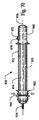
好ましい実施形態にしたがうステントおよびステントグラフトは、血管内の治療中に留置されているとき、アーチ型の構造を有しており、これにより、血管における身体構造上の湾曲に適合することが可能となっている。これは、後により詳細に説明するような2次的なアニール処理の結果としての、ステントにおける固有の形状記憶に起因する。一実施形態では、ステントは、約0°〜約180°の湾曲を有する初期構造となるように、形成あるいは製造される。特定の実施形態では、ステントは、初期構造において、約180°の湾曲を有する。留置構造では、ステントは、このステントが配置されている血管部分あるいは損傷部位の内部の湾曲に近づくような、適合性を有する。一実施形態では、ステントは、留置構造において、初期構造の湾曲とは異なる湾曲を有する。損傷部位では、ステントは、平らにされたおよび/または変形された挿入構造と、血管の湾曲に適合した留置構造との間で、可動である。
Stents and stent grafts Stents and stent grafts according to preferred embodiments have an arcuate structure when deployed during endovascular treatment, thereby adapting to anatomical curvature in the blood vessel. It is possible. This is due to the inherent shape memory in the stent as a result of the secondary annealing process as described in more detail later. In one embodiment, the stent is formed or manufactured to an initial structure having a curvature of about 0 ° to about 180 °. In certain embodiments, the stent has a curvature of about 180 ° in the initial structure. In the indwelling structure, the stent is compatible such that it approximates the curvature within the vessel portion or lesion site where the stent is located. In one embodiment, the stent has a curvature in the indwelling structure that is different from the curvature of the initial structure. At the injury site, the stent is movable between a flattened and / or deformed insertion structure and an indwelling structure adapted to the curvature of the blood vessel.
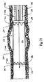
一実施形態では、血管内のステントグラフトあるいはエンドグラフト10が設けられている。ステントグラフト10は、動脈瘤、あるいはその近傍における血管内の弱い部分あるいは損傷部位を補強するために、患者の大動脈などの血管内に配置されている。一実施形態では、ステントグラフト10は、大動脈弓などの血管の湾曲部分における、血管の内部に配置されている。ステントグラフト10は、動脈瘤において傷ついている、あるいは病気の血管に強度を与え、さらに、さらなる応力および/または外傷を動脈瘤に与えることなく、ステントグラフト10を介する血液の流れを確保し、これにより、損傷部位における血管の拡張および/または破裂を防止する。特定の実施形態では、ステントグラフト10は、後により詳細に説明するような、網状のステントを含んでいる。この網状のステントは、損傷部位、あるいはその近傍における血管壁において追加的な応力ポイントを生むことなく、血管の湾曲にスムーズに近づくことを促進する。さらに、一実施形態では、網状のステントが、好適なアニーリングあるいは熱処理プロセスによって、アーチ型の初期構造に形成されている。このために、血管壁における材料の矯正応力(straightening stress)が、除去あるいは減少される。したがって、このことは、サポートステントおよび/またはステントグラフトによって血管壁に対して付加される応力を、さらに減少する。
In one embodiment, an endovascular stent graft or
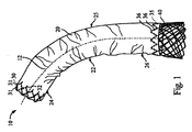
ステントグラフト10は、図1に示すように、ステントグラフト10の長手方向に沿った、縦軸12を規定している。ステントグラフト10は、このステントグラフトが配置されるべき損傷部位の長さに対応する、任意の好適な長さを有している。ステントグラフト10は、損傷部位に近接するおよび/または損傷部位から遠位の血管における内壁の表面に対して、適切にしっかりと固着されている。
The
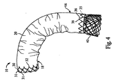
図1〜図6は、約0°〜約180°の湾曲を有するアーチ型に留置された構造となっている、例示的なステントグラフト10を示している。一実施形態では、留置構造において、ステントグラフト10は、初期構造におけるステントグラフト10の湾曲と、実質的に類似の湾曲を有している。別の実施形態では、留置構造において、ステントグラフト10は、初期構造におけるステントグラフト10の湾曲とは異なった湾曲を有している。ステントグラフト10は、例えば、約45°(図1参照)〜130°(図6参照)の湾曲を有するように、さまざまな留置構造をもって図示されている。
FIGS. 1-6 illustrate an
この明細書に示された教示事項によって導かれた当業者にとっては明らかなことではあるが、ステントグラフト10は、このステントグラフト10が内部に留置される血管部分の湾曲に対して、少なくとも大まかに対応している、任意の好適な湾曲を有する留置構造、および/または、任意の好適な湾曲を有する初期構造を有することが可能である。他の実施形態では、留置構造におけるステントグラフト10は、約45°の湾曲(図1参照)、約60°の湾曲(図2参照)、約90°の湾曲(図3および図4参照)、約110°の湾曲(図5参照)、あるいは、約130°の湾曲(図6参照)、を有している。さらに、一実施形態では、ステントグラフト10におけるアーチ型の部位は、図3に示すように、ステントグラフト10の中央部位14に配置されているか、図4に示すように、ステントグラフト10の近接部位18、あるいはその近傍に配置されているか、あるいは、ステントグラフト10の遠位部位16、あるいはその近傍に配置(図示せず)されている。
As will be apparent to those skilled in the art guided by the teachings presented in this specification, the stent-
さらに、特定の実施形態では、ステントグラフト10の遠位部位16における外径は、ステントグラフト10の近接部位18における外径とは異なっている。遠位部位16の外径は、カーブしている血管部分の遠位端部、あるいはその近傍において、血管の内径に対応している。また、近接部位18の外径は、カーブしている血管部分の近接端部、あるいはその近傍において、血管の内径に対応している。さらなる特定の実施形態では、近接部位18の外径は、遠位部位16の外径よりも大きくなっている。
Further, in certain embodiments, the outer diameter at the
グラフト
図1〜図6に示すように、ステントグラフト10は、好適な生体適合性を有する材料から形成された、グラフト20を含んでいる。この明細書に示された教示事項によって導かれた当業者にとっては明らかなことではあるが、グラフト20は、傷ついている、あるいは病気の血管に対する修復を促進するために適している、任意の好適な生体適合性を有する合成材料および/または生体材料を含むことが可能である。
Graft As shown in FIGS. 1-6,
グラフト20は、近接端部24、中央部分25および反対側の遠位端部26を規定する、本体22を有している。一実施形態では、本体22は、チューブ状の構造を有しており、カーブした血管部分の内表面に接触するように適合するための、柔軟性を有している。特定の一実施形態では、グラフト20は、カーブした血管部分の内表面に接触するような柔軟性を有する、および/または、その内表面の湾曲に適合する、好適な織物材料あるいは布地材料から形成されている。
The
図1を参照すると、近接端部24は、損傷部位においてグラフト20が留置されているときに、近接する固着位置において、血管における内壁の表面に対して、接触および/または密閉固着するように構成されている。同様に、遠位端部26は、遠位の固着位置において、前記の内壁の表面に対して、接触および/または密閉固着するように構成されている。
Referring to FIG. 1, the
一実施形態では、近接端部24が損傷部位に対して近い位置に配置されるように、グラフト20が損傷部位に配置されている。近接端部24が前記の内壁の表面に密閉固着されている場合、遠位端部26は、損傷部位に対して遠い位置に配置されている遠位の固着位
置において、血管の内壁の表面に対して、接触および/または密閉固着している。別の実施形態では、遠位端部26が損傷部位から遠い内壁の表面に対して接触あるいは固着するように、グラフト20が損傷部位に配置されている。遠位端部26が前記の内壁の表面に接触している場合、近接端部24は、損傷部位に対して近い位置に配置されている近接する固着位置において、血管の内壁の表面に対して、密閉固着している。
In one embodiment, the
アンカーステント
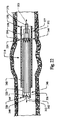
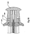
一実施形態では、縫合あるいはステッチ31のような好適な結合メカニズムを利用して、アンカーステント30が、グラフト20に結合されている。図7および図8を参照すると、アンカーステント30は、近接端部24において、グラフト20の内表面に結合されている。この実施形態では、アンカーステント30は、複数のとげ(barb)32のような、少なくとも1つの突起を含んでいる。これは、グラフト20を介して、グラフト20の外表面に対して外側に向かって延びている。特定の実施形態では、とげ32は、アンカーステント30と一体に形成されている。ステントグラフト10が、ステントグラフト10を損傷部位に正確かつ適切に配置しておくことを促進する留置構造にあるときに、とげ32は、大動脈壁のような血管壁内に対して、突き抜けるおよび/または埋め込まれるように構成されている。この明細書に示された教示事項によって導かれた当業者とっては明らかなことではあるが、任意の好適な部材あるいはメカニズムを、アンカーステント30に組み込むことが可能である。これは、ステントグラフト10を損傷部位に正確かつ適切に配置しておくために、血管壁に対して干渉および/または結合するように構成されている。
Anchor Stent In one embodiment, the
図7に示すように、アンカーステント30は、複数のダイヤモンド型の空間33を形成するように構成されている。一実施形態では、アンカーステント30は、一体的に形成されたとげ32を含んでおり、好適なレーザ切断プロセスを用いて製造される。しかしながら、この明細書に示された教示事項によって導かれた当業者とっては明らかなことではあるが、アンカーステント30に結合されている、あるいはこれと一体的に形成されているとげ32を有するアンカーステント30を製造するために、任意の好適な製造プロセスを使用することが可能である。
As shown in FIG. 7, the
固定リング
一実施形態では、固定リング35が、遠位端部26において、グラフト20に結合されている。図9に示すように、固定リング35は、縫合あるいはステッチ36などの好適な結合メカニズムを利用することによって、遠位端部26に結合されている。一実施形態では、固定リング35は、複数の尖頭(prong)37のような、少なくとも1つの突起を含んでいる。これは、固定リング35から、グラフト20によって規定される通過域38内に向かって、内側に延びている。特定の実施形態では、尖頭37は、固定リング35と一体的に形成されている。尖頭37は、サポートステント40をグラフト20内に正確に配置しておくことを促進するために、グラフト20内に配置されているサポートステント40に対して、干渉および/または結合するように構成されている。特定の実施形態では、尖頭37は、比較的に短く、かつ、鋭利度の低いものであり、これは、比較的に長くかつ鋭い、あるいは尖ったとげ32とは対称的である。この明細書に示された教示事項によって導かれた当業者とっては明らかなことではあるが、任意の好適な部材あるいはメカニズムを、固定リング35に組み込むことが可能である。これは、サポートステント40をグラフト20内に正確に配置しておくために、通過域38を流れる血流に対する所望しない妨害を招くことなく、サポートステント40に対して干渉および/または結合するように構成されている。一実施形態では、固定リング35は、一体的に形成された尖頭37を有しており、好適なレーザ切断プロセスを用いて製造される。しかしながら、この明細書に示された教示事項によって導かれた当業者とっては明らかなことではあるが、固定リング35に結合されている、あるいはこれと一体的に形成されている尖頭37を有する固
定リング35を製造するために、任意の好適な製造プロセスを使用することが可能である。
Fixation Ring In one embodiment, a
サポートステント
さらに図10および図11を参照すると、ステントグラフト10は、グラフト20(これらの図には示していない)内に配置することが可能で、かつ、グラフトの近接端部24および/またはグラフトの遠位端部26に結合された、サポートステント40を含んでいる。図10は、アーチ型の初期構造となっている、サポートステント40を示している。図11は、挿入構造となっており、部分的に留置されている(これについては、後により詳細に説明する)、サポートステント40を示している。一実施形態では、サポートステント40は、編み上げのステントである。サポートステント40については、編み上げのニチノールワイヤ(Nitinol wire)から製造することが可能である。これは、所望の形状記憶特性を有している。特定の実施形態では、サポートステント40は、以下に示すように、連続的な編み上げのニチノールワイヤから製造されている。他の実施形態では、サポートステント40は、好適な生体適合性を有する材料から形成されている。この材料は、ステンレススチール、プラチナおよび/またはチタニウム、好適な弾性特性を有する合金および/または複合材料などの、好適な金属を含む(これに限られるわけではない)。別の実施形態では、サポートステント40における少なくとも1つの部分が、好適な長さを有するポリマー材料から形成されている。この材料としては、例えば、ポリエーテルエーテルケトン(PEEK)、ポリエーテルスルホン(PES)、ポリイミド(PI)などを挙げられる。この明細書に示された教示事項によって導かれた当業者とっては明らかなことではあるが、サポートステント40は、任意の好適な生体適合性を有する、合成材料および/または生体材料を含むことが可能である。これは、傷ついている、あるいは病気の血管に対する修復のために適している。他の実施形態では、サポートステント40は、任意の好適なプロセスを用いて製造することが可能である。このプロセスは、まっすぐなステントをアーチ型の構造にアニーリングするプロセス、曲がった、あるいは湾曲したチューブをレーザ切断し、連続的なレーザ切断アーチ型ステントを形成するプロセス、あるいは、ポリマー材料を鋳造し、ポリマー鋳造アーチ型ステントを形成するプロセス、を含んでいるが、これらに限定されない。
Support Stent With further reference to FIGS. 10 and 11, the stent-
サポートステント40は、本体42を有しており、これが、近接端部44、中央部分45、および、反対側の遠位端部46を規定している。一実施形態では、近接端部44の外径および/または遠位端部46の外径は、中央部分45の外径よりも大きくなっている。さらに、近接端部44の外径については、遠位端部46の外径と同様にしても、あるいは、これと異なるようにしてもよい。一実施形態では、本体42は、チューブ状の構造を有しており、図11において方向指示矢47によって示されているように、縦軸12に対応したサポートステント40の縦軸に関して、半径方向に拡張することが可能である。
The
一実施形態では、サポートステント40は、グラフト20内に配置されている。そして、ステントグラフト10は、カテーテルのような好適な搬送デバイスを利用して、損傷部位まで搬送される。搬送デバイスは、ステントグラフト10を、平らにされた挿入構造に維持するように構成されている。これにより、ステントグラフト10が、患者の血管システムを介して損傷部位に搬送される。損傷部位では、ステントグラフト10は、部分的に留置されている。より詳細にいうと、サポートステントの近接端部44は、グラフト20に対してサポートステント40を縫合あるいはステッチすることによって、グラフトの近接端部24に結合されており、これによって留置されている。一実施形態では、とげ32が、血管壁内に対して突き抜けるおよび/または埋め込まれるように、アンカーステント30が、グラフト20に関して半径方向の外側に膨らんでいる。特定の実施形態では、サポートステントの近接端部44が、グラフトの近接端部24に結合されており、サポートステントの遠位端部46が、サポートステント40における自由に移動可能な端部部分を
規定している。例えば、サポートステントの遠位端部46が、グラフト20に対して、直接には結合あるいは接続されていない。一実施形態では、ステントグラフトの近接部位18が血管壁に結合されており、サポートステントの遠位端部46が留置されている。別の実施形態では、ステントグラフトの遠位部位16が留置されている。ステントグラフトの遠位部位16が血管壁に接触している場合には、ステントグラフトの近接部位18が留置される。
In one embodiment,
サポートステントの遠位端部46は、グラフト20の内表面に接触するように、および、グラフトの遠位端部26と結合するように、拡張可能となっている。サポートステントの遠位端部46は、尖頭37に対して、干渉および/または結合している。この尖頭37は、グラフトの遠位端部26に結合している固定リング35から、半径方向の内側に延びている。この実施形態では、尖頭37は、サポートステントの遠位端部46に対して干渉しており、これにより、グラフト20内に正確に配置されているサポートステント40を、調整および維持している。前記の留置構造では、サポートステント40は、図10および図11に示すように、血の流れる通過域48を規定している。
The
サポートステント40は、グラフト20の長さに沿って、サポートステントの近接端部44とサポートステントの遠位端部46との間に延びる、好適な長さを有している。一実施形態では、サポートステントの本体42の長さは、グラフトの本体22の長さよりも長くなっている。特定の実施形態では、サポートステントの本体42の長さは、グラフトの本体22の長さよりも、少なくとも1cm、長くなっている。例えば、サポートステントの遠位端部46は、縦軸12に沿った遠位方向(遠位方向)に、グラフトの遠位端部26を超えて、少なくとも1cm、延びている。特定の実施形態では、サポートステント40は、大動脈の切開部分をカバーするために、特定の用途による要求に応じて、さまざまな長さの範囲で、グラフトの遠位端部26を超えて拡張することが可能である。特定の実施形態では、前記の長さは、少なくとも約30cmに達することがある。
The
さらに図10および図11を参照すると、一実施形態では、サポートステント40は、網状のステントである。図10に示すように、網状のステント40は、アーチ型の初期構造を有している。これは、血管の湾曲に対応するように構成されている。一実施形態では、網状のステント40は、連続的な構造ワイヤー49を含んでいる。これは、図10において方向指示矢52によって示されているような、ステント40の軸54に関する第1の並進運動方向(translational direction)を有する、第1のらせん形のワイヤー部分50を形成している。構造ワイヤー49は、さらに、第2のらせん形のワイヤー部分56を形成している。これは、図10において方向指示矢58によって示されているような、第1の並進運動方向とは逆向きの、軸54に関する第2の並進運動方向を有しおり、また、第1のらせん形のワイヤー部分50とともに、内向きに巻かれている。一実施形態では、第1のらせん形のワイヤー部分50および第2のらせん形のワイヤー部分56は、二重らせんを形成している。ここでは、第1のらせん形のワイヤー部分50および第2のらせん形のワイヤー部分56は、同一の軸、すなわち軸54を有する、合同のらせんである。さらに、第1のらせん形のワイヤー部分50は、図10に示すような編み角度αで、第2のらせん形のワイヤー部分56と交叉している、および/または、このワイヤー部分56とともに巻き付けられている。一実施形態では、編み角度αは、少なくとも約120°である。
Still referring to FIGS. 10 and 11, in one embodiment, the
別の実施形態では、網状のステント40は、第1のらせん形のワイヤーを含んでいる。これは、図10において方向指示矢52によって示されているような、ステント40の軸54に関する第1の並進運動方向を有している。網状のステント40は、さらに、第2のらせん形のワイヤーを含んでいる。これは、図10において方向指示矢58によって示されているような、第1の並進運動方向とは逆向きの、軸54に関する第2の並進運動方向
を有している。また、この第2のらせん形のワイヤーは、第1のらせん形のワイヤーとともに、内向きに巻かれている。一実施形態では、第1のらせん形のワイヤーおよび第2のらせん形のワイヤーは、二重らせんを形成している。ここでは、第1のらせん形のワイヤーおよび第2のらせん形のワイヤーは、同一の軸、すなわち軸54を有する、合同のらせんである。
In another embodiment, the
図10および図11に示すように、第1のらせん形のワイヤー部分50は、一般的に、複数のコイル部分あるいは巻線60を含んでいる。さらに、第2のらせん形のワイヤー部分56は、複数のコイル部分あるいは巻線66を含んでいる。各コイル巻線60は、隣接するコイル巻線60に対して移動可能であり、および/または、各コイル巻線66は、隣接するコイル巻線66に対して移動可能である。これにより、コイル巻線は、対応する血管の湾曲部分における内表面に接触して、この内表面にしたがった形状となるか、あるいは、この内表面に適応する。一実施形態では、第1のらせん形のワイヤー部分50および第2のらせん形のワイヤー部分56は、それぞれ、等しい数のコイル巻線60および66を有している。このため、留置構造において、網状のステント40は、血管の内壁における湾曲に対して、スムーズに近づくことが可能となっている。この実施形態では、血管の内壁において、サポートステント40によって及ぼされる個々の応力ポイントあるいは応力エリアを削減あるいは制限した状態で、サポートステント40が、初期構造から、血管の内壁における湾曲に対応している留置構造に移動することが可能である。さらに、サポートステント40がアーチ型の初期構造を有しているため、サポートステント40は、湾曲部分内における損傷部位に配置されているときに、内部の血管壁に対して所望しない力を及ぼさない。
As shown in FIGS. 10 and 11, the first
一実施形態では、サポートステント40は、このサポートステント40にアーチ型の初期構造を付与するための、熱処理が施される。この実施形態では、サポートステント40に加えられる力は、サポートステント40を変形する可能性がある。しかしながら、この変形力が除去されれば、サポートステント40は初期構造に戻る。特定の実施形態では、サポートステント40は、アニールされた材料を含んでいる。この特定の実施形態では、サポートステント40は、これをアーチ型の初期構造に形成するために、アニールされる。一実施形態では、サポートステント40は、連続的な構造のワイヤー49を、第1のらせん形のワイヤー部分50および第2のらせん形のワイヤー部分56に形成することによって、製造される。このように形成されたサポートステント40は、その後、このステントをアーチ型の初期構造に移動および維持するために、アニールされる。この実施形態では、軸54は、サポートステント40の湾曲を規定している。このアニーリングプロセス中、材料は、長期間にわたって高温にさらされ、その後、ゆっくりと冷やされる。材料が熱せられ、その後にゆっくりと冷やされるにつれて、材料の微細構造は変化し、材料の機械的な特性が変えられる。このアニーリングプロセスは、さらに、機械加工プロセスおよび/または鋳造プロセス中に材料内に生じた、全ての内部応力を解消する。この明細書に示された教示事項によって導かれた当業者とっては明らかなことではあるが、サポートステント40をアーチ型の初期構造に形成するためには、前記の方法を含む、任意の好適なプロセスあるいは処理を使用することが可能である。
In one embodiment, the
一実施形態では、サポートステント40の本体42は、例えば、損傷部位における血管の湾曲に対する調整を促進するために、本体42の長さに応じて変化する従順性などの、格差のある従順性(differential compliance)を有している。特定の実施形態では、近接端部44は、「柔らかい」従順性あるいは剛性を有している。これは、血管における湾曲した部分あるいは角のある部分内にサポートステント40を配置することを促進するために、血管の生理学的な従順性に、少なくとも近いあるいは接近したものである。近接端部44の剛性は、血管の剛性に近いあるいは接近しており、これにより、留置されたサポートステント40を伴う血管の内壁に対してサポートステント4
0によって及ぼされる半径方向の力に起因する血管の浸食を、防止あるいは制限するようになっている。この実施形態では、遠位端部46は、近接端部44の剛性よりも高い剛性を有している。
In one embodiment, the
It prevents or limits erosion of blood vessels due to radial forces exerted by zero. In this embodiment, the
一実施形態では、好適な熱処理プロセスによって、本体42の少なくとも一部における半径方向の強度の調整を促進し、これにより、格差のある従順性を有するサポートステント40を製造するようになっている。別の実施形態では、近接端部44は、遠位端部46を含む本体42を製造するために使用される材料に比べて、より柔らかい材料から形成されている。好適な材料は、金属材料、合金材料(ニチノール材料など)、およびポリマー材料を含んでいるが、これらに限定されない。この実施形態では、近接端部44は、血管の剛性に応じた剛性を有する材料であって、近接端部44の剛性よりも高い剛性を有する材料から形成されている。さらに別の実施形態では、遠位端部46は、近接端部44の剛性よりも低い剛性を有する材料から形成されている。
In one embodiment, a suitable heat treatment process facilitates adjustment of the radial strength in at least a portion of the
搬送システム
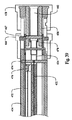
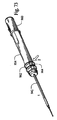
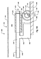
図12〜図18は、胸部大動脈瘤に対する修復治療中において、プロテーゼインプラント(ステントあるいはステントグラフトなど)を損傷部位に搬送および/または留置するための、搬送システムを示している。胸部大動脈瘤に対する修復治療中において、搬送システム130は、動脈瘤、あるいはその近傍における損傷部位に対して、ステントグラフト(例えばステントグラフト110)を、搬送および/または配置する。搬送システム130は、ワイヤールーメン132を含んでいる。このワイヤールーメン132は、患者の血管内に初めに配置されるガイドワイヤ(図示せず)の周囲に、スライドできるように配置することの可能なものである。一実施形態では、このガイドワイヤは、外科医によって、患者の大腿動脈から血管を通して進められ、大動脈内に配置される。ワイヤールーメン132は、通路(図示せず)を規定しており、これを通して、ワイヤールーメン132は、ガイドワイヤの周囲にスライド可能に配置される。一実施形態では、ステントグラフトを損傷部位に進めることを促進するために、ノーズコーン133が、ワイヤールーメン132に結合されているか、あるいは、これと一体となっている。
Delivery System FIGS. 12-18 illustrate a delivery system for delivering and / or placing a prosthetic implant (such as a stent or stent graft) to a damaged site during repair treatment for a thoracic aortic aneurysm. During repair treatment for a thoracic aortic aneurysm, the
さらに図16および図17を参照すると、一実施形態では、サポートステント126が、ワイヤールーメン132の周囲にスライド可能に配置されている。サポートステント126が平らにされた挿入構造にある場合に、内部シース134は、サポートステント126の周囲に引き抜き可能に配置されている。内部シース134は、サポートステント126の少なくとも一部の周囲に配置されている。これにより、ステントグラフト110が損傷部位に進められているときに、サポートステント126を平らにされた挿入構造に維持する。ステントグラフト110が所望どおりに血管内に配置されている場合、内部シース134は、平らにされた挿入構造から拡張された留置構造となるサポートステント126の留置を促進するために、引き抜き可能となっている。これについては、後により詳細に説明する。
Still referring to FIGS. 16 and 17, in one embodiment, a
一実施形態では、搬送システム130は、ワイヤールーメン132の周囲にスライド可能に配置された、サポート部材136を含んでいる。サポート部材136は、近接端部38、および、反対側の遠位端部140を規定している。近接端部138は、図16および図17に示すように、サポートステント126が平らにされた挿入構造にある場合に、サポートステント126の遠位端部と接触している。一実施形態では、内部シース134がサポートステント126の周囲から引き抜かれるときに、サポート部材136が、サポートステント126に対する実質的に一定の力を維持している。これにより、サポートステント126における遠位方向への所望しない動きを防止あるいは制限し、サポートステント126を、損傷部位に適切に配置しておくようになっている。特定の実施形態では、内部シース134がサポートステント126の周囲から引き抜かれるときに、サポートステ
ント126が拡張する。さまざまな実施形態では、内部シース134とサポート部材136とが反対方向に移動し、網状のステントなどのサポートステント126の短縮化を最小化することを、促進するようになっている。特定の実施形態では、反対方向への移動の比率は、約1:1〜約1:3である。
In one embodiment, the
図14に示すように、グラフト114は、内部シース34の周囲にスライド可能に配置されている。一実施形態では、上述のように、グラフと114は、アンカーステント30と、固着リング35とを有する。外部シース42は、グラフト114が搬送構造にある場合に、グラフト114の周囲に引き抜き可能に配置されている。外部シース142は、グラフト114における少なくとも一部分の周囲に配置されている。これにより、ステントグラフト110が損傷部位に進められているときに、外部シース142を搬送構造に維持する。ステントグラフト110が所望どおりに血管内に配置されている場合、外部シース142は、搬送から留置構造となるグラフト114の留置を促進するために、引き抜き可能となっている。これについては、後により詳細に説明する。
As shown in FIG. 14, the
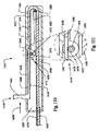
図12〜図18を参照すると、胸部大動脈瘤の修復治療中、ステントグラフト110が、損傷部位に搬送され、留置される。一実施形態では、ガイドワイヤが、患者の血管構造を介して挿入される。図13に示すように、搬送システム130内にステントグラフト110が配置されると、搬送システム130は、ガイドワイヤに沿って、損傷部位に進められる。搬送システム130は、搬送システム130の先端においてノーズコーン133を有するルーメン132によって規定される通路を介して、ガイドワイヤの周囲に配置されている。
Referring to FIGS. 12-18, during thoracic aortic aneurysm repair treatment,
搬送システム130が損傷部位につくと、外部シース142が、図14における方向指示矢144によって示されているように、遠位方向に移動する。これにより、外部シース142を引き抜き、グラフト114における少なくとも一部をむき出しにするようになっている。図15に示すように、グラフト114は、損傷部位に留置されている。グラフト114は、搬送構造と留置構造との間で、ルーメン132に関する半径方向に拡張する。留置構造では、グラフト114における外側の半径表面が、損傷部位において血管壁の内部表面に接触しており、さらに、グラフト114は、自身を通過する通路を規定している。グラフト114の近接端部118は、動脈瘤の近くに配置されている。また、遠位端部120は、動脈瘤から遠い位置に配置されている。一実施形態では、グラフト114は、アンカーステント30および固定リング35を有している。アンカーステント30は、動脈瘤の近くに配置されている。また、固定リング35は、動脈瘤から遠い位置に配置されている。
When the
一実施形態では、外部シース142、グラフト114、内部シース134および/またはサポートステント126に対して、アクチュエータが、動作可能に結合されている。このアクチュエータは、損傷部位において、図15に示すように、挿入構造にあるグラフト114を、留置構造に留置するように作動する(これについては、後により詳細に説明する)。一実施形態では、このアクチュエータは、外部シース142を引き抜くように、および、グラフト114を留置するように構成された、ハンドルを含んでいる。この実施形態では、アクチュエータは、また、内部シース134に対して動作可能に結合されており、内部シース134を引き抜き、これによってサポートステント126を留置するように構成されている。
In one embodiment, an actuator is operably coupled to the
留置されたグラフト114が損傷部位に適切に配置されると、図18に示すように、平らにされた搬送構造から拡張された留置構造へのサポートステント126の拡張を促進するために、内部シース134が、サポートステント126の周囲から引き抜かれる。留置構造では、サポートステント126の外表面が、グラフト114の内表面に接触している
。図16および図17に示すように、一実施形態では、サポート部材136が、ルーメン132の周囲に配置されている。そして、内部シース134が引き抜かれたときに、サポート部材136が、サポートステント126に接触している。これにより、損傷部位に対するサポートステント126の所望しない動きを防止あるいは制限し、サポートステント126における損傷部位への配置を維持する。特定の実施形態では、サポート部材136が、ガイドワイヤに沿って、近位方向に移動可能となっている。これにより、方向指示矢144(図14)によって示される反対の遠位方向に内部シース134が引き抜かれたときに、サポートステント126に接触するようになっている。グラフト114およびサポートステント126が損傷部位に留置されると、ガイドワイヤは、血管内から引き抜かれる。
When the deployed
「上昇型」の留置
図19〜図21を参照すると、血管内の治療中に、ステントグラフト210を損傷部位に搬送するための、装置260が設けられている。一実施形態では、ステントグラフト210を損傷部位に搬送する際に、外部シース280が、グラフト220における少なくとも一部をカバーしている。さらに、内部シース276が、外部シース280内に配置されており、ステントグラフト210を損傷部位に搬送する際に、サポートステント240における少なくとも一部をカバーしている。損傷部位では、外部シース280が、縦軸212に関する遠位方向に移動可能となっており、これにより、少なくとも部分的に、グラフト220をむき出しにする、および/または、留置する。この実施形態では、グラフト220が少なくとも部分的に留置されると、遠位リング234が、血管における内壁の表面に対して、接触および/または固着する。内部シース276は、独立に、縦軸212に関して遠位方向に移動可能である。これにより、グラフト220を留置し、少なくとも部分的に、サポートステント240をむき出しにする、および/または、留置する。サポートステント240が少なくとも部分的に留置される場合、アンカーステント236が、前記の内壁表面に対して固着される。自由に移動可能な遠位端部244を含むサポートステント240は、縦軸212に関して半径方向の外向きに拡張し、これにより、グラフト220の内表面に接触して、通過域250を形成あるいは規定する。
“Raised” Deployment Referring to FIGS. 19-21, an
一実施形態では、血管内の治療中に、損傷部位に対してステントグラフトを留置するための方法が提供される。血管内の治療中、患者の皮膚への小さな切開が、大動脈上に形成される。外科医は、大動脈にガイドワイヤを導き、このガイドワイヤを、曲がりくねった血管構造を介して、動脈瘤(例えば損傷部位)に進める。この実施形態では、ステントグラフト210は、搬送デバイス270に搭載される。搬送デバイス270は、ガイドワイヤを介して挿入され、かつ、大動脈に挿入されて、これにより、損傷部位にステントグラフト210を進める。搬送デバイス270は、損傷部位にステントグラフト210を搬送する際、ステントグラフト210を、平らにされた構造あるいは搬送構造に維持するように構成されている。一実施形態では、例えば血管造影図の撮像システムなどの撮像機器が、損傷部位に対するステントグラフト210の適切な配置を促進するために、利用される。搬送デバイス270は、血管を含む血管構造を介したステントグラフト210の前進を促進するために、挿入構造のステントグラフト210を運ぶ。
In one embodiment, a method is provided for deploying a stent graft to an injury site during endovascular treatment. During endovascular treatment, a small incision into the patient's skin is made on the aorta. The surgeon guides the guide wire through the aorta and advances the guide wire through the tortuous vasculature to the aneurysm (eg, the injury site). In this embodiment,
ステントグラフト210が損傷部位、あるいはその近傍に配置されると、外科医は、患者の心臓の位置に関して近位方向および/または遠位方向に、搬送デバイス270を移動することが可能となる。これにより、ステントグラフト210における遠位リング234を、損傷部位に関して遠位の所望する固着位置に配置する。特定の実施形態では、外部シース280が部分的に撤去される。これにより、搬送デバイス270を移動して固定リング234を配置する前に、グラフト220の近接端部226を部分的に留置する。外部シース280は、遠位方向に移動される。これにより、搬送デバイス270から外部シース280を撤去し、固定リング234を含むグラフト220の遠位端部224を留置する。
固定リング234は、縦軸212に関して半径方向の外側に移動し、これにより、遠位の固着位置において、血管における内壁の表面に接触する。固定リング234は、この内壁の表面に対して、接触するか、および/または固着される。一実施形態では、固定リング234は、動脈(腹腔動脈など)の近くの内壁の表面に接触および/または固着し、これにより、動脈を介した血流の阻害を防止あるいは制限するようになっている。
Once the
The
固定リング234が遠位の固着位置に固着されると、内部シース276は、遠位方向に移動し、これにより、搬送デバイス270から内部シース276を撤去し、アンカーステント236を含むグラフト220の近接端部226、および、サポートステント240の近接端部246を留置するようになっている。アンカーステント236は、縦軸212に関して半径方向の外側に移動し、これにより、近接した固着位置において、血管における内壁の表面に接触する。そして、アンカーステント236は、内壁の表面に対して密閉固着される。一実施形態では、アンカーステント236は、頸動脈を介する血流の阻害を防止あるいは制限するために、右頸動脈の遠位に配置され、固着される。固定リング234およびアンカーステント236は、血管における内壁の表面に固着される。ここでは、この明細書に示された教示事項によって導かれた当業者にとって既知の、好適な手法を利用する。この手法は、固定リング234の外表面、アンカーステント236および前記の内壁表面の間におけるシールの形成を促進する。これにより、グラフト220の外表面と前記の内壁表面との間の血流を許すことなく、留置構造にあるステントグラフト210内に形成された通過域250を介して、血液が流れる。損傷部位に対してステントグラフト210が留置されると、搬送デバイス270は、大動脈を介して、損傷部位から撤去される。別の実施形態では、外部シース280は、固定リング234を保持する位置に、部分的に留置される。外部シース280および内部シース276は、固定リング234およびアンカーステント236を留置するために、実質的に同時に撤去される。
When the
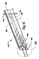
捕獲メカニズム
図22〜図24に示すように、ステントグラフト310は、グラフト320および/またはサポートステント340に対して動作可能に結合されている、捕獲メカニズム360を含んでいる。一実施形態では、捕獲メカニズム360は、グラフトの近接端部326および/またはサポートステントの近接端部346に対して結合されている。捕獲メカニズム360は、最初は、グラフトの近接端部326を挿入構造に維持するように、構成されている。後により詳細に説明するように、捕獲メカニズム360は、グラフトの近接端部326を解放するように、作動することが可能である。これにより、ステントグラフト310の近接端部が留置構造に留置されているときに、グラフト320および/またはサポートステント340における、半径方向への拡張を促進する。
Capture Mechanism As shown in FIGS. 22-24,
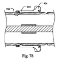
一実施形態では、図22〜図24に示すように、捕獲メカニズム360は、近接端部326に結合された複数の縫合糸ループ364を形成する、一体化された縫合糸(縫合糸)362を含んでいる。1つの特定の実施形態では、縫合糸362は、アンカーステント336内に縫いつけられている(さもなければ、これに結合されている)、複数の縫合糸ループ364を含んでいる。縫合糸362は、近接端部326に関して移動可能である。これにより、近接端部326を搬送構造に維持し、および、近接端部326を留置構造に向けて移動できるようにすることを、促進する。この実施形態では、ステントグラフト310の近接端部における断面領域を個々に減少あるいは増加するために、各縫合糸ループ364の長さを、より短くすることも、あるいは、より長くすることも可能である。さらに、後により詳細に説明するように、各縫合糸ループ364は、最初は、搬送デバイスの内部シースに対して、動作可能に結合されている。より詳細には、各縫合糸ループ364は、内部シースに結合されている対応する捕獲ワイヤーに対して、結合されている。
In one embodiment, as shown in FIGS. 22-24, the
別の実施形態では、図25に示すように、捕獲メカニズム60は、ステントグラフト3
10の外表面の周囲に巻き付けられている、ストリング366を含んでいる。ストリング366は、例えば、縫合糸のリボン、フィラメント、毛糸、木綿糸、ワイヤー、より糸、および、任意の好適な代替物を含むことが可能である。ストリング366は、最初にグラフトの近接端部326を挿入構造に維持するように構成された、複数のロッキングノット(locking knot)368を含んでいる。特定の実施形態では、ストリング366は、例えば捕獲ワイヤーに対して解放可能に結合されることによって、最初に、内部シースに対して結合されており、そして、留置構造に向かうグラフトの近接端部326における半径方向への拡張を促進するために、グラフトの近接端部326を解放するように構成されている。この他の実施形態では、ストリング366は、最初に、搬送デバイスの内部シースに対して動作可能に結合されており、グラフトの近接端部を解放するために、内部シースから解放可能となっている。
In another embodiment, as shown in FIG.
A
図25〜図28をさらに参照すると、血管内の治療中に、ステントグラフト310を損傷部位に搬送し、かつ、ステントグラフト310を損傷部位に留置するための、装置370が設けられている。装置370は、血管内の治療中に、ステントグラフトを損傷部位に搬送するための装置として、ここに説明されている。しかしながら、装置370またはその部材は、この明細書に示された教示事項によって導かれた当業者にとっては既知の、他の搬送手法とともに用いるために適している可能性もある。
With further reference to FIGS. 25-28, an
装置370は、ステントグラフト310(図22〜図24参照)、および、縦軸373を規定する搬送デバイス372を含んでいる。搬送デバイス372は、血管内の損傷部位にステントグラフト310を搬送し、かつ、この損傷部位にステントグラフト310を留置するように構成されている。一実施形態では、搬送デバイス372は、大まかに縦軸373に沿って延び、通過域375(図22参照)を規定する、ワイヤールーメン374を含んでいる。この通過域375は、ガイドワイヤ(図示せず)を支持し、搬送デバイス372およびステントグラフト310を、損傷部位に対して進めるように構成されている。内部シース376は、ワイヤールーメン374の外表面における少なくとも一部に接触するように、ワイヤールーメン374の周囲に配置されている。内部シース376は、ワイヤールーメン374および縦軸373に関して、近位方向および遠位方向に移動可能となっている。外部シース377は、内部シース376の少なくとも一部に接触するように、内部シース3766の周囲に配置されている。外部シース377は、ワイヤールーメン374および内部シース376に関して、縦軸373に沿って、独立に、近位方向および遠位方向に移動可能となっている。
一実施形態では、ステントグラフト310を損傷部位に搬送する際、外部シース377は、グラフト320の全長における少なくとも一部をカバーしている。さらに、内部シース376は、外部シース377内に配置されており、ステントグラフト310を損傷部位に搬送する際、サポートステント340の全長における少なくとも一部をカバーしている。損傷部位では、外部シース377は、グラフト320を少なくとも部分的にむき出しにし、かつ留置するために、縦軸373に関して遠位方向に移動可能となっている。この実施形態では、グラフト320が少なくとも部分的に留置されると、遠位リング334が、血管における内壁の表面に固着される。内部シース376は、サポートステント340を、少なくとも部分的にむき出しにし、かつ留置するために、縦軸373に関して遠位方向に独立に移動可能である。特定の実施形態では、サポートステント340が少なくとも部分的に留置される場合、アンカーステント336が、前記の内壁表面に対して固着される。自由に移動可能な遠位端部344を含むサポートステント340は、縦軸373に関して半径方向の外向きに拡張し、これにより、グラフト320の内表面に接触して、通過域375を形成あるいは規定する。
In one embodiment, the
一実施形態では、捕獲メカニズム360は、最初に、グラフトの近接端部326を挿入
構造に維持するように構成されている。捕獲メカニズム360は、グラフト320における半径方向への拡張を促進するために、グラフトの近接端部326を解放するように、作動することが可能である。図26に示すように、複数の捕獲ワイヤー378が、内部シース376に結合されている。各捕獲ワイヤー378は、遠位端部において、内部シース376に結合されており、反対側の近接端部において、捕獲メカニズム360に対して解放可能に結合されている。特定の実施形態では、図27に示すように、各捕獲ワイヤー378は、遠位端部において、リング379に結合されている。リング379は、内部シース376に一体化されているか、あるいは、好適なカプラを用いることによって、これに結合されている。このカプラは、例えば、縫合糸、および/または、この明細書に示された教示事項によって導かれた当業者にとって既知の、別の好適なカプラである。さらに、この特定の実施形態では、各捕獲ワイヤー378は、近接端部において、対応する縫合糸ループ364に対して解放可能に結合されている。この縫合糸ループ364は、捕獲メカニズム360における一体化された縫合糸362によって形成されている。
In one embodiment, the
別の実施形態では、捕獲メカニズム360が、ステントグラフト310の外表面の周囲に巻き付けられたストリング366を含んでおり、ストリング346が、各捕獲ワイヤー378に対して動作可能に結合されている。より詳細には、ストリング366は、図25に示すように、最初に、グラフトの近接端部326を挿入構造に維持するように構成された、複数のロッキングノット368を含んでいる。ストリング366は、グラフトの近接端部326の解放を促進するために、各捕獲ワイヤー378からロッキングノット368が分離するように構成されており、これにより、近接端部326が留置構造に向けて半径方向の外側に移動することを可能とするようになっている。
In another embodiment,
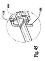
図26および図28をさらに参照すると、搬送デバイス372は、外部シース377および内部シース376の近くに配置されている、ノーズコーン380を含んでいる。ノーズコーン380は、ノーズコーン380のシャフト部分384内に規定された、複数の捕獲ワイヤーチャネル382を含んでいる。一実施形態では、各捕獲ワイヤーチャネル382は、搬送デバイス372の縦軸373の周囲に放射状に配置されており、この縦軸373に沿って並行に延びている。特定の実施形態では、各捕獲ワイヤーチャネル382は、隣接する捕獲ワイヤーチャネル382に対して、約120°で放射状に配置されている。この明細書に示された教示事項によって導かれた当業者にとっては明らかなことではあるが、任意の好適な数の捕獲ワイヤーチャネル382を、シャフト部分384内に規定することが可能である。これにより、好適な数の捕獲ワイヤー378を、対応する捕獲ワイヤーチャネル382を介して供給すること、および、捕獲メカニズム360内に形成された対応する縫合糸ループ364に対して、解放可能に結合することが可能となる。
With further reference to FIGS. 26 and 28, the
一実施形態では、一体化された縫合糸362は、3個(3)の縫合糸ループ364を形成している。他の実施形態では、一体化された縫合糸362は、少なくとも6個(6)の縫合糸ループ364から24個(24)の縫合糸ループ364を形成している。この明細書に示された教示事項によって導かれた当業者にとっては明らかなことではあるが、ステントグラフト310の近接端部を、要望どおりに、望ましくない荷重プロファイル(loading profile)の増加を伴うことなく、挿入構造あるいは部分的に留置構造に維持するために、任意の好適な数の縫合糸ループ364(および、対応する捕獲ワイヤー378)を設けることが可能である。複数の縫合糸ループ364は、所望の近接する固着位置において、グラフトの近接端部326における均一な捕獲、および/または、グラフトの近接端部326における均一な解放を促進する。これにより、損傷部位に対するステントグラフト310の適切な配置を、促進する。
In one embodiment, the
図26および図28に示すように、縫合糸捕獲溝386が、ノーズコーン380内における、ノーズコーン380のシャフト部分384とリード部分388との間に、規定され
ている。縫合糸捕獲溝386は、ノーズコーン380の周囲に放射状に、かつ、縦軸373に対して実質的に垂直に延びている。縫合糸捕獲溝386は、各捕獲ワイヤーチャネル382に交叉しており、これにより、捕獲ワイヤーチャネル382と縫合糸捕獲溝386との間のコミュニケーションをとるようになっている。一実施形態では、各捕獲ワイヤー378は、対応する捕獲ワイヤーチャネル382を介して、捕獲ワイヤーチャネル382の遠位端部から近接端部に向かって、縫合糸捕獲溝386まで延びている。捕獲メカニズム360によって形成された各縫合糸ループ364は、縫合糸捕獲溝386内において、対応する捕獲ワイヤー378に対して、解放可能に結合されている。
As shown in FIGS. 26 and 28, a
この実施形態では、グラフトの遠位端部324を留置するために、外部シース377が、縦軸373に沿って、遠位端部に移動可能となっている。グラフトの遠位端部324が留置されると、遠位リング334が、血管における内壁の表面に固着される。その後、グラフトの近接端部326および/またはアンカーステント336を留置するために、内部シース376が、縦軸373に沿って、遠位方向に移動可能となる。内部シース376が遠位方向に移動されるとき、各捕獲ワイヤー378は、対応する縫合糸ループ364から分離される。各捕獲ワイヤー378が、対応する縫合糸ループ364から分離されるとき、グラフト320の近接端部326は、半径方向の外側に、留置構造に向かって移動する。グラフトの遠位端部324が留置されるときに、近接端部326を挿入構造あるいは部分的に留置構造に維持することによって、ステントグラフト310が、完全に留置され、血管における内壁の表面に固着される前に、近接端部326を、正確に配置することが可能となる。
In this embodiment, an
図25をさらに参照すると、別の実施形態では、捕獲リボン366のロッキングノット368が、最初に、捕獲ワイヤー378に対して解放可能に結合される。内部シース376が遠位方向に移動するとき、各捕獲ワイヤー378は、ストリング366から分離される。各捕獲ワイヤー378がストリング366から分離されるとき、グラフト320の近接端部326は、半径方向の外側に、留置構造に向かって移動する。グラフトの遠位端部324が留置されるときに、近接端部326を搬送構造あるいは部分的に留置構造に維持することによって、ステントグラフト310が、完全に留置され、血管における内壁の表面に固着される前に、近接端部326を、正確に配置することが可能となる。
With further reference to FIG. 25, in another embodiment, the locking
一実施形態では、遠位リング334を含むステントグラフト310の遠位端部を留置するために、外部シース377が撤去されたときに、この方法は、最初に、ステントグラフト310の近接端部を、挿入構造に維持することを含む。遠位リング334は、血管壁に固着される。その後、アンカーステント336を含むステントグラフト310の近接端部を留置するために、搬送デバイス372の内部シース376が撤去される。そして、アンカーステント336が、固着位置の近傍において、血管壁に固着される。
In one embodiment, when the
この実施形態では、捕獲メカニズム360は、ステントグラフト310の近接端部に対して、および、複数の捕獲ワイヤー378に対して、動作可能に結合されている。これらは、独立に、内部シース376に結合されている。捕獲メカニズム360は、最初に、グラフトの近接端部326を搬送構造に維持する。ステントグラフト310の近接端部が搬送構造に維持されている場合、ステントグラフト310の近接端部は、所望の近接した固着位置において、損傷部位に対して配置されている。捕獲メカニズム360は、ステントグラフトの近接端部における半径方向への拡張を促進するために、グラフトの近接端部326を解放するように作動する。ステントグラフト310の近接端部を留置するために、内部シース376が撤去される。これにより、内部シース376の近接端部に結合されている捕獲ワイヤー378が、捕獲メカニズム360から解放される。
In this embodiment,
特定の実施形態では、捕獲メカニズム360は、グラフトの近接端部326に結合され
ている、一体化された縫合糸362を含んでいる。一体化された縫合糸362は、縫合糸ループ364を形成するために、グラフトの近接端部326および/またはアンカーステント336内に縫いつけられている。各捕獲ワイヤー378は、対応する縫合糸ループ364に対して、解放可能に結合されている。内部シース376が、遠位方向に移動する。これにより、各捕獲ワイヤー378を、捕獲メカニズム360上に形成されている対応する縫合糸ループ364から分離し、これによって、捕獲メカニズム360およびグラフトの近接端部326を作動させる。
In certain embodiments, the
一実施形態では、搬送デバイス372のノーズコーン380は、好適な数の捕獲ワイヤーチャネル382を規定する。各捕獲ワイヤーチャネル382は、搬送デバイス372の縦軸373の周囲に、放射状に配置され、かつ、これに並行に延びている。縫合糸捕獲溝386は、ノーズコーン380内に規定されている。縫合糸捕獲溝386は、ノーズコーン380の周囲に放射状に、かつ、縦軸373に対して実質的に垂直に、延びている。縫合糸捕獲溝386は、各捕獲ワイヤーチャネル382と交叉しており、これにより、各捕獲ワイヤーチャネル382と縫合糸捕獲溝386との間のコミュニケーションをとるようになっている。各捕獲ワイヤー378は、最初に、対応する捕獲ワイヤーチャネル382を介して、縫合糸捕獲溝386内に供給される。この場合、各捕獲ワイヤー378は、縫合糸捕獲溝386内において、捕獲メカニズム360内に形成されている、対応する縫合糸ループ364に結合される。
In one embodiment, the
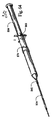
搬送デバイスアクチュエータ
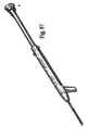
図29〜図31を参照すると、一実施形態では、搬送システム130は、アクチュエータ150を含んでいる。アクチュエータ150は、内部シース134および外部シース142に対して動作可能に結合されている、ハンドル152を有している。ハンドル152は、チャンバ155を規定する筐体154を含んでいる。ハンドル152は、さらに、外部シース引き抜きチューブ156を含んでいる。これは、チャンバ155内に、スライド可能に配置されており、近接端部において、外部シース142に結合されている。筐体154に対する外部シース引き抜きチューブ156の移動を促進するために、引き抜き素子158が、外部シース引き抜きチューブ156の遠位端部に結合されている。図29に示すように、外部シース142を引き抜き、かつ、グラフト114を留置するために、外部シース引き抜きチューブ156は、筐体154に対して、遠位方向においてスライド可能に移動可能となっている。この実施形態では、外部シース142が引き抜かれたとき、グラフト114は、半径方向に拡張し、これによって血管壁の内表面に接触する。別の実施形態では、アクチュエータ150は、損傷部位において、搬送構造にあるグラフト114を留置構造に留置するように、作動する。
Transport Device Actuator Referring to FIGS. 29-31, in one embodiment, the
図29に示すように、第1の固定素子160が、外部シース引き抜きチューブ156の周囲に配置されており、外部シース引き抜きチューブ156を固定位置に固定するように構成されている。これにより、ステントグラフト110が損傷部位に搬送および/または配置されたときに、筐体154内における外部シース引き抜きチューブ156の動きを、防止あるいは制限するようになっている。ステントグラフト110が損傷部位に対して適切に配置されると、第1の固定素子160が解除され、そして、外部シース引き抜きチューブ156が、筐体154に関して遠位方向に引き出される。これにより、外部シース142が引き抜かれる。
As shown in FIG. 29, the
ハンドル152は、また、内部シース引き抜きチューブ162を含んでいる。これは、図30に示すように、外部シース引き抜きチューブ156の周囲にスライド可能に配置されている。内部シース引き抜きチューブ162は、近接端部において、内部シース134に対して結合されている。そして、第1の固定素子160が、内部シース引き抜きチューブ162における反対側の遠位端部に結合されている。図30に示すように、内部シース
134を引き抜き、サポートステント126を留置するために、内部シース引き抜きチューブ162は、外部シース引き抜きチューブ156に対して、遠位方向においてスライド可能に移動可能となっている。一実施形態では、第2の固定素子164が、筐体154に結合されており、内部シース引き抜きチューブ162を固定位置に固定するように構成されている。これにより、ステントグラフト110が損傷部位に搬送および/または配置されたときに、外部シース引き抜きチューブ156に対する内部シース引き抜きチューブ162の動きを、防止あるいは制限するようになっている。ステントグラフト110が損傷部位に対して適切に配置されると、第2の固定素子が解除され、内部シース引き抜きチューブ162が、外部シース引き抜きチューブ156に関して遠位方向に引き出される。これにより、内部シース134が引き抜かれる。
Handle 152 also includes an inner
図31を参照すると、一実施形態では、外部シース引き抜きチューブ156および/または内部シース引き抜きチューブ162は、非円形の断面領域を有している。この領域は、外部シース引き抜きチューブ156および/または内部シース引き抜きチューブ162における望ましくない回転運動を、防止あるいは制限するように構成されている。
Referring to FIG. 31, in one embodiment, outer
この実施形態では、ステントグラフト110が損傷部位に対して適切に配置されると、第1の固定素子160が解除される。引き抜き素子158、および、これに結合された外部シース引き抜きチューブ156は、遠位方向にスライドされ、これにより外部シース142が引き抜かれ、これによって損傷部位にグラフト114が留置される。その後、第2の固定素子164が解除され、第1の固定素子160、および、これに結合された内部シース引き抜きチューブ162が、サポートステント126の周囲に配置されている内部シース134を引き抜くように、遠位方向にスライドされる。内部シース134が引き抜かれたとき、サポートステント126は、平らにされた搬送構造から、拡張された留置構造に拡張する。留置構造では、サポートステント126の外表面は、グラフト114の内表面に接触する。特定の実施形態では、第1の固定素子160および第2の固定素子164が解除され、そして、引き抜き素子158および第1の固定素子160が、実質的に同時に、遠位方向にスライドされる。これにより、損傷部位に対して、グラフト114およびサポートステント126が留置される。
In this embodiment, the
図32〜図41を参照すると、一実施形態では、アクチュエータ450は、内部シース434および外部シース442に対して操作可能に結合された、ハンドル452を含んでいる。
With reference to FIGS. 32-41, in one embodiment, the
ハンドル452は、チャンバ455を規定する、筐体454を含んでいる。ハンドル452は、さらに、外部シース引き抜きチューブ456を含んでいる。これは、筐体454内に、スライド可能に配置されており、外部シース442の遠位端部に対して結合されている。筐体454に対する外部シース引き抜きチューブ456の移動を促進するために、第1の引き抜き素子458が、外部シース引き抜きチューブ456の遠位端部に結合されている。図32に示すように、外部シース442を引き抜き、かつ、グラフト414を留置するために、外部シース引き抜きチューブ456は、筐体454に対して、遠位方向(方向指示矢457によって示されている)に、スライド可能に移動可能となっている。一実施形態では、第1の引き抜き素子458は、筐体454内における外部シース引き抜きチューブ456の移動を防止あるいは制限するために、外部シース引き抜きチューブ456を固定位置に固定するように構成されている。
Handle 452 includes a
図32に示すように、外部シース442を引き抜き、かつ、グラフト414を留置するために、外部シース引き抜きチューブ456は、筐体454に対して、遠位方向にスライド可能に移動可能となっている。この実施形態では、外部シース442が引き抜かれたとき、グラフト414は、半径方向に拡張し、これにより、血管壁の内部表面に接触する。
別の実施形態では、アクチュエータ450は、挿入構造にあるグラフト414を、損傷部位に留置構造に留置するように作動する。
As shown in FIG. 32, the outer
In another embodiment, the
第1の引き抜き素子458は、外部シース引き抜きチューブ556の周囲に配置されており、外部シース引き抜きチューブ456を固定位置に固定するように構成されている。これにより、ステントグラフト410が損傷部位に対して搬送および/または配置されたときに、筐体454内における外部シース引き抜きチューブ456の動きを、防止あるいは制限するようになっている。ステントグラフト410が損傷部位に対して適切に配置されると、第1の引き抜き素子458は、外部シース引き抜きチューブ456に対して回転され、これにより、外部シース引き抜きチューブ456を解除する。その後、外部シース引き抜きチューブ456は、外部シース442を引き抜くために、筐体454に関して遠位方向に引き出される。
The
ハンドル452は、さらに、内部シース引き抜きチューブ462を含んでいる。これは、図33に示すように、外部シース引き抜きチューブ456の周囲にスライド可能に配置されている。内部シース引き抜きチューブ462は、近接端部において、内部シース434に対して結合されている。そして、第2の引き抜き素子464が、内部シース引き抜きチューブ462における反対側の遠位端部に結合されている。図33に示すように、内部シース434を引き抜き、サポートステント426を留置するために、内部シース引き抜きチューブ462は、外部シース引き抜きチューブ456に対して、遠位方向においてスライド可能に移動可能となっている。一実施形態では、第2の引き抜き素子464が、内部シース引き抜きチューブ462を固定位置に固定するように構成されている。これにより、ステントグラフト410が損傷部位に対して搬送および/または配置されたときに、外部シース引き抜きチューブ456に対する内部シース引き抜きチューブ462の動きを、防止あるいは制限するようになっている。ステントグラフト410が損傷部位に対して適切に配置されると、第2の引き抜き素子464が解除位置に回転され、内部シース引き抜きチューブ462が、外部シース引き抜きチューブ456に関して遠位方向に引き出される。これにより、外部シース442が引き抜かれる。
The
図34を参照すると、一実施形態では、外部シース引き抜きチューブ456および/または内部シース引き抜きチューブ462は、非円形の断面領域を有している。この領域は、外部シース引き抜きチューブ456および/または内部シース引き抜きチューブ460における望ましくない回転運動を、防止あるいは制限するように構成されている。
Referring to FIG. 34, in one embodiment, outer
さらに図35〜図41を参照すると、ステントグラフト410が損傷部位に対して適切に配置された場合、図35に示すように、第1の引き抜き素子458は、解除位置に回転される。外部シース引き抜きチューブ456は、筐体454に対して遠位方向457にスライドされ、これにより、搬送構造にあるアンカーステント414の周囲に配置されている外部シース442を引き抜き、これによって、図36に示すように、損傷部位に対してグラフト414を留置するようになっている。その後、第2の引き抜き素子464が、解除位置に回転され、内部シース引き抜きチューブ462が遠位方向にスライドされる。これにより、図37に示すように、平らにされた搬送構造にあるサポートステント426の周囲に配置されている、内部シース434が引き抜かれる。内部シース434が引き抜かれると、サポートステント426は、平らにされた搬送構造から、拡張された留置構造に拡張する。留置構造では、サポートステント426の外表面が、グラフト414の内表面に接触する。特定の実施形態では、第1の引き抜き素子458および第2の引き抜き素子464が解除され、そして、外部シース引き抜きチューブ456および内部シース引き抜きチューブ462が、実質的に同時に、遠位方向にスライドされる。これにより、グラフト414およびサポートステント426が、損傷部位に留置される。
Still referring to FIGS. 35-41, when the
図38に示すように、一実施形態では、第1の引き抜き素子458が、ピン465のような突起部を形成している。これは、外部シース引き抜きチューブ456内に規定されているスロット466内に、移動可能に配置されている。第1の引き抜き素子458が回転され、これにより、ピン465がスロット466に沿って移動する。これによって、図38に示すように、第1の引き抜き素子458が、固定位置と解除位置との間で動かされる。第1の引き抜き素子456が解除位置にある場合、外部シース引き抜きチューブ456は、外部シース442を引き抜くために、遠位方向に引き出される。この実施形態では、ピン465は、図39に示すように、外部シース442に結合されているポスト467に干渉する。これにより、外部シース引き抜きチューブ456が、遠位方向に引き出された、あるいは、この方向に引っ張られたときに、外部シース442を引き抜くようになっている。同様に、第2の引き抜き素子464は、図38に示すように、ピン468のような突起部を形成している。これは、内部シース引き抜きチューブ462内に規定されているスロット469内に、移動可能に配置されている。第2の引き抜き素子464が回転され、これにより、ピン468がスロット469に沿って移動する。これによって、図38に示すように、第2の引き抜き素子464が、固定位置と解除位置との間で動かされる。第2の引き抜き素子464が解除位置にある場合、内部シース引き抜きチューブ462は、内部シース434を引き抜くために、遠位方向に引き出されるか、あるいは引っ張られる。図38〜図41を参照すると、ピン468は、内部シース434に結合されているポスト470に干渉する。これにより、図39に示すように、内部シース引き抜きチューブ462が引き出されたときに、内部シース434を引き抜くようになっている。さらに、図39〜図41に示すように、縫合糸472が、ポスト470を、アンカーピン474を介して、サポート部材436に結合している。一実施形態では、サポート部材436は、縫合糸472の結合されている、ブロック476のような突起部を含んでいる。図40および図41を参照すると、縫合糸472は、筐体454に対して動作可能に結合されている、スピンドル477の周囲に巻き付けられている。内部シース434が遠位方向に引き抜かれたとき、縫合糸472によって内部シース434に結合されているサポート部材436は、反対の近位方向に移動する。これにより、損傷部位に適切に配置されているサポートステント426を維持する。
As shown in FIG. 38, in one embodiment, the
図42〜図46を参照すると、別の実施形態では、内部シース引き抜きチューブ462は、カムシステム478を駆動するために引き抜かれる。このカムシステム478は、内部シース引き抜きチューブ462が引き抜かれたときに、サポート部材436を進めるものである。この実施形態では、サポート部材436は、らせん形のトラック481を形成する、第1の、または遠位のカム位置480を含んでいる。このトラック481は、サポート部材436が近位方向に進められているときに、筐体454に対して固定的に結合されている前進ピン482と連携する。第1のカム位置480と前進ピン482との連携により、近位方向へのサポート部材436の前進が促進される。サポート部材436は、さらに、らせん形の進路485を形成する、第2の、または近位のカム位置484を含んでいる。この進路485は、サポート部材436が近位方向に進められているときに、筐体454に対して固定的に結合されている回転ピン486と連携する。第2のカム位置484と回転ピン486との連携により、サポート部材436の回転が促進される。特定の実施形態では、少なくとも1つのレール488が、筐体454に結合されているか、あるいは、筐体454内に形成されている。これにより、内部シース引き抜きチューブ462が引き抜かれて、カムシステム478が駆動されたときに、内部シース引き抜きチューブ462によって生成される合理的な力(rational forces)および/またはトルク応力への抵抗を、促進する。図44に示すように、サポート部材436が進められているときに、近接端部438が回転しないように、サポート部材436の近接端部438が、第2のカム位置484に結合されている。さらに、特定の実施形態では、図46に示すように、ブレード490が、筐体454の近接端部に対して取り付けられている。これにより、外部シース442を切断および/または分離することによって、外部シース4
42が引き抜かれたときに、カムシステム478(図46には示していない)と干渉することなく、カムシステム478を片づけることを促進するようになっている。
With reference to FIGS. 42-46, in another embodiment, the inner
When 42 is withdrawn, it facilitates clearing the
図47〜図49を参照すると、一実施形態では、アクチュエータ550が、内部シース534および/または外部シース542に対して動作可能に結合されている、ハンドル552を有している。ハンドル552は、チャンバ555を規定している筐体554を含んでいる。筐体554は、図47に示すように、軸556、および、軸556における少なくとも一部に沿った、トラック557を規定している。一実施形態では、トラック557は、少なくとも1つの固定溝558、および/または、少なくとも1つの中間溝559を、規定あるいは包含している。
47-49, in one embodiment, the
第1の引き抜き素子560は、筐体554の周囲に配置されており、外部シース542に対して動作可能に結合されている。第1の引き抜き素子560は、例えば第1の引き抜き素子560を回転することによって、固定位置と解除位置との間で移動可能である。固定位置では、第1の引き抜き素子560が、第1の固定溝558内に配置されており、これにより、ステントグラフト510が損傷部位に対して搬送および/または配置されたときに、外部シース542の動きを防止あるいは制限するようになっている。ステントグラフト510が損傷部位に対して適切に配置されると、第1の引き抜き素子560が解除され、トラック557内で、方向指示矢561によって示すように、遠位方向にスライド可能に移動可能となり、これにより、図47に示すように、外部シース542が引き抜かれる。
The
第2の引き抜き素子562は、筐体554の周囲に配置されており、グラフト514に対して動作可能に結合されている。第2の引き抜き素子562は、例えば第2の引き抜き素子562を回転することによって、固定位置と解除位置との間で移動可能である。固定位置では、第2の引き抜き素子562が、中間の固定溝559内に配置されており、これにより、ステントグラフト510が損傷部位に対して搬送および/または配置されたときに、グラフト514の動きを防止あるいは制限するようになっている。図48に示すように、ステントグラフト510が損傷部位に対して適切に配置されると、第2の引き抜き素子562が解除され、筐体554に関して遠位方向にスライド可能に移動可能となり、これにより、後により詳細に説明するように、グラフト514が留置される。
The
第3の引き抜き素子564は、筐体554の周囲に配置されており、内部シース534に対して動作可能に結合されている。第3の引き抜き素子564は、例えば第3の引き抜き素子564を回転することによって、固定位置と解除位置との間で移動可能である。固定位置では、第3の引き抜き素子564が、固定溝558内に配置されており、これにより、ステントグラフト510が損傷部位に対して搬送および/または配置されたときに、内部シース534の動きを防止あるいは制限するようになっている。ステントグラフト510が損傷部位に対して適切に配置されると、第3の引き抜き素子564が解除され、筐体554に関して遠位方向にスライド可能に移動可能となり、これにより、図49に示すように、内部シース534が引き抜かれ、そして、サポートステント526が留置される。
The
この実施形態では、ステントグラフト510が損傷部位に対して適切に配置されると、第1の引き抜き素子560が、対応する固定溝558内で回転され、これにより、第1の引き抜き素子560が解除される。図47に示すように、第1の引き抜き素子560は、筐体554に関して遠位方向に引き出されるか、あるいは引っ張られる。これにより、搬送構造にあるグラフト514の周囲に配置されている外部シース542を、引き抜くようになっている。第2の引き抜き素子562は、中間溝559内で回転され、図48に示すように、筐体554に関して遠位方向に引き出されるか、あるいは引っ張られる。これに
より、グラフト514を、損傷部位に留置する。第3の引き抜き素子564は、対応する固定溝558内で回転される。これにより、筐体554の周囲に配置され、内部シース534に対して動作可能に結合されている第3の引き抜き素子564を、解除する。第3の引き抜き素子564は、筐体554に関して遠位方向に引き出されるか、あるいは引っ張られる。これにより、平らにされた搬送構造にあるサポートステント526の周囲に配置されている、内部シース534が引き抜かれる。内部シースが引き抜き位置にある場合、サポートステント526は、平らにされた搬送構造から、拡張構造に拡張することが可能となる。この場合、サポートステント526の外表面は、グラフト514の内表面に接触する。特定の実施形態では、第1の引き抜き素子560、第2の引き抜き素子562および第3の引き抜き素子564は、解除され、遠位方向に対して実質的に同時にスライドされる。これにより、グラフト514およびサポートステント526を、損傷部位に留置する。
In this embodiment, when the stent graft 510 is properly positioned relative to the injury site, the
図50〜図53を参照すると、一実施形態では、アクチュエータ650が、内部シース634および/または外部シース642に対して動作可能に結合されている、ハンドル652を有している。ハンドル652は、チャンバ655を規定している筐体654を含んでいる。このチャンバ655内では、内部シース634および/または外部シース642が、引き抜き位置に配置可能となっている。筐体654は、図50に示すように、軸656、および、軸656における少なくとも一部に沿った、トラック657を規定している。一実施形態では、トラック657は、筐体654を介して延びており、チャンバ655と連通している。
Referring to FIGS. 50-53, in one embodiment, the actuator 650 has a
引き抜き素子660は、筐体654の周囲に配置されており、外部シース642に対して動作可能に結合されている。一実施形態では、コネクタ661が、外部シース642を引き抜き素子660に結合している。図51に示すように、コネクタ661は、外部シース642に結合されており、また、引き抜き素子660に結合するように、トラック657を介して延びている。引き抜き素子660は、固定素子662によって、軸656に沿った初期の位置に維持される。この固定素子662は、筐体654によって規定された開口部(図示せず)内に延びている。固定素子662は、最初に、引き抜き素子660および/または外部シース642における軸656に沿った動きを、防止あるいは制限するように構成されている。一実施形態では、固定素子662を、筐体654内から取り外すことが可能となっている。これにより、引き抜き素子660が、筐体654の長さに沿って移動することが可能となる。別の実施形態では、筐体654との結合ポイントあるいは結合領域において、固定素子662を外すことが可能となっている。これにより、引き抜き素子660が、筐体654の長さに沿って移動することが可能となる。引き抜き素子660は、固定位置と解除位置との間で、筐体654に対して回転可能となっている。固定素子662が筐体654内の開口部から除去され、引き抜き素子660が解除位置に回転されると、引き抜き素子660は、初期の位置(図50参照)と第1の停止位置(図52参照)との間で、筐体654に関して遠位方向にスライド可能に移動可能となり、これにより、外部シース642を引き抜くようになっている。図52に示すように、第1の停止位置コネクタ661は、内部シース634に対して結合された、コネクタ663に接触している。コネクタ663は、少なくとも部分的に、トラック657内に配置されている。これにより、チャンバ655内での内部シース634の望ましくない回転の防止を促進する。一実施形態では、図53に示すように、引き抜き素子660が第1の停止位置から第2の、すなわち最終の停止位置に移動されるときに、コネクタ663が、コネクタ661に干渉するように構成されている。引き抜き素子660が最終の停止位置に向かって動いているとき、コネクタ663は、内部シース634を引き抜くために、筐体654の遠位端部に結合している、および/または、この遠位端部と一体化している逆転防止具664に向けて、トラック657に沿って移動する。
The
一実施形態では、ステントグラフト610が損傷部位に対して適切に配置されると、固定素子662が、例えば、筐体の結合領域において固定素子662を外すことによって、筐体654から除去される。引き抜き素子660は、解除位置に回転される。一実施形態では、引き抜き素子660は、図51において方向指示矢665によって示されるような回転方向に回転される。別の実施形態では、引き抜き素子660は、図51に示された回転方向とは逆の回転方向に回転するように構成されている。引き抜き素子660は、初期位置(図51参照)と第1の停止位置(図52参照)との間で、筐体654に関して遠位方向に引き出されるか、あるいは引っ張られる。これにより、外部シース642を引き抜き、かつ、グラフト114を損傷部位に留置するようになっている。引き抜き素子660は、図53に示すように、第1の停止位置と、逆転防止具664、あるいはその近傍における最終の停止位置との間で、筐体654に関して遠位方向に、スライド可能に移動可能である。これにより、内部シース634を引き抜き、かつ、サポートステント126を損傷部位に留置する。グラフト114が損傷部位に留置されると、サポートステント126における外部表面の少なくとも一部が、グラフト114における内部表面の少なくとも一部に接触するように、サポートステント126が留置される。
In one embodiment, once the stent graft 610 is properly positioned relative to the injury site, the anchoring
図54〜図58を参照すると、一実施形態では、アクチュエータ750が、内部シース734および/または外部シース742に対して動作可能に結合された、ハンドル752を有している。ハンドル752は、チャンバ755を規定している筐体754を含んでいる。このチャンバ755は、筐体754の長さにおける少なくとも一部、および、軸756に沿っている。さらに図56および図57を参照すると、外部シース742および/または内部シース734における少なくとも一部が、チャンバ755内で、スライド可能に移動可能となっている。
54-58, in one embodiment, the
一実施形態では、スプリングなどの付勢用素子758が、チャンバ755内に配置されている。付勢用素子758は、第1の端部において、筐体754の遠位端部760に結合されており、さらに、第2の端部において、外部シース742に結合されている。この実施形態では、付勢用素子758は、遠位端部760に向けて、外部シース742を付勢する。プッシュボタン762は、筐体754の内部に配されておよび/または、この筐体754に結合されており、外部シース742を搬送構造に維持するように構成されている。図55に示すように、プッシュボタン762は、外部シース742を搬送構造に維持するために、チャンバ755内に延びている。プッシュボタン762は、搬送位置と、外部シース742の引き抜きを促進する押圧位置との間で移動可能となっている。搬送位置では、プッシュボタン762は、外部シース742を搬送構造に維持している。より詳細には、プッシュボタン762は、図55に示すように、付勢用素子758を拡張位置に維持するために、外部シース742を固定するか、あるいは、これに干渉するように構成されている。一実施形態では、安全用ピン764が、プッシュボタン762を初期の位置に維持するように構成されている。プッシュボタン762は、通過域を規定しており、この通過域を介して、安全用ピン764が延びている。これにより、プッシュボタン762が筐体754に関して内側に移動することを、防止する。
In one embodiment, a biasing
安全用ピン764を取り外すと、プッシュボタン762が押し下げられ、これによって、外部シース742が解放されて、さらに、付勢用素子758が慣性位置に跳ね返ることが可能となる。付勢用素子758が慣性位置に向けて動くと、付勢用素子758は、外部シース742を遠位端部760に向けて付勢する。これにより、図56に示すように、外部シース742が引き抜かれ、そして、グラフト714が留置される。一実施形態では、外部シース742が引き抜かれると、内部シース734が回転し、かつ、部分的に引っ込む。これにより、サポートステント126の一部が拡張することが可能となる。引き抜き素子766は、筐体754の周囲に配置され、さらに、内部シース734に対して動作可能に結合されている。特定の実施形態では、コネクタ768は、図55および図66に示
すように、引き抜き素子766を内部シース734に結合する。引き抜き素子766は、固定位置と解除位置との間で、筐体754に対して回転可能である。解除位置では、引き抜き素子766は、コネクタ768を、筐体754内に規定されているスロットあるいはトラックにあわせて配置することを促進する。解除位置では、引き抜き素子766は、内部シース734を引き抜くために、図57において方向指示矢769によって示すような筐体754に関する遠位方向に、スライド可能に移動可能である。
When the
一実施形態では、スプリングなどの第2の付勢用素子770が、チャンバ755内に配置されている。付勢用素子770は、第1の端部において、筐体754の遠位端部760に結合されており、さらに、第2の端部において、コネクタ768と結合されている。この実施形態では、付勢用素子770は、内部シース734を、遠位端部760に向けて付勢する。第2のプッシュボタン(図示せず)は、筐体754内に配置されているか、あるいは、この筐体754と結合されており、内部シース734を搬送構造に維持するように構成されている。特定の実施形態では、前記のプッシュボタンは、内部シース734を搬送構造に維持するために、チャンバ755に延びている。このプッシュボタンは、搬送位置と、内部シース734を引き抜くことを促進する押圧位置との間で移動可能である。搬送位置では、プッシュボタンは、内部シース734を初期の搬送構造に維持する。 一実施形態では、ステントグラフト110が損傷部位に対して適切に配置されると、プッシュボタン762を初期の位置に維持している安全用ピン764が、筐体754から外される。外部シース742を解放し、かつ外部シース742を引き抜くために、プッシュボタン762が押圧されると、グラフト114が自動的に留置される。プッシュボタン762を筐体754に対して動かすためにプッシュボタン762を押圧することによって、外部シース742が解放され、さらに、スプリング758が、外部シース742を引き抜くように跳ね返る。特定の実施形態では、内部シース734は、部分的に引き抜かれ、これにより、サポートステント726を部分的に留置する。内部シース734に結合されている引き抜き素子766は、引き抜き素子766を解除するように、および、コネクタ768を、外部シース742内に形成されているスロットにあわせて配置するように、回転する。引き抜き素子766は、筐体754に沿って遠位方向にスライドされる。これにより、内部シース734が引き抜かれ、サポートステント126が留置される。
In one embodiment, a
一実施形態では、図58に示すように、外部シース742および内部シース734の各々が、付勢用素子758および770にそれぞれ結合されており、これにより、外部シース742および内部シース734を、筐体754の遠位端部760に向けて付勢している。各付勢用素子758・770は、対応するプッシュボタンに対して、動作可能に結合されている。このボタンは、個々の付勢用素子758・770を解放し、外部シース742および内部シース734を引き抜くために、押圧される。特定の実施形態では、プッシュボタンは、実質的に同時に押圧される。これにより、外部シース742および内部シース734を解放し、かつ引き抜き、そして、ステントグラフト110を留置する。
In one embodiment, as shown in FIG. 58, each of
図59〜図69を参照すると、一実施形態では、アクチュエータ850が、内部シース834および/または外部シース842に対して動作可能に結合された、ハンドル852を有している。ハンドル852は、チャンバ855を規定している筐体854を含んでいる。このチャンバ855は、筐体854の長さにおける少なくとも一部、および、軸856に沿っている。図59〜図61に示すように、外部シース842および/または内部シース834における少なくとも一部が、チャンバ855内で、スライド可能に移動可能となっている。
59-69, in one embodiment, the
一実施形態では、外部シース引き抜きチューブ860は、筐体854内に、同心円状に配置されている。外部シース引き抜きチューブ860は、筐体854内で、軸856に沿って移動可能であり、外部シース842を引き抜くように構成されている。図59に示す
ように、外部シース842は、外部シース引き抜きチューブ860の近接端部に形成された、ニップル862の周囲に結合されている。外部シース引き抜きチューブ860は、外部シース引き抜き素子864に移行するか、あるいは、これと結合されている。外部シース引き抜き素子864は、外部シース引き抜きチューブ860を軸856に沿って遠位方向に移動し、かつ、外部シース842を引き抜くために、軸856に沿って移動可能である。図59に示すように、外部シース固定素子866は、筐体854に結合されており、軸856に対する外部シース842の動きを防止あるいは制限するように構成されている。一実施形態では、外部シース固定素子866は、筐体854に対して回転可能に結合されている。固定位置では、外部シース固定素子866は、外部シース引き抜きグリップ864の外表面に形成された、アーチ型の壁などの突起部868と接触している。外部シース固定素子866は、図59において方向指示矢870によって示されているような回転方向において、解除位置に向けて回転可能となっている。これにより、外部シース842の引き抜きを促進するために、外部シース引き抜き素子864を解放する。
In one embodiment, the outer
外部シース842が引き抜かれると、グラフト114が留置される。一実施形態では、グラフト引き抜き素子872が、グラフト114に結合されており、かつ、グラフト114を平らにされた搬送構造に維持するように構成されている。グラフト固定素子874は、筐体854内に形成されているか、あるいは、筐体854と一体化されている。グラフト固定素子874は、固定位置(図59参照)と解除位置(図61参照)との間で、移動可能である。固定位置では、グラフト固定素子874は、グラフト引き抜き素子872に干渉し、そして、軸856に沿ったグラフト引き抜き素子872の動きを防止あるいは制限するために、筐体854の外表面から延びている。グラフト固定素子874は、グラフト114の留置を促進するために、解除位置に向けて、軸856に関して内側に移動される。図61に示すように、解放縫合糸876が、グラフト引き抜き素子872とグラフト114との間に結合されている。これにより、グラフト引き抜き素子872が筐体854に沿ってスライドしたときに、留置のためにグラフト114を解放するように、解放縫合糸876が、グラフト114から分離する。
When the
一実施形態では、内部シース引き抜き素子880が、ハンドル852に対して移動可能に取り付けられており、内部シース834と結合されている。内部シース引き抜き素子880は、軸856に沿って移動可能であり、内部シース834を引き抜くように構成されている。内部シース引き抜き素子880が軸856に沿って遠位方向に移動されたとき、内部シース834が引き抜かれ、サポートステント126が留置のために解放される。
In one embodiment, inner
さらに図63〜図69を参照すると、ステントグラフト110が損傷部位に対して適切に配置されると、筐体854内に同心円状に配置されている外部シース引き抜きチューブ860が、解除される。この実施形態では、外部シース固定素子866は、図64に示すように、解除位置に向けて回転される。外部シース引き抜き素子864は、軸856に沿って遠位方向に引っ張られる。これにより、筐体854内で外部シース引き抜きチューブ860が移動し、グラフト114がむき出しになるように、外部シース842が引き抜かれる。グラフト114は、損傷部位において血管内に適切に配置され、留置される。一実施形態では、グラフト引き抜き素子872は、グラフト114に結合されており、グラフト114を平らにされた搬送構造に維持するように構成されている。グラフト固定素子874は、グラフト114の留置を促進するために、固定位置(図63参照)から、解除位置(図64および図66参照)移動される。図66をさらに参照すると、グラフト引き抜き素子872が筐体854に沿ってスライドしたときに、留置のためにグラフト114を解放するように、解放縫合糸876が、グラフト114から分離される。内部シース引き抜き素子880は、内部シース834を引き抜くように、かつ、図65に示すように、サポートステント126を留置のために解放するように、軸856に沿って遠位方向に移動可能である。
Still referring to FIGS. 63-69, when the
さらに図67および図68を参照すると、一実施形態では、内部シース引き抜き素子880が引き抜かれ、これにより、ギアアセンブリ882が駆動される。これは、内部シース引き抜き素子880が引き抜かれたときに、サポート部材836を進めるものである。この実施形態では、ギアアセンブリ882は、筐体854に取り付けられている。図67および図68に示すように、第1ギア883が、軸884の周囲に回転可能に取り付けられている。そして、減速ギア885が、第1ギア883に結合されており、軸884の周囲に同軸上に取り付けられている。内部シース引き抜き素子880が、初期位置(図67参照)から最終位置(図68参照)に向けて、遠位方向に引き出されるか、あるいはこの方向に引っ張られたときに、複数の歯887を形成しているラック886が、第1ギア883の周囲に形成されている対応する歯888と連携し、これにより、軸884の周囲において第1ギア883を回転する。第1ギア883が軸884に周囲において回転しているとき、第1ギア883に結合されている減速ギア885もまた、軸884の周囲において回転する。図67および図68に示すように、減速ギア885は、この減速ギア885の周囲に対して複数の歯890を形成しており、これは、ラック892上に形成された複数の歯891と連携する。ラック892は、ブラケット894において、サポート部材836と結合されている。図67および図68を参照すると、内部シース834を引き抜くために、内部シース引き抜き素子880が、遠位方向に引き出されるか、あるいは引っ張られたときに、ギアアセンブリ882は、サポートステント126に接触するように、サポート部材836を、反対の近位方向に進める。これにより、損傷部位に適切に配置されたサポートステント126を維持する。図69に示すように、一実施形態では、内部シース834に、ギアアセンブリ882のサポート部材および/またはピンに適応するために、溝が掘られている。内部シース834は、図67に示すように、干渉グリップ、あるいは、任意の好適な固定メカニズムを用いて、内部シース引き抜き素子880に結合されている。さらに、外部シース引き抜きチューブ860には、内部シース引き抜き素子880のサポート部材および/またはピンに適用するために、溝が掘られている。この実施形態では、外部シース842は、図69に示すように、返し固定具(barb fitting)あるいは他の好適な固定具によって、外部引き抜きチューブ860に結合されている。
Still referring to FIGS. 67 and 68, in one embodiment, the inner
図70〜図80を参照すると、一実施形態では、アクチュエータ950が、内部シース934および/または外部シース942に対して動作可能に結合された、ハンドル952を有している。ハンドル952は、チャンバ955を規定している筐体954を含んでいる。このチャンバ955は、筐体954の長さにおける少なくとも一部、および、軸956に沿っている。図70〜図72に示すように、筐体グリップ960が、筐体954の遠位端部に結合されている。外部シース引き抜き素子962が、筐体954の周囲に配置されており、外部シース942に結合されている。外部シース引き抜き素子962は、外部シース942を引き抜くために、筐体954の近接端部と筐体グリップ960との間で、筐体954に沿って、軸956に対してスライド可能に移動可能である。一実施形態では、少なくとも1つの固定素子964が、外部シース引き抜き素子962に対して結合されているか、あるいはこれとともに配置されており、図70に示すように、外部シース引き抜き素子962を固定位置に維持するように構成されている。外部シース引き抜き素子962が固定位置にある場合には、軸956に対する外部シース942の動きは、防止あるいは制限される。協同する固定素子964を押圧することによって、外部シース942の引き抜きを促進するために、外部シース引き抜き素子962が、解除位置に解放される。一実施形態では、解除位置において、外部シース942を引き抜き、かつ、グラフト114をむき出しにするために、外部シース引き抜き素子962が、軸956に沿って遠位方向に移動可能となっている。
Referring to FIGS. 70-80, in one embodiment, the
外部シース942が引き抜かれると、グラフト114が留置される。一実施形態では、
グラフト解放固定素子970が、筐体グリップ960に取り付けられており、グラフト114の解放および/または留置を、制御および/または始動するように構成されている。グラフト引き抜き素子972が、グラフト解放固定素子970に対して動作可能に結合されている。グラフト引き抜き素子972は、さらに、グラフト114に対して動作可能に結合されている。グラフト引き抜き素子972の移動によって、グラフト114の留置が開始される。
When the
A graft
図70を参照すると、グラフト解放固定素子970は、最初に、グラフト引き抜き素子972を固定位置に維持するとともに、グラフト114を搬送構造に維持する。グラフト引き抜き素子972を、図71に示すような解放位置に移動するために、例えばグラフト解放固定素子970を押圧することなどによって、グラフト解放固定素子970は、付勢位置と解放位置との間で移動可能となっている。解除位置では、グラフト引き抜き素子972は、グラフト114の留置を促進するために、筐体グリップ960に対して、スライド可能に移動可能である。
Referring to FIG. 70, the graft
一実施形態では、内部シース引き抜き素子974が、筐体954の周囲に配置されており、かつ、内部シース934に対して結合されている。図72に示すように、内部シース934を引き抜くために、内部シース引き抜き素子974は、筐体954の近接端部と外部シース引き抜き素子962との間で、筐体954に沿って、軸956に対してスライド可能に移動可能となっている。この実施形態では、固定素子976が、内部シース引き抜き素子974に対して結合されているか、あるいは、これとともに配置されており、図71に示すように、内部シース引き抜き素子974を固定位置に維持するように構成されている。内部シース引き抜き素子974が固定位置にある場合には、軸956に対する内部シース934の動きは、防止あるいは制限される。固定素子976を押圧することによって、内部シース934の引き抜きを促進するために、内部シース引き抜き素子974が解除位置に解放される。一実施形態では、図72に示すように、内部シース934を引き抜くために、および、サポートステント126を解放および/または留置するために、内部シース引き抜き素子974が、解除位置において、軸956に沿って遠位方向に移動可能となっている。
In one embodiment, an inner
さらに図73〜図80を参照すると、ステントグラフト110が損傷部位に対して適切に配置されている場合、図73に示すように外部シース引き抜き素子962を解放するために、固定素子964を押圧することによって、筐体954の周囲に配置され、外部シース942に対して結合されている外部シース引き抜き素子962が、解除される。図74に示すように、外部シース942を引き抜くために、および、グラフト114をむき出しにするために、外部シース引き抜き素子962は、筐体954の近接端部と筐体グリップ960との間で、筐体954に沿って、軸956に対して遠位方向に移動可能となっている。
Still referring to FIGS. 73-80, when the
外部シース942が引き抜かれると、損傷部位において血管内に配置されているグラフト114が、留置される。図75に示すように、グラフト引き抜き素子972を解除位置に移動するために、例えばグラフト解放固定素子970を押圧することなどによって、グラフト解放固定素子970が、付勢位置と解放位置との間で移動可能となっている。解除位置では、グラフト引き抜き素子972は、グラフト114を留置するために、筐体グリップ960に対して、スライド可能に移動可能である。
When the
グラフト114が留置された後、サポートステント126を留置するために、内部シース934が引き抜かれる。図74に示すように、一実施形態では、固定位置と解除位置との間で移動可能となっている固定素子976を押圧することによって、内部シース引き抜き素子974が解除される。固定位置では、固定素子976は、軸956に対する内部シ
ース934の動きを制限するように構成されている。内部シース934を引き抜くために、および、サポートステント126を留置するために、内部シース引き抜き素子974は、図75に示すように、筐体954の近接端部と外部シース引き抜き素子962との間で、筐体954に沿って移動される。
After the
さらに図76および図77を参照すると、一実施形態では、ラックおよびピニオンアセンブリ980を始動するために、内部シース引き抜き素子974が引き抜かれる。このアセンブリ980は、内部シース引き抜き素子974が筐体954に沿って遠位方向に移動されたときに、サポート部材936を進めるものである。この実施形態では、ラックおよびピニオンアセンブリ980は、筐体954に取り付けられたシャフト982の周囲に回転可能に取り付けられた、プーリー981を含んでいる。図76および図77に示すように、ピニオン983は、プーリー981に結合されており、シャフト982の周囲に同軸上に取り付けられている。コード984は、第1の端部において、内部シース934の遠位端部に結合されており、ラックおよびピニオンアセンブリ980のプーリー981まで延び、その周囲に巻き付けられている。コード984は、内部シース引き抜き素子974を介して、ラックおよびピニオンアセンブリ980に関して近位方向に延びており、内部シース引き抜き素子974に近接している筐体954に対して回転可能に取り付けられた、第2プーリー985に巻きついている。図76および図77に示すように、コード984は、第2プーリー985の周囲に巻きついており、第2の端部において、内部シース引き抜き素子974に対して結合されている。この実施形態では、サポート部材936は、複数の歯991を形成している、ラック部分990を含んでいる。これらの歯991は、ピニオン983の周囲に対して形成された対応する歯992と連携するようになっている。内部シース引き抜き素子974が、初期位置(図76参照)から最終位置(図77参照)に向けて、方向指示矢993によって示されるような遠位方向に引き出されるか、あるいはこの方向に引っ張られると、コード984が、この遠位方向に向けて、引き出されるか、あるいは引っ張られる。内部シース934が引き抜かれると、プーリー981が回転する。プーリー981に結合されているピニオン983もまた、回転する。これにより、ピニオン983の周囲に形成されている歯992が、ラック部分990に形成された対応する歯991と連携し、これにより、サポート部材936を、図77において方向指示矢994によって示されるような、反対の近位方向に進める。サポート部材936は、サポートステント126と接触するように、および、サポートステント126を損傷部位に適切に配置するように、前進する。
Still referring to FIGS. 76 and 77, in one embodiment, the inner
図78に示すように、固定素子976は、内部シース引き抜き素子974に対して、旋回可能に結合されている。このため、内部シース引き抜き素子974が固定位置にある場合に、固定素子976上に形成されたスナップ部材995が、筐体954内に規定された対応するくぼみ996内に配置される。固定素子976を押圧することによって、スナップ部材995は、対応するくぼみ996内から解放され、図79に示すように、内部シース934の引き抜きを促進するために、内部シース引き抜き素子974が、解除位置に解放される。
As shown in FIG. 78, the anchoring
特定の実施形態では、図80に示すように、縫合糸997が、第1の端部において、グラフト引き抜き素子972に対して結合されている。縫合糸997における反対側の第2の端部は、少なくとも1つの引き結び、あるいは他の適切な結合メカニズムあるいは結合技術を用いることによって、グラフト114(図示せず)の周囲に結合されている。グラフト引き抜き素子972が引っ張られると、縫合糸997が、グラフト114の周囲に結合された引き結びを解放するように、引っ張られる。これにより、グラフト114が解放され、そして、損傷部位における留置位置に留置される。さらなる特定の実施形態では、治療中における十分な灌流(irrigation)を促進するために、ルアーロック固定具998が、筐体954内に規定された、チャンバ955に対して配置されている。
In certain embodiments, a suture 997 is coupled to the
図81〜図90を参照すると、一実施形態では、アクチュエータ1050が、内部シース1034および/または外部シース1042に対して動作可能に結合された、ハンドル1052を有している。ハンドル1052は、チャンバ1055を規定している筐体1054を含んでいる。このチャンバ1055は、筐体1054の長さにおける少なくとも一部、および、軸1056に沿っている。図82に示すように、筐体1054は、さらに、チャンバ1055における少なくとも一部と連通している、トラック1058を規定している。一実施形態では、ハンドル1052は、このハンドル1052に対して結合されているか、あるいは、これと一体化されている灌流チューブ1059を含んでいる。この灌流チューブ1059は、治療中における、血管内からの望ましくない液体および/または気体の灌流を促進するために、血管に対して流体連通状態にある。
With reference to FIGS. 81-90, in one embodiment, the
外部シース引き抜き素子1060が、外部シース1042に結合されており、かつ、少なくとも部分的に、トラック1058内に配置されている。外部シース引き抜き素子1060は、トラック1058内において移動可能であり、外部シース1042を引き抜くように構成されている。固定素子1062が、筐体1054内に配置可能であり、トラック1058内での外部シース引き抜き素子1060の動きを防止あるいは制限するために、外部シース引き抜き素子1060を固定するように構成されている。
An outer
内部シース引き抜きチューブ1080は、少なくとも部分的に、チャンバ1055内に移動可能に配置されており、かつ、内部シース1034に結合されている。図84を参照すると、内部シース1034の引き抜きを促進するために、内部シース引き抜きチューブ1080は、軸1056に沿って、チャンバ1055内において移動可能となっている。一実施形態では、引き抜き素子1082が、内部シース引き抜きチューブ1080に対して結合されているか、あるいは、これと一体化されている。引き抜き素子1082は、図81〜図83に示すように、最初に、筐体1054の遠位端部に結合されており、これにより、内部シース1034における望ましくない動きを防止あるいは制限するために、内部シース引き抜きチューブ1080を固定位置に維持するようになっている。特定の実施形態では、引き抜き素子1082は、少なくとも1つの指部1084含んでいる。これは、最初に、筐体1054の遠位端部に結合されている。図82に示すように、引き抜き素子1082を筐体1054に結合するために、指部1084は、最初に、対応するトラック1058内に配置されている。外部シース引き抜き素子1060が軸1056に対して遠位方向に移動されたとき、外部シース引き抜き素子1060は、引き抜き素子1082を筐体1054に結合している指部1084に接触する。このような接触により、内部シース引き抜きチューブ1080が解除され、そして、軸1056に沿って、筐体1054に関して遠位方向に移動される。これにより、内部シース1034が引き抜かれ、かつ、サポートステント126が、解放および/または留置される。
Inner
図85〜図90を参照すると、ステントグラフト110が損傷部位に対して適切に配置された場合、筐体1054内から固定素子1062を取り外すことによって、搬送システムが解除される。固定素子1062は、最初に、筐体1054を介して、外部シース引き抜き素子1060に対して結合されており、図85に示すように、外部シース1042および内部シース1034を、搬送構造に維持するように構成されている。外部シース1042を引き抜き、グラフト114を自動的に解放するために、図86に示すように、筐体1054の近接端部と、筐体1054の遠位端部に結合されている引き抜き素子1082との間で、外部シース引き抜き素子1060は、筐体1054に沿って、軸1056に関して遠位方向に移動可能となっている。外部シース引き抜き素子1060が、筐体1054に沿って移動されると、外部シース引き抜き素子1060は、引き抜き素子1082を筐体1054から分離するために、引き抜き素子1082に接触する。そして、図87に示すように、内部シース1034を引き抜くために、および、サポートステント126を
解放および/または留置するために、引き抜き素子1082は、軸1056に沿って、遠位方向に移動される。
Referring to FIGS. 85-90, when the
さらに図88〜図90を参照すると、一実施形態では、外部シース引き抜き素子1060が引き抜き位置にある場合、外部シース引き抜き素子1060は、指部1084に接触し、これにより、筐体1054から指部1084を解除し、筐体1054から引き抜き素子1082を分離する。そして、内部シース引き抜きチューブ1080は、内部シース1034を引き抜くために、および、サポートステント126を解放および/または留置するために、軸1056に沿って、筐体1054に関して遠位方向に移動される。図89および図90に示すように、スピンドル構成1086を駆動するために、引き抜き素子1082が引き抜かれる。これにより、内部シース引き抜きチューブ1080が筐体1054に沿って遠位方向に移動されたときに、サポート部材1036の前進を促進する。この実施形態では、スピンドル構成1086は、筐体1054に対して回転可能に取り付けられた、スピンドル1088を含んでいる。コード1090が、第1の端部において、引き抜き素子1082に対して結合されており、近位方向に延びて、スピンドル1088の周囲に、あるいはこれを介して巻き付けられている。コード1090は、スピンドル1088に関して遠位方向に延びており、反対側の第2の端部において、サポート部材1036に結合されている。一実施形態では、サポート部材1036は、コード1090が結合されているブロック1094を有している。一実施形態では、引き抜き素子1082、および、これに結合されている内部シース引き抜きチューブ1080が、初期位置(図89参照)から最終位置(図90参照)に向けて、方向指示矢1095によって示されるような遠位方向に引き出されたとき、コード1090は、この遠位方向に向けて、引き出されるか、あるいは引っ張られる。これにより、サポート部材1036が、方向指示矢1096によって示されるような、反対の近位方向に前進する。コード1090は、スピンドル1088の周囲で移動することによって、スピンドル1088を回転させる。これにより、内部シース1034におけるスムーズな引き抜き、および、損傷部位におけるサポートステント126の正確な留置が促進される。
Still referring to FIGS. 88-90, in one embodiment, when the outer
ここで、図91〜図93を参照すると、胸部大動脈瘤に対する修復治療の間、搬送システム1130は、動脈瘤、あるいはその近傍における損傷部位に対して、ステントグラフト110を、搬送および/または配置している。図92および図93に示すように、グラフト114は、内部シース1134の周囲に、スライド可能に配置されている。内部シース1134の一部は、ノーズコーン1133に対して結合されている。外部シース1142は、グラフト114が搬送構造にある場合に、グラフト114の周囲に、引き抜き可能に配置されている。これにより、ステントグラフト110が損傷部位に向けて進められているときに、グラフト114を搬送構造に維持するようになっている。ステントグラフト110が、所望の通りに血管内に配置されている場合には、搬送構造にあるグラフト114を留置構造に留置することを促進するために、外部シース142は、引き抜き可能となっている。
Referring now to FIGS. 91-93, during repair treatment for a thoracic aortic aneurysm, the
一実施形態では、引っ張り縫合糸1144が、グラフト114における少なくとも一部(グラフト部分122など)の周囲に配置されており、外部シース1142がグラフト114の周囲から引き抜かれた後、グラフト114を、平らにされた搬送構造に一時的に維持するように構成されている。図91に示すように、引っ張り縫合糸1144は、グラフト114を平らにされた搬送構造に維持するために、少なくとも1つの引き結び1145を含んでいる。引っ張り縫合糸1144は、ノーズコーン1133内に形成された通過域1146を介して、サポートステント126の内表面とワイヤールーメン1132の外表面との間に規定された、通過域1150内に送り込まれている。引っ張り縫合糸1100が、前記したようなアクチュエータに結合されている。このアクチュエータは、グラフト114を解放するために、引っ張り縫合糸1100を引っ張るか、あるいは引き出すよう
に構成されている。このグラフト114は、その後、搬送構造から留置構造に拡張する。
In one embodiment, a
搬送システム1130が損傷部位にある場合、外部シース1142を引き抜き、グラフト114における少なくとも一部をむき出しにするために、外部シース1142は、図93において方向指示矢1152によって示されるように、遠位方向に移動される。アクチュエータは、引っ張り縫合糸1144をグラフト114の周囲から解放するように作動する。そして、グラフト114が、搬送構造と留置構造との間において、ワイヤールーメン1132に対して半径方向に拡張する。留置構造では、グラフト114における外部半径表面が、損傷部位において、血管壁の内部表面に接触し、グラフト114が、それを介する通過域を規定している。グラフト114の近接端部118は、動脈瘤に近接して配置されており、遠位端部120は、この動脈瘤から離れて配置されている。
When the
別の実施形態では、図94〜図94に示すように、引っ張り縫合糸1144が、止め輪(retaining ring)1160に結合されている。この止め輪1160は、グラフト114における少なくとも一部(グラフト部分122など)の周囲に配置されている。止め輪1160は、初期位置と解放位置との間で、ノーズコーン1133に対してスライド可能に移動可能となっている。初期位置では、図94および図96に示すように、外部シース1142がグラフト114の周囲から引き抜かれた後、止め輪1160が、グラフト114を、平らにされた搬送構造に一時的に維持するように構成されている。解放位置では、図96に示すように、止め輪が、グラフト114の留置を促進するように構成されている。引っ張り縫合糸1144は、第1の端部1162において、止め輪1160に結合されており、図94に示すように、ノーズコーン1133によって規定された通過域1146を介して、通過域1150に送り込まれている。この通過域1150は、図95および図96に示すように、サポートステント126の内表面とワイヤールーメン1132の外表面との間に、規定されている。引っ張り縫合糸1144における第2の端部1164は、前記したようなアクチュエータに結合されている。これは、図96において方向指示矢1152によって示されるような遠位方向に、引っ張り縫合糸1144を引っ張るか、あるいは引き出すように構成されているとともに、グラフト114を解放するために、止め輪1160を、図96において方向指示矢1166によって示されるような、反対の近位方向に移動するように構成されている。解放されたグラフト114は、図96において方向指示矢1168によって示されるような半径方向において、搬送構造から留置構造に拡張する。
In another embodiment, a pulling
搬送システム1130が損傷部位にある場合、外部シース1142を引き抜き、グラフト114における少なくとも一部をむき出しにするために、外部シース1142は、図95において方向指示矢1152によって示されるような、遠位方向に移動する。アクチュエータは、引っ張り縫合糸1144を、遠位方向に引っ張るか、あるいはこの方向に引き出すように作動するとともに、図96に示すように、グラフト114を解放するために、止め輪1160を近位方向に移動するように作動する。グラフト114は、ワイヤールーメン1132に対して半径方向に、搬送構造と留置構造との間で拡張する。留置構造では、グラフト114の外部半径表面が、損傷部位において、血管壁の内部表面に接触し、グラフト114が、それを介する通過域を規定している。グラフト114の近接端部118は、動脈瘤に近接して配置されており、遠位端部120は、この動脈瘤から離れて配置されている。
When the
別の実施形態では、図97および図98に示すように、引っ張り縫合糸1144における第2の端部1164が、外部シース1142に結合されている。搬送システム1130が損傷部位にある場合、外部シース1142を引き抜き、グラフト114における少なくとも一部をむき出しにするために、外部シース1142が、図97において方向指示矢1152によって示されるような、遠位方向に移動される。外部シース1142が引き抜か
れると、外部シース1142が引っ張り縫合糸1144を遠位方向に引き出し、止め輪1160を近位方向に移動する。これにより、図98に示すように、グラフト114を解放する。グラフト114は、ワイヤールーメン1132に対して半径方向に、搬送構造と留置構造との間で拡張する。
In another embodiment, the
図99〜図103を参照すると、さらに別の実施形態では、留置の際のグラフト114における望ましくない軸方向への移動を防止するために、グラフト114が、2段階で留置される。例えば、さらに図99および図100を参照すると、大動脈は、約1.12インチ(2.84cm)の直径、および、約0.1284in2(0.8239cm2)の断面領域を有している。血液は、この大動脈を介して、約12.99インチ/秒(32.99cm/秒)の速さで流れている。その結果、グラフト114を留置する際、グラフト114は、図99に示すように、複数のパラメータに基づいて、遠位方向に距離1200ほどずれることになる。このパラメータは、血流速度、大動脈部のサイズ、抵抗面領域、および/または留置時間を含むが、これらに限定されない。
Referring to FIGS. 99-103, in yet another embodiment, the
ここで、図101〜図103を参照すると、この実施形態では、留置の際のグラフト1214における望ましくない軸方向への移動を防止するために、グラフト1214が、2段階で留置される。第1段階では、外部シース1242が、例えば約1.0インチ(約2.5cm)から約2.0インチ(約5.0cm)の第1の距離だけ、引き抜かれる。これは、グラフト1214における部分的な留置を促進し、グラフト部分1222における自由な移動を伴うことのない、グラフト1214の配置における正確性を増加するためである。この第1段階では、図102に示すように、グラフト1214のアンカー部分1224が留置される。アンカー部分1224を留置した状態で、グラフト1214の残存部分を留置するために、第2段階において、外部シース1242が引き抜かれる。第2段階においては、留置中におけるグラフト1214への圧力を最小化するために、外部シース1242の引き抜かれるスピードが、実質的に、血管を流れる血流速度に等しくなっている。特定の実施形態では、グラフト1214は、アンカー部分1224をグラフト部分1222に結合する、移行部分1225を有している。移行部分1225は、図102に示すように、複数の穿孔1227を規定している。これにより、グラフト1214が拡張して大動脈の内壁に係合する際における、グラフト1214を流れる血流を促進する。別の実施形態では、移行部分1225は、複数の縫合糸1229を含んでいる。これは、グラフト1214が拡張したときにグラフト1214を流れる血流を促進するために、図103に示すように、アンカー部分1224をグラフト部分1222に結合するものである。
Referring now to FIGS. 101-103, in this embodiment, the
例えば、さらに図99および図100を参照すると、引っ張り縫合糸1250が、止め輪1260に結合されている。この止め輪1260は、グラフト1214における少なくとも一部(グラフト部分122など)の周囲に配置されている。止め輪1260は、グラフト1214の留置を促進するために、初期位置(図99参照)と解放位置(図100参照)との間で、ノーズコーン1233に対してスライド可能に移動可能となっている。前記の初期位置は、グラフト1214の周囲から外部シース1242が引き抜かれた後に、グラフト1214を平らにされた搬送構造に一時的に維持するように構成されている位置である。引っ張り縫合糸1250は、第1の端部において、止め輪1260に結合されている。そして、この引っ張り縫合糸1250は、図99および図100に示すように、ノーズコーン1233によって規定された通過域1262を介して、図99および図100に示すように、サポートステント1226の内表面とワイヤールーメン1232の外表面との間において規定されている、通過域1264内に送り込まれている。引っ張り縫合糸1250における第2の端部(図示せず)は、前記したようなアクチュエータに結合されている。これは、図101において方向指示矢1266によって示されるような遠位方向に、引っ張り縫合糸1250を引き出すように構成されているとともに、グラフト1214を解放するために、止め輪1260を、反対の近位方向に移動するように構成されてい
る。解放されたグラフト1214は、半径方向において、搬送構造から留置構造に拡張する。
For example, with further reference to FIGS. 99 and 100, a
搬送システム1230が損傷部位にある場合、外部シース1242は遠位方向に移動され、これにより、外部シース1242が引き抜かれて、グラフト1214における少なくとも一部がむき出しにされる。アクチュエータは、引っ張り縫合糸1250を遠位方向に引っ張るか、あるいはこの方向に引き出すように作動するとともに、図99に示すように、グラフト1214を解放するために、止め輪860を近位方向に移動するように作動する。グラフト1214は、搬送構造と留置構造との間で、ワイヤールーメン1232に対して半径方向に拡張する。留置構造では、グラフト1214の外部半径表面が、損傷部位において、血管壁の内部表面と接触する。そして、グラフト1214が、それを介する通過域を規定する。グラフト1214の近接端部1218が、動脈瘤に近接して配置されており、遠位端部1220は、この動脈瘤から離れて配置されている。
When the delivery system 1230 is at the injury site, the
図104および図105を参照すると、一実施形態では、搬送システム1330が、ハンドル1352を有するアクチュエータ1350を含んでいる。このハンドル1352は、内部シース1334および/または外部シース(図示せず)に対して、動作可能に結合されている。ハンドル1352は、チャンバ1355を規定している筐体1354を含んでいる。内部シース1334は、チャンバ1355内にスライド可能に配置されており、第1スロット1356を規定している。図104および図105に示すように、筐体1354によって形成された第1の、すなわち固定された突起部1358が、スロット1356を介して延びており、らせん形の溝1360内に配置されている。この溝1360は、サポート部材1336の遠位部位1362内に、第1カム1361を少なくとも部分的に形成している。内部シース1334の内表面に形成された第2の突起部1370が、らせん形の溝1372内に配置されている。この溝1372は、遠位部位1362内に、第2カム1373を少なくとも部分的に形成している。サポート部材1336における先端部分1374が、遠位部位1362に結合されており、キー1376を含んでいるか、あるいはこれを形成している。このキー1376は、少なくとも部分的に、内部シース1334によって規定された第2スロット1378内に延びている。内部シース1334は、図104において方向指示矢1380によって示されるように、内部シース134を遠位方向に移動することによって、引き抜かれる。内部シース134が遠位方向に移動されると、第1カム1361が、筐体1354に形成された固定された突起部1358に対して前進し、第2カム1373が、らせん形の溝1372に沿って、突起部1370を、回転させながら前進させる。第2スロット内に配置されたキー1376は、先端部分1374が近位方向に移動したときに、先端部分1374が回転することを防止する。この実施形態では、内部シース1334が遠位方向に引き抜かれると、サポート部材1336が、反対の近位方向に進められる。これにより、損傷部位において、およびグラフト114に対して、適切に配置されたサポートステント126を維持する。
With reference to FIGS. 104 and 105, in one embodiment, the
別の実施形態では、搬送システム1130が、ハンドル1152を有するアクチュエータ1150を含んでいる。このハンドル1152は、内部シース1134および外部シース(図示せず)に対して、動作可能に結合されている。ハンドル1152は、チャンバ1155を規定している筐体1154を含んでいる。内部シース1134は、チャンバ1155内にスライド可能に配置されており、第1スロット1156を規定している。図106および図107に示すように、サポート部材1436における第1の部分1458が、第1スロット1456を介して延びており、内部シース1434内にスライド可能に配置されている。ギアアセンブリ1460は、筐体1454内に回転可能に取り付けられており、第1ギア1462および減速ギア1464を含んでいる。第1ギア1462は、複数の歯1466を形成している。これらの歯1466は、内部シース134に結合されたラック1470上に形成された、複数の歯1468と連携している。内部シース134が、
図106において方向指示矢1472によって示されるように、遠位方向に移動されると、ラック1470が、第1ギア1462に対して移動する。これは、各歯1468が第1ギア1462に形成された対応する歯1466と連携しているために、第1ギア1462を回転させる。同時に、減速ギア1464が回転し、減速ギア1464に形成された複数の歯1474が、ラック1480に形成された複数の歯1476と連携して、ラック1480を、図85−Aにおいて方向指示矢1482によって示されるように、近位方向に移動する。ラック1480は、サポート部材1436のベース部分1483に結合されており、そして、このために、近位方向におけるラック1480の移動によって、サポート部材1436が、内部シース1434内において前進する。
In another embodiment, the
As indicated by the
この実施形態では、遠位方向に内部シース1434を移動することによって、内部シース1434が引き抜かれる。内部シース1434が遠位方向に移動すると、ラック1470が第1ギア1462に対して移動し、これにより、ギアアセンブリ1460を回転させる。ギアアセンブリ1460が回転すると、ラック1480が、方向指示矢1484によって示されるように近位方向に移動し、これにより、図107に示すように、サポート部材1436における第1の部分1458が前進する。この実施形態では、内部シース1434が遠位方向に引き抜かれたとき、サポート部材1436が反対の近位方向に進み、これにより、損傷部位において、および、グラフト114に対して、適切に配置されたサポートステント126を維持するようになっている。
In this embodiment, the
別の実施形態では、搬送システム1530が、ハンドル1552を有するアクチュエータ1550を含んでいる。このハンドル1552は、内部シース1134および外部シース(図示せず)に対して、動作可能に結合されている。ハンドル1552は、チャンバ1555を規定している筐体1554を含んでいる。内部シース1534は、チャンバ1555内にスライド可能に配置されている。図108および図109に示すように、プーリーアセンブリ1560が、筐体1554内に配置されている。プーリーアセンブリ1560は、筐体1554に対して回転可能に取り付けられた、ハブ1562を含んでいる。第1ブラケット1564が、内部シース1534に結合されており、第2ブラケット1566が、サポート部材1536と接触するように、内部シース1534内に配置されている。引っ張りコード1570における第1の端部が、第1ブラケット1564に結合されており、ハブ1562の周囲に巻き付けられている。引っ張りコード1570における反対側の第2の端部が、第2ブラケット1566に結合されている。内部シース1534が、図109において方向指示矢1572によって示されるように、遠位方向に移動されると、内部シース1534に結合されている第1ブラケット1564も、遠位方向に移動する。これにより、ハブ1562が回転し、図109において方向指示矢1574によって示されるように、第2ブラケット1566を反対の近位方向に引き出す。第2ブラケット1566が近位方向に移動すると、第2ブラケット1566が、サポート部材1536に接触し、サポート部材1536を近位方向に進めるように作用する。これにより、損傷部位において、およびグラフト114に対して、適切に配置されたサポートステント126を維持する。
In another embodiment, the
別の実施形態では、搬送システム1630が、ハンドル1652を有するアクチュエータ1650を含んでいる。このハンドル1652は、内部シース1634および外部シース1642に対して、動作可能に結合されている。ハンドル1652は、チャンバ1655およびスロット1656を規定している、筐体1654を含んでいる。スロット1656は、筐体1654の長さにおける少なくとも一部に沿っている。さらに、図110に示すように、筐体1654は、内部通過域1658を規定している。引き抜き素子1660が、スロット1656内に配置されている。引き抜き素子1660は、筐体1654の外部に位置する第1の部分1662、および、少なくとも部分的に内部通過域1658内に配置されている、第2の部分1664を含んでいる。一実施形態では、半剛体の、すなわ
ち曲げることの可能な部材1666が、第2の部分1664とサポート部材1636との間において、少なくとも部分的に内部通過域1658内に配置されている。プーリー/スピンドルアセンブリ1670が、筐体1654内に、回転可能に配置されており、プーリー1672、および、プーリー1672に対して同軸上に結合されているスピンドル1674を含んでいる。スピンドル1674は、複数の歯1676を形成している。後により詳細に説明するように、複数の歯1676は、引き抜き素子1660上に形成された、対応する複数の歯1678と連携している。プーリー1672は、引っ張りコード1680によって、内部シース1634に結合されている。引っ張りコード1680は、第1の端部において、プーリー1672に結合されており、プーリー1682の周囲に配置されている。引っ張りコード1680における第2の端部は、内部シース1634に結合されている。
In another embodiment, the
図110および図111を参照すると、引き抜き素子1660が、図110において方向指示矢1690によって示されるように、遠位方向に移動される。引き抜き素子1660が移動されると、歯1678がスピンドル1674の歯1676に連携し、これにより、プーリー/スピンドルアセンブリ1670を回転させる。プーリー1672が回転すると、引っ張りコード1680がプーリー1670における外側面の周囲に巻き付けられ、これにより、内部シース1634が引き抜かれる。同時に、引き抜き素子1660が、半剛体の部材1666を、内部通過域1658を介してサポート部材1636に接触するように、押圧する。半剛体の部材1666は、サポート部材1636を近位方向に進めるように作用し、これにより、損傷部位において、および、グラフト114に対して、適切に配置されたサポートステント126を維持するようになっている。
Referring to FIGS. 110 and 111, the
別の実施形態では、搬送システム1730が、ハンドル1752を有するアクチュエータ1750を含んでいる。このハンドル1752は、内部シース1734および外部シース(図示せず)に対して、動作可能に結合されている。ハンドル1752は、チャンバ1755およびスロット1756を規定している、筐体1754を含んでいる。スロット1756は、筐体1754の長さにおける少なくとも一部に沿っている。さらに、図112に示すように、筐体1754は、内部通過域1758を規定している。内部通過域1758は、シーリング部材1759を含んでいる。このシーリング部材1759は、Oリング、あるいは、この明細書に示された教示事項によって導かれた当業者にとっては既知の、他の好適なシーリング部材などからなる。そして、このシーリング部材1759は、入口端部1760、および、ほぼ反対側の出口端部1762に配置されており、内部通過域1758内において、水などの作動液を密閉した状態で有するように構成されている。引き抜き素子1764が、スロット1756内に配置されている。引き抜き素子1764は、筐体1754の外部に位置する第1の部分1766、および、少なくとも部分的に内部通過域1758内に配置されている、第2の部分1768を含んでいる。プーリー/スピンドルアセンブリ1770が、筐体1754内に、回転可能に配置されており、プーリー1772、および、プーリー1772に対して同軸上に結合されているスピンドル1774を含んでいる。スピンドル1774は、複数の歯1776を形成している。後により詳細に説明するように、複数の歯1776は、引き抜き素子1764における第2の部分1768上に形成された、対応する複数の歯1778と連携している。プーリー1772は、引っ張りコード1780によって、内部シース1734に結合されている。引っ張りコード1780は、第1の端部において、プーリー1772に結合されており、プーリー1782の周囲に配置されている。引っ張りコード1780における第2の端部は、内部シース1734に結合されている。
In another embodiment, the
図112および図113を参照すると、引き抜き素子1764が、図112において方向指示矢1790によって示されるように、遠位方向に移動される。引き抜き素子1764が移動されると、歯1778がスピンドル1774の歯1776に連携し、これにより
、プーリー/スピンドルアセンブリ1770を回転させる。プーリー1772が回転すると、引っ張りコード1780がプーリー1772における外側面の周囲に巻き付けられ、これにより、内部シース1734が引き抜かれる。同時に、サポート部材1736を前進させるために、引き抜き素子1764が、内部通過域1758内の作動液に対して力を加える。この作動液は、サポート部材1736を近位方向に進めるように作用し、これにより、損傷部位において、および、グラフト114に対して、適切に配置されたサポートステント126を維持するようになっている。
Referring to FIGS. 112 and 113, the
一般的なプロテーゼのための搬送システム
図114は、搬送システム1810における部分的な断面図である。搬送システム1810の部材は、任意の好適な形状、サイズおよび/または構成を有することが可能である。搬送システム1810については、複数の部材とともに使用することが可能である。この部材には、バルーンカテーテル、2元バルーンカテーテル、トランス薬効(trans−medicinal)カテーテル、および/または、多分岐(multi−branched)カテーテルが含まれるが、これらに限定されない。
Delivery System for a General Prosthesis FIG. 114 is a partial cross-sectional view of a
一実施形態では、プロテーゼ搬送システム1810は、サポート部材1814およびカテーテルシース1816を含む、カテーテル1812を含んでいる。特定の実施形態では、搬送システム1810は、さらに、拡張可能なバルーン(図示せず)を含んでいる。ステントあるいはステントグラフトなどのプロテーゼ1818は、搬送システム1810上に配置されている。
In one embodiment, the
カテーテル1812は、任意の好適な形状および/またはサイズを有している。さらに、カテーテル1812は、この明細書に記載されているようにカテーテル1812を機能させることの可能な、任意の好適な材料を用いて製造されている。カテーテル1812は、ガイドワイヤ通過域1822を規定する、細長いシャフト1820を含んでいる。ガイドワイヤ通過域1822は、それを介して、軸1828に沿って、近接端部1824から遠位端部1826まで、延びている
作動中では、図94−Aに示すように、搬送システム1810をターゲット位置、すなわち損傷部位に案内するために、ガイドワイヤ1830は、ガイドワイヤ通過域1822を介して延びている。一実施形態では、ノーズコーン1832が、シャフトの遠位端部1826に結合されている。ノーズコーン1832は、それを介して延びているガイドワイヤ通過域1834を含んでいる。ノーズコーン1832は、体内ルーメンを介して損傷部位に向かう、カテーテル1812の前進を促進する。
一実施形態では、シャフト1820が、サポート部材1814および/またはプロテーゼ1818に対して、スライド可能に結合されている。具体的には、シャフト1820における少なくとも一部(遠位端部1826など)が、その周囲を、サポート部材1814およびプロテーゼ1818によって、取り囲まれている。別の実施形態では、シャフトの遠位端部1826が、拡張可能なバルーン(図示せず)に結合されている。これは、プロテーゼ1818内において延びている。実施形態では、プロテーゼ1818が、チューブ状の、半径方向に拡張可能なプロテーゼとなっている。このプロテーゼの例としては、ステント、血管用グラフト、ステントグラフト複合物、ニチノールステント、被覆ステント、メッシュステント、網状のステント、テーパーステント、Zステント、ウォールステント(Wallstent)、あるいは、これらを組み合わせたもの、を挙げられる。この明細書に示された教示事項によって導かれた当業者にとっては明らかなことではあるが、プロテーゼ1818は、任意の好適なプロテーゼを含むことが可能である。この実施形態では、プロテーゼ1818が、拡張されていない挿入直径を有する、ほぼ拡張されていない構造と、挿入直径よりも大きな拡張された直径、すなわち留置直径を有する拡張された構造との間で、半径方向に拡張可能となっている。プロテーゼ1818は、しなやかであ
り、半径方向につぶされた構造でシャフト1820に結合されており、そして、損傷部位において拡張される。一実施形態では、プロテーゼ1818は、スプリングのような作用および/または記憶特性(温度依存型の記憶特性など)を有する、自己拡張材料から製造されている。別の実施形態では、プロテーゼ1818に対して配置されたバルーンが、プロテーゼ1818の拡張を促進する。プロテーゼ1818は、半径方向に、膨張可能あるいは変形可能である。この明細書に示された教示事項によって導かれた当業者にとっては明らかなことではあるが、プロテーゼ1818の拡張を可能とするため、および/または拡張するために、添付の請求項の範囲を逸脱することなく、任意の好適なメカニズムを使用することが可能である。
In one embodiment,
プロテーゼ1818は、任意の好適な形状および/または構成を有することが可能である。さらに、プロテーゼ1818については、任意の好適な生体適合性を有する材料から、製造することが可能である。この材料としては、ステンレススチール、プラチナ、金、およびチタニウムなどの好適な金属、合金および/またはポリマー材料を挙げられるが、これらに限定されない。一実施形態では、プロテーゼ1818は、ニチノール材料から製造されている。これは、スプリングのような変形、あるいは形状記憶的な変形を呈する。
The
一実施形態では、プロテーゼ1818は、シース1816と摩擦接触している外表面1836、および、シャフト1820と摩擦接触している内表面1838を含んでいる。プロテーゼ1818は、サポート部材1814とノーズコーン1832との間に、配置されている。プロテーゼ1818は、サポート部材1814および/またはシース1816によって、留置されるように構成されている。
In one embodiment, the
サポート部材1814は、遠位端部1840と、反対側の近接端部1842とを規定している。細長い本体1844が、遠位端部1840と遠位端部1842との間に延びている。一実施形態では、本体1844が、シャフト1820の延びる通過域を形成している、チューブ状の形状となっていた。他の実施形態では、本体1844は、任意の好適な形状および/またはサイズを有している。一実施形態では、サポート部材1814が、ペバックス(Pebaxe)などのポリエーテルアミドから製造されている。このペバックスは、フランスのパリにある、エルフ・アトケム社(EIf Atochem S.A.)から入手可能である。別の実施形態では、サポート部材1814が、好適なポリマー材料から製造されている。このポリマー材料としては、例えば、ポリエーテルアミド、あるいは、この明細書に記載されているようにサポート部材1814を機能させることの可能な、任意の好適な材料を挙げられる。
一実施形態では、サポート部材の遠位端部1840が、プロテーゼの近接端部1846に隣接して配置されており、近接端部1846と接触関係にある。特定の実施形態では、サポート部材1814が、プロテーゼ1818に対して、解放可能に結合されている。一実施形態では、サポート部材の近接端部1842が、カテーテルハンドル1850に対して結合されている。これについては、後により詳細に説明する。
In one embodiment, the
サポート部材の本体1844は、プロテーゼ1818における拡張していない直径1854と実質的に等しく、かつ、シース1816の内径1856よりも短い、直径1852を有している。サポート部材1814は、シース1816内に適合するようなサイズとなっており、シース1816の内表面1858に対して、スライド可能に接触している。サポート部材1814およびシース1816は、シースの内表面1858とサポート部材の外表面1860との間に摩擦力が生じるように、厳密な精度をもって製造されている。具体的には、サポート部材1814は、シース1816に対して擦られるように接触しており、シース1816内で移動することが可能となっている。後にさらに詳細に説明するように、サポート部材1814は、損傷部位において、プロテーゼ1818に対して接触お
よび/または係合するように、かつ、このプロテーゼ1818を留置するように構成されている。
The
サポート部材1814は、好適な長さ1862を有している。一実施形態では、長さ1862は、プロテーゼの長さ1864よりも長く、かつ、シースの長さ1866よりも短くなっている。他の実施形態では、特定の用途に応じて、長さ1862、1864、1866、および、直径1852、1854、1856が、前記した長さおよび/または直径とは、異なる長さおよび/または直径を有している。
シース1816は、遠位端部1870、および、反対側の近接端部1872を規定している。細長い本体1874は、遠位端部1870と近接端部1872との間で延びている。カテーテル1812上に適切に配置されたプロテーゼ1818および/またはサポート部材1814を取り囲み、かつ、これらを維持するために、本体1874は、筐体、スリーブ、脚部(sock)あるいは任意の好適なアセンブリを規定している。一実施形態では、本体1874は、チューブ状の形状を有している。シース1816は、プロテーゼ1818およびサポート部材1814を覆うようなサイズとなっている。他の実施形態では、本体1874は、任意の好適な形状および/またはサイズを有している。さらに別の実施形態では、シース1816は、サポート部材1814よりも実質的に短くなっている。一実施形態では、シース1816は、引き抜き可能となっている。別の実施形態では、シース1816は、ハンドル1850に結合されており、近位方向および/または遠位方向に移動するように構成されている。
一実施形態では、シース1816は、編まれて強化された、押し出し材料から製造されている。別の実施形態では、シース1816は、ペバックス(Pebax:トレードマーク)材料、あるいは、任意の好適なポリマー材料から製造されている。さらなる実施形態では、シース1816は、この明細書に記載されているようにシース1816を機能させることの可能な、好適な材料から製造されている。
In one embodiment, the
一実施形態では、シース1816は、プロテーゼ1818の自己拡張力よりも強い降伏力を有するように構成されている。したがって、プロテーゼ1818の搬送中に、シース1816は、プロテーゼ1818を、平らにされた、すなわち拡張されていない構造に維持する。シース1816の降伏力が、プロテーゼ1818を平らにされた状態に維持するために十分である間、シース1816は、留置中に、軸1828に沿って、サポート部材1814の外部表面1876上を、軸方向に移動するように構成されている。一実施形態では、シース1816は、プロテーゼ1818および/またはサポート部材1814に対して、スライド可能に結合されている。これにより、プロテーゼ1818の搬送よび留置中において、サポート部材1814に隣接している、および/または、これと接触関係にあるプロテーゼ1818の維持を促進する。一実施形態では、シース1816は、ノーズコーン1832に対して、解放可能に結合されている。
In one embodiment, the
ハンドル1850は、サポート部材1814およびシース1816に対して、同時に、逆向きの相対運動を与えるように構成されている。より具体的には、ハンドル1850は、プロテーゼ1818を留置する際、同時に、サポート部材1814に近位運動を与える一方、シース1816に遠位運動を与える。この相対運動は軸方向への運動であり、また、運動の比率は、少なくとも部分的に、プロテーゼ1818における所定の縮小率に基づいている。一実施形態では、この相対運動の比率は、搬送システム1810に含まれている特定のプロテーゼに基づいている。一実施形態では、ハンドル1850は、調整可能な相対運動制御部材1878を含んでいる。この部材1878は、プロテーゼ1818における所定の縮小率、および、搬送システム1810における特定の利用法にしたがって、軸方向への力の量を変化させるように構成されている。
The
図115は、留置する前における、例示的なプロテーゼ搬送システム1810の断面図である。図116は、留置中における、例示的なプロテーゼ搬送システム1810の断面図である。図117は、留置後における、例示的なプロテーゼ搬送システム1810の断面図である。図115〜図117は、留置における選択された段階での、搬送システム1810の留置に対する理解を助けるために、共通の配置参照番号を共有している。これらの番号は、図示を目的としたものであり、決して、プロテーゼ搬送システム1810の用途を制限することを意図されているわけではない。
FIG. 115 is a cross-sectional view of an exemplary
一実施形態では、プロテーゼ1818は、自己展開式のステント1819である。これは、ルーメン壁1900の内部表面に対して、接触および/または係合するように構成されている。留置の前では、ステント1819は、平らにされた構造で、シャフト1820に対して解放可能に結合されているか、あるいは、シャフト1820に積載されている。ガイドワイヤ1830は、経皮的に、患者のルーメンあるいは管内に挿入される。そして、ガイドワイヤ1830は、ターゲット位置、すなわち損傷部位1904の近傍の、位置1902に案内される。これにより、ガイドワイヤの遠位端部1906は、損傷部位1904に配置される。そして、ガイドワイヤ1830が、通過域1822を介して、ノーズコーン1832およびシャフト1820内に延びるように、カテーテル1812が配置される。ノーズコーン1832は、損傷部位1904に案内される。これにより、ステントの近接端部1908が、ターゲット位置の近接端部1910に配置されるとともに、ステントの遠位端部1909が、ターゲット位置の遠位端部1912に配置される。
In one embodiment, the
損傷部位1904に対する留置の際、位置1902に対して、サポート部材1814が近位に前進する一方、それと同時に、シース1816が遠位に引き抜かれ、そして、ガイドワイヤ1906およびノーズコーン1832が、動かずに維持される。より具体的には、第1の軸方向の力が、軸1828に沿って、近位方向1920に、サポート部材1814に対して付与される。この第1の軸方向の力は、平らにされたステント1819およびサポート部材1814によってシースの内表面1858に対して付与されている、摩擦力よりも大きくなっている。このため、サポート部材1814は、ステント1819に係合する。同時に、第2の軸方向の力が、近位方向1920とは反対の遠位方向1922に向けて付与され、シース1816が、ステント1819を解放する。このステント1819は、ステント1819がシース1816から抜け出るときに、拡張し始める。この第2の軸方向の力は、プロテーゼ1818および/またはルーメン壁1900の内部表面によって付与される摩擦力よりも、大きくなっている。この実施形態では、「同時に(simultaneously)」は、実質的に一斉に(concurrently)付与される、第1および第2の軸方向の力について言及している。
Upon placement relative to the injury site 1904, the
第1の軸方向の力は、ステント1819を動かずに維持するために十分である。一実施形態では、第1の軸方向の力および第2の軸方向の力が、ステント1819の縮小率、および、シース1816とステント1819および/またはサポート部材1814との間の摩擦によって、決定される。一実施形態では、第1の軸方向の力と第2の軸方向の力とは、等しくなっている。別の実施形態では、第1の軸方向の力と第2の軸方向の力とが、異なっている。
The first axial force is sufficient to keep the stent 1819 stationary. In one embodiment, the first axial force and the second axial force are determined by the reduction rate of the stent 1819 and the friction between the
ステント1819が留置された後、ステント1819は、完全に拡張され、損傷部位1904に対して正確に配置される。具体的には、ステントの近接端部1908が、ターゲット位置の近接端部1910に配置され、さらに、ステントの遠位端部1909が、ターゲット位置の遠位端部1912に配置される。さらに、ガイドワイヤの端部1906が、位置1902に残存する。ガイドワイヤ1830を含むカテーテル1812、ノーズコーン1832、サポート部材1814、シース1816およびシャフト1820は、患者か
ら遠位方向1922に撤去され、適切に配置されたステント1819が残される。
After the stent 1819 is deployed, the stent 1819 is fully expanded and accurately positioned relative to the injury site 1904. Specifically, the
図115〜図117は、自己展開式のプロテーゼにおける正確な配置を促進するための、搬送システムを例示しているが、この利点は、全てのタイプのプロテーゼに妥当する。このシステムについては、さまざまな体内ルーメン(特に、ステントあるいはプロテーゼを正確に配置することが望まれる、任意の他のルーメン)において使用するためのサイズとすることが可能であり、かつ、そのために構成することが可能である。 115-117 illustrate a delivery system for facilitating accurate placement in a self-expanding prosthesis, but this advantage applies to all types of prostheses. The system can be sized and configured for use in a variety of internal lumens, particularly any other lumen where it is desired to accurately place a stent or prosthesis. Is possible.
本発明を、さまざまな特定の実施形態に関して説明してきたが、当業者であれば、本発明を、請求項の範囲内での改良形によって実施することが可能である、ということを認識するはずである。 While the invention has been described in terms of various specific embodiments, those skilled in the art will recognize that the invention can be practiced with modification within the scope of the claims. It is.
本出願は、合衆国特許出願番号US−60/848,197、US−60/848,198、US−60/848,232およびUS−60/848,246による優先権を主張しているが、これらによる開示事項は、これらを参照することによって、この明細書に組み込まれている。 This application claims priority from US Patent Application Nos. US-60 / 848,197, US-60 / 848,198, US-60 / 848,232 and US-60 / 848,246. The disclosure of which is incorporated herein by reference.
Claims (56)
近接端部および遠位端部を備えたチューブ状のグラフトと、
少なくとも一部がチューブ状のグラフト内に位置しており、近接端部および遠位端部を備えたサポートステントと、を含んでおり、
サポートステントが、少なくとも1本のワイヤーを含んでおり、このワイヤーが、サポートステントの軸に関する第1の並進運動方向を有する第1のらせん形のワイヤー部分と、この第1の並進運動方向とは逆向きの、前記の軸に関する第2の並進運動方向を有する第2のらせん形のワイヤー部分と、を形成しており、
サポートステントが平らにされた搬送構造にあるときに、このサポートステントが、第1の長さを有しており、さらに、サポートステントが拡張された留置構造にあるときに、このサポートステントが、第1の長さよりも短い第2の長さを有しており、
搬送構造にあるときに、サポートステントが、グラフトの近接端部あるいはその近傍において、グラフトに接続されている、ステントグラフト。 In stent grafts for placement inside the body tube,
A tubular graft with a proximal end and a distal end;
A support stent having at least a portion located within the tubular graft and having a proximal end and a distal end;
The support stent includes at least one wire, the wire having a first helical wire portion having a first translational direction relative to the axis of the support stent, and the first translational direction. Forming a second helical wire portion having a second direction of translation with respect to said axis in an opposite direction,
The support stent has a first length when the support stent is in a flattened delivery structure, and further when the support stent is in an expanded indwelling structure, the support stent is Having a second length shorter than the first length;
A stent graft in which the support stent is connected to the graft at or near the proximal end of the graft when in the delivery configuration.
近接端部および遠位端部を備えたチューブ状のグラフトと、
少なくとも一部がチューブ状のグラフト内に位置しており、近接端部および遠位端部を備えたサポートステントと、を含んでおり、
サポートステントが平らにされた搬送構造にあるときに、このサポートステントの近接端部が、グラフトの近接端部のみに結合されており、
グラフトの遠位端部においてグラフトに接続された固定メカニズムであって、拡張された留置構造にあるサポートステントを係合するとともに、この留置構造にあるサポートステントの直径および長さを実質的に固定するように構成された少なくとも1つの係合部材を備えた、固定メカニズムと、
サポートステントの近接端部に対して動作可能に結合された捕獲メカニズムであって、サポートステントの近接端部を搬送構造に維持するように構成可能であるとともに、サポートステントの近接端部を解放するように作動することが可能である、捕獲メカニズムと、をさらに含んでいる、ステントグラフト。 In stent graft,
A tubular graft with a proximal end and a distal end;
A support stent having at least a portion located within the tubular graft and having a proximal end and a distal end;
When the support stent is in a flattened delivery structure, the proximal end of the support stent is bonded only to the proximal end of the graft,
A fixation mechanism connected to the graft at the distal end of the graft for engaging the support stent in the expanded indwelling structure and substantially fixing the diameter and length of the support stent in the indwelling structure A locking mechanism comprising at least one engagement member configured to:
A capture mechanism operably coupled to the proximal end of the support stent, the capture mechanism being configurable to maintain the proximal end of the support stent in a delivery structure and releasing the proximal end of the support stent A stent graft, further comprising a capture mechanism that is operable to operate.
近接端部と遠位端部とを備えており、平らにされた搬送構造から拡張構造に拡張可能なサポートステントと、
近接端部と遠位端部とを備えており、平らにされた搬送構造から留置構造に留置可能なアンカーステントと、
近接端部と遠位端部とを備えたチューブ状のグラフトであって、このグラフトの近接端部が、アンカーステントに結合されており、アンカーステントとともに平らにされた搬送構造から留置構造に留置可能となっている、チューブ状のグラフトと、を含んでおり、
この搬送システムが、
ワイヤールーメンであって、その周囲にサポートステントをスライド可能に配置することの可能なワイヤールーメンと、
サポートステントが搬送構造にある場合に、このサポートステントの周囲に、引き抜き可能に配置可能な内部シースと、
平らにされた搬送構造にあるグラフトおよびアンカーステントの周囲に、引き抜き可能に配置されている外部シースと、を含んでいる、搬送システム。 In a delivery system for placing a stent graft within a body vessel, the stent graft comprises:
A support stent having a proximal end and a distal end and expandable from a flattened delivery structure to an expanded structure;
An anchor stent having a proximal end and a distal end, the anchor stent being deployable from the flattened delivery structure to the deployment structure;
A tubular graft having a proximal end and a distal end, wherein the proximal end of the graft is coupled to an anchor stent and is placed in the deployment structure from a delivery structure flattened with the anchor stent. A tube-shaped graft,
This transport system
A wire lumen capable of slidably placing a support stent around the wire lumen;
When the support stent is in the delivery structure, an inner sheath that can be removably disposed around the support stent;
A delivery system including an outer sheath that is removably disposed about a graft and an anchor stent in a flattened delivery structure.
筐体と、
この筐体内にスライド可能に配置された前記外部シースに結合されており、かつ、この外部シースを引き抜き、前記アンカーステントを留置するために、遠位方向に移動可能となっている外部シース引き抜きチューブと、
この外部シース引き抜きチューブを固定位置に固定するように、かつ、筐体内における外部シース引き抜きチューブの動きを制限するように構成されている、第1の固定素子と、
外部シース引き抜きチューブの周囲にスライド可能に配置されており、前記内部シースを第1の固定素子に結合している、内部シース引き抜きチューブと、
この内部シース引き抜きチューブを固定位置に固定するように、かつ、外部シース引き抜きチューブに対する内部シース引き抜きチューブの動きを制限するように構成されている、第2の固定素子と、を含んでおり、
第1の固定素子が、内部シースを引き抜き、サポートステントを留置するために、外部シースに対して遠位方向に移動可能である、請求項25に記載の搬送システム。 The actuator is
A housing,
An outer sheath extraction tube that is coupled to the outer sheath slidably disposed within the housing and is movable distally to withdraw the outer sheath and place the anchor stent When,
A first securing element configured to secure the outer sheath withdrawal tube in a fixed position and to limit movement of the outer sheath withdrawal tube within the housing;
An inner sheath withdrawal tube that is slidably disposed around an outer sheath withdrawal tube and that couples the inner sheath to a first securing element;
A second securing element configured to secure the inner sheath withdrawal tube in a fixed position and to limit movement of the inner sheath withdrawal tube relative to the outer sheath withdrawal tube;
26. The delivery system of claim 25, wherein the first anchoring element is movable distally with respect to the outer sheath to withdraw the inner sheath and deploy the support stent.
近接端部と遠位端部とを備えており、平らにされた搬送構造から拡張構造に拡張可能なサポートステントと、
近接端部と遠位端部とを備えており、平らにされた搬送構造から留置構造に留置可能な
アンカーステントと、を備えており、
この搬送システムが、
ガイドワイヤと、
このガイドワイヤの周囲にスライド可能に配置可能であるワイヤールーメンであって、その周囲にサポートステントをスライド可能に配置するワイヤールーメンと、
サポートステントが搬送構造にある場合に、このサポートステントの周囲に引き抜き可能に配置可能である内部シースであって、その周囲にアンカーステントをスライド可能に配置する内部シースと、
アンカーステントが挿入構造にある場合に、アンカーステントの周囲に、引き抜き可能に配置可能な外部シースと、
内部シースおよび外部シースのそれぞれに対して、動作可能に結合されているハンドルと、を有している、搬送システム。 In a delivery system for placing a stent graft within a body vessel, the stent graft comprises:
A support stent having a proximal end and a distal end and expandable from a flattened delivery structure to an expanded structure;
An anchor stent having a proximal end and a distal end, the anchor stent being deployable from the flattened delivery structure to the deployment structure;
This transport system
A guide wire;
A wire lumen that can be slidably disposed around the guide wire, the wire lumen having a support stent slidably disposed therearound;
An inner sheath that is slidably displaceable around the support stent when the support stent is in a delivery structure;
An outer sheath releasably displaceable around the anchor stent when the anchor stent is in the insertion configuration;
And a handle operably coupled to each of the inner and outer sheaths.
筐体と、
前記外部シースに結合されており、かつ、この筐体内にスライド可能に配置されており、さらに、この外部シースを引き抜き、前記アンカーステントを留置するために、遠位方向に移動可能となっている、外部シース引き抜きチューブと、
この外部シース引き抜きチューブを固定位置に固定するように、かつ、筐体内における外部シース引き抜きチューブの動きを制限するように構成されている、第1の固定素子と、
外部シース引き抜きチューブの周囲にスライド可能に配置されており、前記内部シースを第1の固定素子に結合している、内部シース引き抜きチューブと、
この内部シース引き抜きチューブを固定位置に固定するように、かつ、外部シース引き抜きチューブに対する内部シース引き抜きチューブの動きを制限するように構成されている、第2の固定素子と、を含んでおり、
第1の固定素子が、内部シースを引き抜き、サポートステントを留置するために、外部シースに対して遠位方向に移動可能である、請求項27に記載の搬送システム。 The handle is
A housing,
Coupled to the outer sheath and slidably disposed within the housing, and further movable distally to withdraw the outer sheath and place the anchor stent. An outer sheath withdrawal tube;
A first securing element configured to secure the outer sheath withdrawal tube in a fixed position and to limit movement of the outer sheath withdrawal tube within the housing;
An inner sheath withdrawal tube that is slidably disposed around an outer sheath withdrawal tube and that couples the inner sheath to a first securing element;
A second securing element configured to secure the inner sheath withdrawal tube in a fixed position and to limit movement of the inner sheath withdrawal tube relative to the outer sheath withdrawal tube;
28. The delivery system of claim 27, wherein the first anchoring element is movable distally with respect to the outer sheath to withdraw the inner sheath and deploy the support stent.
軸、および、この軸の少なくとも一部に沿ったトラックを備え、このトラックが、複数の固定溝を含んでいる、筐体と、
筐体に周囲に配置され、前記外部シースに対して動作可能に結合されている固定素子であって、固定位置において、外部シースの動きを制限するために、複数の固定溝における第1の固定溝内に配置されており、さらに、解除位置において、第1の固定素子が、外部シースを引き抜くために、筐体に対して遠位方向に、トラックに沿って、スライド可能に移動可能となっている、固定素子と、
筐体の周囲に配置され、前記アンカーステントに対して動作可能に結合されている第2の固定素子であって、固定位置において、アンカーステントの動きを制限するために、複数の固定溝における第2の固定溝内に配置されており、さらに、解除位置において、アンカーステントを留置するために、筐体に対して遠位方向に、トラックに沿って、スライド可能に移動可能となっている、第2の固定素子と、
筐体の周囲に配置され、前記内部シースに対して動作可能に結合されている第3の固定素子であって、固定位置において、内部シースの動きを制限するために、複数の固定溝における第3の固定溝内に配置されており、さらに、解除位置において、内部シースを引き抜き、前記サポートステントを留置するために、筐体に対して遠位方向に、トラックに沿って、スライド可能に移動可能となっている、第3の固定素子と、を含んでいる、請求項
25あるいは28に記載の搬送システム。 The actuator or handle
A housing comprising a shaft and a track along at least a portion of the shaft, the track including a plurality of fixed grooves;
A fixing element disposed around the housing and operatively coupled to the outer sheath, wherein the first fixing in the plurality of fixing grooves is used to limit the movement of the outer sheath at the fixing position. In addition, in the release position, the first anchoring element is slidably movable along the track in a distal direction with respect to the housing in order to withdraw the outer sheath. A fixed element;
A second anchoring element disposed around the housing and operatively coupled to the anchor stent, wherein the anchoring stent includes a second anchoring element in the plurality of anchoring grooves for restricting the movement of the anchor stent in the anchoring position. 2 and is slidably movable along the track in a distal direction relative to the housing for placement of the anchor stent in the unlocked position. A second fixing element;
A third anchoring element disposed around the housing and operably coupled to the inner sheath, wherein the third anchoring element in the plurality of anchoring grooves is configured to limit movement of the inner sheath at the anchoring position. 3 and is slidably moved along the track in a distal direction with respect to the housing to withdraw the inner sheath and deploy the support stent in the release position. 29. A transport system according to claim 25 or 28, comprising a third securing element, which is enabled.
その長さの少なくとも一部に沿ったトラックを提供する筐体と、
前記外部シースに対して動作可能に結合されているとともに、固定位置と解除位置との間で、筐体に対して回転可能となっている引き抜き素子であって、解除位置において、外部シースを引き抜くために、初期位置と第1の停止位置との間で、筐体に対して遠位方向に、スライド可能に移動可能となっているとともに、内部シースを引き抜くために、第1の停止位置と第2の停止位置との間で、筐体に対して遠位方向に、スライド可能に移動可能となっている、引き抜き素子と、を含んでいる、請求項25あるいは28に記載の搬送システム。 The actuator or handle
A housing that provides a track along at least a portion of its length;
An extraction element that is operatively coupled to the outer sheath and is rotatable with respect to the housing between a fixed position and a release position, wherein the outer sheath is extracted at the release position. Therefore, between the initial position and the first stop position, the first stop position is slidably movable in the distal direction with respect to the housing, and in order to pull out the inner sheath, 29. A delivery system according to claim 25 or 28, comprising a withdrawal element that is slidably movable in a distal direction relative to the housing between a second stop position.
その長さの少なくとも一部に沿ったチャンバを備えた筐体であって、このチャンバ内で、前記外部シースの少なくとも一部および前記内部シースの少なくとも一部が移動可能となっている筐体と、
筐体に結合されているとともに、外部シースを挿入構造に維持するために、外部シースに対して動作可能に結合されているボタンと、
チャンバ内に配置されているとともに、筐体の遠位端部に結合されており、この遠位端部に向けて外部シースを付勢する、付勢用素子と、
内部シースに対して動作可能に結合されているとともに、固定位置と解除位置との間で、筐体に対して回転可能となっている引き抜き素子であって、解除位置において、内部シースを引き抜くために、筐体に対して遠位方向に、スライド可能に移動可能となっている、引き抜き素子と、
チャンバ内に配置されているとともに、筐体の遠位端部に結合されており、この遠位端部に向けて内部シースを付勢する、第2の付勢用素子と、を含んでいる、請求項25あるいは28に記載の搬送システム。 The actuator of the handle,
A housing having a chamber along at least a portion of its length, wherein at least a portion of the outer sheath and at least a portion of the inner sheath are movable within the chamber; ,
A button coupled to the housing and operably coupled to the outer sheath to maintain the outer sheath in the insertion structure;
A biasing element disposed within the chamber and coupled to the distal end of the housing and biasing the outer sheath toward the distal end;
An extraction element that is operably coupled to the inner sheath and that is rotatable relative to the housing between a fixed position and a release position for extracting the inner sheath at the release position An extraction element which is slidably movable in a distal direction relative to the housing;
A second biasing element disposed within the chamber and coupled to the distal end of the housing and biasing the inner sheath toward the distal end. The transport system according to claim 25 or 28.
近接端部および遠位端部を備えた搬送シースであって、搬送シースの遠位端部において、搬送システム内のプロテーゼを拡張されていない構造に維持するように構成されている搬送シースと、
少なくとも部分的に搬送シース内に配置された遠位端部と近接端部とを備えたサポート部材であって、このサポート部材の近接端部が、プロテーゼの遠位端部に隣接しているサポート部材と、
搬送シースおよびサポート部材の少なくとも1つに対して、相対運動を与えるように構成されているハンドルと、を含んでいる、搬送システム。 In a delivery system for placing an endoluminal prosthesis in a body lumen at a target location,
A delivery sheath having a proximal end and a distal end, wherein the delivery sheath is configured to maintain a prosthesis in the delivery system in an unexpanded configuration at the distal end of the delivery sheath;
A support member having a distal end and a proximal end disposed at least partially within the delivery sheath, wherein the proximal end of the support member is adjacent to the distal end of the prosthesis Members,
A handle configured to provide relative movement with respect to at least one of the delivery sheath and the support member.
成されており、このために、サポート部材がプロテーゼに接触し、プロテーゼがターゲット位置に維持される、請求項35に記載の搬送システム。 The handle is configured to withdraw the delivery sheath in a proximal direction in the axial direction and advance the support member in a distal direction opposite to the proximal direction in the axial direction; 36. The transport system of claim 35, wherein for this, the support member contacts the prosthesis and the prosthesis is maintained at the target position.
ガイドワイヤ通過域を提供するシャフトと、
このガイドワイヤ通過域内に配置されているガイドワイヤと、
シャフトに対して移動可能に結合されている遠位端部と近接端部とを備え、シャフトの軸に沿って、第1の方向に進むように構成されている、サポート部材と、
このサポート部材を少なくとも部分的に取り囲むように、および、第1の方向とは逆の第2の方向に引き抜かれるように構成されている、チューブ状の搬送シースと、を含んでいる、搬送システム。 In the transport system,
A shaft providing a guide wire passage area;
A guide wire disposed in the guide wire passage area;
A support member having a distal end and a proximal end movably coupled to the shaft and configured to travel in a first direction along an axis of the shaft;
A delivery system including a tubular delivery sheath configured to at least partially surround the support member and to be withdrawn in a second direction opposite to the first direction. .
ワイヤールーメンと、
このワイヤールーメンの周囲にスライド可能に配置されており、近接端部および遠位端部を含み、平らにされた搬送構造から拡張構造に拡張することの可能なサポートステントと、
サポートステントが搬送構造にある場合に、このサポートステントの周囲に、引き抜き可能に配置されている内部シースと、
この内部シースに対してスライド可能に配置されており、近接端部および遠位端部を含み、平らにされた搬送構造から留置構造に留置可能なアンカーステントと、
近接端部と遠位端部とを備えたチューブ状のグラフトであって、このグラフトの近接端部が、アンカーステントに結合されており、アンカーステントとともに平らにされた搬送構造から留置構造に留置可能となっている、チューブ状のグラフトと、
平らにされた搬送構造にあるグラフトおよびアンカーステントの周囲に、引き抜き可能に配置されている外部シースと、を含んでいる、アセンブリ。 In the assembly of a stent graft and a delivery system for placing the stent graft in a vessel in the body,
Wire lumen,
A support stent that is slidably disposed about the wire lumen and includes a proximal end and a distal end and is expandable from a flattened delivery structure to an expanded structure;
When the support stent is in the delivery structure, an inner sheath that is detachably disposed around the support stent;
An anchor stent that is slidably disposed relative to the inner sheath and includes a proximal end and a distal end and is deployable from the flattened delivery structure to the deployment structure;
A tubular graft having a proximal end and a distal end, wherein the proximal end of the graft is coupled to an anchor stent and is placed in the deployment structure from a delivery structure flattened with the anchor stent. Tube grafts that are possible,
An assembly including an outer sheath that is removably disposed about a graft and an anchor stent in a flattened delivery structure.
ワイヤールーメンの周囲にスライド可能に配置されており、近接端部および遠位端部を有し、平らにされた搬送構造から拡張構造に拡張することの可能なサポートステントと、このサポートステントが搬送構造にある場合に、サポートステントの周囲に引き抜き可能に配置されている内部シースと、この内部シースの周囲にスライド可能に配置されており、平らにされた搬送構造から留置構造に留置可能なアンカーステントと、を備えている搬送デバイスを準備するステップと、
アンカーステントを搬送構造から拡張構造に拡張するために、外部シースを引き抜くステップと、
体内の管内にアンカーステントを留置するステップと、
サポートステントを平らにされた挿入構造から拡張構造に拡張するために、内部シースを引き抜くステップと、を含んでいる、方法。 In a method for placing a stent graft in a vessel in a body,
A support stent that is slidably disposed about the wire lumen, has a proximal end and a distal end, and can be expanded from a flattened delivery structure to an expanded structure; An inner sheath that is removably disposed around the support stent, and an anchor that is slidably disposed about the inner sheath and can be placed in the indwelling structure from the flattened delivery structure when in the structure Providing a delivery device comprising a stent; and
Pulling the outer sheath to expand the anchor stent from the delivery structure to the expanded structure;
Placing an anchor stent in a tube in the body;
Withdrawing the inner sheath to expand the support stent from the flattened insertion structure to the expanded structure.
前記内部シースが引き抜かれたときに、前記サポートステントに対して力を加えるために、ガイドワイヤに沿って近位方向にサポート部材を移動するステップを含んでいる、請求項44あるいは45に記載の方法。 The transfer device includes a support member and a guide wire;
46. The method of claim 44 or 45, comprising moving a support member proximally along a guide wire to apply a force against the support stent when the inner sheath is withdrawn. Method.
アンカーステントを部分的に留置すること、
前記内部シースを引き抜くこと、および、
アンカーステントを完全に留置すること、を含んでいる、請求項44、45あるいは46に記載の方法。 Placing the anchor stent comprises:
Partially placing an anchor stent;
Withdrawing the inner sheath; and
47. A method according to claim 44, 45 or 46, comprising fully deploying the anchor stent.
近接端部および遠位端部を有し、さらに、遠位端部において遠位リングを有するステントグラフトを準備するステップと、
ターゲット位置に向けてのステントグラフトの搬送中に、ステントグラフトを搬送構造に維持するように構成されており、内部シースおよび外部シースを有している搬送デバイスを準備するステップと、
ステントグラフトの遠位リングを、ターゲット位置に関して遠位の固着位置に配置するために、近位方向および遠位方向の一方に搬送デバイスを移動するステップと、
ステントグラフトの遠位端部および遠位リングを留置するために、搬送デバイスの外部シースを撤去するステップと、
遠位位置において、遠位リングを血管壁に固着するステップと、
ステントグラフトの近接端部を留置するために、搬送デバイスの内部シースを撤去する
ステップと、
近接した固着位置において、ステントグラフトの近接端部を血管壁に固着するステップと、を含んでいる、方法。 In a method for placing a stent graft in a body vessel at a target location,
Providing a stent graft having a proximal end and a distal end, and further having a distal ring at the distal end;
Providing a delivery device configured to maintain the stent graft in a delivery structure during delivery of the stent graft toward a target location and having an inner sheath and an outer sheath;
Moving the delivery device in one of a proximal direction and a distal direction to place the distal ring of the stent graft in a distal anchored position with respect to the target position;
Removing the outer sheath of the delivery device to deploy the distal end of the stent graft and the distal ring;
Securing the distal ring to the vessel wall at a distal position;
Removing the inner sheath of the delivery device to deploy the proximal end of the stent graft;
Securing the proximal end of the stent graft to the vessel wall at the proximal anchor location.
平らにされた挿入構造にあるアンカーステントの周囲に配置された、外部シースを引き抜くステップと、
体内の管内にアンカーステントを留置するステップと、
近接端部および遠位端部を有するサポートステントを、平らにされた挿入構造から拡張構造に拡張するために、平らにされた挿入構造にあるサポートステントの周囲に配置された内部シースを引き抜くステップと、を含んでいる方法。 In a method for placing a stent graft in a vessel in a body,
Withdrawing an outer sheath disposed around an anchor stent in a flattened insertion structure;
Placing an anchor stent in a tube in the body;
Withdrawing an inner sheath disposed around the support stent in the flattened insertion structure to expand the support stent having a proximal end and a distal end from the flattened insertion structure to the expanded structure And a method involving.
前記内部シースが引き抜かれたときに、サポートステントに接触するように、ガイドワイヤに沿ってサポート部材を近位方向に移動することを含んでいる、請求項51あるいは52に記載の方法。 The transport device comprises a support member and a guide wire;
53. The method of claim 51 or 52, comprising moving the support member proximally along the guidewire to contact the support stent when the inner sheath is withdrawn.
Applications Claiming Priority (5)
| Application Number | Priority Date | Filing Date | Title |
|---|---|---|---|
| US84819706P | 2006-09-28 | 2006-09-28 | |
| US84819806P | 2006-09-28 | 2006-09-28 | |
| US84823206P | 2006-09-28 | 2006-09-28 | |
| US84824606P | 2006-09-28 | 2006-09-28 | |
| PCT/US2007/020941 WO2008042266A2 (en) | 2006-09-28 | 2007-09-28 | Thoracic aortic aneurysm repair apparatus and method |
Related Child Applications (1)
| Application Number | Title | Priority Date | Filing Date |
|---|---|---|---|
| JP2013174001A Division JP2014000443A (en) | 2006-09-28 | 2013-08-23 | Apparatus and method for repairing thoracic aortic aneurysm |
Publications (2)
| Publication Number | Publication Date |
|---|---|
| JP2010504820A true JP2010504820A (en) | 2010-02-18 |
| JP2010504820A5 JP2010504820A5 (en) | 2010-12-02 |
Family
ID=39034952
Family Applications (2)
| Application Number | Title | Priority Date | Filing Date |
|---|---|---|---|
| JP2009530428A Pending JP2010504820A (en) | 2006-09-28 | 2007-09-28 | Apparatus and method for repairing a thoracic aortic aneurysm |
| JP2013174001A Pending JP2014000443A (en) | 2006-09-28 | 2013-08-23 | Apparatus and method for repairing thoracic aortic aneurysm |
Family Applications After (1)
| Application Number | Title | Priority Date | Filing Date |
|---|---|---|---|
| JP2013174001A Pending JP2014000443A (en) | 2006-09-28 | 2013-08-23 | Apparatus and method for repairing thoracic aortic aneurysm |
Country Status (7)
| Country | Link |
|---|---|
| US (3) | US20080082159A1 (en) |
| EP (1) | EP2066269B1 (en) |
| JP (2) | JP2010504820A (en) |
| AT (1) | ATE544428T1 (en) |
| AU (1) | AU2007305383A1 (en) |
| ES (1) | ES2382364T3 (en) |
| WO (1) | WO2008042266A2 (en) |
Cited By (11)
| Publication number | Priority date | Publication date | Assignee | Title |
|---|---|---|---|---|
| JP2013538606A (en) * | 2010-08-24 | 2013-10-17 | セント・ジュード・メディカル,インコーポレイテッド | Staged deployment apparatus and method for a transcatheter heart valve delivery system |
| JP2015064487A (en) * | 2013-09-25 | 2015-04-09 | 国立大学法人広島大学 | Simulation system, and simulation method of installing stent graft |
| US9549818B2 (en) | 2013-11-12 | 2017-01-24 | St. Jude Medical, Cardiology Division, Inc. | Pneumatically power-assisted tavi delivery system |
| US9615924B2 (en) | 2010-09-17 | 2017-04-11 | St. Jude Medical, Cardiology Division, Inc. | Staged deployment devices and methods for transcatheter heart valve delivery |
| JP2017528200A (en) * | 2014-08-15 | 2017-09-28 | ニュームアールエックス・インコーポレイテッドPneumrx, Inc. | Coordinated delivery of COPD treatment |
| US9867701B2 (en) | 2011-08-18 | 2018-01-16 | St. Jude Medical, Cardiology Division, Inc. | Devices and methods for transcatheter heart valve delivery |
| US10631986B2 (en) | 2016-12-02 | 2020-04-28 | St. Jude Medical, Cardiology Division, Inc. | Transcatheter delivery system with transverse wheel actuation |
| US10758352B2 (en) | 2016-12-02 | 2020-09-01 | St. Jude Medical, Cardiology Division, Inc. | Transcatheter delivery system with two modes of actuation |
| US10898324B2 (en) | 2017-05-15 | 2021-01-26 | St. Jude Medical, Cardiology Division, Inc. | Transcatheter delivery system with wheel actuation |
| US11833039B2 (en) | 2011-02-01 | 2023-12-05 | St. Jude Medical, Cardiology Division, Inc. | Leaflet suturing to commissure points for prosthetic heart valve |
| US11957580B2 (en) | 2020-11-13 | 2024-04-16 | St. Jude Medical, Cardiology Division, Inc. | Transcatheter delivery system with wheel actuation |
Families Citing this family (217)
| Publication number | Priority date | Publication date | Assignee | Title |
|---|---|---|---|---|
| US8425549B2 (en) | 2002-07-23 | 2013-04-23 | Reverse Medical Corporation | Systems and methods for removing obstructive matter from body lumens and treating vascular defects |
| US8292943B2 (en) | 2003-09-03 | 2012-10-23 | Bolton Medical, Inc. | Stent graft with longitudinal support member |
| US20070198078A1 (en) | 2003-09-03 | 2007-08-23 | Bolton Medical, Inc. | Delivery system and method for self-centering a Proximal end of a stent graft |
| US11596537B2 (en) | 2003-09-03 | 2023-03-07 | Bolton Medical, Inc. | Delivery system and method for self-centering a proximal end of a stent graft |
| US20080264102A1 (en) | 2004-02-23 | 2008-10-30 | Bolton Medical, Inc. | Sheath Capture Device for Stent Graft Delivery System and Method for Operating Same |
| US11259945B2 (en) | 2003-09-03 | 2022-03-01 | Bolton Medical, Inc. | Dual capture device for stent graft delivery system and method for capturing a stent graft |
| US8500792B2 (en) | 2003-09-03 | 2013-08-06 | Bolton Medical, Inc. | Dual capture device for stent graft delivery system and method for capturing a stent graft |
| US9198786B2 (en) | 2003-09-03 | 2015-12-01 | Bolton Medical, Inc. | Lumen repair device with capture structure |
| US7763063B2 (en) | 2003-09-03 | 2010-07-27 | Bolton Medical, Inc. | Self-aligning stent graft delivery system, kit, and method |
| JP5016310B2 (en) | 2004-01-08 | 2012-09-05 | メリット・メディカル・システムズ・インコーポレイテッド | Handle and method of use of implantable device delivery system |
| US8617234B2 (en) | 2004-05-25 | 2013-12-31 | Covidien Lp | Flexible vascular occluding device |
| US8628564B2 (en) | 2004-05-25 | 2014-01-14 | Covidien Lp | Methods and apparatus for luminal stenting |
| EP2419048A4 (en) | 2004-05-25 | 2014-04-09 | Covidien Lp | Vascular stenting for aneurysms |
| US20060206200A1 (en) * | 2004-05-25 | 2006-09-14 | Chestnut Medical Technologies, Inc. | Flexible vascular occluding device |
| US8267985B2 (en) | 2005-05-25 | 2012-09-18 | Tyco Healthcare Group Lp | System and method for delivering and deploying an occluding device within a vessel |
| CA2565106C (en) | 2004-05-25 | 2013-11-05 | Chestnut Medical Technologies, Inc. | Flexible vascular occluding device |
| US7914569B2 (en) | 2005-05-13 | 2011-03-29 | Medtronics Corevalve Llc | Heart valve prosthesis and methods of manufacture and use |
| CA2608355A1 (en) | 2005-05-13 | 2006-11-23 | Alveolus, Inc. | Delivery device allowing visual inspection of an intraluminal device |
| US8273101B2 (en) | 2005-05-25 | 2012-09-25 | Tyco Healthcare Group Lp | System and method for delivering and deploying an occluding device within a vessel |
| JP4945714B2 (en) | 2005-05-25 | 2012-06-06 | タイコ ヘルスケア グループ リミテッド パートナーシップ | System and method for supplying and deploying an occlusion device in a conduit |
| DE102006004123A1 (en) * | 2006-01-25 | 2007-08-02 | Jotec Gmbh | Feed system for the insertion of expandable stents into cardiac arteries uses a hand held grip |
| US8152833B2 (en) | 2006-02-22 | 2012-04-10 | Tyco Healthcare Group Lp | Embolic protection systems having radiopaque filter mesh |
| US9408607B2 (en) | 2009-07-02 | 2016-08-09 | Edwards Lifesciences Cardiaq Llc | Surgical implant devices and methods for their manufacture and use |
| US8252036B2 (en) | 2006-07-31 | 2012-08-28 | Syntheon Cardiology, Llc | Sealable endovascular implants and methods for their use |
| US9585743B2 (en) | 2006-07-31 | 2017-03-07 | Edwards Lifesciences Cardiaq Llc | Surgical implant devices and methods for their manufacture and use |
| US20080082159A1 (en) * | 2006-09-28 | 2008-04-03 | Cook Incorporated | Stent for Endovascular Procedures |
| US8317856B2 (en) | 2007-03-05 | 2012-11-27 | Endospan Ltd. | Multi-component expandable supportive bifurcated endoluminal grafts and methods for using same |
| US9149379B2 (en) * | 2007-07-16 | 2015-10-06 | Cook Medical Technologies Llc | Delivery device |
| US9314356B2 (en) | 2010-01-29 | 2016-04-19 | Cook Medical Technologies Llc | Mechanically expandable delivery and dilation systems |
| US9814611B2 (en) | 2007-07-31 | 2017-11-14 | Edwards Lifesciences Cardiaq Llc | Actively controllable stent, stent graft, heart valve and method of controlling same |
| US9566178B2 (en) | 2010-06-24 | 2017-02-14 | Edwards Lifesciences Cardiaq Llc | Actively controllable stent, stent graft, heart valve and method of controlling same |
| EP2175811B1 (en) * | 2007-08-13 | 2019-06-19 | Cook Medical Technologies LLC | Deployment device |
| US8066757B2 (en) | 2007-10-17 | 2011-11-29 | Mindframe, Inc. | Blood flow restoration and thrombus management methods |
| US8088140B2 (en) | 2008-05-19 | 2012-01-03 | Mindframe, Inc. | Blood flow restorative and embolus removal methods |
| US10123803B2 (en) | 2007-10-17 | 2018-11-13 | Covidien Lp | Methods of managing neurovascular obstructions |
| US11337714B2 (en) | 2007-10-17 | 2022-05-24 | Covidien Lp | Restoring blood flow and clot removal during acute ischemic stroke |
| US8585713B2 (en) | 2007-10-17 | 2013-11-19 | Covidien Lp | Expandable tip assembly for thrombus management |
| US8926680B2 (en) | 2007-11-12 | 2015-01-06 | Covidien Lp | Aneurysm neck bridging processes with revascularization systems methods and products thereby |
| US9220522B2 (en) | 2007-10-17 | 2015-12-29 | Covidien Lp | Embolus removal systems with baskets |
| US9198687B2 (en) | 2007-10-17 | 2015-12-01 | Covidien Lp | Acute stroke revascularization/recanalization systems processes and products thereby |
| US10166127B2 (en) | 2007-12-12 | 2019-01-01 | Intact Vascular, Inc. | Endoluminal device and method |
| US9375327B2 (en) | 2007-12-12 | 2016-06-28 | Intact Vascular, Inc. | Endovascular implant |
| US7896911B2 (en) | 2007-12-12 | 2011-03-01 | Innovasc Llc | Device and method for tacking plaque to blood vessel wall |
| US8128677B2 (en) | 2007-12-12 | 2012-03-06 | Intact Vascular LLC | Device and method for tacking plaque to a blood vessel wall |
| US9603730B2 (en) | 2007-12-12 | 2017-03-28 | Intact Vascular, Inc. | Endoluminal device and method |
| US10022250B2 (en) | 2007-12-12 | 2018-07-17 | Intact Vascular, Inc. | Deployment device for placement of multiple intraluminal surgical staples |
| WO2009078010A2 (en) | 2007-12-15 | 2009-06-25 | Aneuwrap Ltd | Extra-vascular wrapping for treating aneurysmatic aorta in conjunction with endovascular stent-graft and methods thereof |
| US9149358B2 (en) * | 2008-01-24 | 2015-10-06 | Medtronic, Inc. | Delivery systems for prosthetic heart valves |
| CA2714062A1 (en) | 2008-01-24 | 2009-07-30 | Medtronic, Inc. | Stents for prosthetic heart valves |
| US8157853B2 (en) | 2008-01-24 | 2012-04-17 | Medtronic, Inc. | Delivery systems and methods of implantation for prosthetic heart valves |
| KR101819553B1 (en) | 2008-02-22 | 2018-01-17 | 마이크로 테라퓨틱스 인코포레이티드 | Methods and apparatus for flow restoration |
| AU2009234268A1 (en) | 2008-04-11 | 2009-10-15 | Covidien Lp | Monorail neuro-microcatheter for delivery of medical devices to treat stroke, processes and products thereby |
| US9675482B2 (en) | 2008-05-13 | 2017-06-13 | Covidien Lp | Braid implant delivery systems |
| US20100305686A1 (en) * | 2008-05-15 | 2010-12-02 | Cragg Andrew H | Low-profile modular abdominal aortic aneurysm graft |
| ES2750335T3 (en) | 2008-06-04 | 2020-03-25 | Gore & Ass | Controlled deployable medical device |
| US20100049293A1 (en) | 2008-06-04 | 2010-02-25 | Zukowski Stanislaw L | Controlled deployable medical device and method of making the same |
| US9364314B2 (en) | 2008-06-30 | 2016-06-14 | Bolton Medical, Inc. | Abdominal aortic aneurysms: systems and methods of use |
| JP5134729B2 (en) | 2008-07-01 | 2013-01-30 | エンドロジックス、インク | Catheter system |
| US8491612B2 (en) | 2008-07-09 | 2013-07-23 | Covidien Lp | Anastomosis sheath and method of use |
| EP2313032B1 (en) * | 2008-08-19 | 2020-12-23 | Merit Medical Systems, Inc. | Delivery device with a protective member |
| US8886636B2 (en) * | 2008-12-23 | 2014-11-11 | Yahoo! Inc. | Context transfer in search advertising |
| WO2010078352A1 (en) * | 2008-12-30 | 2010-07-08 | Wilson-Cook Medical Inc. | Delivery device |
| US8641753B2 (en) | 2009-01-31 | 2014-02-04 | Cook Medical Technologies Llc | Preform for and an endoluminal prosthesis |
| BRPI1012599A2 (en) | 2009-03-13 | 2016-03-22 | Bolton Medical Inc | system and method for placing an endoluminal prosthesis in a surgical site |
| WO2010138277A1 (en) * | 2009-05-29 | 2010-12-02 | Xlumena, Inc. | Apparatus and method for deploying stent across adjacent tissue layers |
| EP3434225B1 (en) | 2009-06-23 | 2023-11-01 | Endospan Ltd. | Vascular prosthesis for treating aneurysms |
| US8979892B2 (en) | 2009-07-09 | 2015-03-17 | Endospan Ltd. | Apparatus for closure of a lumen and methods of using the same |
| GB2472602B (en) * | 2009-08-11 | 2011-12-14 | Cook Medical Technologies Llc | Medical device and method of manufacturing same |
| CN102639086A (en) * | 2009-09-10 | 2012-08-15 | 挪威斯腾特公司 | Vascular prosthesis assembly with retention mechanism and method |
| US20110071614A1 (en) * | 2009-09-24 | 2011-03-24 | David Christopher Majercak | Stent - graft suture locks |
| EP2506810B1 (en) | 2009-11-30 | 2020-07-08 | Endospan Ltd | Multi-component stent-graft system for implantation in a blood vessel with multiple branches |
| EP2559403B1 (en) * | 2009-12-01 | 2016-05-04 | Altura Medical, Inc. | Modular endograft devices |
| US8870950B2 (en) | 2009-12-08 | 2014-10-28 | Mitral Tech Ltd. | Rotation-based anchoring of an implant |
| WO2011070576A1 (en) | 2009-12-08 | 2011-06-16 | Endospan Ltd. | Endovascular stent-graft system with fenestrated and crossing stent-grafts |
| EP2519189B1 (en) | 2009-12-28 | 2014-05-07 | Cook Medical Technologies LLC | Endoluminal device with kink-resistant regions |
| CA2785953C (en) | 2009-12-31 | 2016-02-16 | Endospan Ltd. | Endovascular flow direction indicator |
| EP2528537A4 (en) * | 2010-01-27 | 2016-09-07 | Vascular Therapies Inc | Device and method for preventing stenosis at an anastomosis site |
| US9468517B2 (en) | 2010-02-08 | 2016-10-18 | Endospan Ltd. | Thermal energy application for prevention and management of endoleaks in stent-grafts |
| WO2011111047A2 (en) | 2010-03-10 | 2011-09-15 | Mitraltech Ltd. | Prosthetic mitral valve with tissue anchors |
| US11653910B2 (en) | 2010-07-21 | 2023-05-23 | Cardiovalve Ltd. | Helical anchor implantation |
| US9763657B2 (en) | 2010-07-21 | 2017-09-19 | Mitraltech Ltd. | Techniques for percutaneous mitral valve replacement and sealing |
| CN103052365B (en) | 2010-07-30 | 2015-12-02 | 库克医学技术有限责任公司 | Controlled release and withdrawal prosthese deployment devices |
| US9039759B2 (en) | 2010-08-24 | 2015-05-26 | St. Jude Medical, Cardiology Division, Inc. | Repositioning of prosthetic heart valve and deployment |
| DE102010037529A1 (en) * | 2010-09-14 | 2012-03-15 | Transcatheter Technologies Gmbh | Device intended to be attached to or attached to a catheter, catheter and method |
| WO2012040240A1 (en) | 2010-09-20 | 2012-03-29 | Altura Medical, Inc. | Stent graft delivery systems and associated methods |
| AU2011306028B2 (en) | 2010-09-20 | 2014-07-17 | St. Jude Medical, Cardiology Division, Inc. | Valve leaflet attachment in collapsible prosthetic valves |
| CA2818687C (en) | 2010-12-07 | 2020-04-28 | Merit Medical Systems, Inc. | Stent delivery systems and methods |
| WO2012081005A1 (en) | 2010-12-15 | 2012-06-21 | Cologuard Ltd | Systems and method for bypassing an anastomosis site |
| WO2012104842A2 (en) | 2011-02-03 | 2012-08-09 | Endospan Ltd. | Implantable medical devices constructed of shape memory material |
| US9855046B2 (en) | 2011-02-17 | 2018-01-02 | Endospan Ltd. | Vascular bands and delivery systems therefor |
| WO2012118638A1 (en) * | 2011-02-28 | 2012-09-07 | Cook Medical Technologies Llc | Short throw centered handle for stent delivery system |
| EP2680915B1 (en) | 2011-03-01 | 2021-12-22 | Endologix LLC | Catheter system |
| WO2012117395A1 (en) | 2011-03-02 | 2012-09-07 | Endospan Ltd. | Reduced-strain extra- vascular ring for treating aortic aneurysm |
| US20120290072A1 (en) | 2011-05-12 | 2012-11-15 | Theobald Elizabeth A | Emergency vascular repair prosthesis |
| US9999753B2 (en) * | 2011-05-24 | 2018-06-19 | Boston Scientific Scimed, Inc. | Urological medical devices having a porous membrane for delivery of urologically beneficial agents |
| US10390977B2 (en) | 2011-06-03 | 2019-08-27 | Intact Vascular, Inc. | Endovascular implant |
| US8574287B2 (en) | 2011-06-14 | 2013-11-05 | Endospan Ltd. | Stents incorporating a plurality of strain-distribution locations |
| EP2720626B1 (en) | 2011-06-15 | 2017-06-14 | Phraxis Inc. | Anastomotic connector and system for delivery |
| EP2720622B1 (en) | 2011-06-15 | 2018-01-24 | Phraxis Inc. | Arterial venous spool anchor |
| ES2568377T3 (en) | 2011-06-21 | 2016-04-28 | Endospan Ltd | Endovascular system with circumferentially overlapping stents |
| AU2012203620B9 (en) | 2011-06-24 | 2014-10-02 | Cook Medical Technologies Llc | Helical Stent |
| EP2729095B1 (en) | 2011-07-07 | 2016-10-26 | Endospan Ltd. | Stent fixation with reduced plastic deformation |
| US8852272B2 (en) | 2011-08-05 | 2014-10-07 | Mitraltech Ltd. | Techniques for percutaneous mitral valve replacement and sealing |
| EP2739214B1 (en) | 2011-08-05 | 2018-10-10 | Cardiovalve Ltd | Percutaneous mitral valve replacement and sealing |
| WO2013021374A2 (en) | 2011-08-05 | 2013-02-14 | Mitraltech Ltd. | Techniques for percutaneous mitral valve replacement and sealing |
| US9839510B2 (en) | 2011-08-28 | 2017-12-12 | Endospan Ltd. | Stent-grafts with post-deployment variable radial displacement |
| US8734500B2 (en) * | 2011-09-27 | 2014-05-27 | DePuy Synthes Products, LLC | Distal detachment mechanisms for vascular devices |
| US9827093B2 (en) | 2011-10-21 | 2017-11-28 | Edwards Lifesciences Cardiaq Llc | Actively controllable stent, stent graft, heart valve and method of controlling same |
| US9427339B2 (en) | 2011-10-30 | 2016-08-30 | Endospan Ltd. | Triple-collar stent-graft |
| EP2773298B1 (en) | 2011-10-31 | 2017-03-15 | Merit Medical Systems, Inc. | Delivery systems for sheathing and deploying an implantable device |
| EP2785277B1 (en) | 2011-12-04 | 2017-04-05 | Endospan Ltd. | Branched stent-graft system |
| CA3192669A1 (en) | 2011-12-06 | 2013-06-13 | Aortic Innovations Llc | Device for endovascular aortic repair and method of using the same |
| EP2806826B1 (en) | 2012-01-25 | 2020-01-08 | Intact Vascular, Inc. | Endoluminal device |
| WO2013121811A1 (en) * | 2012-02-15 | 2013-08-22 | テルモ株式会社 | Stent delivery system |
| CN104363862B (en) | 2012-04-12 | 2016-10-05 | 波顿医疗公司 | Blood vessel prosthesis conveyer device and using method |
| WO2013171730A1 (en) | 2012-05-15 | 2013-11-21 | Endospan Ltd. | Stent-graft with fixation elements that are radially confined for delivery |
| WO2013179137A2 (en) | 2012-05-31 | 2013-12-05 | Javelin Medical Ltd. | Systems, methods and devices for embolic protection |
| ES2713401T3 (en) | 2012-06-15 | 2019-05-21 | Phraxis Inc | Arterial and venous anchoring device forming an anastomotic connector |
| US9155647B2 (en) | 2012-07-18 | 2015-10-13 | Covidien Lp | Methods and apparatus for luminal stenting |
| US9283072B2 (en) | 2012-07-25 | 2016-03-15 | W. L. Gore & Associates, Inc. | Everting transcatheter valve and methods |
| EP2882381B1 (en) | 2012-08-10 | 2018-12-26 | Lombard Medical Limited | Stent delivery system |
| WO2014028913A1 (en) * | 2012-08-17 | 2014-02-20 | The Regents Of The University Of California | Dual rotational stent apparatus and method for endovascular treatment of aneurysms |
| US9539130B2 (en) | 2012-10-29 | 2017-01-10 | Cook Medical Technologies Llc | Low profile stepped delivery system |
| US9301831B2 (en) | 2012-10-30 | 2016-04-05 | Covidien Lp | Methods for attaining a predetermined porosity of a vascular device |
| US9452070B2 (en) | 2012-10-31 | 2016-09-27 | Covidien Lp | Methods and systems for increasing a density of a region of a vascular device |
| US9943427B2 (en) | 2012-11-06 | 2018-04-17 | Covidien Lp | Shaped occluding devices and methods of using the same |
| US9144493B2 (en) * | 2012-11-14 | 2015-09-29 | Medtronic Vascular Galway Limited | Valve prosthesis deployment assembly and method |
| US10039638B2 (en) | 2012-12-19 | 2018-08-07 | W. L. Gore & Associates, Inc. | Geometric prosthetic heart valves |
| US10966820B2 (en) | 2012-12-19 | 2021-04-06 | W. L. Gore & Associates, Inc. | Geometric control of bending character in prosthetic heart valve leaflets |
| US9101469B2 (en) | 2012-12-19 | 2015-08-11 | W. L. Gore & Associates, Inc. | Prosthetic heart valve with leaflet shelving |
| US9144492B2 (en) | 2012-12-19 | 2015-09-29 | W. L. Gore & Associates, Inc. | Truncated leaflet for prosthetic heart valves, preformed valve |
| US9737398B2 (en) | 2012-12-19 | 2017-08-22 | W. L. Gore & Associates, Inc. | Prosthetic valves, frames and leaflets and methods thereof |
| US9968443B2 (en) | 2012-12-19 | 2018-05-15 | W. L. Gore & Associates, Inc. | Vertical coaptation zone in a planar portion of prosthetic heart valve leaflet |
| CN107456297A (en) | 2013-01-08 | 2017-12-12 | 恩多斯潘有限公司 | The minimum of Stent Graft Migration during implantation |
| CN105007864B (en) | 2013-01-18 | 2017-03-22 | 标枪医疗有限公司 | Monofilament implants and systems for delivery thereof |
| ES2934670T3 (en) | 2013-01-24 | 2023-02-23 | Cardiovalve Ltd | Ventricularly Anchored Prosthetic Valves |
| US9157174B2 (en) | 2013-02-05 | 2015-10-13 | Covidien Lp | Vascular device for aneurysm treatment and providing blood flow into a perforator vessel |
| CN105208969B (en) | 2013-03-11 | 2017-10-20 | 恩多斯潘有限公司 | Multicompartment stent graft system for dissection of aorta |
| US9308108B2 (en) | 2013-03-13 | 2016-04-12 | Cook Medical Technologies Llc | Controlled release and recapture stent-deployment device |
| US9351860B2 (en) * | 2013-03-14 | 2016-05-31 | Cook Medical Technologies Llc | Loading tool for capturing stent points |
| WO2014144809A1 (en) | 2013-03-15 | 2014-09-18 | Altura Medical, Inc. | Endograft device delivery systems and associated methods |
| US9439751B2 (en) | 2013-03-15 | 2016-09-13 | Bolton Medical, Inc. | Hemostasis valve and delivery systems |
| US9827121B2 (en) | 2013-03-15 | 2017-11-28 | Cook Medical Technologies Llc | Quick release deployment handle for medical devices |
| CN103271785A (en) * | 2013-06-08 | 2013-09-04 | 周玉杰 | Tapered metal bracket |
| EP3030194B1 (en) * | 2013-08-09 | 2019-03-13 | Merit Medical Systems, Inc. | Vascular filter delivery systems |
| WO2015075708A1 (en) | 2013-11-19 | 2015-05-28 | Endospan Ltd. | Stent system with radial-expansion locking |
| US9592110B1 (en) | 2013-12-06 | 2017-03-14 | Javelin Medical, Ltd. | Systems and methods for implant delivery |
| US9855140B2 (en) | 2014-06-10 | 2018-01-02 | St. Jude Medical, Cardiology Division, Inc. | Stent cell bridge for cuff attachment |
| US10524910B2 (en) | 2014-07-30 | 2020-01-07 | Mitraltech Ltd. 3 Ariel Sharon Avenue | Articulatable prosthetic valve |
| AU2015305868B2 (en) | 2014-08-18 | 2018-09-20 | Edwards Lifesciences Corporation | Frame with integral sewing cuff for prosthetic valves |
| EP3191018B1 (en) | 2014-09-10 | 2020-07-01 | The Cleveland Clinic Foundation | Frame structures, stent grafts incorporating the same |
| US9827094B2 (en) | 2014-09-15 | 2017-11-28 | W. L. Gore & Associates, Inc. | Prosthetic heart valve with retention elements |
| BR112017006009B1 (en) * | 2014-10-14 | 2022-06-21 | Colospan Ltd | Apparatus for administering a device within a hollow organ |
| EP3068339B1 (en) | 2014-12-18 | 2017-11-01 | Endospan Ltd. | Endovascular stent-graft with fatigue-resistant lateral tube |
| US10092428B2 (en) | 2014-12-30 | 2018-10-09 | Cook Medical Technologies Llc | Low profile prosthesis delivery device |
| MY181744A (en) | 2015-01-11 | 2021-01-06 | Ascyrus Medical Llc | Hybrid device for surgical aortic repair |
| US9375336B1 (en) | 2015-01-29 | 2016-06-28 | Intact Vascular, Inc. | Delivery device and method of delivery |
| US9456914B2 (en) | 2015-01-29 | 2016-10-04 | Intact Vascular, Inc. | Delivery device and method of delivery |
| US9192500B1 (en) | 2015-01-29 | 2015-11-24 | Intact Vascular, Inc. | Delivery device and method of delivery |
| US9433520B2 (en) | 2015-01-29 | 2016-09-06 | Intact Vascular, Inc. | Delivery device and method of delivery |
| EP3253333B1 (en) | 2015-02-05 | 2024-04-03 | Cardiovalve Ltd | Prosthetic valve with axially-sliding frames |
| KR102541896B1 (en) | 2015-03-05 | 2023-06-08 | 메리트 메디컬 시스템즈, 인크. | Vascular prosthesis deployment device and method of use |
| CN107624056B (en) | 2015-06-30 | 2020-06-09 | 恩朵罗杰克斯股份有限公司 | Locking assembly and related system and method |
| AU2015215913B1 (en) * | 2015-08-20 | 2016-02-25 | Cook Medical Technologies Llc | An endograft delivery device assembly |
| US10575951B2 (en) | 2015-08-26 | 2020-03-03 | Edwards Lifesciences Cardiaq Llc | Delivery device and methods of use for transapical delivery of replacement mitral valve |
| US10470906B2 (en) | 2015-09-15 | 2019-11-12 | Merit Medical Systems, Inc. | Implantable device delivery system |
| CN108348759B (en) | 2015-11-20 | 2021-08-17 | 心脏起搏器股份公司 | Delivery devices and methods for leadless cardiac devices |
| WO2017087661A1 (en) | 2015-11-20 | 2017-05-26 | Cardiac Pacemakers, Inc. | Delivery devices and methods for leadless cardiac devices |
| US10993824B2 (en) | 2016-01-01 | 2021-05-04 | Intact Vascular, Inc. | Delivery device and method of delivery |
| US10531866B2 (en) | 2016-02-16 | 2020-01-14 | Cardiovalve Ltd. | Techniques for providing a replacement valve and transseptal communication |
| US10610393B2 (en) * | 2016-03-24 | 2020-04-07 | Cook Medical Technologies Llc | Wire retention and release mechanisms |
| GB201613219D0 (en) | 2016-08-01 | 2016-09-14 | Mitraltech Ltd | Minimally-invasive delivery systems |
| CN109789018B (en) | 2016-08-10 | 2022-04-26 | 卡迪尔维尔福股份有限公司 | Prosthetic valve with coaxial frame |
| GB201615219D0 (en) * | 2016-09-07 | 2016-10-19 | Vascutek Ltd And Univ Medical Center Hamburg-Eppendorf (Uke) | Hybrid prosthesis and delivery system |
| AU2017335843B2 (en) | 2016-09-29 | 2023-01-05 | Merit Medical Systems, Inc. | Pliant members for receiving and aiding in the deployment of vascular prostheses |
| GB2554670B (en) | 2016-09-30 | 2022-01-05 | Vascutek Ltd | A vascular graft |
| CA3038825C (en) | 2016-09-30 | 2023-09-19 | Evasc Neurovascular Enterprises Ulc | Endovascular prosthesis delivery device |
| JP7222886B2 (en) | 2016-10-21 | 2023-02-15 | ジャベリン メディカル リミテッド | Systems, methods, and devices for embolic protection |
| ES2927219T3 (en) | 2017-02-24 | 2022-11-03 | Bolton Medical Inc | Delivery system for radially constraining a stent graft |
| ES2863978T3 (en) | 2017-02-24 | 2021-10-13 | Bolton Medical Inc | System for radially constricting a stent graft |
| WO2018170064A1 (en) | 2017-03-15 | 2018-09-20 | Merit Medical Systems, Inc. | Transluminal stents and related methods |
| US11628078B2 (en) | 2017-03-15 | 2023-04-18 | Merit Medical Systems, Inc. | Transluminal delivery devices and related kits and methods |
| USD836194S1 (en) | 2017-03-21 | 2018-12-18 | Merit Medical Systems, Inc. | Stent deployment device |
| GB201707929D0 (en) | 2017-05-17 | 2017-06-28 | Vascutek Ltd | Tubular medical device |
| EP4272816A3 (en) | 2017-06-01 | 2024-03-06 | Biomedix S.A. | Medical device and method of implanting gastroesophageal anti-reflux and obesity devices in an esophagus |
| US11660218B2 (en) | 2017-07-26 | 2023-05-30 | Intact Vascular, Inc. | Delivery device and method of delivery |
| US10575948B2 (en) | 2017-08-03 | 2020-03-03 | Cardiovalve Ltd. | Prosthetic heart valve |
| US11246704B2 (en) | 2017-08-03 | 2022-02-15 | Cardiovalve Ltd. | Prosthetic heart valve |
| US10537426B2 (en) | 2017-08-03 | 2020-01-21 | Cardiovalve Ltd. | Prosthetic heart valve |
| US10888421B2 (en) | 2017-09-19 | 2021-01-12 | Cardiovalve Ltd. | Prosthetic heart valve with pouch |
| US11793633B2 (en) | 2017-08-03 | 2023-10-24 | Cardiovalve Ltd. | Prosthetic heart valve |
| EP3681440A1 (en) | 2017-09-12 | 2020-07-22 | W. L. Gore & Associates, Inc. | Leaflet frame attachment for prosthetic valves |
| IL270209B2 (en) * | 2017-09-13 | 2023-10-01 | Cardinal Health 515 Gmbh | Stent delivery catheter with fast slider and slow thumbwheel control |
| WO2019067219A1 (en) | 2017-09-27 | 2019-04-04 | W. L. Gore & Associates, Inc. | Prosthetic valve with expandable frame and associated systems and methods |
| US11109963B2 (en) | 2017-09-27 | 2021-09-07 | W. L. Gore & Associates, Inc. | Prosthetic valves with mechanically coupled leaflets |
| GB201715658D0 (en) | 2017-09-27 | 2017-11-08 | Vascutek Ltd | An endoluminal device |
| JP7382119B2 (en) | 2017-10-07 | 2023-11-16 | ザ クリーヴランド クリニック ファウンデーション | Endovascular grafts and methods for repair of dilated aorta |
| CN111447890B (en) | 2017-10-13 | 2023-01-31 | W.L.戈尔及同仁股份有限公司 | Nested prosthetic valve and delivery system |
| CA3078608C (en) | 2017-10-31 | 2023-03-28 | W.L. Gore & Associates, Inc. | Prosthetic heart valve |
| US11154397B2 (en) | 2017-10-31 | 2021-10-26 | W. L. Gore & Associates, Inc. | Jacket for surgical heart valve |
| JP7072062B2 (en) | 2017-10-31 | 2022-05-19 | ダブリュ.エル.ゴア アンド アソシエイツ,インコーポレイティド | Transcatheter placement system and related methods |
| WO2019089136A1 (en) | 2017-10-31 | 2019-05-09 | W. L. Gore & Associates, Inc. | Medical valve and leaflet promoting tissue ingrowth |
| GB201720803D0 (en) | 2017-12-13 | 2018-01-24 | Mitraltech Ltd | Prosthetic Valve and delivery tool therefor |
| GB201800399D0 (en) | 2018-01-10 | 2018-02-21 | Mitraltech Ltd | Temperature-control during crimping of an implant |
| US10441449B1 (en) | 2018-05-30 | 2019-10-15 | Vesper Medical, Inc. | Rotary handle stent delivery system and method |
| CN110833469B (en) * | 2018-08-17 | 2023-06-20 | 先健科技(深圳)有限公司 | Tectorial membrane support |
| US10449073B1 (en) | 2018-09-18 | 2019-10-22 | Vesper Medical, Inc. | Rotary handle stent delivery system and method |
| USD926322S1 (en) | 2018-11-07 | 2021-07-27 | W. L. Gore & Associates, Inc. | Heart valve cover |
| US11850174B2 (en) | 2018-12-27 | 2023-12-26 | Lifetech Scientific (Shenzhen) Co, Ltd. | Delivery apparatus and system |
| WO2020135455A1 (en) * | 2018-12-28 | 2020-07-02 | 杭州唯强医疗科技有限公司 | Stent conveying device |
| US11497601B2 (en) | 2019-03-01 | 2022-11-15 | W. L. Gore & Associates, Inc. | Telescoping prosthetic valve with retention element |
| EP3941392A1 (en) | 2019-03-20 | 2022-01-26 | Inqb8 Medical Technologies, LLC | Aortic dissection implant |
| US11219541B2 (en) | 2020-05-21 | 2022-01-11 | Vesper Medical, Inc. | Wheel lock for thumbwheel actuated device |
| WO2021252365A1 (en) * | 2020-06-11 | 2021-12-16 | Edwards Lifesciences Corporation | Stiff braid member for prosthetic valve delivery apparatus |
| US20220160529A1 (en) * | 2020-11-09 | 2022-05-26 | Bolton Medical, Inc. | Aortic prosthesis delivery system and method of use |
| CN116942252B (en) * | 2023-09-20 | 2023-11-28 | 杭州亿科医疗科技有限公司 | Bolt taking device and bolt taking system |
| CN117338496B (en) * | 2023-12-04 | 2024-02-09 | 北京久事神康医疗科技有限公司 | Drug stent conveying device |
Citations (6)
| Publication number | Priority date | Publication date | Assignee | Title |
|---|---|---|---|---|
| JPS59500652A (en) * | 1982-04-30 | 1984-04-19 | メダンヴアン・ソシエテ・アノニム | Prosthesis with a retractable tubular body |
| US5954764A (en) * | 1996-09-20 | 1999-09-21 | Parodi; Juan Carlos | Device for concurrently placing an endovascular expander with an endovascular prosthesis |
| US6123723A (en) * | 1998-02-26 | 2000-09-26 | Board Of Regents, The University Of Texas System | Delivery system and method for depolyment and endovascular assembly of multi-stage stent graft |
| JP2001504016A (en) * | 1996-11-15 | 2001-03-27 | シー・アール・バード・インク | Sequential step-controllable endoprosthesis delivery catheter |
| JP2002272855A (en) * | 2001-03-14 | 2002-09-24 | Piolax Medical Device:Kk | Stent |
| WO2005053576A2 (en) * | 2003-11-25 | 2005-06-16 | Scimed Life Systems, Inc. | Composite stent with inner and outer stent elements and method of using the same |
Family Cites Families (100)
| Publication number | Priority date | Publication date | Assignee | Title |
|---|---|---|---|---|
| US4214587A (en) * | 1979-02-12 | 1980-07-29 | Sakura Chester Y Jr | Anastomosis device and method |
| US4580568A (en) * | 1984-10-01 | 1986-04-08 | Cook, Incorporated | Percutaneous endovascular stent and method for insertion thereof |
| SE453258B (en) * | 1986-04-21 | 1988-01-25 | Medinvent Sa | ELASTIC, SELF-EXPANDING PROTEST AND PROCEDURE FOR ITS MANUFACTURING |
| US5201901A (en) * | 1987-10-08 | 1993-04-13 | Terumo Kabushiki Kaisha | Expansion unit and apparatus for expanding tubular organ lumen |
| SE8803444D0 (en) * | 1988-09-28 | 1988-09-28 | Medinvent Sa | A DEVICE FOR TRANSLUMINAL IMPLANTATION OR EXTRACTION |
| US5197978B1 (en) * | 1991-04-26 | 1996-05-28 | Advanced Coronary Tech | Removable heat-recoverable tissue supporting device |
| US5591172A (en) * | 1991-06-14 | 1997-01-07 | Ams Medinvent S.A. | Transluminal implantation device |
| US5662713A (en) * | 1991-10-09 | 1997-09-02 | Boston Scientific Corporation | Medical stents for body lumens exhibiting peristaltic motion |
| US5211658A (en) * | 1991-11-05 | 1993-05-18 | New England Deaconess Hospital Corporation | Method and device for performing endovascular repair of aneurysms |
| US5201757A (en) * | 1992-04-03 | 1993-04-13 | Schneider (Usa) Inc. | Medial region deployment of radially self-expanding stents |
| US5817102A (en) * | 1992-05-08 | 1998-10-06 | Schneider (Usa) Inc. | Apparatus for delivering and deploying a stent |
| US5382259A (en) * | 1992-10-26 | 1995-01-17 | Target Therapeutics, Inc. | Vasoocclusion coil with attached tubular woven or braided fibrous covering |
| DE59206251D1 (en) * | 1992-10-31 | 1996-06-13 | Schneider Europ Ag | Arrangement for implanting self-expanding endoprostheses |
| US5630840A (en) * | 1993-01-19 | 1997-05-20 | Schneider (Usa) Inc | Clad composite stent |
| DK171747B1 (en) * | 1993-03-02 | 1997-05-05 | Metra Aps | dilatation catheter |
| IL105828A (en) * | 1993-05-28 | 1999-06-20 | Medinol Ltd | Medical stent |
| US6689158B1 (en) * | 1993-09-30 | 2004-02-10 | Endogad Research Pty Limited | Intraluminal graft |
| WO1995009586A1 (en) * | 1993-10-01 | 1995-04-13 | Emory University | Self-expanding intraluminal composite prosthesis |
| DE69419877T2 (en) * | 1993-11-04 | 1999-12-16 | Bard Inc C R | Fixed vascular prosthesis |
| FR2718951B1 (en) * | 1994-04-26 | 1996-07-26 | Perouse Implant Laboratoire | Tubular stent. |
| US5683451A (en) * | 1994-06-08 | 1997-11-04 | Cardiovascular Concepts, Inc. | Apparatus and methods for deployment release of intraluminal prostheses |
| EP0689805B1 (en) * | 1994-06-27 | 2003-05-28 | Corvita Corporation | Bistable luminal graft endoprostheses |
| US5674277A (en) * | 1994-12-23 | 1997-10-07 | Willy Rusch Ag | Stent for placement in a body tube |
| US5522883A (en) * | 1995-02-17 | 1996-06-04 | Meadox Medicals, Inc. | Endoprosthesis stent/graft deployment system |
| BE1009277A3 (en) * | 1995-04-12 | 1997-01-07 | Corvita Europ | Guardian self-expandable medical device introduced in cavite body, and method of preparation. |
| BE1009278A3 (en) * | 1995-04-12 | 1997-01-07 | Corvita Europ | Guardian self-expandable medical device introduced in cavite body, and medical device with a stake as. |
| WO1996038101A1 (en) * | 1995-06-01 | 1996-12-05 | Meadox Medicals, Inc. | Implantable intraluminal prosthesis |
| AU6093096A (en) * | 1995-06-06 | 1996-12-24 | Corvita Corporation | Endovascular measuring apparatus, loading and deployment means |
| US5713948A (en) * | 1995-07-19 | 1998-02-03 | Uflacker; Renan | Adjustable and retrievable graft and graft delivery system for stent-graft system |
| WO1997007751A1 (en) * | 1995-08-24 | 1997-03-06 | Impra, Inc. | Covered endoluminal stent and method of assembly |
| US6689162B1 (en) * | 1995-10-11 | 2004-02-10 | Boston Scientific Scimed, Inc. | Braided composite prosthesis |
| AU726713B2 (en) * | 1995-10-13 | 2000-11-16 | Transvascular, Inc. | Methods and apparatus for bypassing arterial obstructions and/or performing other transvascular procedures |
| WO1997021402A1 (en) * | 1995-12-14 | 1997-06-19 | Prograft Medical, Inc. | Stent-graft deployment apparatus and method |
| JPH09215753A (en) * | 1996-02-08 | 1997-08-19 | Schneider Usa Inc | Self-expanding stent made of titanium alloy |
| US6270477B1 (en) * | 1996-05-20 | 2001-08-07 | Percusurge, Inc. | Catheter for emboli containment |
| GB9616272D0 (en) * | 1996-08-02 | 1996-09-11 | Vascutek Ltd | Expansible woven fabric |
| WO1998020810A1 (en) * | 1996-11-12 | 1998-05-22 | Medtronic, Inc. | Flexible, radially expansible luminal prostheses |
| CA2204779A1 (en) * | 1997-05-07 | 1998-11-07 | Mark Sunderland | Universal catheter driver/handle |
| US6245103B1 (en) * | 1997-08-01 | 2001-06-12 | Schneider (Usa) Inc | Bioabsorbable self-expanding stent |
| JP4131508B2 (en) * | 1997-11-14 | 2008-08-13 | ボストン サイエンティフィック リミテッド | Multi-sheath delivery catheter |
| US6015424A (en) * | 1998-04-28 | 2000-01-18 | Microvention, Inc. | Apparatus and method for vascular embolization |
| US6217609B1 (en) * | 1998-06-30 | 2001-04-17 | Schneider (Usa) Inc | Implantable endoprosthesis with patterned terminated ends and methods for making same |
| US6203550B1 (en) * | 1998-09-30 | 2001-03-20 | Medtronic, Inc. | Disposable delivery device for endoluminal prostheses |
| CA2289169A1 (en) * | 1998-11-11 | 2000-05-11 | Ogawa Spring Co., Ltd. | Stent, manufacturing method thereof and indwelling method thereof |
| EP1576937B1 (en) * | 1999-02-01 | 2012-10-31 | Board Of Regents, The University Of Texas System | Woven intravascular devices and methods for making the same and apparatus for delvery of the same |
| US7018401B1 (en) * | 1999-02-01 | 2006-03-28 | Board Of Regents, The University Of Texas System | Woven intravascular devices and methods for making the same and apparatus for delivery of the same |
| US6375458B1 (en) * | 1999-05-17 | 2002-04-23 | Memry Corporation | Medical instruments and devices and parts thereof using shape memory alloys |
| US6241758B1 (en) * | 1999-05-28 | 2001-06-05 | Advanced Cardiovascular Systems, Inc. | Self-expanding stent delivery system and method of use |
| US6168617B1 (en) * | 1999-06-14 | 2001-01-02 | Scimed Life Systems, Inc. | Stent delivery system |
| FR2797761B1 (en) * | 1999-08-24 | 2002-03-22 | Novatech Inc | DEVICE FOR PROVIDING RELEASE IN A HUMAN OR ANIMAL CONDUIT OF AN OBJECT, IN PARTICULAR A PROSTHESIS, AND IMPLANTATION SYSTEM COMPRISING A CATHETER AND SUCH A DEVICE |
| US6183481B1 (en) * | 1999-09-22 | 2001-02-06 | Endomed Inc. | Delivery system for self-expanding stents and grafts |
| US6312458B1 (en) * | 2000-01-19 | 2001-11-06 | Scimed Life Systems, Inc. | Tubular structure/stent/stent securement member |
| US6245100B1 (en) * | 2000-02-01 | 2001-06-12 | Cordis Corporation | Method for making a self-expanding stent-graft |
| US6296661B1 (en) * | 2000-02-01 | 2001-10-02 | Luis A. Davila | Self-expanding stent-graft |
| US6436132B1 (en) * | 2000-03-30 | 2002-08-20 | Advanced Cardiovascular Systems, Inc. | Composite intraluminal prostheses |
| US6572646B1 (en) * | 2000-06-02 | 2003-06-03 | Advanced Cardiovascular Systems, Inc. | Curved nitinol stent for extremely tortuous anatomy |
| US6569191B1 (en) * | 2000-07-27 | 2003-05-27 | Bionx Implants, Inc. | Self-expanding stent with enhanced radial expansion and shape memory |
| JP2002035135A (en) * | 2000-07-31 | 2002-02-05 | Manii Kk | Stent and method for manufacturing stent |
| US20020068968A1 (en) * | 2000-08-16 | 2002-06-06 | Thomas Hupp | Virtual stent making process based upon novel enhanced plate tectonics derived from endoluminal mapping |
| WO2002015824A2 (en) * | 2000-08-25 | 2002-02-28 | Kensey Nash Corporation | Covered stents, systems for deploying covered stents |
| US6582460B1 (en) * | 2000-11-20 | 2003-06-24 | Advanced Cardiovascular Systems, Inc. | System and method for accurately deploying a stent |
| US6569194B1 (en) * | 2000-12-28 | 2003-05-27 | Advanced Cardiovascular Systems, Inc. | Thermoelastic and superelastic Ni-Ti-W alloy |
| US20020092583A1 (en) * | 2001-01-16 | 2002-07-18 | Pelton Alan R. | Medical devices, particularly stents, and methods for their manufacture |
| US6749627B2 (en) * | 2001-01-18 | 2004-06-15 | Ev3 Peripheral, Inc. | Grip for stent delivery system |
| US6623518B2 (en) * | 2001-02-26 | 2003-09-23 | Ev3 Peripheral, Inc. | Implant delivery system with interlock |
| WO2002074111A1 (en) * | 2001-03-19 | 2002-09-26 | Asahi Kasei Kabushiki Kaisha | Underwear |
| GB0117199D0 (en) * | 2001-07-14 | 2001-09-05 | Ellis Dev Ltd | A stent |
| DE20115706U1 (en) * | 2001-09-25 | 2001-12-13 | Curative Ag | Arrangement for implantation in an aorta |
| US6752825B2 (en) * | 2001-10-02 | 2004-06-22 | Scimed Life Systems, Inc | Nested stent apparatus |
| US6939352B2 (en) * | 2001-10-12 | 2005-09-06 | Cordis Corporation | Handle deployment mechanism for medical device and method |
| AU2002251612A1 (en) * | 2001-12-29 | 2003-07-30 | Global Medical Sciences Ltd. | Stent and method for the production thereof (variants) |
| US7331992B2 (en) * | 2002-02-20 | 2008-02-19 | Bard Peripheral Vascular, Inc. | Anchoring device for an endoluminal prosthesis |
| US20030204244A1 (en) * | 2002-04-26 | 2003-10-30 | Stiger Mark L. | Aneurysm exclusion stent |
| ATE533436T1 (en) * | 2002-06-28 | 2011-12-15 | Cook Medical Technologies Llc | BREAST INSERTION DEVICE |
| US7556643B2 (en) * | 2002-07-24 | 2009-07-07 | Boston Scientific Scimed, Inc. | Graft inside stent |
| US6807446B2 (en) * | 2002-09-03 | 2004-10-19 | Celsion Corporation | Monopole phased array thermotherapy applicator for deep tumor therapy |
| US20040045645A1 (en) * | 2002-09-10 | 2004-03-11 | Scimed Life Systems, Inc. | Shaped reinforcing member for medical device and method for making the same |
| JP4995420B2 (en) * | 2002-09-26 | 2012-08-08 | アドヴァンスド バイオ プロスセティック サーフェシーズ リミテッド | High strength vacuum deposited Nitinol alloy film, medical thin film graft material, and method of making same. |
| US20040093017A1 (en) * | 2002-11-06 | 2004-05-13 | Nmt Medical, Inc. | Medical devices utilizing modified shape memory alloy |
| US8282678B2 (en) * | 2002-11-13 | 2012-10-09 | Allium Medical Solutions Ltd. | Endoluminal lining |
| US7500987B2 (en) * | 2002-11-18 | 2009-03-10 | Liquidmetal Technologies, Inc. | Amorphous alloy stents |
| US7608114B2 (en) * | 2002-12-02 | 2009-10-27 | Gi Dynamics, Inc. | Bariatric sleeve |
| US7488344B2 (en) * | 2002-12-04 | 2009-02-10 | William A. Cook Australia Pty. Ltd. | Device and method for treating thoracic aorta |
| ITTO20030037A1 (en) * | 2003-01-24 | 2004-07-25 | Sorin Biomedica Cardio S P A Ora S Orin Biomedica | CATHETER DRIVE DEVICE. |
| JP4005961B2 (en) * | 2003-09-05 | 2007-11-14 | 松下電器産業株式会社 | Media receiver |
| US7993384B2 (en) * | 2003-09-12 | 2011-08-09 | Abbott Cardiovascular Systems Inc. | Delivery system for medical devices |
| US7651519B2 (en) * | 2003-09-16 | 2010-01-26 | Cook Incorporated | Prosthesis deployment system |
| US7335224B2 (en) * | 2003-10-10 | 2008-02-26 | William Cook Europe Aps | Stent graft retention system |
| WO2005037142A2 (en) * | 2003-10-15 | 2005-04-28 | Cook Incorporated | Prosthesis deployment system retention device |
| DE10351220A1 (en) * | 2003-10-28 | 2005-06-02 | Deutsche Institute für Textil- und Faserforschung Stuttgart - Stiftung des öffentlichen Rechts | Tubular implant |
| US9254213B2 (en) * | 2004-01-09 | 2016-02-09 | Rubicon Medical, Inc. | Stent delivery device |
| AU2005206193B2 (en) * | 2004-01-20 | 2010-04-22 | Cook Medical Technologies Llc | Endoluminal stent graft with sutured attachment |
| JP4887159B2 (en) * | 2004-01-20 | 2012-02-29 | クック・インコーポレイテッド | Intracavity prosthetic device and method of forming the same |
| US7632299B2 (en) * | 2004-01-22 | 2009-12-15 | Boston Scientific Scimed, Inc. | Medical devices |
| US20050177224A1 (en) * | 2004-02-11 | 2005-08-11 | Fogarty Thomas J. | Vascular fixation device and method |
| US8043354B2 (en) * | 2004-06-16 | 2011-10-25 | William A. Cook Australia Pty. Ltd. | Thoracic deployment device and stent graft |
| US7318835B2 (en) * | 2004-07-20 | 2008-01-15 | Medtronic Vascular, Inc. | Endoluminal prosthesis having expandable graft sections |
| CN100352406C (en) * | 2004-08-17 | 2007-12-05 | 微创医疗器械(上海)有限公司 | Combined membrane-covered stent capable of being bent in any direction |
| US20060106406A1 (en) * | 2004-09-27 | 2006-05-18 | Judah Weinberger | Methods and devices for extravascular intervention |
| US20080082159A1 (en) * | 2006-09-28 | 2008-04-03 | Cook Incorporated | Stent for Endovascular Procedures |
-
2007
- 2007-09-28 US US11/864,158 patent/US20080082159A1/en not_active Abandoned
- 2007-09-28 US US11/863,978 patent/US20080082158A1/en not_active Abandoned
- 2007-09-28 ES ES07838995T patent/ES2382364T3/en active Active
- 2007-09-28 EP EP07838995A patent/EP2066269B1/en not_active Not-in-force
- 2007-09-28 WO PCT/US2007/020941 patent/WO2008042266A2/en active Application Filing
- 2007-09-28 AU AU2007305383A patent/AU2007305383A1/en not_active Abandoned
- 2007-09-28 US US11/864,071 patent/US20080082154A1/en not_active Abandoned
- 2007-09-28 AT AT07838995T patent/ATE544428T1/en active
- 2007-09-28 JP JP2009530428A patent/JP2010504820A/en active Pending
-
2013
- 2013-08-23 JP JP2013174001A patent/JP2014000443A/en active Pending
Patent Citations (6)
| Publication number | Priority date | Publication date | Assignee | Title |
|---|---|---|---|---|
| JPS59500652A (en) * | 1982-04-30 | 1984-04-19 | メダンヴアン・ソシエテ・アノニム | Prosthesis with a retractable tubular body |
| US5954764A (en) * | 1996-09-20 | 1999-09-21 | Parodi; Juan Carlos | Device for concurrently placing an endovascular expander with an endovascular prosthesis |
| JP2001504016A (en) * | 1996-11-15 | 2001-03-27 | シー・アール・バード・インク | Sequential step-controllable endoprosthesis delivery catheter |
| US6123723A (en) * | 1998-02-26 | 2000-09-26 | Board Of Regents, The University Of Texas System | Delivery system and method for depolyment and endovascular assembly of multi-stage stent graft |
| JP2002272855A (en) * | 2001-03-14 | 2002-09-24 | Piolax Medical Device:Kk | Stent |
| WO2005053576A2 (en) * | 2003-11-25 | 2005-06-16 | Scimed Life Systems, Inc. | Composite stent with inner and outer stent elements and method of using the same |
Cited By (18)
| Publication number | Priority date | Publication date | Assignee | Title |
|---|---|---|---|---|
| JP2013538606A (en) * | 2010-08-24 | 2013-10-17 | セント・ジュード・メディカル,インコーポレイテッド | Staged deployment apparatus and method for a transcatheter heart valve delivery system |
| US10390949B2 (en) | 2010-08-24 | 2019-08-27 | St. Jude Medical, Cardiology Division, Inc. | Staged deployment devices and methods for transcatheter heart valve delivery systems |
| US9545308B2 (en) | 2010-08-24 | 2017-01-17 | St. Jude Medical, Cardiology Division, Inc. | Staged deployment devices and methods for transcatheter heart valve delivery systems |
| US9615924B2 (en) | 2010-09-17 | 2017-04-11 | St. Jude Medical, Cardiology Division, Inc. | Staged deployment devices and methods for transcatheter heart valve delivery |
| US10517723B2 (en) | 2010-09-17 | 2019-12-31 | St. Jude Medical, Cardiology Division, Inc. | Staged development devices and methods for transcatheter heart valve delivery |
| US11517433B2 (en) | 2010-09-17 | 2022-12-06 | St. Jude Medical, Cardiology Division, Inc. | Staged deployment devices and methods for transcatheter heart valve delivery |
| US11833039B2 (en) | 2011-02-01 | 2023-12-05 | St. Jude Medical, Cardiology Division, Inc. | Leaflet suturing to commissure points for prosthetic heart valve |
| US9867701B2 (en) | 2011-08-18 | 2018-01-16 | St. Jude Medical, Cardiology Division, Inc. | Devices and methods for transcatheter heart valve delivery |
| US10758351B2 (en) | 2012-05-04 | 2020-09-01 | St. Jude Medical, Cardiology Division, Inc. | Devices and methods for transcatheter heart valve delivery |
| JP2015064487A (en) * | 2013-09-25 | 2015-04-09 | 国立大学法人広島大学 | Simulation system, and simulation method of installing stent graft |
| US11007056B2 (en) | 2013-11-12 | 2021-05-18 | St. Jude Medical, Cardiology Division, Inc. | Pneumatically power-assisted tavi delivery system |
| US10292820B2 (en) | 2013-11-12 | 2019-05-21 | St. Jude Medical, Cardiology Division, Inc. | Pneumatically power-assisted TAVI delivery system |
| US9549818B2 (en) | 2013-11-12 | 2017-01-24 | St. Jude Medical, Cardiology Division, Inc. | Pneumatically power-assisted tavi delivery system |
| JP2017528200A (en) * | 2014-08-15 | 2017-09-28 | ニュームアールエックス・インコーポレイテッドPneumrx, Inc. | Coordinated delivery of COPD treatment |
| US10631986B2 (en) | 2016-12-02 | 2020-04-28 | St. Jude Medical, Cardiology Division, Inc. | Transcatheter delivery system with transverse wheel actuation |
| US10758352B2 (en) | 2016-12-02 | 2020-09-01 | St. Jude Medical, Cardiology Division, Inc. | Transcatheter delivery system with two modes of actuation |
| US10898324B2 (en) | 2017-05-15 | 2021-01-26 | St. Jude Medical, Cardiology Division, Inc. | Transcatheter delivery system with wheel actuation |
| US11957580B2 (en) | 2020-11-13 | 2024-04-16 | St. Jude Medical, Cardiology Division, Inc. | Transcatheter delivery system with wheel actuation |
Also Published As
| Publication number | Publication date |
|---|---|
| EP2066269A2 (en) | 2009-06-10 |
| JP2014000443A (en) | 2014-01-09 |
| ATE544428T1 (en) | 2012-02-15 |
| EP2066269B1 (en) | 2012-02-08 |
| AU2007305383A1 (en) | 2008-04-10 |
| ES2382364T3 (en) | 2012-06-07 |
| WO2008042266A2 (en) | 2008-04-10 |
| WO2008042266A3 (en) | 2008-05-22 |
| US20080082158A1 (en) | 2008-04-03 |
| US20080082154A1 (en) | 2008-04-03 |
| US20080082159A1 (en) | 2008-04-03 |
Similar Documents
| Publication | Publication Date | Title |
|---|---|---|
| JP2014000443A (en) | Apparatus and method for repairing thoracic aortic aneurysm | |
| AU2019216730B2 (en) | Cannulation guiding device for bifurcated stent and method of use | |
| EP2387379B1 (en) | Stent graft and introducer assembly | |
| CN109890331B (en) | Stent-graft delivery system with a shrink sheath and method of use | |
| JP2023052763A (en) | Constrainable stent graft, delivery system and methods of use | |
| JP5526311B2 (en) | Thorax guide | |
| JP5722764B2 (en) | Branched graft deployment system and deployment method | |
| US7717930B2 (en) | Valvulotome with a cutting edge | |
| CA2598931C (en) | Multiple in vivo implant delivery device | |
| EP2528553B1 (en) | Mechanically expandable delivery and dilation systems | |
| US9717611B2 (en) | Stent graft and introducer assembly | |
| JP2012507344A (en) | Introducer for deploying a stent-graft in a curved lumen and stent graft therefor | |
| EP2582333B1 (en) | Bifurcated stent introducer system | |
| CN117679208A (en) | Stent graft prosthesis and modular stent system | |
| PL222867B1 (en) | Intravascular system for placing and securing autogenous vascular prosthesis and a method for affixing autogenous vascular prosthesis |
Legal Events
| Date | Code | Title | Description |
|---|---|---|---|
| RD02 | Notification of acceptance of power of attorney |
Free format text: JAPANESE INTERMEDIATE CODE: A7422 Effective date: 20100927 |
|
| RD03 | Notification of appointment of power of attorney |
Free format text: JAPANESE INTERMEDIATE CODE: A7423 Effective date: 20100927 |
|
| A521 | Request for written amendment filed |
Free format text: JAPANESE INTERMEDIATE CODE: A523 Effective date: 20100928 |
|
| A621 | Written request for application examination |
Free format text: JAPANESE INTERMEDIATE CODE: A621 Effective date: 20100928 |
|
| A521 | Request for written amendment filed |
Free format text: JAPANESE INTERMEDIATE CODE: A821 Effective date: 20100927 |
|
| RD04 | Notification of resignation of power of attorney |
Free format text: JAPANESE INTERMEDIATE CODE: A7424 Effective date: 20100929 |
|
| A131 | Notification of reasons for refusal |
Free format text: JAPANESE INTERMEDIATE CODE: A131 Effective date: 20120424 |
|
| A977 | Report on retrieval |
Free format text: JAPANESE INTERMEDIATE CODE: A971007 Effective date: 20120427 |
|
| A601 | Written request for extension of time |
Free format text: JAPANESE INTERMEDIATE CODE: A601 Effective date: 20120723 |
|
| A602 | Written permission of extension of time |
Free format text: JAPANESE INTERMEDIATE CODE: A602 Effective date: 20120730 |
|
| A521 | Request for written amendment filed |
Free format text: JAPANESE INTERMEDIATE CODE: A523 Effective date: 20121024 |
|
| A02 | Decision of refusal |
Free format text: JAPANESE INTERMEDIATE CODE: A02 Effective date: 20130423 |
|
| A521 | Request for written amendment filed |
Free format text: JAPANESE INTERMEDIATE CODE: A523 Effective date: 20130823 |
|
| A711 | Notification of change in applicant |
Free format text: JAPANESE INTERMEDIATE CODE: A711 Effective date: 20130823 |
|
| A911 | Transfer to examiner for re-examination before appeal (zenchi) |
Free format text: JAPANESE INTERMEDIATE CODE: A911 Effective date: 20131119 |
|
| A912 | Re-examination (zenchi) completed and case transferred to appeal board |
Free format text: JAPANESE INTERMEDIATE CODE: A912 Effective date: 20140131 |