JP2010502269A - Refoldable balloon and method for making and using the same - Google Patents
Refoldable balloon and method for making and using the same Download PDFInfo
- Publication number
- JP2010502269A JP2010502269A JP2009526592A JP2009526592A JP2010502269A JP 2010502269 A JP2010502269 A JP 2010502269A JP 2009526592 A JP2009526592 A JP 2009526592A JP 2009526592 A JP2009526592 A JP 2009526592A JP 2010502269 A JP2010502269 A JP 2010502269A
- Authority
- JP
- Japan
- Prior art keywords
- balloon
- mold
- wings
- inner recess
- region
- Prior art date
- Legal status (The legal status is an assumption and is not a legal conclusion. Google has not performed a legal analysis and makes no representation as to the accuracy of the status listed.)
- Pending
Links
Images


Classifications
-
- A—HUMAN NECESSITIES
- A61—MEDICAL OR VETERINARY SCIENCE; HYGIENE
- A61M—DEVICES FOR INTRODUCING MEDIA INTO, OR ONTO, THE BODY; DEVICES FOR TRANSDUCING BODY MEDIA OR FOR TAKING MEDIA FROM THE BODY; DEVICES FOR PRODUCING OR ENDING SLEEP OR STUPOR
- A61M25/00—Catheters; Hollow probes
- A61M25/10—Balloon catheters
- A61M25/1027—Making of balloon catheters
- A61M25/1029—Production methods of the balloon members, e.g. blow-moulding, extruding, deposition or by wrapping a plurality of layers of balloon material around a mandril
-
- A—HUMAN NECESSITIES
- A61—MEDICAL OR VETERINARY SCIENCE; HYGIENE
- A61M—DEVICES FOR INTRODUCING MEDIA INTO, OR ONTO, THE BODY; DEVICES FOR TRANSDUCING BODY MEDIA OR FOR TAKING MEDIA FROM THE BODY; DEVICES FOR PRODUCING OR ENDING SLEEP OR STUPOR
- A61M25/00—Catheters; Hollow probes
- A61M25/10—Balloon catheters
- A61M25/1002—Balloon catheters characterised by balloon shape
- A61M2025/1004—Balloons with folds, e.g. folded or multifolded
-
- A—HUMAN NECESSITIES
- A61—MEDICAL OR VETERINARY SCIENCE; HYGIENE
- A61M—DEVICES FOR INTRODUCING MEDIA INTO, OR ONTO, THE BODY; DEVICES FOR TRANSDUCING BODY MEDIA OR FOR TAKING MEDIA FROM THE BODY; DEVICES FOR PRODUCING OR ENDING SLEEP OR STUPOR
- A61M25/00—Catheters; Hollow probes
- A61M25/10—Balloon catheters
- A61M25/1027—Making of balloon catheters
- A61M25/1038—Wrapping or folding devices for use with balloon catheters
Abstract
本発明はバルーンが最初に形成されたときの温度及び圧力と比較してより低い温度且つより高い圧力にて予め形成されたバルーンをより大きな所定の形状にモールド成型することにより、バルーンの再折り畳み性(refoldability)を向上させる方法に関する。 The present invention re-folds the balloon by molding the pre-formed balloon into a larger predetermined shape at a lower temperature and higher pressure compared to the temperature and pressure at which the balloon was initially formed. The present invention relates to a method for improving resolvability.
Description
本発明は医療用バルーン、バルーンを使用するカテーテル、並びにその製造方法及び使用方法に関する。 The present invention relates to a medical balloon, a catheter using the balloon, and a method for manufacturing and using the same.
アテローム性動脈硬化症はごくありふれたものであり、動脈硬化性プラークによる動脈層の狭窄により引き起こされる。プラークが蓄積した場合に、これは当該技術分野において狭窄症と呼ばれる。プラークの蓄積により生じた動脈狭窄症を軽減するために通常使用される方法は、経皮経管冠動脈形成術やバルーン血管形成術である。PTCAやバルーン血管形成術は非侵襲的であり、冠状血管形成を処置する外科的手段は不要である。これらの技術は膨張していないバルーンカテーテルを患部の動脈内に挿入することを含む。動脈の患部の拡張は、バルーンを膨張させることにより可能である。バルーンはアテローム性動脈硬化症の患部を外方に向かって押圧し、狭窄部を押圧し、動脈の径を拡張する。 Atherosclerosis is quite common and is caused by stenosis of the arterial layer due to atherosclerotic plaque. When plaque builds up, this is called stenosis in the art. Commonly used methods for reducing arterial stenosis caused by plaque accumulation are percutaneous transluminal coronary angioplasty and balloon angioplasty. PTCA and balloon angioplasty are non-invasive and do not require surgical means to treat coronary angioplasty. These techniques involve inserting an uninflated balloon catheter into the affected artery. Dilation of the affected area of the artery is possible by inflating the balloon. The balloon presses the affected area of atherosclerosis outward, presses the stenosis, and expands the diameter of the artery.
効率よく管腔を拡張して狭窄部を圧縮するために、バルーンに流体を注入するときにバルーンが所定の径に確実に膨張可能であることが望ましい。均一に血管を拡張し、狭窄部を押圧し、患部動脈内にてバルーンを均一に拡張するためにこのことは特に当てはまる。更に、バルーンはバルーン挿入及び撤去の際に径方向に圧縮した断面形状に最小限に確実に折り畳み可能であることが望ましい。これにより動脈内におけるバルーンの挿入及び撤去が容易になる。既存の血管形成バルーンは折り畳み可能であるが、確実にそうとは限らない。特に比較的大きな径に膨張した後は、径方向に圧縮した最小限の断面よりもむしろ「ホットケーキ」状の形状となるまで平坦になる場合もある。 In order to efficiently expand the lumen and compress the stenosis, it is desirable that the balloon is reliably inflatable to a predetermined diameter when fluid is injected into the balloon. This is especially true to dilate the blood vessels uniformly, press the stenosis, and evenly dilate the balloon within the affected artery. Furthermore, it is desirable that the balloon be able to be folded to a minimum in a radially compressed cross-sectional shape during balloon insertion and removal. This facilitates balloon insertion and removal within the artery. Existing angioplasty balloons are foldable, but not necessarily reliably. In particular, after expanding to a relatively large diameter, it may be flattened to a “hot cake” shape rather than a minimal cross section compressed in the radial direction.
この平坦化により、バルーンの撤去の際に、或いはバルーンを第2の狭窄部を横断して配置する場合に、バルーンが動脈壁と干渉する可能性を高めることができる。このホットケーキ状のバルーンの形状により膨張後の撤去が更に困難となる。 This flattening can increase the likelihood that the balloon will interfere with the arterial wall when the balloon is removed or when the balloon is placed across the second stenosis. Due to the shape of the hot cake-like balloon, removal after expansion becomes more difficult.
使用後のバルーンの撤去及び収縮の際に、バルーンをバルーンカテーテルの周囲に一体的に折り畳むために様々な技術やバルーン構造物が使用されてきた。
バルーンの再折り畳み性(refoldability)を向上させ、バルーンの撤去を向上させるために使用される一方法として多数の翼部を形成すべくバルーンを折り畳むものが挙げられる。使用に先立ってバルーンは通常バルーンカテーテルの周囲にて折り畳まれるか、巻き付けられ、ガイドカテーテルルーメン内に嵌合し、ガイドカテーテルルーメンを通過する。膨張流体が収縮したバルーンに注入されると、バルーンの翼部や折り込み部はほどかれ、バルーンは十分に拡張した状態まで膨張する。膨張後、収縮した状態において、バルーンはバルーンに折り重なり折り込み部や翼部を形成し、これらはバルーンカテーテルの周囲にて折り畳まれるか、或いは巻き付けられる必要がある。これによりバルーンは使用後に患者の血管から取り払われる。
Various techniques and balloon structures have been used to fold the balloon integrally around the balloon catheter during removal and deflation of the balloon after use.
One method used to improve balloon refoldability and improve balloon removal includes folding the balloon to form multiple wings. Prior to use, the balloon is typically folded or wrapped around the balloon catheter, fits within the guide catheter lumen, and passes through the guide catheter lumen. When the inflation fluid is injected into the deflated balloon, the balloon wings and folds are unwound and the balloon is inflated to a fully expanded state. In the deflated state after inflation, the balloon folds over the balloon to form folds and wings that need to be folded or wrapped around the balloon catheter. This removes the balloon from the patient's blood vessel after use.
カテーテルシャフトの周囲にて再度折り畳みされ翼部や折り込み部となるバルーンを製造する多数の方法が使用されてきた。
一方法において、円筒形のポリエチレン等の材料からバルーンを形成する。バルーンはその周囲にて一体的であるが、後述するように湾曲して重合する折り込み部や折り畳み線から延びる翼部を形成すべく巻き付けられ、或いは折り畳まれた後に熱処理される。バルーンの熱処理により、バルーンは収縮の際に負の圧力を作用された場合にきつく巻き付けられた熱処理による構造体に略近似したものに復帰する。
A number of methods have been used to produce balloons that are refolded around the catheter shaft to become wings or folds.
In one method, a balloon is formed from a material such as cylindrical polyethylene. The balloon is integrated around it, but as described later, the balloon is wound to form a fold portion that curves and overlaps or a wing portion extending from the fold line, or is heat treated after being folded. Due to the heat treatment of the balloon, the balloon returns to an approximate approximation to the structure by the heat treatment tightly wound when a negative pressure is applied during contraction.
バルーン自体が折り畳み線の構造体及び折り込み形状を備えるバルーンを製造するために方法の別例が使用されてきた。別例において特に構造体及び折り畳み形状は例えばポリエチレンテレフタレートのようなより強度を有するポリエステルからなるバルーンに使用される。 Alternative methods have been used to produce balloons that themselves comprise a fold line structure and a folded shape. In another example, the structures and folded shapes are used in particular for balloons made of a stronger polyester such as polyethylene terephthalate.
膨張後のバルーンの折り畳み性(collapsibility)を向上させる様々な方法を開示する例えば特許文献1乃至4を参照のこと。これらの特許文献はその全体がここで開示されたものとする。 See, for example, US Pat. These patent documents are herein disclosed in their entirety.
しかしながら、バルーンを折り畳む革新的にして、且つ改良された方法、及び改良されたバルーンの再折り畳みに対するに対する要求が存在する。 上述した技術は、ここで言及した特許、刊行物やその他の情報が本発明に関して「従来技術」であることを認容することを意図したものではない。更にこのセクションは、調査が実施されたと、或いは37C.F.R.1.56(a)に規定されるようなその他の適切な情報がないと解釈されるものではない。 However, there is a need for an innovative and improved method of folding a balloon and an improved balloon refolding. The techniques described above are not intended to be an admission that the patents, publications, and other information mentioned herein are “prior art” with respect to the present invention. In addition, this section can be used when a survey has been conducted or 37C. F. R. It is not to be construed that there is no other pertinent information as specified in 1.56 (a).
本願において言及された全ての米国特許及び特許出願ならびに他の刊行物は、その全体が本明細書において開示されたものとする。
本発明の範囲を限定することなく、請求される本発明の実施例の要約を以下に記載する。本発明の要約された実施形態の更なる詳細及び/又は本発明のさらなる実施形態については、以下の「発明の詳細な説明」に記載される。
All United States patents and patent applications and other publications mentioned in this application are herein disclosed in their entirety.
Without limiting the scope of the invention, a summary of the claimed embodiments of the invention is set forth below. Further details of the summarized embodiments of the invention and / or further embodiments of the invention are described below in the Detailed Description of the Invention.
実施例において、本発明は予め形成された拡張可能な医療用バルーンを拡張可能な医療用バルーンの径方向断面の周囲によって画定される拡大された寸法にモールド成形することにより、拡張可能な医療用バルーンのバルーン再折り畳み性を向上させる方法に関する。 In an embodiment, the present invention provides an expandable medical device by molding a preformed expandable medical balloon into an expanded dimension defined by the perimeter of the radial cross section of the expandable medical balloon. The present invention relates to a method for improving balloon refoldability of a balloon.
ここで使用されるように、用語「周囲」は、用語「外周」を含んで使用される。膨張可能な医療用バルーンの形状は略球状又は円形である。
実施例において本発明は、バルーンが最初に形成された場合より低い温度にてバルーンの径方向断面の周囲により計測される拡大した寸法に予め形成されたバルーンを径方向に拡張することにより、即ち後続のモールド成型工程におけるバルーンの拡大によりバルーンの再折り畳み性を向上させる方法に関する。
As used herein, the term “perimeter” is used to include the term “perimeter”. The shape of the inflatable medical balloon is substantially spherical or circular.
In an embodiment, the present invention provides a radial expansion of a pre-formed balloon to an enlarged dimension measured by the circumference of the balloon's radial cross-section at a lower temperature than if the balloon was originally formed, i.e. The present invention relates to a method of improving balloon refoldability by expanding a balloon in a subsequent molding process.
一実施例において、本発明は拡張可能なバルーンの形成方法に関する。方法は、内側凹部を有する第1の型枠内にてバルーンプリフォームを径方向に拡張する工程であって、第1の型枠の内側凹部の径方向断面は予め形成されたバルーンを形成すべく第1の温度T1及び第1の圧力P1にて第1の周囲により画定される工程と、予め形成されたバルーンを内側凹部を有する第2の型枠内にて径方向に拡張する工程であって、第2の型枠の内側凹部の径方向断面は、第2の温度T2及び第2の圧力P2にて第1の型枠の第1の周囲より大きい第2の周囲により画定される工程とを含む。好適にはP2はP1より大きい。 In one embodiment, the present invention relates to a method for forming an expandable balloon. The method is a step of radially expanding a balloon preform in a first mold having an inner recess, wherein a radial cross section of the inner recess of the first mold forms a pre-formed balloon. Thus, a step defined by the first periphery at a first temperature T1 and a first pressure P1, and a step of radially expanding a pre-formed balloon in a second form having an inner recess. And the radial cross section of the inner recess of the second mold is defined by a second circumference that is greater than the first circumference of the first mold at the second temperature T2 and the second pressure P2. Process. Preferably P2 is greater than P1.
別例において第1の周囲を有する予め形成されたバルーンは膨張媒体により膨張され、膨張媒体の解放と同時に熱処理刃がバルーンに対して作用される。予め形成されたバルーンは熱処理刃の適用及び膨張媒体の解放に先立って、第2の大きな径に好適に膨張される。 In another example, a preformed balloon having a first perimeter is inflated with an inflation medium and a heat treatment blade is acted on the balloon upon release of the inflation medium. The preformed balloon is preferably inflated to a second large diameter prior to application of the heat treatment blade and release of the inflation medium.
バルーンは例えば2つの翼部、3つの翼部や、通常5つ以上の点、三角形、矩形、正方形等を有する星状の構造体を含む所望の幾何学的形状に設計可能である。本発明はPOBA(風船療法(Plain Old Balloon Angioplasty))及びSDS(ステント搬送システム(Stent Delivery Systems))にて使用されるバルーンの両者にて使用可能である。 The balloon can be designed in any desired geometric shape including, for example, two wings, three wings, and a star-like structure, usually having more than five points, triangles, rectangles, squares, and the like. The present invention can be used with both balloons used in POBA (Plain Old Balloon Angioplasty) and SDS (Stent Delivery Systems).
後述する発明を実施するための形態及び特許請求の範囲を参照して、本発明のこれらの態様、別例による態様、実施例、及び効果が当業者に直ちに明らかになるだろう。 These aspects, alternative aspects, examples, and advantages of the present invention will be readily apparent to those skilled in the art with reference to the detailed description and claims that follow.
本発明は様々な形態で実施することができるが、本明細書においては、特定の好ましい実施例について詳細に記載する。実施例の記載は、本発明の原理を例示するものであり、本発明を例示された特定の実施例に限定するものではない。 While this invention may be embodied in many different forms, there are described in detail herein specific preferred embodiments. The description of the embodiments is illustrative of the principles of the invention and is not intended to limit the invention to the particular embodiments illustrated.
本開示のために、特に記載されない限り、同一の構成要素については、各図面において同一の符号を付す。
本発明による膨張可能なバルーンは、患者の体腔内に挿入するために折り畳んだ状態から膨張可能であり、医療的な処置を施すために例えば流体により拡張した径に膨張され、処置後は取り除かれ収縮される。バル―ンは所定の形状からなる折り畳んだ状態に復帰可能である。
For the purposes of this disclosure, unless otherwise specified, the same components are denoted by the same reference numerals in the drawings.
An inflatable balloon according to the present invention is inflatable from a folded state for insertion into a body cavity of a patient, inflated to an expanded diameter, for example by a fluid, for medical treatment and removed after treatment. Shrinked. The balloon can be returned to a folded state having a predetermined shape.
本発明によるバルーンは通常本技術分野において静的状態と呼ばれる、膨張又は収縮前の第1の成形状態と、拡張した径となる少なくとも1つの拡張状態と、収縮状態とを有する。用語「収縮した」は撤去された医療用バルーン又は静的状態から収縮された医療用バルーンを示す。当然ながらバルーンは十分に拡張した状態から収縮されてもよいが、十分に拡張した状態及び収縮した状態の間にて拡張状態を保持する。 The balloon according to the present invention has a first molded state before inflating or deflating, commonly referred to in the art as a static state, at least one expanded state with an expanded diameter, and a deflated state. The term “deflated” refers to a medical balloon that has been removed or deflated from a static state. Of course, the balloon may be deflated from a fully expanded state, but will remain in an expanded state between the fully expanded state and the deflated state.
バルーンを拡張した径まで拡張させるべく選択された膨張圧力は、使用されるバルーンのタイプ、使用されるバルーンの応用、使用されるバルーン材料のタイプ、壁厚、使用される層の数、及びファイバやブレイド等の補強材料を使用しているかどうか等により変化する。補強材料はバルーンの膨張圧力を上昇させる。 The inflation pressure selected to expand the balloon to the expanded diameter depends on the type of balloon used, the balloon application used, the type of balloon material used, the wall thickness, the number of layers used, and the fiber. It varies depending on whether or not reinforcing materials such as blades are used. The reinforcing material increases the inflation pressure of the balloon.
好適な膨張圧力は約8気圧乃至約30気圧(約0.8MPa乃至3.0MPa)の範囲にある。
バルーンは通常意図した使用にて最も高い圧力として定義される定格圧力を有し、この定格圧力はバルーンの破裂圧力の定格圧力より低い。また、定格圧力は繰り返しの膨張性能によっても決定される。周辺の血管にて使用されるバルーンは例えば破裂圧力を約12乃至14気圧(約1.2MPa乃至1.4MPa)と見積もったが、冠状血管にて使用されるバルーンは約16乃至21気圧(約1.6MPa乃至2.1MPa)の破裂圧力を有してもよい。 上述した例は説明を目的としたのみであり、本発明の範囲を限定するものではない。例えばブレイドにより補強する等して、バルーンの設計を変更することにより、破裂圧力をより高くすることができる。
A suitable expansion pressure is in the range of about 8 atmospheres to about 30 atmospheres (about 0.8 MPa to 3.0 MPa).
Balloons usually have a rated pressure defined as the highest pressure in the intended use, which is lower than the rated pressure of the balloon burst pressure. The rated pressure is also determined by repeated expansion performance. For example, balloons used in peripheral blood vessels are estimated to have a burst pressure of about 12 to 14 atmospheres (about 1.2 MPa to 1.4 MPa), while balloons used in coronary blood vessels are about 16 to 21 atmospheres (about It may have a burst pressure of 1.6 MPa to 2.1 MPa). The above examples are for illustrative purposes only and are not intended to limit the scope of the present invention. The burst pressure can be increased by changing the design of the balloon, for example, by reinforcing with a blade.
本発明によるバルーンはいかなる周知のバルーン形成術を使用して形成されてもよい。バルーンは通常押し出された高分子材の管の一部をバルーン型に拡張することにより形成される。バルーン形成は例えば米国特許第4490421号明細書、米国特許第5264260号明細書、米国特許第4906244号明細書、米国特許第4935190号明細書、米国特許第5304340号明細書、米国特許第5306246号明細書、米国特許第5328468号明細書、米国特許第4950239号明細書、米国特許第5500180号明細書、米国特許第5556383号明細書、米国特許第5714110号明細書、米国特許第6146356号明細書、米国特許第6270522号明細書、米国特許第5344400号明細書、米国特許第5833657号明細書、米国特許第6572813号明細書、及び米国特許第6946092号明細書に開示され、それぞれの全体がここで開示されたものとする。 Balloons according to the present invention may be formed using any known balloon forming technique. The balloon is usually formed by expanding a part of the extruded polymer material tube into a balloon shape. For example, U.S. Pat. No. 4,490,421, U.S. Pat. No. 5,264,260, U.S. Pat. No. 4,906,244, U.S. Pat. No. 4,935,190, U.S. Pat. No. 5,304,340, U.S. Pat. US Pat. No. 5,328,468, US Pat. No. 4,950,239, US Pat. No. 5,500,180, US Pat. No. 5,556,383, US Pat. No. 5,714,110, US Pat. No. 6,146,356, U.S. Pat. No. 6,270,522, U.S. Pat. No. 5,344,400, U.S. Pat. No. 5,833,657, U.S. Pat. No. 6,572,813, and U.S. Pat. It shall be disclosed.
実施例において、本発明は拡張した径方向断面に膨張後において改良された再折り畳み性(refoldability)を備えるバルーンを提供する方法に関する。より詳細に後述するように、改良された再折り畳み性のために好適には、本発明により形成されるバルーンは少なくとも1つの第2の型枠による構造体を有する。構造体は非円筒形状を有する。改良された再折り畳み性のためにより好適には、本発明の方法により形成されるバルーンは少なくとも1つの第2の型枠による構造体を有する。構造体は翼部からなる構成を備える。 In an embodiment, the present invention is directed to a method of providing a balloon with improved refoldability after expansion into an expanded radial cross section. As will be described in more detail below, preferably for improved refoldability, the balloon formed according to the present invention has a structure with at least one second formwork. The structure has a non-cylindrical shape. More preferably for improved refoldability, the balloon formed by the method of the present invention has a structure with at least one second formwork. The structure has a configuration including a wing portion.
方法は通常予め形成されたバルーンを提供する工程と、予め形成されたバルーンを型枠内に径方向に拡張する工程とを含み、型枠の凹部の径方向断面は予め形成されたバルーンの周囲より大きい周囲により画定される。 The method typically includes the steps of providing a pre-formed balloon and radially expanding the pre-formed balloon into the mold, wherein the radial cross-section of the recess in the mold is around the pre-formed balloon. Defined by a larger perimeter.
第2のモールド成型工程において使用される温度T2は、予め形成されたバルーンが最初に形成される温度T1より好適に低い。より好適には温度T2はバルーンの殺菌温度T3と最初のバルーン形成温度T1との間である。好適には大型のモールド成型工程における圧力P2は予め形成されたバルーンが最初に形成される圧力P1より大きい。 Temperature T 2 which is used in the second molding step is preferably lower than the temperature T 1 of the balloon is previously formed is initially formed. More preferably temperature T 2 is between sterilization temperature T 3 and the first balloon formation temperature T 1 of the balloon. Suitable greater than pressure P 1 the balloon previously formed is initially formed pressure P 2 in the large molding process to.
予め形成されたバルーンを最初に形成するために様々な好適なバルーン製造方法が使用可能である。通常方法は第1の外径を有する高分子材の管状パリソンを押し出す工程と、高分子材のパリソンを第2の外径に径方向に拡張する工程と、任意により同時又は中間に軸方向に延ばす工程とを含む。 A variety of suitable balloon manufacturing methods can be used to initially form a preformed balloon. The usual method is to extrude a tubular parison of a polymer material having a first outer diameter, a step of radially expanding the parison of the polymer material to a second outer diameter, and optionally axially in the middle or at the same time. Extending the process.
バルーン形成にて使用される温度は通常約90℃乃至約100℃の範囲にあり、モールド成形圧力は約300psi乃至500psi(約2.1MPa乃至3.5MPa)の範囲にあり、より好適には約350psi乃至約450psi(約2.4MPa乃至約3.1MPa)の範囲にある。これらの値は説明を目的としたのみであり、当然ながら温度及び圧力は、例えば使用されるバルーンの材料により調整されてもよい。 The temperature used in balloon formation is typically in the range of about 90 ° C. to about 100 ° C., and the molding pressure is in the range of about 300 psi to 500 psi (about 2.1 MPa to 3.5 MPa), more preferably about It is in the range of 350 psi to about 450 psi (about 2.4 MPa to about 3.1 MPa). These values are for illustrative purposes only and, of course, the temperature and pressure may be adjusted, for example, depending on the balloon material used.
より詳細には、本明細書による方法を使用して、バルーンは内側凹部を有する第1の型枠内においてバイアルを径方向に拡張して形成される。型枠の内側凹部の径方向断面は第1の周囲によって画定され、予め形成されたバルーンを形成する。続いて予め形成されたバルーンを、内側凹部を有する第2の型枠に配置する。第2の型枠の内側凹部の径方向断面は、第1の型枠の第1の周囲より大きな第2の周囲によって画定される。第2のモールド成形工程において使用される温度は第1のモールド成形工程の温度より好適に低いが、バルーンが殺菌される温度より高い。従って、第1のモールド成形工程後のバルーン形状の記憶は第2のモールド成形工程によって、或いは殺菌中に破壊されるものではなく、第2のモールド成形工程後のバルーン形状の記憶は殺菌中に破壊されるものではない。 More particularly, using the method according to the present specification, the balloon is formed by radially expanding the vial in a first mold having an inner recess. A radial cross section of the inner recess of the mold is defined by the first perimeter to form a pre-formed balloon. Subsequently, a pre-formed balloon is placed in a second mold having an inner recess. The radial cross section of the inner recess of the second mold is defined by a second circumference that is larger than the first circumference of the first mold. The temperature used in the second molding process is suitably lower than the temperature of the first molding process, but higher than the temperature at which the balloon is sterilized. Therefore, the memory of the balloon shape after the first molding process is not destroyed by the second molding process or during sterilization, and the memory of the balloon shape after the second molding process is not sterilized. It is not destroyed.
改良されたバルーンの再折り畳み性のために好適に、第2の型枠は内側の凹部を有し、内側の凹部の径方向断面は非円筒形状を有する第2の周囲によって画定される。より好適には第2の型枠は内側の凹部を有し、内側の凹部の径方向断面は翼部からなる構造体を有する第2の周囲によって画定される。従って実施例において、第2のモールド成形工程後のバルーン形状の記憶により、バルーンを容易に再折り畳みし、患者の体腔から容易に取り除くことができる。 Preferably for improved balloon refoldability, the second form has an inner recess, and the radial cross section of the inner recess is defined by a second perimeter having a non-cylindrical shape. More preferably, the second form has an inner recess, and the radial cross section of the inner recess is defined by a second perimeter having a structure of wings. Thus, in an embodiment, the balloon shape can be easily refolded and removed from the patient's body cavity by storing the balloon shape after the second molding step.
第2のモールド成形工程にて使用される温度T2及び圧力P2は第1のモールド成形工程にて使用される温度T1及び圧力P1に基づき選択されてもよい。好適にT2はT1より約10%乃至約50%低い。より好適にはT2はT1より約10%乃至約30%低い。より好適には第2のモールド成形工程において使用される温度T2は約70℃乃至80℃の間にある。本出願の目的においてパ―センテージは0℃乃至T1の範囲に基づく。 The temperature T 2 and pressure P 2 is used in the second molding step may be selected based on the temperature T 1 and pressure P 1 is used in the first molding process. Preferably T 2 is about 10% to about 50% lower than T 1 . More preferably, T 2 is about 10% to about 30% lower than T 1 . More preferably the temperature T 2 which is used in the second molding step is between about 70 ° C. to 80 ° C.. For purposes of this application, the percentage is based on the range of 0 ° C. to T 1 .
第2のモールド成形工程において使用される圧力P2はバルーン形成にて使用される圧力P1と同一であるか、或いは異なってもよい。好適には第2のモールド成形工程の圧力P2は第1のモールド成形工程において使用される圧力P1より約10%乃至約50%高い。より好適にはP2はP1より約10%乃至約30%高い。より好適にはP2は約450psi乃至約500psi(約3.1MPa乃至約3.4MPa)である。 Or pressure P2 used in the second molding step is the same as the pressure P 1 to be used in balloon form, or may be different. Suitably the pressure P 2 of the second molding process about 10% to about 50% higher than the pressure P 1 used in the first molding step. More preferably, P 2 is about 10% to about 30% higher than P 1 . More preferably, P2 is about 450 psi to about 500 psi (about 3.1 MPa to about 3.4 MPa).
温度及び圧力として提供される値は説明を目的としたのみであり、本発明の範囲を限定するものではなく、場合に応じて好適に変更されてもよい。
ここで開示される拡張可能なバルーンは多くの形状を採り得るが、本発明による具体的な実施例を後述する。
The values provided as temperature and pressure are for illustrative purposes only and do not limit the scope of the present invention and may be suitably changed depending on the case.
Although the expandable balloon disclosed herein can take many shapes, specific embodiments according to the present invention are described below.
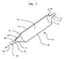
以下図面を参照する。図1は参照符号10にてカテーテルの末端部の周囲に設けられ、収縮した状態にあるバルーンを示す斜視図である。カテーテルは内側シャフト22、外側シャフト24、及びこれらの間を延びる膨張ルーメン(図示しない)を有する。流体がバルーンを拡張すべく膨張ルーメンを通じて供給されてもよい。負の圧力に作用されたときにバルーンは収縮してもよい。図示のバルーンは収縮した状態にあり、まだカテーテルアセンブリの周囲にて折り畳まれるか、或いは巻き付けられてはいない。本実施例において、バルーン10は胴体部12、円錐部14、及び本体部16を有する。図示のバルーン10は収縮した状態にあり、3つの翼部18を有する。これらの翼部は円錐部14及び胴体部12内に延び、これにより胴体部12は翼部の跡を有する。翼部がこれらの部分内に延びる量は本発明によるモールド成型方法を使用して様々な角度に制御可能である。
Reference is now made to the drawings. FIG. 1 is a perspective view showing a balloon in a deflated state, which is provided around the distal end portion of the catheter at
図1に示す構造体は説明を目的としたのみであり、本発明の範囲を限定するものではない。上述したようにバルーン10は2,3,4,5,6、或いはそれ以上の数の翼部を有し、三角形、矩形、正方形等のその他の形状の構造体を有してもよい。翼部18は三角形以外の形状を有してもよい。例えば、米国特許出願公開第2006/0015134号明細書を参照のこと。ここでその全体が開示されたものとする。
The structure shown in FIG. 1 is for illustrative purposes only and is not intended to limit the scope of the present invention. As described above, the
バルーン10は内側カテーテルシャフト22にその末端部28にて固定され、外側カテーテルシャフト24にその基端部26にて固定される。内側カテーテルシャフト22はガイドワイヤを収容するためのガイドワイヤルーメン30を画定する。ガイドワイヤは血管形成術やステント搬送等の医療の処置において患者の管腔内にてバルーン10を案内し操作するために使用される。
図示のバルーン10は更に長軸32を有する。バルーンが折り畳まれた場合に、翼部18は長軸32の周囲に巻き付けられる。周知のバルーン折り畳み装置及び技術が本発明によるバルーンの折り畳みや巻き付けに使用可能である。周知の技術は通常、部分的に拡張したバルーンの径方向内方に中心に向かって移動される多数の堅固なダイ状構造体を使用する。折り畳み処置において真空等の負の圧力がバルーンに作用される。バルーンは通常保持固定具に配置され、ダイがそのストロークの終端に至るまで部分的に拡張した状態に保持される。
The illustrated
真空がバルーンを収縮させるべく作用され、ダイの形状に対応する翼部を形成する。続いて翼部はバルーンの周囲にて巻き付けられ、巻かれる。3つの翼部の装置において、折り畳み装置のダイはバルーンの周囲にて周方向に120°の間隔にて離間して設けられる。バルーン折り畳み装置の例は米国特許出願公開第2003/083687号明細書、第2003/0163157号明細書に開示され、これらはその全体がここで開示されたものとする。その他の例は米国特許第5350361号明細書、第6126652号明細書、第6033380号明細書、米国特許出願公開第2002/163104号明細書を含み、これらはその全体がここで開示されてものとする。 A vacuum is applied to deflate the balloon, forming a wing corresponding to the shape of the die. Subsequently, the wing is wound around the balloon and wound. In the three-wing device, the dies of the folding device are provided at intervals of 120 ° in the circumferential direction around the balloon. Examples of balloon folding devices are disclosed in U.S. Patent Application Publication Nos. 2003/083687 and 2003/0163157, which are hereby incorporated in their entirety. Other examples include U.S. Pat. Nos. 5,350,361, 6,126,652, 6033380, U.S. Patent Application Publication No. 2002/163104, which are disclosed herein in their entirety. To do.
バルーンを容易に折り畳むために、本発明によるバルーンは折り畳まれた場合に第2の型枠に配置される。ここで開示される方法により形成されるバルーンは第1のバルーン形成工程により得られた形状を保持し、第2のバルーン形成工程により得られた形状を保持する。図2に本発明による第2の形成工程において使用可能な型枠100の一実施例が隠れ線による内側部分とともに斜視図として示される。バルーン構造体を画定するものは型枠凹部120の内側表面である。図示のバルーン型枠の凹部120はバルーン本体に対応する領域116、バルーン胴体領域に対応する領域112、バルーン円錐領域に対応する領域114を有する。図示の型枠の凹部は3つの翼部領域118を有する。凹部120の領域112の要部は全ての形成工程が完了した後にバルーンから取り払われる。
In order to easily fold the balloon, the balloon according to the invention is placed in the second formwork when folded. The balloon formed by the method disclosed herein retains the shape obtained by the first balloon formation step, and retains the shape obtained by the second balloon formation step. FIG. 2 shows a perspective view of one embodiment of a
図3は図2の3−3線における径方向断面図である。型枠凹部120の周囲124がバルーンの形状を画定する。本実施例においては、3つの翼部118を有する構造体が型枠凹部120の周囲124により画定される。
FIG. 3 is a radial cross-sectional view taken along line 3-3 in FIG. A
この型枠の周囲は第1のモールド成型工程において使用される型枠の周囲より大きい。好適には周囲は第1のモールド成形工程において使用される型枠の周囲より約5%乃至約30%大きい。 The perimeter of this mold is larger than the perimeter of the mold used in the first molding process. Preferably the perimeter is about 5% to about 30% greater than the perimeter of the mold used in the first molding step.
型枠10は形成したバルーンを容易に取り除くべく開放するように、或いは分解するように構成される。図4は図2,3に示すものと類似のバルーン型枠の別例をバルーン10と組み合わせて示す分解斜視図である。図示のバルーン10は部分的に型枠100の凹部120から取り払われ、胴体12、円錐14、及び本体16を有し、更に3つの翼部領域18を有する。この構造体は型枠100の凹部120に対応する。型枠の内側凹部の本体領域116は5つの翼部領域118を備えてもよい。型枠の外側表面は通常型枠の内側凹部の外径に対応する。しかしながら型枠の外側表面は得られるバルーンの形状に関係しない。
The
型枠は、アルミニウム、チタニウム、ステンレス鋼、被覆銅等の好適な型枠材料から構成されるが、これらに限定されるものではない。ガラスやセラミックも使用可能である。型枠は好適に熱伝導性材料から形成される。好ましくは型枠を形成する材料は高度に研磨されたガラス状の内側表面を更に備える。複合材料及び積層材料もここで使用可能である。 The formwork is composed of a suitable formwork material such as aluminum, titanium, stainless steel, or coated copper, but is not limited thereto. Glass and ceramic can also be used. The formwork is preferably formed from a thermally conductive material. Preferably, the material forming the mold further comprises a highly polished glassy inner surface. Composite materials and laminate materials can also be used here.
図5は別例における、5つの翼部を備えたバルーン構造体に対応する内側凹部を有する型枠100を示す。型枠100の内側表面は破線にて示す。型枠100は胴体領域112を画定する内側凹部120、円錐領域114、本体領域116、及び翼部領域118を画定する内側凹部120を有する。本実施例において、翼部118は円錐領域114内にも延びる。
FIG. 5 shows another
図6は図5の6−6線における径方向断面図である。図6は内側凹部120の構造をより詳細に示す。本実施例において内側凹部120の周囲124は五光星形状を画定する。このように得られるバルーンは五光星の、即ち5つの翼部からなる形状を有する。
6 is a radial cross-sectional view taken along line 6-6 of FIG. FIG. 6 shows the structure of the
図7は型枠100から開放された5つの翼部からなるバル―ン10と組み合わせて型枠100を示す部分分解斜視図である。繰り返すが本実施例において、型枠は形成されたバルーンを容易に取り除くべく開放するように、且つ分解するように構成される。バルーン10は円錐部114、胴体部112、及び本体部を有する。バルーン10は5つの翼部118を有する。型枠の内側凹部の本体領域116は5つの翼部領域118も備える。
FIG. 7 is a partially exploded perspective view showing the
本発明による型枠は温度を計測すべく熱電対等の好適なセンサを更に備えてもよい。これらのセンサは自動熱制御システムにフィードバックする。
別例においてシステムは加熱流体槽を使用してもよい。加熱流体槽を主要な加熱手段とするシステムにおいて、流体の撹拌、及び例えば超音波の振動による槽装置の振動のうち少なくともいずれか一方により槽からの熱転写が更に容易になる。
The formwork according to the present invention may further comprise a suitable sensor such as a thermocouple for measuring temperature. These sensors feed back to the automatic thermal control system.
In another example, the system may use a heated fluid bath. In a system in which a heated fluid tank is a main heating means, thermal transfer from the tank is further facilitated by at least one of fluid agitation and vibration of the tank device by, for example, ultrasonic vibration.
本発明によるバルーンは上述したようにモールド成形可能な好適なバルーン材料から形成される。好適な材料の種類は、ポリオレフィン、ポリアミド(例、ナイロン)、ポリエステル及び共重合ポリエステル、ポリエーテル、ポリイミド、ポリカーボネイト等を含むがこれらに限定されるものではない。共重合体も使用に好適である。 The balloon according to the invention is formed from a suitable balloon material that can be molded as described above. Suitable material types include, but are not limited to, polyolefins, polyamides (eg, nylon), polyesters and copolyesters, polyethers, polyimides, polycarbonates, and the like. Copolymers are also suitable for use.
好適なポリエステルの例として、ポリエチレンテレフタレート(PET)、ポリブチレンテレフタレート(PBT)、ポリエチレンナフタレート(PEN)等が挙げられるが、これらに限定されるものではない。 Examples of suitable polyesters include, but are not limited to, polyethylene terephthalate (PET), polybutylene terephthalate (PBT), polyethylene naphthalate (PEN), and the like.
独国Wilmingtonに所在するDuPont社から販売され、登録商標名がHYTRELであるポリエステル−エステルエラストマー、及びインディアナ州Evansvilleに所在するDSM Engineering Plastics−Americas社から販売され、登録商標名がARNITELであるポリエステルエステル及びポリエーテルエステルがここで使用可能である。これらの高分子材は所望のバルーンの特性に応じて異なるグレードが市場にて入手可能である。 A polyester-ester elastomer sold by DuPont, located in Wilmington, Germany, under the registered trade name HYTREL, and a polyester ester sold by DSM Engineering Plastics-Americas, located in Evansville, Indiana, under the registered trade name ARNITEL And polyetheresters can be used here. Different grades of these polymeric materials are available on the market depending on the desired balloon characteristics.
仏国パリに所在するArkema社から登録商標名PEBAXにて販売されているポリエーテルブロックアミドブロック共重合体等のブロック共重合体がここで使用可能である。登録商標PEBAXは異なるグレードが市場にて販売されており、例えばグレード6333、7033、及び7233は全て所望のバルーン特性に応じて好適である。 Block copolymers such as polyether block amide block copolymers sold under the trade name PEBAX from Arkema in Paris, France can be used here. The registered trademark PEBAX is sold in different grades in the market, for example grades 6333, 7033 and 7233 are all suitable depending on the desired balloon properties.
好適なポリアミドはナイロン6、ナイロン10、ナイロン11、及びナイロン12を含むが、これらに限定されるものではない。
ポリウレタンはミシガン州Midlandに所在するDow Chemical Co.から登録商標名ISOPLAST及び登録商標名PELLETHANEにて市場にて販売されている。
Suitable polyamides include, but are not limited to
Polyurethane is available from Dow Chemical Co., located in Midland, Michigan. Marketed under the registered trade name ISOPLAST and the registered trade name PELLETHANE.
これらの好適なバルーン材料、及び好適なバルーン材料の別例は米国特許第4906244号明細書、第5556383号明細書、及び第6270522号明細書に開示され、これらの全体がここで開示されたものとする。本発明はここで使用される高分子材に限定されるものではない。 These preferred balloon materials, and other examples of suitable balloon materials, are disclosed in US Pat. Nos. 4,906,244, 5,556,383, and 6,270,522, all of which are hereby disclosed. And The present invention is not limited to the polymer material used here.
液晶ポリマー等の補強材料もここで使用可能である。バルーンに使用される液晶ポリマーは米国特許第6242063号明細書、第6284333号明細書、及び第6596219号明細書に開示され、これらの全体がここで開示されたものとする。 Reinforcing materials such as liquid crystal polymers can also be used here. Liquid crystal polymers used in balloons are disclosed in U.S. Pat. Nos. 6,242,063, 6,284,333, and 6,596,219, all of which are disclosed herein.
上述したものは説明を目的としたものであり、本発明の範囲を限定するものではない。バルーン材料の選択は当業者に周知である。
実施例において、PEBAX(登録商標)7233の管状パリソンやバルーンプリフォームは押し出され、第1の型枠に配置される。型枠の本体領域は4.0mmの径及び中央の本体部にて計測されるπd、即ち4πの周囲を有する略球状の、或いは円形のバルーンの本体領域に対応する。図8乃至11に第1のモールド成型工程において使用可能な型枠100を示す。
What has been described above is for purposes of illustration and is not intended to limit the scope of the present invention. The selection of balloon material is well known to those skilled in the art.
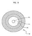
In an embodiment, a PEBAX® 7233 tubular parison or balloon preform is extruded and placed in a first formwork. The main body region of the mold corresponds to the main body region of a substantially spherical or circular balloon having a diameter of 4.0 mm and πd measured at the central main body, that is, around 4π. 8 to 11 show a
図8は内側部分を隠れ線にて示した斜視図である。型枠100は内側凹部220を有する。内側凹部220はバルーン本体部に対応する領域216、バルーン円錐部に対応する領域214、及びバルーン胴体部に対応する領域212を有する。後者の領域212の要部はバルーン形成工程が完了した場合に取り払われる。内側凹部220の領域216は略円形状を画定する。図9は図8の9−9線における径方向断面図である。
FIG. 8 is a perspective view showing the inner part with hidden lines. The
図10は図8,9に示す型枠と類似し、分解された部分と予め形成されたバルーン200とを備える本発明によるバルーン型枠100を示す斜視図である。バルーン200は本体領域316において略円形状を有する。図11は本発明によるバルーン型枠100と、予め形成されたバルーン200とを示す側面拡大図である。
FIG. 10 is a perspective view showing a
この型枠の例は説明を目的としたものであり、本発明の範囲を限定するものではない。本工程において使用される好適な型枠の別例は米国特許出願公開第2006/0033241号明細書に開示され、その全体がここで開示されたものとする。本工程において、温度T1は後述するモールド成型工程において使用される温度より好適に高い。本実施例において、予め形成されたバルーンを形成すべくバルーンは約95℃の温度T1にて径方向に拡張される。 This example of formwork is for illustrative purposes and is not intended to limit the scope of the present invention. Another example of a suitable formwork used in this process is disclosed in U.S. Patent Application Publication No. 2006/0033241, which is hereby incorporated in its entirety. In the present process, temperatures T 1 is preferably higher than the temperatures used in the molding step described later. In this example, the balloon is radially expanded at a temperature T 1 of about 95 ° C. to form a pre-formed balloon.
本工程における型枠温度はバルーンを形成するために選択される材料のタイプにより変化するが、好適に約90℃乃至約100℃の範囲にある。
本実施例における第1のモールド成型工程にて使用される圧力は約400psi(約2.8MPa)であり、張力は40グラムである。圧力は約300psi乃至約500psi(約2.0MPa乃至約3.5MPa)の範囲にあり、より好適には約350psi乃至約450psi(約2.4MPa乃至約3.1MPa)の範囲にある。
The mold temperature in this step varies with the type of material selected to form the balloon, but is preferably in the range of about 90 ° C to about 100 ° C.
The pressure used in the first molding step in this example is about 400 psi (about 2.8 MPa) and the tension is 40 grams. The pressure is in the range of about 300 psi to about 500 psi (about 2.0 MPa to about 3.5 MPa), more preferably in the range of about 350 psi to about 450 psi (about 2.4 MPa to about 3.1 MPa).
予め形成されたバルーンは続いて第1の型枠から取り外され、図2乃至7に開示されるタイプの第2の型枠内に配置される。この第2の型枠は4.5mmの僅かに大きな寸法を有する。図2乃至7に示す実施例において、径は周囲の値を使用して略概算される。即ち3つの翼部又は5つの翼部からなる星状構造体の全ての弧の長さの和をπにて割ったものである。しかしながらこの径の計算は全ての構造体に対して適切であるわけではない。第2の型枠の径方向断面の周囲は第1の型枠の径方向断面の周囲より約5%乃至約30%大きい。本実施例において、第2のモールド成型工程後の製造されたバルーンの周囲は第1のモールド成型工程後の製造されたバルーンの周囲(外周)より約12.5%大きい。 The preformed balloon is then removed from the first form and placed in a second form of the type disclosed in FIGS. This second form has a slightly larger dimension of 4.5 mm. In the embodiment shown in FIGS. 2-7, the diameter is approximately estimated using ambient values. That is, the sum of the lengths of all the arcs of the star structure consisting of three or five wings divided by π. However, this diameter calculation is not appropriate for all structures. The circumference of the radial cross section of the second mold is about 5% to about 30% larger than the circumference of the radial cross section of the first mold. In this example, the circumference of the manufactured balloon after the second molding process is about 12.5% larger than the circumference (outer periphery) of the manufactured balloon after the first molding process.
予め形成されたバルーンはこの第2の型枠内にて約75℃の温度にて径方向に拡張された。上述したように第2のモールド成型工程の温度T2はT1の温度より好適に約10%乃至約30%低い。本実施例において、T2は約90乃至75又は90、或いはT1より約17%小さい。第2のモールド成型工程の温度T2は、第1のモールド成型工程の温度T1より約10%乃至50%低く、好適に約10%乃至約30%低い場合に、約40℃乃至約90℃の範囲にあり、好適には約70℃乃至約90℃の範囲にある。 A pre-formed balloon was radially expanded in this second form at a temperature of about 75 ° C. Temperature T 2 of the second molding step as described above preferably from about 10% to about 30% lower than the temperature of T 1. In this example, T 2 is about 90 to 75 or 90, or about 17% less than T 1 . The temperature T 2 of the second molding process is about 40 ° C. to about 90 ° C. when the temperature T 1 of the first molding process is about 10% to 50% lower, preferably about 10% to about 30% lower. In the range of about 70 ° C to about 90 ° C.
第2のモールド成型工程にて使用される圧力は約500psi(約3.5MPa)であり、張力は250グラムであった。本実施例において、第2のモールド成型工程において使用される圧力P2は第1のモールド成型工程において使用される圧力P1より約25%大きい。 The pressure used in the second molding process was about 500 psi (about 3.5 MPa) and the tension was 250 grams. In this embodiment, the pressure P 2 which is used in the second molding step is about 25% greater than the pressure P 1 used in the first molding step.
バルーンは続いて温度T3にて殺菌される。温度T3は好適にT2より低い。通常の殺菌は約50℃乃至約60℃の間の温度にて実施可能である。通常使用される方法においてはバルーン殺菌用のエチレンオキサイドガス(EtO)を使用する。これらの殺菌技術は本技術分野において周知である。 The balloon is sterilized by followed by temperature T 3. Temperature T 3 is lower than the suitably T 2. Normal sterilization can be performed at temperatures between about 50 ° C and about 60 ° C. In a method usually used, ethylene oxide gas (EtO) for balloon sterilization is used. These sterilization techniques are well known in the art.
前記例及び開示事項は、例示的なものであり、包括的なものではない。これらの例及び記載は、当業者に対して、様々な変更例や別例を提案するものである。これらすべての別例及び変更例については、特許請求の範囲に含まれるものであり、特許請求の範囲における「〜からなる、〜から構成される」という語は「〜を含む」という意味であり、「〜に限定される」という意味ではない。当業者であれば、本明細書に記載された特定の実施形態と均等である他の技術も、本願の請求項に包含されるものであることが理解されるであろう。 The foregoing examples and disclosure are intended to be illustrative and not exhaustive. These examples and descriptions suggest various modifications and alternatives to those skilled in the art. All these alternatives and modifications are included in the scope of claims, and the word “consisting of” in the claims means “including”. , Does not mean “limited to”. Those skilled in the art will appreciate that other techniques equivalent to the specific embodiments described herein are also intended to be encompassed by the claims herein.
本国際出願は、2006年8月28日に出願された米国特許出願第11/511156号に基づいて優先権を主張するものであり、同米国出願は本明細書に開示されたものとする。 This international application claims priority based on US patent application Ser. No. 11 / 511,156 filed Aug. 28, 2006, which is hereby incorporated by reference.
Claims (22)
同バルーンプリフォームを第1の型枠に配置する工程であって、第1の型枠は内側の凹部を有し、同第1の型枠の内側の凹部の径方向断面は第1の径により画定される第1の配置工程と、
予め形成されたバルーンを形成すべく同第1の型枠のバルーンプリフォームを温度T1、且つ圧力P1にて径方向に拡張する工程と、
同予め形成されたバルーンを第2の型枠内に配置する工程であって、第2の型枠は内側の凹部を有し、同第2の型枠の内側の凹部の径方向断面は第1の型枠の第1の周囲より大きい第2の周囲によって画定される第2の配置工程と、
該第2の型枠内の予め形成されたバルーンを温度T2、且つ圧力P2にて径方向に拡張する工程であって、T2はT1より小さい拡張工程とを含むことを特徴とする医療器具用の拡張可能なバルーンの製造方法。 Providing a balloon preform;
The step of disposing the balloon preform in a first mold, wherein the first mold has an inner recess, and the radial cross section of the inner recess of the first mold is a first diameter. A first placement step defined by:
Expanding the balloon preform of the first mold in a radial direction at a temperature T 1 and a pressure P 1 to form a pre-formed balloon;
The step of disposing the pre-formed balloon in the second mold, wherein the second mold has an inner recess, and the radial cross section of the inner recess of the second mold is A second placement step defined by a second perimeter that is greater than the first perimeter of the one formwork;
A step of radially expanding a preformed balloon in the second mold form at a temperature T 2 and a pressure P 2 , wherein T 2 includes an expansion step smaller than T 1. A method for manufacturing an expandable balloon for a medical device.
第1の周を有する径方向断面を備える予め形成されたバルーンを提供する工程と、
同予め形成されたバルーンを膨張媒体により膨張させる工程と、
同膨張媒体を解放し、同時に予め形成されたバルーンに熱処理刃を作用させる工程とを含むことを特徴とする収縮後のバルーンの再折り畳み性を向上させる方法。 A method for improving the refoldability of a balloon after deflation,
Providing a preformed balloon with a radial cross section having a first circumference;
Inflating the pre-formed balloon with an inflation medium;
Releasing the same inflation medium and simultaneously applying a heat treatment blade to a pre-formed balloon, and improving the refoldability of the balloon after deflation.
Applications Claiming Priority (2)
| Application Number | Priority Date | Filing Date | Title |
|---|---|---|---|
| US11/511,156 US8609016B2 (en) | 2006-08-28 | 2006-08-28 | Refoldable balloon and method of making and using the same |
| PCT/US2007/011010 WO2008027088A2 (en) | 2006-08-28 | 2007-05-07 | Refoldable balloon and method of making and using the same |
Publications (2)
| Publication Number | Publication Date |
|---|---|
| JP2010502269A true JP2010502269A (en) | 2010-01-28 |
| JP2010502269A5 JP2010502269A5 (en) | 2010-11-25 |
Family
ID=38566744
Family Applications (1)
| Application Number | Title | Priority Date | Filing Date |
|---|---|---|---|
| JP2009526592A Pending JP2010502269A (en) | 2006-08-28 | 2007-05-07 | Refoldable balloon and method for making and using the same |
Country Status (5)
| Country | Link |
|---|---|
| US (1) | US8609016B2 (en) |
| EP (1) | EP2056915B1 (en) |
| JP (1) | JP2010502269A (en) |
| CA (1) | CA2657871A1 (en) |
| WO (1) | WO2008027088A2 (en) |
Families Citing this family (49)
| Publication number | Priority date | Publication date | Assignee | Title |
|---|---|---|---|---|
| US20070244501A1 (en) * | 2006-04-18 | 2007-10-18 | Horn Daniel J | Medical balloons |
| US9867530B2 (en) | 2006-08-14 | 2018-01-16 | Volcano Corporation | Telescopic side port catheter device with imaging system and method for accessing side branch occlusions |
| JP5524835B2 (en) | 2007-07-12 | 2014-06-18 | ヴォルカノ コーポレイション | In vivo imaging catheter |
| US9596993B2 (en) | 2007-07-12 | 2017-03-21 | Volcano Corporation | Automatic calibration systems and methods of use |
| WO2009009802A1 (en) | 2007-07-12 | 2009-01-15 | Volcano Corporation | Oct-ivus catheter for concurrent luminal imaging |
| US11141063B2 (en) | 2010-12-23 | 2021-10-12 | Philips Image Guided Therapy Corporation | Integrated system architectures and methods of use |
| US11040140B2 (en) | 2010-12-31 | 2021-06-22 | Philips Image Guided Therapy Corporation | Deep vein thrombosis therapeutic methods |
| WO2013033592A1 (en) | 2011-08-31 | 2013-03-07 | Volcano Corporation | Optical-electrical rotary joint and methods of use |
| US11272845B2 (en) | 2012-10-05 | 2022-03-15 | Philips Image Guided Therapy Corporation | System and method for instant and automatic border detection |
| JP2015532536A (en) | 2012-10-05 | 2015-11-09 | デイビッド ウェルフォード, | System and method for amplifying light |
| US9367965B2 (en) | 2012-10-05 | 2016-06-14 | Volcano Corporation | Systems and methods for generating images of tissue |
| US10070827B2 (en) | 2012-10-05 | 2018-09-11 | Volcano Corporation | Automatic image playback |
| US9307926B2 (en) | 2012-10-05 | 2016-04-12 | Volcano Corporation | Automatic stent detection |
| US9286673B2 (en) | 2012-10-05 | 2016-03-15 | Volcano Corporation | Systems for correcting distortions in a medical image and methods of use thereof |
| US10568586B2 (en) | 2012-10-05 | 2020-02-25 | Volcano Corporation | Systems for indicating parameters in an imaging data set and methods of use |
| US9292918B2 (en) | 2012-10-05 | 2016-03-22 | Volcano Corporation | Methods and systems for transforming luminal images |
| US9858668B2 (en) | 2012-10-05 | 2018-01-02 | Volcano Corporation | Guidewire artifact removal in images |
| US9324141B2 (en) | 2012-10-05 | 2016-04-26 | Volcano Corporation | Removal of A-scan streaking artifact |
| US9840734B2 (en) | 2012-10-22 | 2017-12-12 | Raindance Technologies, Inc. | Methods for analyzing DNA |
| WO2014093374A1 (en) | 2012-12-13 | 2014-06-19 | Volcano Corporation | Devices, systems, and methods for targeted cannulation |
| EP2934310A4 (en) | 2012-12-20 | 2016-10-12 | Nathaniel J Kemp | Optical coherence tomography system that is reconfigurable between different imaging modes |
| CA2895502A1 (en) | 2012-12-20 | 2014-06-26 | Jeremy Stigall | Smooth transition catheters |
| JP2016506276A (en) | 2012-12-20 | 2016-03-03 | ジェレミー スティガール, | Locate the intravascular image |
| US11406498B2 (en) | 2012-12-20 | 2022-08-09 | Philips Image Guided Therapy Corporation | Implant delivery system and implants |
| US10939826B2 (en) | 2012-12-20 | 2021-03-09 | Philips Image Guided Therapy Corporation | Aspirating and removing biological material |
| US10942022B2 (en) | 2012-12-20 | 2021-03-09 | Philips Image Guided Therapy Corporation | Manual calibration of imaging system |
| US10993694B2 (en) | 2012-12-21 | 2021-05-04 | Philips Image Guided Therapy Corporation | Rotational ultrasound imaging catheter with extended catheter body telescope |
| WO2014099760A1 (en) | 2012-12-21 | 2014-06-26 | Mai Jerome | Ultrasound imaging with variable line density |
| US10191220B2 (en) | 2012-12-21 | 2019-01-29 | Volcano Corporation | Power-efficient optical circuit |
| US9383263B2 (en) | 2012-12-21 | 2016-07-05 | Volcano Corporation | Systems and methods for narrowing a wavelength emission of light |
| US9612105B2 (en) | 2012-12-21 | 2017-04-04 | Volcano Corporation | Polarization sensitive optical coherence tomography system |
| US10058284B2 (en) | 2012-12-21 | 2018-08-28 | Volcano Corporation | Simultaneous imaging, monitoring, and therapy |
| CA2895940A1 (en) | 2012-12-21 | 2014-06-26 | Andrew Hancock | System and method for multipath processing of image signals |
| EP2936426B1 (en) | 2012-12-21 | 2021-10-13 | Jason Spencer | System and method for graphical processing of medical data |
| US9486143B2 (en) | 2012-12-21 | 2016-11-08 | Volcano Corporation | Intravascular forward imaging device |
| US10413317B2 (en) | 2012-12-21 | 2019-09-17 | Volcano Corporation | System and method for catheter steering and operation |
| US10226597B2 (en) | 2013-03-07 | 2019-03-12 | Volcano Corporation | Guidewire with centering mechanism |
| WO2014138555A1 (en) | 2013-03-07 | 2014-09-12 | Bernhard Sturm | Multimodal segmentation in intravascular images |
| US10638939B2 (en) | 2013-03-12 | 2020-05-05 | Philips Image Guided Therapy Corporation | Systems and methods for diagnosing coronary microvascular disease |
| US11154313B2 (en) | 2013-03-12 | 2021-10-26 | The Volcano Corporation | Vibrating guidewire torquer and methods of use |
| US11026591B2 (en) | 2013-03-13 | 2021-06-08 | Philips Image Guided Therapy Corporation | Intravascular pressure sensor calibration |
| US9301687B2 (en) | 2013-03-13 | 2016-04-05 | Volcano Corporation | System and method for OCT depth calibration |
| EP2967488B1 (en) | 2013-03-13 | 2021-06-16 | Jinhyoung Park | System for producing an image from a rotational intravascular ultrasound device |
| US10292677B2 (en) | 2013-03-14 | 2019-05-21 | Volcano Corporation | Endoluminal filter having enhanced echogenic properties |
| US10219887B2 (en) | 2013-03-14 | 2019-03-05 | Volcano Corporation | Filters with echogenic characteristics |
| WO2014152365A2 (en) | 2013-03-14 | 2014-09-25 | Volcano Corporation | Filters with echogenic characteristics |
| CN104721943A (en) * | 2013-12-24 | 2015-06-24 | 微创心脉医疗科技(上海)有限公司 | Balloon, balloon expander catheter and manufacturing method and former of balloon |
| US20150297807A1 (en) | 2014-01-30 | 2015-10-22 | Volcano Corporation | Devices and methods for treating fistulas |
| WO2015195752A1 (en) | 2014-06-17 | 2015-12-23 | Covidien Lp | Medical balloon including pleats |
Citations (3)
| Publication number | Priority date | Publication date | Assignee | Title |
|---|---|---|---|---|
| JP2003062080A (en) * | 2001-08-29 | 2003-03-04 | Terumo Corp | Shape memory balloon, manufacturing method and balloon catheter therefor |
| JP2004298356A (en) * | 2003-03-31 | 2004-10-28 | Nippon Zeon Co Ltd | Balloon for dilation and balloon catheter with the same |
| JP2006502801A (en) * | 2002-10-15 | 2006-01-26 | ボストン サイエンティフィック リミテッド | Expansion control type balloon |
Family Cites Families (34)
| Publication number | Priority date | Publication date | Assignee | Title |
|---|---|---|---|---|
| US4490421A (en) * | 1983-07-05 | 1984-12-25 | E. I. Du Pont De Nemours And Company | Balloon and manufacture thereof |
| US4935190A (en) * | 1987-07-10 | 1990-06-19 | William G. Whitney | Method of making balloon retention catheter |
| US4950239A (en) * | 1988-08-09 | 1990-08-21 | Worldwide Medical Plastics Inc. | Angioplasty balloons and balloon catheters |
| US4906244A (en) * | 1988-10-04 | 1990-03-06 | Cordis Corporation | Balloons for medical devices and fabrication thereof |
| US5318587A (en) * | 1989-08-25 | 1994-06-07 | C. R. Bard, Inc. | Pleated balloon dilatation catheter and method of use |
| EP0974370B1 (en) * | 1990-11-09 | 2006-04-19 | Boston Scientific Corporation | Balloon for medical catheter |
| US5264260A (en) * | 1991-06-20 | 1993-11-23 | Saab Mark A | Dilatation balloon fabricated from low molecular weight polymers |
| JPH05192408A (en) * | 1991-09-06 | 1993-08-03 | C R Bard Inc | Production of expansion balloon |
| JP3053029B2 (en) * | 1991-10-08 | 2000-06-19 | テルモ株式会社 | Vascular dilatation catheter balloon |
| US5226887A (en) * | 1992-02-07 | 1993-07-13 | Interventional Technologies, Inc. | Collapsible folding angioplasty balloon |
| EP0569263B1 (en) * | 1992-04-06 | 1997-07-02 | Terumo Kabushiki Kaisha | Balloon catheter |
| US5500180A (en) * | 1992-09-30 | 1996-03-19 | C. R. Bard, Inc. | Method of making a distensible dilatation balloon using a block copolymer |
| US5350361A (en) * | 1993-11-10 | 1994-09-27 | Medtronic, Inc. | Tri-fold balloon for dilatation catheter and related method |
| CA2160487C (en) * | 1994-02-17 | 2003-09-23 | Lixiao Wang | Process improvements for preparing catheter balloons |
| DK0748232T4 (en) * | 1994-03-02 | 2009-01-19 | Boston Scient Scimed Inc | Catheter balloons of block copolymer elastomers |
| US6146356A (en) * | 1994-03-02 | 2000-11-14 | Scimed Life Systems, Inc. | Block copolymer elastomer catheter balloons |
| US5456666A (en) * | 1994-04-26 | 1995-10-10 | Boston Scientific Corp | Medical balloon folding into predetermined shapes and method |
| US5833657A (en) * | 1995-05-30 | 1998-11-10 | Ethicon, Inc. | Single-walled balloon catheter with non-linear compliance characteristic |
| US6284333B1 (en) * | 1997-09-10 | 2001-09-04 | Scimed Life Systems, Inc. | Medical devices made from polymer blends containing low melting temperature liquid crystal polymers |
| US6242063B1 (en) * | 1997-09-10 | 2001-06-05 | Scimed Life Systems, Inc. | Balloons made from liquid crystal polymer blends |
| US6033380A (en) * | 1998-02-13 | 2000-03-07 | Cordis Corporation | Six-pleated catheter balloon and device for forming same |
| US6126652A (en) * | 1998-09-08 | 2000-10-03 | Medtronic Inc. | Catheter balloon refolding tool and method of use |
| US6325780B1 (en) * | 1999-09-13 | 2001-12-04 | Advanced Cardiovascular Systems, Inc. | Inflatable member formed of liquid crystal polymeric material blend |
| US6733513B2 (en) * | 1999-11-04 | 2004-05-11 | Advanced Bioprosthetic Surfaces, Ltd. | Balloon catheter having metal balloon and method of making same |
| US6270522B1 (en) * | 1999-12-21 | 2001-08-07 | Advanced Cardiovascular Systems, Inc. | High pressure catheter balloon |
| US6572813B1 (en) * | 2000-01-13 | 2003-06-03 | Advanced Cardiovascular Systems, Inc. | Balloon forming process |
| ATE369890T1 (en) | 2001-03-26 | 2007-09-15 | Mach Solutions Inc | BALLOON FOLDING TECHNOLOGY |
| US6946092B1 (en) * | 2001-09-10 | 2005-09-20 | Scimed Life Systems, Inc. | Medical balloon |
| US7479149B2 (en) | 2001-10-25 | 2009-01-20 | Boston Scientific Scimed, Inc. | Balloon configuring apparatus |
| US7160317B2 (en) * | 2002-01-04 | 2007-01-09 | Boston Scientific Scimed, Inc. | Multiple-wing balloon catheter to reduce damage to coated expandable medical implants |
| US7951164B2 (en) * | 2002-02-28 | 2011-05-31 | Boston Scientific Scimed, Inc. | Balloon folding apparatus, methods and products |
| US7972351B2 (en) * | 2004-07-13 | 2011-07-05 | Boston Scientific Scimed, Inc. | Balloon folding design and method and apparatus for making balloons |
| US7435077B2 (en) * | 2004-08-13 | 2008-10-14 | Boston Scientific Scimed, Inc. | Catheter balloon molding device |
| US20070205539A1 (en) | 2006-03-03 | 2007-09-06 | Boston Scientific Scimed, Inc. | Balloon mold design |
-
2006
- 2006-08-28 US US11/511,156 patent/US8609016B2/en active Active
-
2007
- 2007-05-07 CA CA002657871A patent/CA2657871A1/en not_active Abandoned
- 2007-05-07 WO PCT/US2007/011010 patent/WO2008027088A2/en active Application Filing
- 2007-05-07 EP EP07794612.7A patent/EP2056915B1/en not_active Not-in-force
- 2007-05-07 JP JP2009526592A patent/JP2010502269A/en active Pending
Patent Citations (3)
| Publication number | Priority date | Publication date | Assignee | Title |
|---|---|---|---|---|
| JP2003062080A (en) * | 2001-08-29 | 2003-03-04 | Terumo Corp | Shape memory balloon, manufacturing method and balloon catheter therefor |
| JP2006502801A (en) * | 2002-10-15 | 2006-01-26 | ボストン サイエンティフィック リミテッド | Expansion control type balloon |
| JP2004298356A (en) * | 2003-03-31 | 2004-10-28 | Nippon Zeon Co Ltd | Balloon for dilation and balloon catheter with the same |
Also Published As
| Publication number | Publication date |
|---|---|
| US20080124495A1 (en) | 2008-05-29 |
| WO2008027088A3 (en) | 2008-04-17 |
| EP2056915A2 (en) | 2009-05-13 |
| CA2657871A1 (en) | 2008-03-06 |
| US8609016B2 (en) | 2013-12-17 |
| WO2008027088A2 (en) | 2008-03-06 |
| EP2056915B1 (en) | 2014-05-07 |
Similar Documents
| Publication | Publication Date | Title |
|---|---|---|
| JP2010502269A (en) | Refoldable balloon and method for making and using the same | |
| JP5047791B2 (en) | Balloon folding design and method and apparatus for manufacturing a balloon | |
| US9216033B2 (en) | System and method for treating biological vessels | |
| EP0868926B1 (en) | Coextruded balloon | |
| EP2636422B1 (en) | Cutting balloon with connector and dilation element | |
| US7226472B2 (en) | Catheter balloon with advantageous cone design | |
| US20070112300A1 (en) | Balloon folding design, apparatus and method of making the same | |
| JP6506734B2 (en) | Material reduction tip portion of catheter and method for forming the same | |
| US7147817B1 (en) | Method of making a low profile balloon | |
| JP4850707B2 (en) | Balloon assembly with torque | |
| US20090234282A1 (en) | Outer Catheter Shaft to Balloon Joint | |
| CA2523985A1 (en) | Balloon catheter and method of manufacturing the same | |
| JP2004298354A (en) | Dilation balloon, and balloon catheter equipped with the same | |
| EP3220995B1 (en) | Inflatable device with etched modifications and method of fabricating thereof | |
| JP2004298356A (en) | Balloon for dilation and balloon catheter with the same | |
| US20170354524A1 (en) | Multilayer balloons |
Legal Events
| Date | Code | Title | Description |
|---|---|---|---|
| A521 | Written amendment |
Free format text: JAPANESE INTERMEDIATE CODE: A523 Effective date: 20100426 |
|
| A621 | Written request for application examination |
Free format text: JAPANESE INTERMEDIATE CODE: A621 Effective date: 20100426 |
|
| A521 | Written amendment |
Free format text: JAPANESE INTERMEDIATE CODE: A523 Effective date: 20101008 |
|
| A977 | Report on retrieval |
Free format text: JAPANESE INTERMEDIATE CODE: A971007 Effective date: 20120203 |
|
| A131 | Notification of reasons for refusal |
Free format text: JAPANESE INTERMEDIATE CODE: A131 Effective date: 20120214 |
|
| RD04 | Notification of resignation of power of attorney |
Free format text: JAPANESE INTERMEDIATE CODE: A7424 Effective date: 20120302 |
|
| A601 | Written request for extension of time |
Free format text: JAPANESE INTERMEDIATE CODE: A601 Effective date: 20120514 |
|
| A602 | Written permission of extension of time |
Free format text: JAPANESE INTERMEDIATE CODE: A602 Effective date: 20120521 |
|
| A02 | Decision of refusal |
Free format text: JAPANESE INTERMEDIATE CODE: A02 Effective date: 20121016 |